This guide provides an overview and description of the line modules (LMs), switchroute processor (SRP) modules, switch fabric modules (SFMs), and input/outputadapters (IOAs) available for the E320 router.
NOTE: A release may support multiple versions of a module or IOA. For information,see Software Compatibility in JUNOSe System Basics Configuration Guide, Chapter6, Managing Modules.
Table 1 lists the modules and IOAs supported by the router.
This book also contains the following appendixes:
“IOA Protocol Support” on page 39
“Slot Combinations” on page 51
“Module Name Cross-Reference Information” on page 53
“Product Reclamation and Recycling Program” on page 55
For more information about E320 routers, modules, and IOAs, refer to the followingbooks:
Module installation and maintenance—E320 Hardware Guide
Managing E320 routers—JUNOSe System Basics Configuration Guide
Configuring E320 modules—JUNOSe Link Layer Configuration Guide
2
Table 1: E320 Modules and IOAs
Module/IOA Type Module LabelFirst JUNOSeSupport Page
Line Module
LM-4 ES24GLM
7.0.1 5
LM-10 Uplink ES210G
UPLINKLM
7.2.0 6
LM-10 ES210G LM
8.0.0 8
SRP Module
SRP-100 SRP-100 7.0.1 10
SRP-320 SRP-320 7.3.0 12
SFM Module
SFM-100 SFM-100 7.0.1 14
SFM-320 SFM-320 7.3.0 15
Gigabit Ethernet IOA
GE-4 IOA ES2-S1GE-4IOA
7.0.1 16
GE-8 IOA ES2-S1GE-8IOA
7.2.0 19
10GE IOA ES2-S110GEIOA
7.0.1 22
10GE PR IOA ES2-S210GE PR
IOA
7.2.0 25
OC3/STM1 ATM IOA
OC3/STM1-8 ATM IOA ES2-S1OC3-8STM1
ATM IOA
7.0.1 28
OC12/STM4 ATM IOA
OC12/STM4-2 ATM IOA ES2-S1OC12-2STM4
ATM IOA
7.0.1 30
OC12/STM4 POS IOA
3
Module/IOA Type Module LabelFirst JUNOSeSupport Page
OC12/STM4-2 POS IOA ES2-S1OC12-2STM4
POS IOA
7.0.1 32
OC48/STM16 IOA
OC48/STM16 POS IOA ES2-S1OC48STM16
POS IOA
7.0.1 34
Redundancy IOA
REDUND IOA ES2-S1REDUND
IOA
7.0.1 36
Service IOA
SERVICE IOA ES2-S1SERVICE
IOA
7.0.1 37
SRP IOA
SRP IOA SRP IOA 7.0.1 38
4
LM-4 Line Module
LM-4 Line Module
Module label ES2 4G LM
Number of ports Not applicable
Software release First supported: 7.0.1
Description 200 W
Acts as frame forwarding engines for the physicalinterfaces
Responsible for processing data traffic
Pairs with IOAs to process data from different typesof network connections
Capability Supports a line rate of 128–byte packets on IOAs
The 100–Gbps switch fabric allocates 3.4 Gbps ofoverall bandwidth to each regular line module slotand 10 Gbps of overall bandwidth to each of the turboslots (slot 2 and slot 4).
The 320–Gbps switch fabric allocates 10 Gbps ofoverall bandwidth to each line module slot.
See JUNOSe System Basics Configuration Guide,Chapter 6, Managing Modules for more information.
Software features Not applicable
Line module compatibility Not applicable
SRP module compatibility SRP-100
SRP-320
Line module redundancy compatibility Yes (Redundancy IOA must be installed in either slot0 or slot 11)
Port redundancy support Not applicable
Cables and connectors Not applicable
LEDs When lit, LED indicates:
OK (green)—Self-test passed
FAIL (red)—Failure detected
ONLINE (green)—Online with no alarms or errors
REDUN (green)—Redundant card available
Alarms, errors, and events See Monitoring Modules in JUNOSe System BasicsConfiguration Guide, Chapter 6, Managing Modules .
LM-4 Line Module 5
LM-10 Uplink Line Module
Module label ES2 10G UPLINK LM
Number of ports Not applicable
Software release First supported: 7.2.0
Description 150 W
Acts as frame forwarding engines for the physicalinterfaces
Processes up to 10 Gb of data traffic
Pairs with ES2–S2 10GE PR IOA only
In a SRP-100 configuration, it must be installed in aturbo slot only (slot 2 or slot 4)
If you install the line module in a slot otherthan slot 2 or slot 4, it will be disabledIf you install a LM-10 Uplink module next to aconfigured line module that is already installedin slot 3 or slot 5, the LM-10 Uplink modulewill be disabledIf you install a line module in slot 3 or slot5 next to a previously installed LM-10 Uplinkmodule, the non-LM-10 Uplink module will bedisabled
In a SRP-320 configuration, it can be installed inany slot
Capability Supports a line rate of 128–byte frames on IOAs
The 100–Gbps switch fabric allocates 3.4 Gbps ofoverall bandwidth to each regular line module slotand 10 Gbps of overall bandwidth to each of the turboslots (slot 2 and slot 4).
The 320–Gbps switch fabric allocates 10 Gbps ofoverall bandwidth to each line module slot.
See JUNOSe System Basics Configuration Guide,Chapter 6, Managing Modules for more information.
Software features Not applicable
Line module compatibility Not applicable
SRP module compatibility SRP-100
SRP-320
Line module redundancy compatibility Does not support line module redundancy
Port redundancy support Not applicable
Cables and connectors Not applicable
6 LM-10 Uplink Line Module
LM-10 Uplink Line Module
LEDs When lit, LED indicates:
OK (green)—Self-test passed
FAIL (red)—Failure detected
ONLINE (green)—Online with no alarms or errors
REDUN (green)—Redundant card available
Alarms, errors, and events See Monitoring Modules in JUNOSe System BasicsConfiguration Guide, Chapter 6, Managing Modules .
LM-10 Uplink Line Module 7
LM-10 Line Module
Module label ES2 10G LM
Number of ports Not applicable
Software release First supported: 8.0.0
Description 215 W
Acts as frame forwarding engines for the physicalinterfaces
Processes up to 10 Gb of data traffic
Pairs with ES2–S2 10GE PR IOA and ES2–S1 GE-8 IOA
In a SRP-100 configuration, it must be installed in aturbo slot only (slot 2 or slot 4)
If you install the line module in a slot otherthan slot 2 or slot 4, it will be disabledIf you install the LM-10 module next to aconfigured line module that is already installedin slot 3 or slot 5, the LM-10 module will bedisabledIf you install a line module in slot 3 or slot 5next to a previously installed LM-10 module,the non-LM-10 module will be disabled
In a SRP-320 configuration, it can be installed inany slot
Capability Supports a line rate of 128–byte frames on IOAs
The 100–Gbps switch fabric allocates 3.4 Gbps ofoverall bandwidth to each regular line module slotand 10 Gbps of overall bandwidth to each of the turboslots (slot 2 and slot 4).
The 320–Gbps switch fabric allocates 10 Gbps ofoverall bandwidth to each line module slot.
See JUNOSe System Basics Configuration Guide,Chapter 6, Managing Modules for more information.
Software features Not applicable
Line module compatibility Not applicable
SRP module compatibility SRP-100
SRP-320
Line module redundancy compatibility Does not support line module redundancy
Port redundancy support Not applicable
Cables and connectors Not applicable
8 LM-10 Line Module
LM-10 Line Module
LEDs When lit, LED indicates:
OK (green)—Self-test passed
FAIL (red)—Failure detected
ONLINE (green)—Online with no alarms or errors
REDUN (green)—Redundant card available
Alarms, errors, and events See Monitoring Modules in JUNOSe System BasicsConfiguration Guide, Chapter 6, Managing Modules .
LM-10 Line Module 9
SRP-100 Module
Module label SRP-100
IOA label SRP IOA
Number of IOA ports Not applicable
Software release First supported: 7.0.1
Description 75 W
Switch route processor (100 Gbps)
Performs system management, route tablecalculations and maintenance, forwarding tablecomputations, statistics processing, configurationstorage, and other control plane functions
Has 2 GB of memory
Works with the SFM–100 module to create a switchfabric
Uses a PCMCIA nonvolatile storage (NVS) card tostore the system’s software and configuration files
Must be installed only with SRP-100 module andSFM–100 modules
Capability Not applicable
Software features Not applicable
Line module compatibility ES2 4G LM
ES2 10G UPLINK LM
SRP module compatibility Cannot use with SRP-320 module or SFM-320 module
Module redundancy support 1:1 redundancy
Port redundancy support Not applicable
Cables and connectors Not applicable
10 SRP-100 Module
SRP-100 Module
LEDs Board-level LEDs:
OK (green)—Self-test passed
FAIL (red)—Failure detected
ONLINE (green)—Online with no alarms or errors
REDUN (green)—Module is the spare systemcontroller, is up, and is ready to take the role of theonline system controller. When LED is not lit, moduleis not acting as the spare system controller.
PA (green)—Power source on source A
PB (green)—Power source on source B
FO (green)—Fan OK
FF (red)—Fan failure
LK (green)—Ethernet link up
AC (green)—Blinks when there is Ethernet activity(traffic) on link
Flash Card Port LEDs:
0 (green)—When lit, indicates slot is busy
1 (green)—When lit, indicates slot is busy
Alarms, errors, and events See Monitoring Modules in JUNOSe System BasicsConfiguration Guide, Chapter 6, Managing Modules .
SRP-100 Module 11
SRP-320 Module
Module label SRP-320
IOA label SRP IOA
Number of IOA ports Not applicable
Software release First supported: 7.3.0
Description 140 W
Switch route processor (320 Gbps)
Performs system management, route tablecalculations and maintenance, forwarding tablecomputations, statistics processing, configurationstorage, and other control plane functions
Has 4 GB of memory
Works with the SFM–320 module to create a switchfabric
The 320–Gbps fabric allocates 10 Gbps ofoverall bandwidth to each line module slot.
Uses an ATA flash card to store the system’s softwareand configuration files
Two flash cards are required for operation
Must be installed only with SRP-320 module andSFM–320 modules
Capability Not applicable
Software features Not applicable
Line module compatibility ES2 4G LM
ES2 10G UPLINK LM
SRP module compatibility Cannot use with SRP-100 module or SFM-100 module
Module redundancy support 1:1 redundancy
Port redundancy support Not applicable
Cables and connectors Not applicable
12 SRP-320 Module
SRP-320 Module
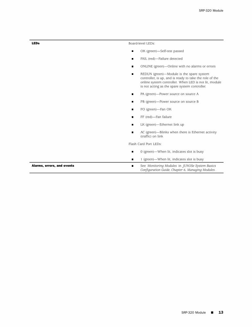
LEDs Board-level LEDs:
OK (green)—Self-test passed
FAIL (red)—Failure detected
ONLINE (green)—Online with no alarms or errors
REDUN (green)—Module is the spare systemcontroller, is up, and is ready to take the role of theonline system controller. When LED is not lit, moduleis not acting as the spare system controller.
PA (green)—Power source on source A
PB (green)—Power source on source B
FO (green)—Fan OK
FF (red)—Fan failure
LK (green)—Ethernet link up
AC (green)—Blinks when there is Ethernet activity(traffic) on link
Flash Card Port LEDs:
0 (green)—When lit, indicates slot is busy
1 (green)—When lit, indicates slot is busy
Alarms, errors, and events See Monitoring Modules in JUNOSe System BasicsConfiguration Guide, Chapter 6, Managing Modules .
SRP-320 Module 13
SFM-100 Module
Module label SFM-100
IOA label Not applicable
Number of IOA ports Not applicable
Software release First supported: 7.0.1
Description 40 W
Switch fabric module (100 Gbps)
Works with the SRP-100 module to create a switchfabric
Must be installed only with SRP-100 module andSFM–100 modules
Capability Not applicable
Software features Not applicable
Line module compatibility ES2 4G LM
ES2 10G UPLINK LM
SRP module compatibility SRP-100
Cannot use with SRP-320 module or SFM-320 module
Module redundancy support N+1 redundancy
Port redundancy support Not applicable
Cables and connectors Not applicable
LEDs When lit, LED indicates:
OK (green)—Self-test passed
FAIL (red)—Failure detected
ONLINE (green)—Online with no alarms or errors
REDUN (green)—N+1 redundancy is enabled; 2SRPs and 3 SFMs must be installed and working.When LED is unlit, one of the five fabric slices is downor not installed; N+1 redundancy is not enabled.
NOTE: When REDUN LED is on, the module may beremoved without interrupting service.
Alarms, errors, and events See Monitoring Modules in JUNOSe System BasicsConfiguration Guide, Chapter 6, Managing Modules .
14 SFM-100 Module
SFM-320 Module
SFM-320 Module
Module label SFM-320
IOA label Not applicable
Number of IOA ports Not applicable
Software release First supported: 7.3.0
Description 95 W
Switch fabric module (320 Gbps)
Works with the SRP-320 module to create a switchfabric
The 320–Gbps fabric allocates 10 Gbps ofoverall bandwidth to each line module slot.
Must be installed only with SRP-320 module andSFM–320 modules
Capability Not applicable
Software features Not applicable
Line module compatibility ES2 4G LM
ES2 10G UPLINK LM
SRP module compatibility SRP-320
Cannot use with SRP-100 module or SFM-100 module
Module redundancy support N+1 redundancy
Port redundancy support Not applicable
Cables and connectors Not applicable
LEDs When lit, LED indicates:
OK (green)—Self-test passed
FAIL (red)—Failure detected
ONLINE (green)—Online with no alarms or errors
REDUN (green)—N+1 redundancy is enabled; 2SRPs and 3 SFMs must be installed and working.When LED is unlit, one of the five fabric slices is downor not installed; N+1 redundancy is not enabled.
NOTE: When REDUN LED is on, the module may beremoved without interrupting service.
Alarms, errors, and events See Monitoring Modules in JUNOSe System BasicsConfiguration Guide, Chapter 6, Managing Modules .
SFM-320 Module 15
GE-4 IOA
IOA label ES2-S1 GE-4 IOA
Number of IOA ports 4
Software release First supported: 7.0.1
Description 30 W
Half-height module
See “Slot Combinations” on page 51 for moreinformation on combining IOAs in a slot.
Uses a range of small form-factor pluggable (SFP)transceivers to support different modes and cablelengths.
Uses either optical or copper SFPs.
The optical transceivers are 1000Base-SX,1000Base-LX, and 1000Base-ZX compliant.The copper transceivers are 1000Base-Tcompliant.
Capability Ethernet (IEEE 802.3x)
1000Base-SX/LX/ZX
Software features See “Ethernet IOAs” on page 39 for information aboutthe layer 2 and layer 3 protocols and applications thatthis module combination supports.
Line module compatibility ES2 4G LM
SRP module compatibility SRP-100
SRP-320
Line module redundancy compatibility Can be paired with an ES2 4G LM.
Must be installed in the same redundancy group as anES2 4G LM and ES2–S1 REDUND IOA combination.
Port redundancy support Not applicable
Cables and connectors (copper SFP) Maximum range is 100 meters on CAT5 cable.
16 GE-4 IOA
GE-4 IOA
Cables and connectors (multimode [SX] ) Up to four LC-style fiber-optic connectors
Transmit power:
min: –9.5 dBmmax: –4 dBm
Receive input power:
min: –20 dBmmax: 0 dBm
See the following corresponding table (SX Fiber OpticCabling) for cabling requirements.
See E320 Hardware Guide, Chapter 5, Cabling theRouter for more information.
Cables and connectors (single-mode [LX]) Up to four LC-style fiber-optic connectors
Transmit power:
min: –9.5 dBmmax: –3 dBm
Receive input power:
min: –20 dBmmax: –3 dBm
See the following corresponding table (LX Fiber OpticCabling) for cabling requirements.
See E320 Hardware Guide, Chapter 5, Cabling theRouter for more information.
Cables and connectors (single-mode [ZX] ) Up to four LC-style fiber-optic connectors
Transmit power:
min: –2 dBmmax: 3 dBm
Receive input power:
min: –22 dBmmax: –3 dBm
See the following corresponding table (ZX Fiber OpticCabling) for cabling requirements.
See E320 Hardware Guide, Chapter 5, Cabling theRouter for more information.
GE-4 IOA 17
E320 8.0.x Module Guide
LEDs When lit, LED indicates:
OK (green)—Physical link is connected properly andis functioning properly
FAIL (red)—Failure detected
Port LEDs:
LK (green)—Ethernet link is upACT (green)—Blinks when there is Ethernettraffic being received
Alarms, errors, and events See Monitoring Ethernet Interfaces in JUNOSe PhysicalLayer Configuration Guide, Chapter 6, ConfiguringEthernet Interfaces .
Table 2: SX Fiber Optic Cabling
Fiber Type Minimal Modal Bandwidth at 850 nm(MHz*km)
Maximum Operating Range (meters)
62.5 microns 160 220 (656.17 ft)
200 275 (902.23 ft)
50 microns 400 500 (1640.42 ft)
500 550 (1804.46 ft)
Table 3: LX Fiber Optic Cabling
Fiber Type Nominal Wavelength (nm) Maximum Operating Range(kilometers)
9 microns 1310 10 (6.2 miles)
Table 4: ZX Fiber Optic Cabling
Fiber Type Nominal Wavelength (nm) Maximum Operating Range(kilometers)
10 microns 1550 70 (43.5 miles)
18 GE-4 IOA
GE-8 IOA
GE-8 IOA
IOA label ES2–S1 GE-8 IOA
Number of IOA ports 8
Software release First supported: 7.2.0
Description 21 W
Gigabit Ethernet
Half-height module
See “Slot Combinations” on page 51 for moreinformation on combining IOAs in a slot.
Uses a range of small form-factor pluggable (SFP)transceivers to support different modes and cablelengths
Uses either optical or copper SFPs.
The optical transceivers are 1000Base-SX,1000Base-LX, and 1000Base-ZX compliant.The copper transceivers are 1000Base-Tcompliant.
Capability Ethernet (IEEE 802.3z)
1000Base-SX/LX/ZX
Software features See “Ethernet IOAs” on page 39 for information aboutthe layer 2 and layer 3 protocols and applications thatthis module combination supports.
Line module compatibility ES2 4G LM
SRP module compatibility SRP-100
SRP-320
Line module redundancy compatibility Can be paired with an ES2 4G LM.
Must be installed in the same redundancy group as anES2 4G LM and ES2–S1 REDUND IOA combination.
Port redundancy support Not applicable
Cables and connectors (copper SFP) Maximum range is 100 meters on CAT5 cable.
GE-8 IOA 19
E320 8.0.x Module Guide
Cables and connectors (multimode [SX]) One LC full duplex connector
Transmit power:
min: –9.5 dBmmax: —4 dBm
Receive input power:
min: –20 dBmmax: 0 dBm
See the following corresponding table (SX Fiber OpticCabling) for cabling requirements.
See E320 Hardware Guide, Chapter 5, Cabling theRouter for more information.
Cables and connectors (single-mode [LX]) One LC full duplex connector
Transmit power:
min: –9.5 dBmmax: –3 dBm
Receive input power:
min: –20 dBmmax: –3 dBm
See the following corresponding table (LX Fiber OpticCabling) for cabling requirements.
See E320 Hardware Guide, Chapter 5, Cabling theRouter for more information.
Cables and connectors (single-mode [ZX]) One LC full duplex connector
Transmit power:
min: –2 dBmmax: 3dBm
Receive input power:
min: –22 dBmmax: –3 dBm
See the following corresponding table (ZX Fiber OpticCabling) for cabling requirements.
See E320 Hardware Guide, Chapter 5, Cabling theRouter for more information.
20 GE-8 IOA
GE-8 IOA
LEDs Board-level LEDs:
OK (green)—IOA is online and is functioning properly
FAIL (red)—Failure detected
Port LEDs:
LK (green)—Ethernet link is up
ACT (green)—Blinks when Ethernet traffic is beingreceived
Alarms, errors, and events See Monitoring Ethernet Interfaces in JUNOSe PhysicalLayer Configuration Guide, Chapter 6, ConfiguringEthernet Interfaces .
Table 5: SX Fiber Optic Cabling
Fiber Type Minimal Modal Bandwidth at 850 nm(MHz*km)
Maximum Operating Range (meters)
62.5 microns 160 220 (656.17 ft)
200 275 (902.23 ft)
50 microns 400 500 (1640.42 ft)
500 550 (1804.46 ft)
Table 6: LX Fiber Optic Cabling
Fiber Type Nominal Wavelength (nm) Maximum Operating Range(kilometers)
9 microns 1310 10 (6.2 miles)
Table 7: ZX Fiber Optic Cabling
Fiber Type Nominal Wavelength (nm) Maximum Operating Range(kilometers)
10 microns 1550 70 (43.5 miles)
GE-8 IOA 21
10GE IOA
IOA label ES2-S1 10GE IOA
Number of IOA ports 1
Software release First supported: 7.0.1
Description 40 W
Full-height module
Uses a range of 10-gigabit small form-factor pluggable(XFP) transceivers to support different modes andcable lengths.
Capability Ethernet (IEEE 802.3ae)
10Gb Base-SR/LR/ER
Port can operate in full duplex mode with an averagedata rate of 3.4 Gbps
Software features See “Ethernet IOAs” on page 39 for information aboutthe layer 2 and layer 3 protocols and applications thatthis module combination supports.
Line module compatibility ES2 4G LM
SRP module compatibility SRP-100
SRP-320
Line module redundancy compatibility Can be paired with an ES2 4G LM.
Must be installed in the same redundancy group as anES2 4G LM and ES2–S1 REDUND IOA combination.
Port redundancy support Not applicable
Cables and connectors (multimode [SR]) One LC full duplex connector
Transmit power:
min: –7.3 dBmmax: –1.0 dBm
Receive input power:
min: –9.9 dBmmax: –1.0 dBm
See the following corresponding table (SR Fiber OpticCabling) for cabling requirements.
See E320 Hardware Guide, Chapter 5, Cabling theRouter for more information.
22 10GE IOA
10GE IOA
Cables and connectors (single-mode [LR]) One LC full duplex connector
Transmit power:
min: –8.2 dBmmax: 0.5 dBm
Receive input power:
min: –14.4 dBmmax: 0.5 dBm
See the following corresponding table (LR Fiber OpticCabling) for cabling requirements.
See E320 Hardware Guide, Chapter 5, Cabling theRouter for more information.
Cables and connectors (single-mode [ER]) One LC full duplex connector
Transmit power:
min: –4.7 dBmmax: 4.0 dBm
Receive input power:
min: –15.8 dBmmax: –1.0 dBm
See the following corresponding table (ER Fiber OpticCabling) for cabling requirements.
See E320 Hardware Guide, Chapter 5, Cabling theRouter for more information.
LEDs Board-level LEDs:
OK (green)—Physical link is connected properly andis functioning properly
FAIL (red)—Failure detected
Port LEDs:
LK (green)—Ethernet link is up
ACT (green)—Blinks when there is Ethernet trafficbeing received
Alarms, errors, and events See Monitoring Ethernet Interfaces in JUNOSe PhysicalLayer Configuration Guide, Chapter 6, ConfiguringEthernet Interfaces .
10GE IOA 23
E320 8.0.x Module Guide
Table 8: SR Fiber Optic Cabling
Fiber Type Minimal Modal Bandwidth at 850 nm(MHz*km)
Maximum Operating Range (meters)
62.5 microns 160 26 (85.3 ft)
200 33 (108.27 ft)
50 microns 400 66 (216.54 ft)
500 82 (269.03 ft)
2000 300 (984.25 ft)
Table 9: LR Fiber Optic Cabling
Fiber Type Nominal Wavelength (nm) Maximum Operating Range(kilometers)
9 microns 1310 10 (6.2 miles)
Table 10: ER Fiber Optic Cabling
Fiber Type Nominal Wavelength (nm) Maximum Operating Range(kilometers)
9 microns 1550 40 (24.85 miles)
24 10GE IOA
10GE PR IOA
10GE PR IOA
IOA label ES2-S2 10GE PR IOA
Number of IOA ports 2
1 active, 1 redundant
Software release First supported: 7.2.0
Description 40 W
Full-height module
Uses a range of 10-gigabit small form-factor pluggable(XFP) transceivers to support different modes andcable lengths.
Pairs only with ES2 10G UPLINK LM and ES2 10G LMto provide 10-Gigabit Ethernet operation through asingle line interface
Router can accommodate up to two ES2 10G UPLINKLM and ES2-S2 10GE PR IOA combinations
Capability Ethernet (IEEE 802.3ae)
10Gb Base-SR/LR/ER
Port can operate in full duplex mode with an averagedata rate of 10 Gbps
Software features See “Ethernet IOAs” on page 39 for information aboutthe layer 2 and layer 3 protocols and applications thatthis module combination supports.
Line module compatibility ES2 10G UPLINK LM only
SRP module compatibility SRP-100
SRP-320
Line module redundancy compatibility Not applicable
Port redundancy support Yes
Cables and connectors (multimode [SR]) One LC full duplex connector
Transmit power:
min: –7.3 dBmmax: –1.0 dBm
Receive input power:
min: –9.9 dBmmax: –1.0 dBm
See the following corresponding table (SR Fiber OpticCabling) for cabling requirements.
See E320 Hardware Guide, Chapter 5, Cabling theRouter for more information.
10GE PR IOA 25
E320 8.0.x Module Guide
Cables and connectors (single-mode [LR]) One LC full duplex connector
Transmit power:
min: –8.2 dBmmax: 0.5 dBm
Receive input power:
min: –14.4 dBmmax: 0.5 dBm
See the following corresponding table (LR Fiber OpticCabling) for cabling requirements.
See E320 Hardware Guide, Chapter 5, Cabling theRouter for more information.
Cables and connectors (single-mode [ER]) One LC full duplex connector
Transmit power:
min: –4.7 dBmmax: 4.0 dBm
Receive input power:
min: –15.8 dBmmax: –1.0 dBm
See the following corresponding table (ER Fiber OpticCabling) for cabling requirements.
See E320 Hardware Guide, Chapter 5, Cabling theRouter for more information.
LEDs Board-level LEDs:
OK (green)—IOA online and is functioning properly
FAIL (red)—Failure detected
Port LEDs:
LK (green)—Ethernet link is up
ACT (green)—Blinks when Ethernet traffic is beingreceived
Port labels:
W—Working port
P—Protect port (LK blinks when active cable isattached even though it is not the active working port)
Alarms, errors, and events See Monitoring Ethernet Interfaces in JUNOSe PhysicalLayer Configuration Guide, Chapter 6, ConfiguringEthernet Interfaces .
26 10GE PR IOA
10GE PR IOA
Table 11: SR Fiber Optic Cabling
Fiber Type Minimal Modal Bandwidth at 850 nm(MHz*km)
Maximum Operating Range (meters)
62.5 microns 160 26 (85.3 ft)
200 33 (108.27 ft)
50 microns 400 66 (216.54 ft)
500 82 (269.03 ft)
2000 300 (984.25 ft)
Table 12: LR Fiber Optic Cabling
Fiber Type Nominal Wavelength (nm) Maximum Operating Range(kilometers)
9 microns 1310 10 (6.2 miles)
Table 13: ER Fiber Optic Cabling
Fiber Type Nominal Wavelength (nm) Maximum Operating Range(kilometers)
9 microns 1550 40 (24.85 miles)
10GE PR IOA 27
OC3/STM1-8 ATM IOA
IOA label ES2-S1 OC3-8 STM1 ATM IOA
Number of IOA ports 8
Software release First supported: 7.0.1
Description 50 W
Half-height module
See “Slot Combinations” on page 51 for moreinformation on combining IOAs in a slot.
Uses a range of small form-factor pluggable (SFP)transceivers to support different modes and cablelengths.
Capability OC3/STM1
ATM
Software features See “OCx/STMx ATM IOAs” on page 45 forinformation about the layer 2 and layer 3 protocolsand applications that this module combinationsupports.
Line module compatibility ES2 4G LM
SRP module compatibility SRP-100
SRP-320
Line module redundancy compatibility Can be paired with an ES2 4G LM.
Must be installed in the same redundancy group as anES2 4G LM and ES2–S1 REDUND IOA combination.
Port redundancy support Not applicable
Cables and connectors (multimode) Up to eight LC full duplex connectors
Transmit power:
min: –20 dBmmax: –14 dBm
Center wavelength: 1310 nm
Receive input power:
min: –30 dBmmax: –14 dBm
Rated for 2 km (1.2 miles) of 9-micron core cable
See E320 Hardware Guide, Chapter 5, Cabling theRouter for more information.
28 OC3/STM1-8 ATM IOA
OC3/STM1-8 ATM IOA
Cables and connectors (single-mode intermediate [IR-1]) Up to eight LC full duplex connectors
Transmit power:
min: –15 dBmmax: –8 dBm
Center wavelength: 1310 nm
Receive input power:
min: –34 dBmmax: –7 dBm
Rated for 15 km (9.3 miles) of 9-micron core cable
See E320 Hardware Guide, Chapter 5, Cabling theRouter for more information.
Cables and connectors (single-mode long reach [LR-1]) Up to eight LC full duplex connectors
Transmit power:
min: –3 dBmmax: 2 dBm
Center wavelength: 1310 nm
Receive input power:
min: –28 dBmmax: –7 dBm
Rated for 40 km (24.9 miles) of 9-micron core cable
See E320 Hardware Guide, Chapter 5, Cabling theRouter for more information.
LEDs Board-level LEDs:
OK (green)—Physical link is connected properly andis functioning properly
FAIL (red)—Failure detected
Port LEDs:
ALM—Bi-color LED:
Yellow: Local loss of signal existsRed: Remote loss of signal exists
OK (green)—SONET is up and port is functioningproperly. If not lit, a problem exists.
Alarms, errors, and events See Monitoring SONET/SDH Interfaces in JUNOSePhysical Layer Configuration Guide, Chapter 4,Configuring Unchannelized OCx/STMx Interfaces .
OC3/STM1-8 ATM IOA 29
OC12/STM4-2 ATM IOA
IOA label ES2-S1 OC12-2 STM4 ATM IOA
Number of IOA ports 2
Software release First supported: 7.0.1
Description 40 W
Half-height module
See “Slot Combinations” on page 51 for moreinformation on combining IOAs in a slot.
Uses a range of small form-factor pluggable (SFP)transceivers to support different modes and cablelengths.
Capability OC12/STM4
ATM
Software features See “OCx/STMx ATM IOAs” on page 45 forinformation about the layer 2 and layer 3 protocolsand applications that this module combinationsupports.
Line module compatibility ES2 4G LM
SRP module compatibility SRP-100
SRP-320
Line module redundancy compatibility Can be paired with an ES2 4G LM.
Must be installed in the same redundancy group as anES2 4G LM and ES2–S1 REDUND IOA combination.
Port redundancy support Not applicable
Cables and connectors (single-mode short reach [SR]) Up to two LC full duplex connectors
Transmit power:
min: –15 dBmmax: –8 dBm
Center wavelength: 1310 nm
Receive input power:
min: –28 dBmmax: –7 dBm
Rated for 2 km (1.24 miles) of 9-micron core cable
See E320 Hardware Guide, Chapter 5, Cabling theRouter for more information.
30 OC12/STM4-2 ATM IOA
OC12/STM4-2 ATM IOA
Cables and connectors (single-mode intermediate [IR-1]) Up to two LC full duplex connectors
Transmit power:
min: –15 dBmmax: –8 dBm
Center wavelength: 1310 nm
Receive input power:
min: –28 dBmmax: –7 dBm
Rated for 15 km (9.3 miles) of 9-micron core cable
See E320 Hardware Guide, Chapter 5, Cabling theRouter for more information.
Cables and connectors (single-mode long reach [LR-1]) Up to two LC full duplex connectors
Transmit power:
min: –3 dBmmax: 2 dBm
Center wavelength: 1310 nm
Receive input power:
min: –28 dBmmax: –7 dBm
Rated for 40 km (24.9 miles) of 9-micron core cable
See E320 Hardware Guide, Chapter 5, Cabling theRouter for more information.
LEDs Board-level LEDs:
OK (green)—Physical link is connected properly andis functioning properly
FAIL (red)—Failure detected
Port LEDs:
ALM—Bi-color LED:
Yellow: Local loss of signal existsRed: Remote loss of signal exists
OK (green)—SONET is up and port is functioningproperly. If not lit, a problem exists.
Alarms, errors, and events See Monitoring SONET/SDH Interfaces in JUNOSePhysical Layer Configuration Guide, Chapter 4,Configuring Unchannelized OCx/STMx Interfaces .
OC12/STM4-2 ATM IOA 31
OC12/STM4-2 POS IOA
IOA label ES2-S1 OC12-2 STM4 POS IOA
Number of IOA ports 2
Software release First supported: 7.0.1
Description 30 W
Half-height module
See “Slot Combinations” on page 51 for moreinformation on combining IOAs in a slot.
Uses a range of small form-factor pluggable (SFP)transceivers to support different modes and cablelengths.
Capability OC12/STM4
POS
Software features See “OCx/STMx POS IOAs” on page 47 forinformation about the layer 2 and layer 3 protocolsand applications that this module combinationsupports.
Line module compatibility ES2 4G LM
SRP module compatibility SRP-100
SRP-320
Module redundancy support Yes (Redundancy IOA must be installed in either slot0 or slot 11)
Line module redundancy compatibility Can be paired with an ES2 4G LM.
Must be installed in the same redundancy group as anES2 4G LM and ES2–S1 REDUND IOA combination.
Port redundancy support Not applicable
Cables and connectors (single-mode short reach [SR]) Up to two LC full duplex connectors
Transmit power:
min: –15 dBmmax: –8 dBm
Center wavelength: 1310 nm
Receive input power:
min: –28 dBmmax: –7 dBm
Rated for 2 km (1.24 miles) of 9-micron core cable
See E320 Hardware Guide, Chapter 5, Cabling theRouter for more information.
32 OC12/STM4-2 POS IOA
OC12/STM4-2 POS IOA
Cables and connectors (single-mode intermediate [IR-1]) Up to two LC full duplex connectors
Transmit power:
min: –15 dBmmax: –8 dBm
Center wavelength: 1310 nm
Receive input power:
min: –28 dBmmax: –7 dBm
Rated for 15 km (9.3 miles) of 9-micron core cable
See E320 Hardware Guide, Chapter 5, Cabling theRouter for more information.
Cables and connectors (single-mode long reach [LR-1]) Up to two LC full duplex connectors
Transmit power:
min: –3 dBmmax: 2 dBm
Center wavelength: 1310 nm
Receive input power:
min: –28 dBmmax: –7 dBm
Rated for 40 km (24.9 miles) of 9-micron core cable
See E320 Hardware Guide, Chapter 5, Cabling theRouter for more information.
LEDs Board-level LEDs:
OK (green)—Physical link is connected properly andis functioning properly
FAIL (red)—Failure detected
Port LEDs:
ALM—Bi-color LED:
Yellow: Local loss of signal existsRed: Remote loss of signal exists
OK (green)—SONET is up and port is functioningproperly. If not lit, a problem exists.
Alarms, errors, and events See Monitoring SONET/SDH Interfaces in JUNOSePhysical Layer Configuration Guide, Chapter 4,Configuring Unchannelized OCx/STMx Interfaces .
OC12/STM4-2 POS IOA 33
OC48/STM16 POS IOA
IOA label ES2-S1 OC48 STM16 POS IOA
Number of IOA ports 1
Software release First supported: 7.0.1
Description 30 W
Half-height module
See “Slot Combinations” on page 51 for moreinformation on combining IOAs in a slot.
Unchannelized, concatenated OC48/STM16 for POS
Capability OC48/STM16
HDLC framing
Software features See “OCx/STMx POS IOAs” on page 47 forinformation about the layer 2 and layer 3 protocolsand applications that this module combinationsupports.
Line module compatibility ES2 4G LM
SRP module compatibility SRP-100
SRP-320
Line module redundancy compatibility Can be paired with an ES2 4G LM.
Must be installed in the same redundancy group as anES2 4G LM and ES2–S1 REDUND IOA combination.
Module redundancy support Yes (Redundancy IOA must be installed in either slot0 or slot 11)
Port redundancy support Not applicable
Cables and connectors (single-mode short reach [SR-1]) Up to one LC full duplex connector
Transmit power:
min: –10 dBmmax: –3 dBm
Center wavelength: 1310 nm
Receive input power:
min: –18 dBmmax: –3 dBm
Rated for 2 km (1.2 miles) of 9-micron core cable
See E320 Hardware Guide, Chapter 5, Cabling theRouter for more information.
34 OC48/STM16 POS IOA
OC48/STM16 POS IOA
Cables and connectors (single-mode intermediate [IR-1]) Up to one LC full duplex connector
Transmit power:
min: –5 dBmmax: 0 dBm
Center wavelength: 1266 through 1310 nm
Receive input power:
min: –18 dBmmax: –0 dBm
Rated for 15 km (9.3 miles) of 9-micron core cable
See E320 Hardware Guide, Chapter 5, Cabling theRouter for more information.
Cables and connectors (single-mode long reach [LR-2]) Up to one LC full duplex connector
Transmit power:
min: –2 dBmmax: 3 dBm
Center wavelength: 1550 through 1580 nm
Receive input power:
min: –28 dBmmax: –9 dBm
Rated for 80 km (24.9 miles) of 9-micron core cable
See E320 Hardware Guide, Chapter 5, Cabling theRouter for more information.
LEDs Board-level LEDs:
OK (green)—Physical link is connected properly andis functioning properly
FAIL (red)—Failure detected
Port LEDs:
ALM—Bi-color LED:
Yellow: Local loss of signal existsRed: Remote loss of signal exists
OK (green)—SONET is up and port is functioningproperly. If not lit, a problem exists.
Alarms, errors, and events See Monitoring SONET/SDH Interfaces in JUNOSePhysical Layer Configuration Guide, Chapter 4,Configuring Unchannelized OCx/STMx Interfaces .
OC48/STM16 POS IOA 35
Redundancy IOA
IOA label ES2-S1 REDUND IOA
Number of IOA ports 0
Software release First supported: 7.0.1
Description 10 W
Full-height module
Provides redundancy for line modules
Inserted in slot 0 and 11 only
Capability Provides switchover when a line module fails
Provides N+1 redundancy for line modules
When inserted in slot 0, provides redundancy for afailed line module in slots 1–5. When inserted inslot 11, provides redundancy for a failed line modulein slots 12–16.
Software features See JUNOSe System Basics Configuration Guide,Chapter 6, Managing Modules .
Line module compatibility ES2 4G LM
SRP module compatibility SRP-100
SRP-320
Line module redundancy compatibility Not applicable
Port redundancy support Not applicable
Cables and connectors Not applicable
LEDs OK (green)—Self-test passed
FAIL (red)—Failure detected
Alarms, errors, and events See Monitoring Modules in JUNOSe System BasicsConfiguration Guide, Chapter 6, Managing Modules .
36 Redundancy IOA
Service IOA
Service IOA
IOA label ES2-S1 SERVICE IOA
Number of IOA ports 0
Software release First supported: 7.0.1
Description 10 W
Full-height module
Provides tunnel server functionality
Pairs with associated line module to receive datafrom and transmit data to other line modules withingress and egress ports
Capability Tunnelling
Provides support for:
Distance Vector Multicast Routing Protocol(DVMRP) tunnels, also known as IP-in-IPtunnelsGeneric Routing Protocol (GRE) tunnelsIP packet reassembly for tunnelsMPLS tunnels
Software features See “Service IOA” on page 49 for information aboutthe layer 2 and layer 3 protocols and applications thatthis module combination supports.
Line module compatibility ES2 4G LM
SRP module compatibility SRP-100
SRP-320
Module redundancy support Not applicable
Port redundancy support Not applicable
Cables and connectors Not applicable
LEDs OK (green)—Self-test passed
FAIL (red)—Failure detected
ONLINE (green)—Online with no alarms or errors
Alarms, errors, and events See Monitoring Tunnel-Service Interfaces in JUNOSePhysical Layer Configuration Guide, Chapter 9,Managing Tunnel-Service and IPSec-Service Interfaces .
Service IOA 37
SRP IOA
Module label SRP IOA
IOA label Not applicable
Number of IOA ports 3
Software release First supported: 7.0.1
Description 10 W
Pairs with SRP module
Interfaces with the SRP modules through the system’smidplane.
Capability Ethernet (IEEE 802.3)
10/100Base-T
RS-232
Auxiliary port allows access to debug ports on aspecific processor (SRP module, LM)
Software features Not applicable
Line module compatibility Not applicable
SRP module compatibility SRP-100
SRP-320
Port redundancy support Not applicable
Cables and connectors Terminal blocks
Two dual-purpose BNC connectors (primary andsecondary) for BITS timing clock sources (E1 or T1);75–ohm E1 2.048–Mbps/T1 1.544–Mbps inputsterminating with a 120/75 ohm or 100/75 ohm balun
One 10/100Base-T Ethernet management port withan RJ-45 connector
Two RS-232 ports with DB-9 connectors for directcommand line interface (CLI) and debug access
See E320 Hardware Guide, Chapter 5, Cabling theRouter for more information.
LEDs None
Alarms, errors, and events See Monitoring Modules in JUNOSe System BasicsConfiguration Guide, Chapter 6, Managing Modules .
38 SRP IOA
Appendix A
IOA Protocol Support
This appendix lists the layer 2 and layer 3 protocols and applications that IOAssupport in combination with the listed LM. IOAs are identified by their physicallabels. See Table 1 for a list of IOAs and their identifying labels.
The designation “not yet fully qualified” that appears in some tables in thisappendix indicates that support for the protocol or application on the specifiedIOA has not yet been fully qualified by Juniper Networks. If you use a featurebefore it has been fully qualified, it is your responsibility to ensure that it operatescorrectly in your targeted configuration.
This appendix contains the following sections:
Ethernet IOAs on page 39
OCx/STMx ATM IOAs on page 45
OCx/STMx POS IOAs on page 47
Service IOA on page 49
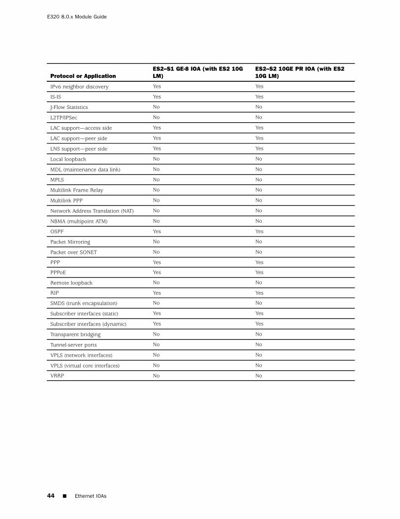
Ethernet IOAs
Table 14: Ethernet IOAs with ES2 4G LM
Protocol or ApplicationES2–S1 GE-4 IOA (withES2 4G LM)
ES2–S1 GE-8 IOA (withES2 4G LM)
ES2–S1 10GE IOA (withES2 4G LM)
Accepts traffic destined forGRE tunnels or DVMRP(IP-in-IP) tunnels
Yes Yes Yes
APS/MSP No No No
ATM No No No
BERT No No No
BGP Yes Yes Yes
BGP/MPLS VPNs Yes Yes Yes
Bridged Ethernet No No No
Bridged IP No No No
Ethernet IOAs 39
E320 8.0.x Module Guide
Protocol or ApplicationES2–S1 GE-4 IOA (withES2 4G LM)
ES2–S1 GE-8 IOA (withES2 4G LM)
ES2–S1 10GE IOA (withES2 4G LM)
CBF No No No
Cisco HDLC No No No
DHCP external server Yes Yes Yes
DHCP local server Yes Yes Yes
DVMRP and GREsupport—access side
Yes Yes Yes
DVMRP and GREsupport—server side
Yes (over shared tunnelserver ports)
Yes (over shared tunnelserver ports)
Yes (over shared tunnelserver ports)
Dynamic interfaces Yes Yes Yes
F4 OAM and F5 OAM (ATMadministration)
No No No
FDL (facilities data link) No No No
Firewall No No No
Frame Relay No No No
IEEE 802.3ad linkaggregation
Yes Yes No
IP Yes Yes Yes
IP multicast Yes Yes Yes
IP reassembly for tunneledpackets
Yes Yes Yes
IPSec No No No
IPv6 Yes Yes Yes
IPv6 multicast Yes Yes Yes
IPv6 neighbor discovery Yes Yes Yes
IS-IS Yes Yes Yes
J-Flow Statistics Yes Yes Yes
L2TP/IPSec No No No
LAC support—access side Yes Yes Yes
LAC support—peer side Yes Yes Yes
LNS support—peer side Yes Yes Yes
Local loopback No No No
MDL (maintenance data link) No No No
MPLS Yes Yes Yes
Multilink Frame Relay No No No
Multilink PPP No No No
Network Address Translation(NAT)
No No No
NBMA (multipoint ATM) No No No
40 Ethernet IOAs
IOA Protocol Support
Protocol or ApplicationES2–S1 GE-4 IOA (withES2 4G LM)
Accepts traffic destined for GRE tunnels or DVMRP (IP-in-IP)tunnels
No
APS/MSP No
ATM No
BERT No
BGP Yes
BGP/MPLS VPNs Yes
Bridged Ethernet No
Bridged IP No
CBF No
Cisco HDLC No
DHCP external server No
DHCP local server No
DVMRP and GRE support—access side No
DVMRP and GRE support—server side Yes (over dedicated tunnel server ports)
Dynamic interfaces No
F4 OAM and F5 OAM (ATM administration) No
FDL (facilities data link) No
Firewall No
Frame Relay No
IEEE 802.3ad link aggregation No
IP Yes
IP multicast No
IP reassembly for tunneled packets Yes
IPSec No
IPv6 No
IPv6 multicast Yes
IPv6 neighbor discovery No
IS-IS Yes
J-Flow Statistics Yes
L2TP/IPSec No
LAC support—access side No
LAC support—peer side No
LNS support—peer side Yes
Service IOA 49
E320 8.0.x Module Guide
Protocol or Application ES2–S1 SERVICE IOA
Local loopback No
MDL (maintenance data link) No
MPLS Yes
Multilink Frame Relay No
Multilink PPP Yes (with fragmentation and reassembly; dynamic only)
Network Address Translation (NAT) No
NBMA (multipoint ATM) No
OSPF Yes
Packet Mirroring No
Packet over SONET No
PPP No
PPPoE No
Remote loopback No
RIP Yes
SMDS (trunk encapsulation) No
Subscriber interfaces (static) Yes (over GRE tunnels only)
Subscriber interfaces (dynamic) Yes (over GRE tunnels only)
Transparent bridging No
Tunnel-server ports Yes (dedicated only)
VPLS (network interfaces) No
VPLS (virtual core interfaces) Yes
VRRP No
50 Service IOA
Appendix B
Slot Combinations
This appendix lists the IOA slot combinations and contains the following sections:
IOA Slot Combinations on page 51
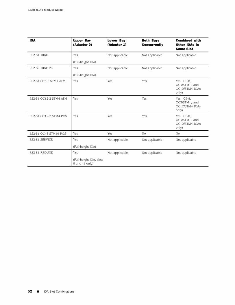
IOA Slot Combinations
Depending on the software release and IOA type, you must install IOAs in certainslots and bays combined with other IOAs in the same slot:
You must insert some IOAs only in the upper bay (Adapter 0) of each IOAmodule slot. If you insert one of these IOAs into a lower bay slot, the linemodule diagnostics fail, an error message states that the bottom slot is notsupported for the currently installed software release, and the slot is disabled.
If you insert an unrecognized IOA, such as an IOA that is not supported bya particular software release, the line module diagnostics fail, an error isgenerated, and the slot is disabled.
If you remove an IOA and replace it with a different IOA in the same slot, anerror message states the mismatch and the slot is disabled.
Full-height IOAs take up the entire slot (both Adapter 0 and Adapter 1).
For information about working with modules and IOAs, see JUNOSe System BasicsConfiguration Guide, Chapter 6, Managing Modules. See Table 20 for currentlyavailable IOAs and the bays in which you may insert them.
Product Reclamation and Recycling Program on page 55
Product Reclamation and Recycling Program
Juniper Networks is committed to environmentally responsible behavior. As part ofthis commitment, we continually work to comply with environmental standardssuch as the European Union’s Waste Electrical and Electronic Equipment (WEEE)Directive and Restriction of Hazardous Substances (RoHS) Directive.
These directives and other similar regulations from countries outside the EuropeanUnion regulate electronic waste management and the reduction or elimination ofspecific hazardous materials in electronic products. The WEEE Directive requireselectrical and electronics manufacturers to provide mechanisms for the recycling andreuse of their products. The RoHS Directive restricts the use of certain substancesthat are commonly found in electronic products today. Restricted substancesinclude heavy metals, including lead, and polybrominated materials. The RoHSDirective, with some exemptions, applies to all electrical and electronic equipment.
In accordance with Article 11(2) of Directive 2002/96/EC (WEEE), products put onthe market after 13 August 2005 are marked with the following symbol or include itin their documentation: a crossed-out wheeled waste bin with a bar beneath.
Juniper Networks provides recycling support for our equipment worldwideto comply with the WEEE Directive. For recycling information, go tohttp://www.juniper.net/environmental, and indicate the type of Juniper Networks
Product Reclamation and Recycling Program 55
E320 8.0.x Module Guide
equipment that you wish to dispose of and the country where it is currentlylocated, or contact your Juniper Networks account representative.
Products returned through our reclamation process are recycled, recovered, ordisposed of in a responsible manner. Our packaging is designed to be recycled andshould be handled in accordance with your local recycling policies.
Juniper Networks, the Juniper Networks logo, NetScreen, and ScreenOS are registered trademarks of Juniper Networks, Inc. in theUnited States and other countries. JUNOS and JUNOSe are trademarks of Juniper Networks, Inc. All other trademarks, service marks,registered trademarks, or registered service marks are the property of their respective owners.
Juniper Networks assumes no responsibility for any inaccuracies in this document. Juniper Networks reserves the right tochange, modify, transfer, or otherwise revise this publication without notice.
Products made or sold by Juniper Networks or components thereof might be covered by one or more of the following patents that areowned by or licensed to Juniper Networks: U.S. Patent Nos. 5,473,599, 5,905,725, 5,909,440, 6,192,051, 6,333,650, 6,359,479, 6,406,312,6,429,706, 6,459,579, 6,493,347, 6,538,518, 6,538,899, 6,552,918, 6,567,902, 6,578,186, and 6,590,785.