MASTER XL PARALLEL GEARMOTORS AND C-FACE REDUCERS ® SERVICE AND REPAIR FOR SIZES 16, 21, 28 WARNING: Because of the possible danger to person(s) or property which may result from improper use of products, it is important that correct procedures be followed. Products must be used in accordance with the Engineering information specified in the catalog. Proper installation, operation and maintenance procedures must be observed. The instructions in the instruction manuals must be followed. Inspections should be made as necessary to assure safe operation under prevailing conditions. Proper guards and other suitable safety devices or procedures as may be desirable or as may be specified in safety codes should be provided, and are neither provided by Master Power Transmission nor are the responsibility of Master Power Transmission. This unit and its associated equipment must be installed, adjusted and maintained by qualified personnel who are familiar with the construction and operation of all the equipment in the system and the potential hazards involved. When risk to persons or property may be involved, a failsafe device must be an integral part of the driven equipment beyond the speed reducer output shaft. 3300 Tenth St. / Columbus, IN 47201 / (812) 376-1100 www.master-pt.com Master XL Parallel instruction Manual E-3607-16 4/2010 INSTRUCTION MANUAL E-3607-16
Transcript
MASTER XL PARALLEL GEARMOTORS
AND C-FACE REDUCERS
®
SERVICE AND REPAIR
FOR SIZES 16, 21, 28
WARNING: Because of the possible danger to person(s) or property which may result from improper use of products, it is important that correct
procedures be followed. Products must be used in accordance with the Engineering information specified in the catalog. Proper installation, operation
and maintenance procedures must be observed. The instructions in the instruction manuals must be followed. Inspections should be made as
necessary to assure safe operation under prevailing conditions. Proper guards and other suitable safety devices or procedures as may be desirable or
as may be specified in safety codes should be provided, and are neither provided by Master Power Transmission nor are the responsibility of Master
Power Transmission. This unit and its associated equipment must be installed, adjusted and maintained by qualified personnel who are familiar with the
construction and operation of all the equipment in the system and the potential hazards involved. When risk to persons or property may be involved, a
failsafe device must be an integral part of the driven equipment beyond the speed reducer output shaft.
3300 Tenth St. / Columbus, IN 47201 / (812) 376-1100
MAINTENANCE Removal of Motor ................ ....................................................................................... 7 Disassembly and Reassembly of Single Parallel Gearmotors and Reducers ............. 9 Disassembly and Reassembly of Double Parallel Gearmotors and Reducers ......... .10 Disassembly and Reassembly of Triple Parallel Gearmotors and Reducers ............ 11 Replacement Part Numbers for Single Parallel Gearmotors and Reducers ............. 12 Parts List Drawing for Single Parallel Gearmotors and Reducers ................. .......... 13 Replacement Part Numbers for Double Parallel Gearmotors and Reducers ............ 14 Parts List Drawing for Double Parallel Gearmotors and Reducers .......................... 15 Replacement Part Numbers for Triple Parallel Gearmotors and Reducers .............. 16 Parts List Drawing for Triple Parallel Gearmotors and Reducers ............................ 18 Long-Term Storage ........................................................................... .. ...................... 19 Hardware Torques ............................................ ......................................................... 20 Renewal Parts .......................................... .. .. .................................... .......................... 20
-2-
tchute
Typewritten Text
tchute
Typewritten Text
tchute
Typewritten Text
Click on the page number to navigate
MOUNTING, LUBRICATION, AND MAINTENANCE INFORMATION GEARCASE MOUNTING
GENERAL The MASTER Parallel Gear line is composed of one basic
reducer. This reducer is used to make up two types of motor and gear reduction packages.
1. THE GEARMOTOR - is a compact integral power package. Partial motor is directly connected to the reducer input shaft by means of a semi-rigid coupling.
2. THE C-FACE REDUCER - is also a compact power package utilizing a standard "C" Face motor, adapter, and flexible coupling connecting to the reducer.
The MASTER Parallel gearing is Helical design with ball bearings on input shaft and taper roller bearings on intenne-diate and output shafts.
ROTATION To reverse the direction of rotation of a 3-phase A-C
Geannotor, interchange any two of the lines going to the motor. If it is a 2-phase geannotor, interchange the wires of one phase. Four wire 2-phase geannotors have lead marking confonning to NEMA standards.
D-C Geannotors may be reversed by interchanging the armature leads (AI and A2). In all cases, the connection diagrams furnished with the motors must be consulted to insure that proper polarity of series fields is retained.
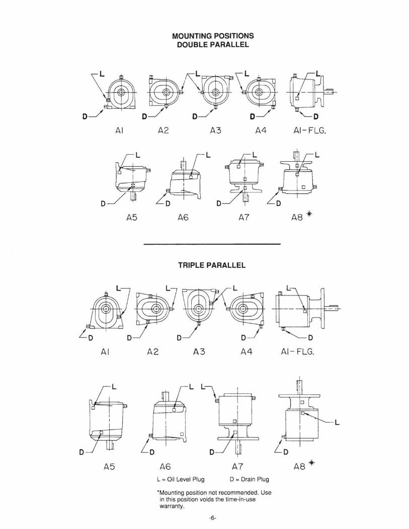
GEARCASE MOUNTING This gearcase has been lubricated at the factory for only one
mounting position. Before starting, check the following mount-ing position diagrams to make sure that the oil level plug and oil level are in the correct location for which the unit is to be operated. This is extremely important as insufficient lubricant will damage gears and bearings in a very short time. When the unit is to be mounted in a position other than those shown in the diagrams, consult factory.
OPERATING TEMPERATURES Heating is a natural characteristic of high speed gears and
a maximum gearcase sump temperature approaching 200°F. is not uncommon for units operating in nonnal ambient temperatures. When operated at rated capacity, no damage will result from this temperature as this was taken into consid-eration in the design of the gearcase and the selection of the lubricants.
INST ALLATION The gear unit must be mounted on a sturdy base of sufficient
strength to prevent distortion due to applied loads. To prevent the introduction of additional stresses in the gear unit, the base must be flat and any uneveness must be compensated for by the insertion of shims between the base and the feet of the gearcase. Hex head bolts of proper diameter, together with flat washers, should be used to mount the gear unit to its base.
MAINTENANCE Geannotors and gear reducers are accurately adjusted and
tested at the factory. Care must be taken when the gearcase is
-3-
disassembled and reassembled. This should be done by an authorized service station as damage to internal parts may result if done improperly.
Whenever a partial motor is assembled to the gearcase of a geannotor -type unit, the spline on the reducer input shaft must be lubricated with a molydisulfide type lubricant, preferably Mobiltemp No. 78 grease.
Whenever a C-face motor is assembled to a C-face-type reducer, care must be taken to ensure that the flexible coupling hub on the motor shaft is spaced properly from the end of the motor shaft. See diagram on page 8 of this manual.
SERVICE CLASSES OR SERVICE FACTORS Load conditions must be in accordance with service class or
service factor as listed on the name plate. Parallel geannotors have service classes, while parallel reducers have service factors. Refer to the Reliance Electric catalog or AGMA published ratings for definition of service conditions.
LUBRICATION INFORMATION Lubrication is extremely important for satisfactory opera-
tion. Proper oil level must be maintained in the gearcase at all times. The correct level is indicated by the red pipe plug. Frequent inspections with the unit not running, (preferably when wann) , should be made by removing this plug to see that the level is being maintained. If low, (without replacing oil level plug), add lubricant through one of the upper holes until it comes out the oil level hole. Replace the oil level plug securely.
The satisfactory perfonnance of gears and bearings in gear motors and reducers depends on clean lubricant, free from dust, grit, sludge, and moisture. Depending on operating conditions, the lubricant will eventually become contami-nated and should be drained periodically. When first put into operation, the lubricant in a new gearcase becomes contami-nated with grit and metal particles unavoidably left in the unit as a result of machining and from tooth surfaces during run-in periods.
Lubricant should be drained, the gearcase flushed with mineral spirits, and refilled after the first 250 hours of opera-tion; then every 1500 hours or six months thereafter, which-ever occurs first. (Nonnal operation is running 16 hours per day in 80°F. ambient.) More frequent oil changes may be required when running continuously at high temperatures. Use only recommended lubricants as listed in the following table.
All bearings above the the operating oil level that are provided with a pipe plug should be lubricated with a good grade of ball bearing grease when changing gear lubricant. (Replace the pipe plug with a zerk fitting at this time.) Do not overlubricate grease packed bearings.
Master XL parallel gear units are factory filled to the proper oil level for position I mounting and an ambient condition of +60°F. to + 110°F. and 13.5 to 500 RPM output speed (SAE 40 oil).
RECOMMENDED LUBRICANTS It is impossible to select one gear lubricant of petroleum
origin which is usable over a wide range oftemperatures, such as minus (-) 65°F. to plus (+) 165°F., as is required for some installations. When such conditions are encountered it is necessary to change lubricants depending on the ambient (surrounding air) temperature at the time of operation. Use lubricants of the proper group as outlined in the following table.
APPROVED LUBRICANTS VS AMBIENT CONDITIONS: Ambient Lubricant Viscosity Grade vs . Outputshaft Speed
Temperature 13.5 to 500 501 to 1000 1001 to 3000 Over 3000 RPM RPM RPM RPM
"Mobil SHC 629 is suitable for all speeds in these temperatures.
Note (A) Use automotive heavy duty oil , SAE 50 grade with oxidation inhibitor. Note (8) Use Gulf Paramount No. 22 which is a naphenic base oil with a low pour point and viscosities of. 109:8 SUS at 100°F. or 39.1 SUSat 210°F. Any other oil meeting these specifications would be a sUitable substitute. Note (C) Use Mobil Oil Corp. Avrex 904 oil .
Use only the best grades of automotive engine lubricants unless otherwise specified. When gear units are used out-of-doors, seasonal changes may be necessary.
Do not operate gear unit in ambient temperatures below -65°F. nor above + 165°F. For temperatures below + 100F. special oil seals are required.
When changing oil from one viscosity grade to another, flush the gearcase with mineral spirits before installing the new oil.
If a USDA-HI food grade lubricant is desired, Chevron FM Lubricating Oil 460X may be used in ambient temperatures of +15 °F. to +110°F. If Chevron FM Lubricating Oil 460X is installed in the field by draining a gearcase which contains our standard non food grade lubricant, the gearcase must be flushed thoroughly with mineral spirits before installing the new lubricant.
-4-
WARRANTY This equipment is warranted under Reliance's published
"Standard Terms and Conditions of Sale of Electrical Apparatus."
Parts, service, and repairs, in or out of warranty may be arranged through any Reliance Authorized Service Shop, Distributor, or District Sales Office.
Damage in shipment, abuse, misuse, applicable mainte-nance and repair and periodic adjustments, as required, are not part of this warranty.
STANDARD TERMS & CONDITIONS OF SALE Company expressly warrants the equipment manufactured
by it as set forth herein. Company makes no other warranties, either express or implied (including without limitation warranties as to merchantability or fitness for a particular purpose).
WARRANTY CAUTION: SERVICE AND REPAIR UNDER WARRANTY SHOULD BE PERFORMED ONLY BY A DODGE AUTHORIZED SERVICE SHOP. CALL WARRANTY ADMINISTRA-TION AT 812-376-1100 FOR THE NEAREST LOCATION.
MASTER XL gear units are warranted under the DODGE "Standard Conditions for Sale."
Warranty claims on any such apparatus must be submitted to the company within one year from date of installation or within three years from date of manufacture, whichever comes first. The Seller's warranty applies insofar as the equipment is operated within the rating and service conditions for which it was specifically sold. The warranty does not extend to failures induced by misuse, improper storage or handling, abuse or misapplication.
For warranty service, contact the nearest DODGE Sales Office or Authorized Distributor or call Warranty Adminis-tration at 812-376-1100.
;/-.-~-.~
(~\ ~.~ - .-1- - r j,.
';:1 ; I . .\;'
\!, 1- .. _ij/ !.
D\~-lJ/ c.J.-~-
=1
;;-~!
ml1 L' / '- - -
C 4 1).
&1 ,Fill
\ I \ I
;;:: ~ LEVEL DRAIN
POSITION C1
~FILL
LEVEL ~~'~ 1/
DR AIN
SM ' 5 .~
MOUNTING POSITIONS SINGLE PARALLEL
rT;':~~ '(' , I .-- -. .. I /. i~
.{ " \ 'I ~~-G--L f ,
~~ IJ [2'
i\ 1 L=-+-~~===t - '_ ... , ... _-
~'-·T .. ; I I J
~-T-~:----' ---.·~7
fIT :-L [5
LEVEL
POSITI ON C2 Stv15F
POSITION C4 SM'5F POSITION C5 SM15F
L = Oil Level Plug D = Drain Plug
-Mounting position not recommended. Use in this position voids the time-in-use warranty.
-5-
f7;+-~ , . ~, rt9-nYL
I I .. ~ -T- - ~. .. .. .. I " ~~ ,
i _~_:/ D-""
[3
III ' I
~-~~ D\l-----J~--J-_1
~ . \ I
c-,----l ~;t-iJ \ .1
*[6
§1FILL
..... -- ......
r' I \
I ! _' LEVEL
DRAIN
POSITION C3 SM15F
FI LL
LEVEL
DRAIN
*POSITION C6 "~OT RECOMMi=:'\;DED SM16F
AI
A5
AI
D
A5
A2
A2
A6
MOUNTING POSITIONS DOUBLE PARALLEL
A3
L
o A6 A7
TRIPLE PARALLEL
A3 A4
o
A7
A4
L = Oil Level Plug D = Drain Plug
*Mounting position not recommended. Use in this position voids the time-in-use warranty.
-6-
AI- FLG.
"--0 AI- FLG.
A8 "*
L
REMOVAL OF INTEGRAL MOTOR
WARNING To ensure that drive is not unexpectedly started, tum off and lock out or tag power source before proceeding. Failure to observe these precautions could result in bodily injury.
For the Gearmotor Configuration: 1. Disconnect all electrical wire and conduit. 2. Remove four motor bolts (6). 3. Tap the side of the end shield (3) to loosen and remove. 4. Remove stator and frame assembly (4). 5. Rotor and shaft assembly (5) will now slide off of the
splined input shaft. Be careful not to lose the coupling spring (8) which is in the coupling bore.
6. After other repairs are made to the reducer the motor can be assembled in reverse order.
7. The semi-rigid coupling in gearmotors requires a small amount of Mobiltemp 78 lubricant added to the splines.
For the C-Face Configuration: 1. Disconnect all electrical wire and conduit. 2. Remove four motor mounting bolts (76). 3. Pull motor from C-face adaptor. 4. Refer to applicable motor instruction manual if further
disassembly is required.
MOTOR PARTS IDENTIFICATION
1. Thrust Spring 2. Ball Bearing 3. F.E. Shield 4. Stator and Frame 5. Rotor 6. Motor Bolts 7. Motor Shaft and Semi-Rigid
Coupling Assembly 8. Spring (Coupling)
72. Half Coupling for Motor Shaft 73. & 75. Coupling Sleeve or Spider 74. Half Coupling for Reducer
Input Shaft 76. Motor Mounting Bolts
PARTIAL MOTOR USED ON GEARMOTORS
I
I I I I L _ - -'-------''------''-L-----L-.L-.L--L-~~.
MOTOR ADAPTER USED ON C-FACE REDUCERS
-7-
I
" I '~
180TC I 210TC FRAME
INSTALLATION OF MOTOR FOR THE C-FACE CONFIGURATION
WARNING To ensure that drive is not unexpectedly started, tum off and lock out or tag power source before proceeding. Failure to observe these precautions could result in bodily injury.
When the C-face MASTER SPEED REDUCER is re-ceived the adapter is bolted to the gearcase. The flexible coupling assembly and bolts for attaching the motor to the adapter are packaged separately. To assemble the C-face motor to the C-face reducer proceed as follows:
MOTOR FRAMES 48Y, S6C AND 140TC Shown in Figure I below is the C-FACE ASSEMBLY for
mounting Nema C-face motor frames 48Y, 56C, and 140TC. 1. Locate motor coupling hub A on the motor shaft as shown
in figure 2 below. Once located, tighten coupling hub set screw.
2. Slip reducer coupling hub C on the reducer input shaft until it shoulders on the reducer seal sleeve as shown in figure 1.
3. Slip coupling sleeve B over reducer coupling hub C until shouldered.
4. Guide motor shaft coupling hub A into the coupling sleeve as shown in figure 1.
5. Rotate motor to line up C-face tapped holes with bolt holes on the adapter; insert bolts, and tighten securely.
FIGURE 2
FIGURE
0- FROM EN 0 OF HUB TO END OF SHAFT
"C" FACE FRAME
MOTOR FRAMES 180TC - 210TC Shown in the figure below is the C-FACE ASSEMBL Y for
mounting Nema C-face motor frames 180TC and 2IOTC. 1. Slip reducer coupling hub C on the reducer input shaft until
it shoulders on the reducer seal sleeve. Once located, tighten set screws.
2. Slip motor coupling hub A on motor shaft until the end of the motor shaft is flush with the inner face of the coupling hub. Once located, tighten set screws.
3. Slip coupling spider onto reducing coupling hub C. 4. Guide motor shaft with coupling hub A into spider as
shown below. 5. Rotate motor to line up C-face tapped holes with bolt holes
on adapter, insert bolts, and tighten securely.
NEMA lie" MOTOR
,L~~ ~~ ?
I I
I 11I--~~A n-- ..... ~""""'-----~ l ~ } I L_
MASTER GEAR REDUCER
LUBRICATION AND MAINTENANCE The C-face MASTER SPEED REDUCER flexible cou-
pling is lubrication free and requires no maintenance.
D
56 FR. OR 48 FR. WITH
56 FR. "C" FACE 1/8
140TC 1/8
-8-
INSTRUCTIONS FOR DISASSEMBLY AND RASSEMBLY OF SINGLE PARALLEL GEARMOTORS AND REDUCERS (Refer to Pages 12 & 13)
WARNING To ensure that drive is not unexpectedly started, turn off and lock out or tag power source before proceeding. Failure to observe these precautions could result in bodily injury.
1. Remove motor if complete disassembly is to be made.
2. Remove the drain plug and drain the oil from the reducer.
3. Remove the screws holding the bearing housing (8) in place and tap housing with a mallet to separate at the gasket joint. Remove the bearing housing from the gearcase (6) making sure that the gear is not hit or damaged in any way. Remove the output shaft (17) and driven gear-assembly (10) from the gearcase.
4. To remove the input shaft, remove the seal clamp screws and seal clamp (3). Tap the opposite end of the input shaft with a mallet in order to force out the shaft seal (4) and bearing (Sa) from the gearcase. On gearmotors where a lockring is used to secure the bearing and seal in the gearcase, Tru-arc pliers can be used to remove this lockring. If bearings and gears are to be replaced, a suitable set of bearing pullers or an arbor press should be utilized to remove them.
5. To remove the driven gear (10) from the output shaft (17), place the assembly in a press with the shaft down resting on the gear. Press the shaft out of the gear (10), spacer collar (13), and bearing (31a). On S-16 reducers, a lockring (43) serves as a shoulder and care should be taken not to try and press against it. Reverse shaft in the press and press other bearing (31 b) off of shaft. All parts and castings should now be washed and inspected for replacements.
6. Re-assemble in reverse order. If bearings or gears have been removed from the shafts, they should now be replaced with new ones.
7. Install spacer (44). Press the driven gear (10) on the output shaft (17) install spacer (13) and bearing (31a).
*Grease Retainer (34) used only in vertical output shaft up mounting position.
9. Install the bearings (5a-5b) on the input shaft (1). Also press on the seal sleeve (2) applying a small amount of sealer under the sleeve.
NOTE: In S-28 reducers, some ratios have a shell pinion (37) on the input shaft. There are spacers (36 & 38) and a lockring (42) on the input shaft ..
10. The input shaft (l) should be installed in the gearcase before the output shaft (17).
11. Apply a small amount of lubricant to the input shaft seal (4) a-Ring and seal sleeve (2). This will allow the seal to slide into the gearcase bore more freely. Install the seal clamp (3) and screws and tighten.
12. If the unit is a gearmotor with a lockring, add ball bearing shims as required between the lockring and the seal housing to limit the endplay of the input shaft to the internal clearance of the ball bearing.
13. The taper roller bearing cups (31a-31b) should be placed in the bearing bore of gearcase (6) and bearing housing (8). Shim to ..001. Shimming of the roller bearings is done by means of bearing shims (14) of various thicknesses. These shims are placed under the bearing cup in the bearing housing (8).
14. Place the output shaft with gear in gearcase carefully. Install the bearing housing gasket with sealer, bearing housing and secure with several bolts. When shimmed properly, there should be no side movement in the bearings or final output shaft, and the bearings should not be preloaded.
15. The output shaft seal (15) should be the last part installed in the bearing housing (8). A small amount of sealer should be placed on the outside diameter of the seal. Start the seal into the bore and tap into place, using a tube of the correct diameter so as to be able to tap the seal into place flush with the face of the bearing housing. Fill the gearcase with the proper lubricant to the correct oil level for test.
16. Reinstall motor.
-9-
tchute
Typewritten Text
tchute
Typewritten Text
tchute
Typewritten Text
tchute
Typewritten Text
tchute
Typewritten Text
tchute
Typewritten Text
tchute
Typewritten Text
tchute
Typewritten Text
tchute
Typewritten Text
tchute
Typewritten Text
tchute
Typewritten Text
tchute
Typewritten Text
tchute
Text Box
tchute
Typewritten Text
tchute
Typewritten Text
tchute
Typewritten Text
tchute
Typewritten Text
tchute
Typewritten Text
tchute
Typewritten Text
tchute
Typewritten Text
tchute
Text Box
tchute
Typewritten Text
tchute
Typewritten Text
.001 - .003
tchute
Typewritten Text
tchute
Typewritten Text
tchute
Typewritten Text
INSTRUCTIONS FOR DISASSEMBLY AND REASSEMBLY OF DOUBLE PARALLEL GEARMOTORS AND REDUCERS (Refer to pages 14 & 15)
WARNING To ensure that drive is not unexpectedly started, turn off and lock out or tag power source before proceeding. Failure to observe these precautions could result in bodily injury.
1. Remove motor.
2. Remove the drain plug and drain the lubricant from the gearcase. We suggest that the disassembly of a gear-motor or a reducer begin at the input shaft of the unit.
3. The input shaft seal (4) and bearing (Sa) were locked in the coverplate (7) by a lockring in earlier designs. The present design input shaft seal and bearing are locked with a clamp (3) and screws.
4. Remove the bolts holding the coverplate and tap the cover to loosen at the gasket fit. The coverplate (7) and input shaft (1) can be removed as an assembly, being careful not to hit or damage the gear teeth. Remove the clamp (3) and pull or tap the input shaft 0), seal (4), and bearing (Sa) from the coverplate.
5. Remove the screw (11) and washer (12) holding the first stage driven gear (0) on the second stage pinion shaft (19). This gear should come off freely.
6. Stand gearcase on end with the output shaft vertically up. Remove the bolts holding the bearing housing (8). Tap the side of the housing to loosen at the gasket fit. Lift off the bearing housing.
7. The final output shaft (17) assembly can now be removed. The second stage pinion shaft (19) can now also be removed.
8. All parts and castings should now be washed and inspected for possible replacements. If parts are replaced, reshim bearings for proper fit up.
9. Reassemble in reverse order. It is a good idea to shim the shafts separately, in that installing each shaft and checking for pre loading gives the best results. Install the final output shaft assembly (17) in the gearcase. The bearing shims are placed under the bearing cup in the bearing housing (8). Shim to .000-.003 endplay. Install the gasket and bearing housing (8), and secure with several screws. Check this shaft for proper shimming to be sure that there is no side motion and that the shaft turns freely.
-10-
10. Remove bearing housing (8) and the final output shaft assembly (17).
11. Install the second stage pinion shaft (19). Shims (18) are placed under the bearing cup (9b) in the bearing housing (8). Place the bearing housing on the gearcase with a gasket and several screws. Check the shaft from the inside of the gearcase making sure that the shaft turns freely and that there is no side motion in the bearings (9a-9b). Shim to .000-.003 endplay.
12. Remove the bearing housing (8) and place the final output shaft (17) back into the gearcase again. Place some sealer on the gasket surface and reinstall the bearing housing using all screws. At this time install the counter shaft oil seal (15) in the bearing housing.
13. Place the gearcase on its feet again and install the first stage driven gear (10) on the second stage pinion shaft (19). Lock in place with washer (12) and screw (11).
14. If new ball bearings (5a-5b) have been installed on the input shaft (1), a new seal sleeve (2) should also be installed. Apply some sealer to the shaft at the seal sleeve location.
NOTE: On D-16 and D-21 size reducers, the pinion is cut on the input shaft. In D-28 reducers, some ratios have a shell pinion (37) on the input shaft. There are spacers (36 & 38) and a lockring (39) on this input shaft.
* Grease retainer (34) used only in vertical output shaft up mounting position.
15. The input shaft (1) is placed in the coverplate (7). A bit of lubricant applied to the seal sleeve (2) will make installation easier.
16. Place the oil seal assembly (4) in the coverplate (7). A bit of lubricant applied to the seal sleeve (2) and the 0-Ring of the seal will make installation easier. Install the bearing clamp and screws.
17. Fill the reducer with the proper lubricant to the correct oil level for test. Reinstall motor.
tchute
Typewritten Text
tchute
Typewritten Text
tchute
Typewritten Text
tchute
Typewritten Text
tchute
Typewritten Text
tchute
Typewritten Text
tchute
Typewritten Text
tchute
Typewritten Text
tchute
Typewritten Text
tchute
Typewritten Text
tchute
Typewritten Text
tchute
Typewritten Text
tchute
Typewritten Text
tchute
Sticky Note
Accepted set by tchute
tchute
Typewritten Text
tchute
Typewritten Text
tchute
Text Box
tchute
Typewritten Text
tchute
Typewritten Text
tchute
Text Box
tchute
Typewritten Text
tchute
Typewritten Text
.001 - .003
tchute
Typewritten Text
tchute
Typewritten Text
tchute
Text Box
tchute
Typewritten Text
tchute
Typewritten Text
.001 - .003
tchute
Typewritten Text
tchute
Typewritten Text
INSTRUCTIONS FOR DISASSEMBLY AND REASSEMBLY OF TRIPLE PARALLEL GEARMOTORS AND REDUCERS (Refer to Pages 16, 17 & 18)
WARNING To ensure that drive is not unexpectedly started, turn off and lock out or tag power source before proceeding. Failure to observe these precautions could result in bodily injury.
1. Remove motor.
2. Remove the drain plug and drain the lubricant from the gearcase. It is suggested that disassembly begin at the input shaft end of the reducer.
3. Remove the bolts holding the coverplate and tap cover so as to loosen it at the gasket joint. The coverplate and the input shaft assembly can be removed as a unit. Be careful not to hit or damage the gear teeth. Remove the clamp (3) and tap or pull the pinion shaft (1) bearing (Sa) and seal (4) from the coverplate (7).
4. Remove the screw (11) and washer (12) holding the first stage driven gear (10) on the second stage pinion shaft (19). This gear and spacer (13) should slip off freely.
5. Remove the screw (24) and washer (25) holding the second stage driven gear (20). This gear will not normal-ly come off ofthe shaft until output shaft(17) and bearing housing (8) are removed.
6. Remove the three bolts (21) holding the bearing clamp (22) on the second stage pinion shaft. By moving gear (20) on the third stage pinion shaft, the second stage pinion shaft (19) can now be removed. This shaft assembly should now be pulled out, at the same time one bearing cup and shims will also come out.
7. Loosen all screws on bearing housing (8) and remove all except one on each side to keep output shaft in place. With bearing housing loose you can now reach into the gearcase from opposite end and slip off second stage driven gear (20) and spacer (26) from third stage pinion shaft (29).
8. Stand gearcase on end with output shart vertical. Remove remaining screws and lift off bearing housing. Lift out output shaft assembly (17) also the third stage pinion shaft (29).
9. All parts and castings should be washed and inspected for possible replacement. It is our suggestion that the shimming of bearings be done to one shaft at a time, this allows for better freedom and less possibility of too much preloading or looseness of bearings.
10. If new seals and bearings are being installed, it is a good idea to press on the new seal sleeve. Apply some sealer to the shaft at sleeve location.
11. Install the third stage pinion shaft (29) in the gearcase. Place the shims (28) under the bearing cup (27B) in the bearing housing (8). Install the bearing housing with several bearing housing screws. Check the shaft from the inside of the gearcase for proper shimming of the roller bearings (27 A-B). Shim to .000- .003 endplay. The shaft (29) should be free to tum with no side motion in the bearings.
12. Remove the bearing housing screws, bearing housing and lift out the third stage pinion shaft.
*NOTE: Grease retainer (34) used only in vertical output shaft up mounting only.
13. Place the final output shaft (17) into the gearcase. The bearing shims should be placed under the bearing cup (31B) in the bearing housing (8). Shim to .000- .003 endplay. Install the bearing housing and secure with several screws. Check the output shaft to be sure that the shaft turns freely and there is no side motion in the bearings.
14. Remove the bearing housing (8) again and re-install the third stage pinion shaft (29). NOTE: It is now necessary to place the second stage driven gear (20) and spacer (26) onto the third stage pinion shaft (29) from the input end of the gearcase. Use screw (24) and washer (25) finger tight in order to keep the gear on splined shaft while completing assembly of output shaft end. Apply silicone rubber adhesive to gasket surface and re-install bearing housing with all screws. You should now be able to tum the third stage pinion shaft freely from inside the gearcase.
15. From the input end you can now place the second stage pinion shaft (19) into the bearing bores. You will need to loosen the screw (24) which was finger tight and slide gear (20) on spline in order for bearing on pinion shaft (19) to clear gear and go into bearing bore. To secure these shaft bearings (9A-B) the shims (18) are placed under the bearing clamp (22). Shim to .000- .003 end-play. Again shim so there is no side motion in the bearings and shaft turns freely.
16. Secure the second stage driven gear (20) onto the third stage pinion shaft (29) with screw (24) and washer (25).
17. The first stage driven gear (10) and spacer (13) can now be placed on the second stage pinion shaft (19). Lock this gear on the shaft with screw (11) and washer (12).
-11-
18. If new bearings (SA-B) have been installed on the input shaft (1), a new seal sleeve (2) should also be installed. Apply some sealer to the shaft at the seal sleeve location and press the sleeve in place. The input shaft assembly should be placed in the coverplate (7).
NOTE: In T-28 reducers, some ratios have a shell pinion (37) on the input shaft. There are additional spacers (36-38) and lockring (39) on this input shaft.
19. Apply silicone rubber adhesive to the gasket area. Take input shaft (1) and coverplate assembly and install on gearcase making sure that pinion meshes with driven gear and outboard bearing (5B) slides into the bearing bore properly. Install coverplate screws and secure them.
20. The oil seal assembly (4) can now be placed in the coverplate (7). A bit of lubricant should be applied to the seal sleeves and to the 0-Ring. This will allow the seal to slide into place much easier. Install the seal clamp (3) and secure with clamp screws.
21. If the output shaft oil seal has not as yet been installed, it should now be placed in the bearing housing and a tube of proper dimensions used to tap the seal flush with the casting surface.
22. Fill the reducer with the proper lubricant to the correct oil levels for test. Reinstall motor.
tchute
Typewritten Text
tchute
Typewritten Text
tchute
Typewritten Text
tchute
Typewritten Text
tchute
Text Box
tchute
Typewritten Text
.001 - .003
tchute
Typewritten Text
tchute
Typewritten Text
tchute
Typewritten Text
tchute
Typewritten Text
tchute
Typewritten Text
tchute
Typewritten Text
tchute
Typewritten Text
tchute
Typewritten Text
tchute
Typewritten Text
REF. NO. DESCRIPTION
MASTER X-L GEARMOTORS AND
C-FACE SPEED REDUCERS SINGLE PARALLEL
SIZES SG16, SM16, SG21, SM21, SG28, SM28
QTY. PART NUMBER** EACH RATIO S16 S21 S28
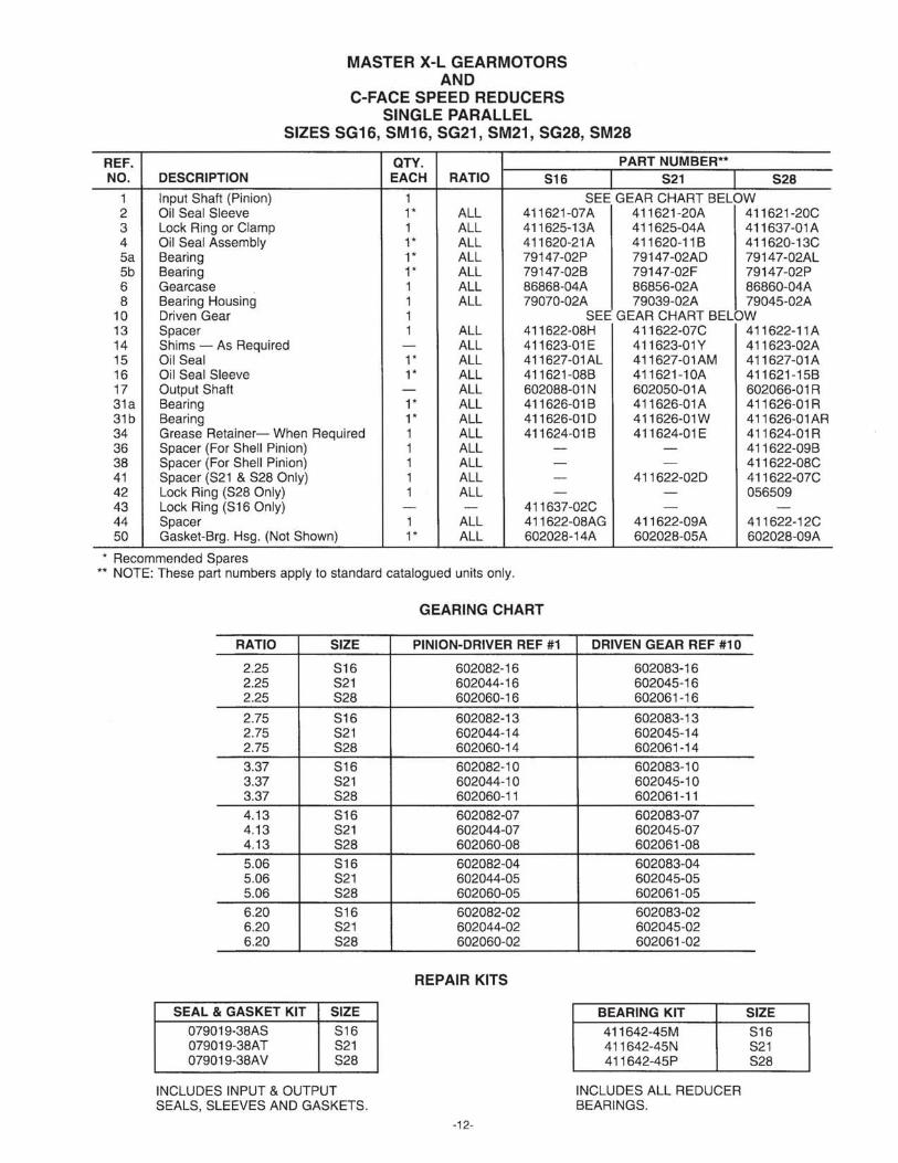
1 Input Shaft (Pinion) 1 SEE GEAR CHART BELOW 2 Oil Seal Sleeve 1* ALL 411621-07A 411621-20A 411621-20C 3 Lock Ring or Clamp 1 ALL 411625-13A 411625-04A 411637-01 A 4 Oil Seal Assembly 1* ALL 411620-21A 411620-11 B 411620-13C 5a Bearing 1* ALL 79147-02P 79147-02AD 79147-02AL 5b Bearing 1* ALL 79147-02B 79147-02F 79147-02P 6 Gearcase 1 ALL 86868-04A 86856-02A 86860-04A 8 Bearing Housing 1 ALL 79070-02A 79039-02A 79045-02A
10 Driven Gear 1 SEE GEAR CHART BELOW 13 Spacer 1 ALL 411622-08H 411622-07C 411622-11A 14 Shims - As Required - ALL 411623-01 E 411623-01Y 411623-02A 15 Oil Seal 1* ALL 411627-01 AL 411 627-01 AM 411627-01A 16 Oi I Seal Sleeve 1* ALL 411621-08B 411621-10A 411621-158 17 Output Shaft - ALL 602088-01 N 602050-01 A 602066-01 R 31a Bearing 1* ALL 411626-01 B 411626-01 A 411626-01 R 31b Bearing 1* ALL 411626-010 411626-01W 411626-01 AR 34 Grease Retainer- When Required 1 ALL 411624-01B 411624-01 E 411624-01 R 36 Spacer (For Shell Pinion) 1 ALL - - 411622-09B 38 Spacer (For Shell Pinion) 1 ALL - - 411622-08C 41 Spacer (S21 & S28 Only) 1 ALL - 411622-020 411622-07C 42 Lock Ring (S28 Only) 1 ALL - - 056509 43 Lock Ring (S16 Only) - - 411637-02C - -44 Spacer 1 ALL 411622-08AG 411622-09A 411622-12C 50 Gasket-Brg. Hsg. (Not Shown) 1* ALL 602028-14A 602028-05A 602028-09A
* Recommended Spares ** NOTE: These part numbers apply to standard catalogued units only.
INCLUDES INPUT & OUTPUT SEALS, SLEEVES AND GASKETS.
GEARING CHART
PINION-DRIVER REF #1
602082-16 602044-16 602060-16
602082-13 602044-14 602060-14
602082-10 602044-10 602060-11
602082-07 602044-07 602060-08
602082-04 602044-05 602060-05
602082-02 602044-02 602060-02
REPAIR KITS
-12-
DRIVEN GEAR REF #10
602083-16 602045-16 602061-16
602083-13 602045-14 602061-14
602083-10 602045-10 602061-11
602083-07 602045-07 602061-08
602083-04 602045-05 602061-05
602083-02 602045-02 602061-02
BEARING KIT 411642-45M 411642-45N 411642-45P
INCLUDES ALL REDUCER BEARINGS.
SIZE S16 S21 S28
SIZES S16-S21-S28 1. Input Shaft (driver gear) 2. Seal Sleeve 3. Lock Ring or Clamp 4. Oil Seal
Sa. Ball Bearing 5b. Ball Bearing (input shaft)
6. Gearcase B. Bearing Housing
10. 1 st Stage Driven Gear 13. Spacer (gear) 14. Shims 15. Seal (output) 16. Seal Sleeve (output) 17. Output Shaft
31 a. Roller Bearing 31 b. Roller Bearing (output shaft) 34. Grease Retainer (shaft up mounting only) 36. Spacer (liJear) } Shell Pinion 37. Shell Pinion in some S-2B 38. Spacer (gear) Ratios 41. Spacer (bearing) 42. Lock Ring 43. Lock Ring (S-16) 44. Spacer (gear)
816
828
821
-13-
cp \
34
REF. NO.
1 2 3 4 5a 5b 6 7 7 8 9a 9b
10 14 15 16 17 18 19 20 31a 31b 33 34 36
37
38 50
MASTER X-L GEARMOTORS AND
C-FACE SPEED REDUCERS DOUBLE PARALLEL
SIZES DG16, DM16, DG21, DM21, DG28, DM28
QTY. PART NUMBER** DESCRIPTION EACH RATIO 016 021 028 Input Shaft - 1 st stg. Pinion 1 SEE GEAR CHART BELOW Oil Seal Sleeve 1* ALL 411621-07A 411621-20A 411621-20C Clamp 1 ALL 411625-13A 411625-04A 411625-04A Oil Seal Assembly 1* ALL 411620-21A 411620-11 B 411620-13C Bearing (Input Shaft) 1* ALL 79147-02P 79147-02AD 79147-02AL Bearing (Input Shaft) 1* ALL 79147-02B 79147-02F 79147-02P Gearcase 1 ALL 86870-02A 86858-02A 86862-02A Cover Plate - Input 56/140 Frame 1 ALL 79073-04A 79041-02A 79047-02A Cover Plate - Input 180/210 Frame 1 ALL - 79041-02B 79047-04D Bearing Housing - Output 1 ALL 79074-02A 79042-02A 79048-02A Bearing 1 ALL 411626-01B 411626-01 BE 411626-01 AE Bearing 1 ALL 411626-01 D 411626-01 AD 411626-01 AW Gear - 1 st stg. Driven 1 ALL SEE GEAR CHART BELOW Shims - As Required - ALL 411623-01Y 411623-02AD 411623-03A Oil Seal 1* ALL 411627-01AM 411627-01A 411627-01 D Oil Seal Sleeve 1* ALL 411621-10C 411621-13A 411621-18B Output Shaft 1 ALL 602088-02A 602050-02A 602066-02A Shims - As Required - ALL 411623-01A 411623-02D 411623-03E Pinion Shaft - 2nd stg. Driver 1 SEE GEAR CHART BELOW Gear - 2nd stg. Driven 1 SEE GEAR CHART BELOW Bearing (Output Shaft) 1 ALL 411626-01W 411626-01X 411 626-01 A Y Bearing (Output Shaft) 1 ALL 411626-01 A 411626-01 AA 411626-01 AB Key - Gear 050992 057500 050768 Grease Retainer- When Required 1 ALL 411624-01 E 411624-01 F 411624-01X Spacer (For Shell Pinion Only) 1 - - - 411622-09B
31 a. Roller Bearing 31 b. Roller Bearing 33. Key 34. Grease Retainer (shaft up mounting only)* 36. Spacer l Shell pinion 38. Spacer f in some D-28 39. Lock Ring ratios
QTY. PART NUMBERS** DESCRIPTION EACH RATIO T16 T21 Input Shaft - 1 st stg. Pinion 1 SEE GEARING - PAGE 17 Oil Seal Sleeve 1* ALL 411621-07A 411621-20A Clamp 1 ALL 411625-13A 411625-04A Oil Seal Assembly 1* ALL 411620-21 A 411620-11 B Bearing 1* ALL 79147-02P 79147-02AD Bearing 1* ALL 79147-02B 79147-02F Gearcase 1 ALL 86871-02A 86859-02A Cover Plate-Input 56/140 Frame 1 ALL 79073-04A 79041-02A Cover Plate-I nput 180/210 Frame 1 ALL - 79041-04B Bearing Housing - Output 1 ALL 79076-02A 79044-02A Bearing 1 * ALL 411626-01 D 411626-01 BE Bearing 1* ALL 411626-01 B 411626-01 AD Gear - 1 st stg. Driven 1 SEE GEARING - PAGE 17 Screw 1 ALL 411631-01A 411631-01 A Washer 1 ALL 411632-01 B 411692-01 B Spacer 1 AILL 411622-08H 411622-10B Shims - As Required - ALL 411623-02A 411623-03A Oil Seal 1 * ALL 411627-01A 411627-01 D Oil Seal Sleeve 1 * ALL 411621-15D 411621-18A Output Shaft 1 ALL 602088-03A 602050-03A Shims - As Required - ALL 411623-05A 411623-02A Pinion Shaft - 2nd stg. Driver 1 SEE GEARING - PAGE 17 Gear - 2nd stg. Driven 1 SeE GEARING - PAGE 17 Screw 2 ALL 4119631-02A 411631-02A Clamp 1 ALL 411625-09A 411625-09A Spacer (T16 Only) 1 ALL 411622-05A -Screw 1 ALL 411631-01A 411631-01A Washer 1 ALL 411632-01 B 411632-01A Spacer 1 ALL 411622-08G 411622-13A Bearing 1 * ALL 411626-01 B 411626-01 AC Bearing 1 * ALL 411626-01 B 411626-01 AA Shims - As Required - ALL 411623-01 E 411623-02Y Pinion Shaft - 3rd stg. Driver 1 SEE GEARING - PAGE 17 Gear - 3rd stg. Driven 1 SEE GEARING - PAGE 17 Bearing 1* ALL 411626-01 R 411626-01 AB Bearing 1* ALL 411626-01 BC 411626-01Y Spacer (T16 & T28 Only) 1 ALL 411622-10E -Key, Gear 1 ALL 053180 051283 Grease Retainer 1 ALL 411624-01R 411624-01X Spacer (T21 & T28 Only) 1 ALL - 411622-14A Spacer (For Shell Pinion Only) 1 ALL - -Spacer (For Shell Pinion Only) 1 ALL - -Lock Ring (T28 Only) 1 ALL - -Lock Ring (T28 Only) 1 ALL - -Gasket-Not Shown-Input Brg. Hsg. 1* ALL 602028-08C 602028-08C Gasket-Not Shown-Output C. Plate 1* ALL 602028-15A 602028-07A
* Recommended Spares ** NOTE: These part numbers apply to standard catalogued units only.
SEAL & GASKET KIT 07901938BA 07901938BB 07901938BC
INCLUDES INPUT & OUTPUT SEALS, SLEEVES AND GASKETS
32. Spacer (T-16 & T-28) 33. Key 34. Grease Retainer (shaft up mounting only)* 3S. Spacer (T-21 & T-28) 36. Spacer t Shell Pinion 38. Spacer f in some T-28 39. Lock Ring ratios 40. Lock Ring
LONG-TERM STORAGE GUIDELINES FOR GEAR REDUCERS:
Care must be taken to ensure that gear reducers are placed in service in the best possible condition. During periods of long storage (six months or longer) special procedures must be followed which will protect the reducer and make certain that it will be in good condition when ready to be put into service.
By taking special precautions, problems such as seal leak-age and reducer failure due to lack of lubrication, improper lubrication quantity, or contamination can be avoided. The following precautions will protect reducers during periods of long-term storage: A. Preparation:
1. Select a clean, dry, protected storage area free of vibration and temperature extremes. Set the drive level on its feet with no load on either the input or output shafts. Block as needed to keep weight off the motor fan shroud and motor conduit box (if unit has a motor).
2. Fill the gearbox to the highest designated oil level with a recommended lubricant blended with 2% by volume of*Daubert Chemical Co. Nox-RustVCI-105 oil. Do not fill the gearbox completely full of oil. Expansion space is needed to avoid pressurizing the gearbox during temperature variations. Rotate the input shaft at least 60 revolutions to ensure a full distribution of the lubricant.
3. All condensate drains and breathers (on motors so equipped) are to be fully operable to allow breathing through points other than bearing fits. Remove the condensate drain plugs located in the motor end shield. Position the motor so the drain is at the lowest point. Totally enclosed fan cooled XT motors are equipped with automatic drains which should be left in place.
4. All units equipped with heaters must have the heaters connected and operational if the storage conditions are in any way like the anticipated service conditions.
5. Motor windings are to be checked with a megohmeter when the equipment is put into storage. The resistance must be recorded and saved for future reference. See "to put the stored unit into service" forthe megohmeter check required upon removal from storage.
6. Apply a thick coating of chassis-type grease, Cosmoline or equivalent protective coating *(Daubert Chemical Co. Nox-Rust X-110 is a suitable coating) on all unpainted surfaces including threads, bores, keyways and shafts.
7. Apply a thick coating of chassis-type grease to all exposed shaft seals.
8. If the unit must be stored outdoors or in damp or unheated areas indoors, cover the entire exterior with a rust preventative. Seal the unit in a moisture proof container or in an envelope of heavy polyethylene film with a dessicant inside. Shade the enclosure from direct sunlight.
9. Rotate the input shaft at least 60 revolutions once a month to redistribute the lubricant and to prevent brinelling of bearings and drying of seals.
10. Instruction manuals and tags are paper and must be kept dry. Remove these documents and store them in a safe, dry place for future reference at start up.
B. To put the stored unit into service: 1. Remove all protective coatings added for storage.
-19-
2. Drain and refill the gearbox with a recommended type and amount of lubricant. Regreasable assemblies and bearings must be purged and filled with new grease.
3. Install the oil level plug in the proper location for the mounting position to be used. Check the motor conden-sate drain locations to assure the motors will drain properly when mounted in the proposed position. Ro-tate the motor on the gearhead or rotate the motor end shields on the motor frame if necessary to get the drains in the proper positions.
4. Check all hardware for proper tightness. 5. If the gear unit has been stored for more than three years
or in an area with high ambient temperatures, the oil seals must be replaced before being put into service. See the instruction manual for directions on oil seal replacement.
6. Check the motor stator insulation resistance with a megohmeter. Resistance less than one megohm or less than 50% of the resistance reading taken when the motor was put into storage (whichever is the higher resistance), requires the motor winding to be dried in one of the two ways described below. If drying does not restore the winding insulation resistance to the values listed above, the motor must be repaired or rewound. A. Remove the motor from the reducer (see instruction
manual), place the motor in a ventilated oven at not more than 90 degrees celsius (194 degrees F.). Check the insulation resistance every 30 minutes. Bake until the resistance becomes constant.
or B. Lock the motor rotor. Insert a thermocouple in the
winding or set up to measure rise by resistance. Apply low voltage, gradually increase the current through the winding until the winding temperature reaches 90 degrees celsius (194 degrees F.). Do not exceed this temperature. Check the winding insulation resistance with a megohmeter. Repeat if necessary. After drying, briefly run the motor not connected to any load to further dry the motor and to check the bearings for noise and smooth operation.
7. When stored motors are found to be wet, a more detailed inspection should be made by removing the motor end shields and visually inspecting for water in the grease or rust on the bearings. If either is found, replace the bearings, clean the end shields thoroughly and relubricate.
*Note: Daubert Nox-Rust VCI-105 oil and Nox-Rust X-IIO protective coating can be procured in bulk quantity from: Daubert Chemical Company, Inc. 4700 S. Central Ave. Chicago, Illinois 60638 Telephone (708) 496-7350
or in 5-gallon pails from their distributor:
Rock Island Lubricants and Chemicals 1320 First Street Rock Island, Illinois 61204-5015 Telephone (309) 788-5631