10 - S3 - Structural Details 11 - E1 - Electrical Notes 12 - E2 - Electrical Layout 13 - E3 - Elevations-Details-Interconnects 14 - E5 - Power Requirements 01 - C1 - Cover Sheet 02 - C2 - Disclaimer - Site Readiness 03 - A1 - General Notes 04 - A2 - Equipment Layout 05 - A3 - Equipment Details 06 - A4 - Storage & Delivery 07 - M1 - HVAC 08 - S1 - Structural Notes 09 - S2 - Structural Layout ---- ---- SENOGRAPHE PRISTINA MKL GE Healthcare GE does not take responsibility for any damages resulting from changes on drawings made by others. Errors may occur by not referring to the complete set of final issue drawing. GE cannot accept responsibility for any damage due to the partial use of GE final issue drawings, however caused. All dimensions are in millimeters unless otherwise specified. Do not scale from printed pdf files. GE accepts no responsibility or liability for defective work due to scaling from these drawings. /14 EN-MAM-TYP-SENO_PRISTINA-WEB.DWG ---- ---- PMM 5729303-1EN ---- 1/4"=1'-0" ---- 07/Oct/2021 Typical A mandatory component of this drawing set is the GE Healthcare Pre Installation manual. Failure to reference the Pre Installation manual will result in incomplete documentation required for site design and preparation. Pre Installation documents for GE Healthcare products can be accessed on the web at: www.gehealthcare.com/siteplanning - Drawn by Verified by PIM Manual Sheet Format Concession Scale Date File Name Rev S.O. (GON) A3 8 REV DATE MODIFICATIONS FINAL STUDY 01
GE does not take responsibility for any damages resulting from changes on drawings made by others. Errors may occur by not referring to the completeset of final issue drawing. GE cannot accept responsibility for any damage due to the partial use of GE final issue drawings, however caused. Alldimensions are in millimeters unless otherwise specified. Do not scale from printed pdf files. GE accepts no responsibility or liability for defective work
due to scaling from these drawings. /14EN-MAM-TYP-SENO_PRISTINA-WEB.DWG
----
----
PMM 5729303-1EN
----
1/4"=1'-0"
----
07/Oct/2021
Typical
A mandatory component of this drawing set is the GE Healthcare Pre Installation manual. Failure to reference the Pre Installation manual will result inincomplete documentation required for site design and preparation.
Pre Installation documents for GE Healthcare products can be accessed on the web at: www.gehealthcare.com/siteplanning -
Drawn by Verified by PIM Manual
SheetFormat
Concession
Scale DateFile Name
RevS.O. (GON)
A3
8
REV DATE MODIFICATIONS
FINAL STUDY
01
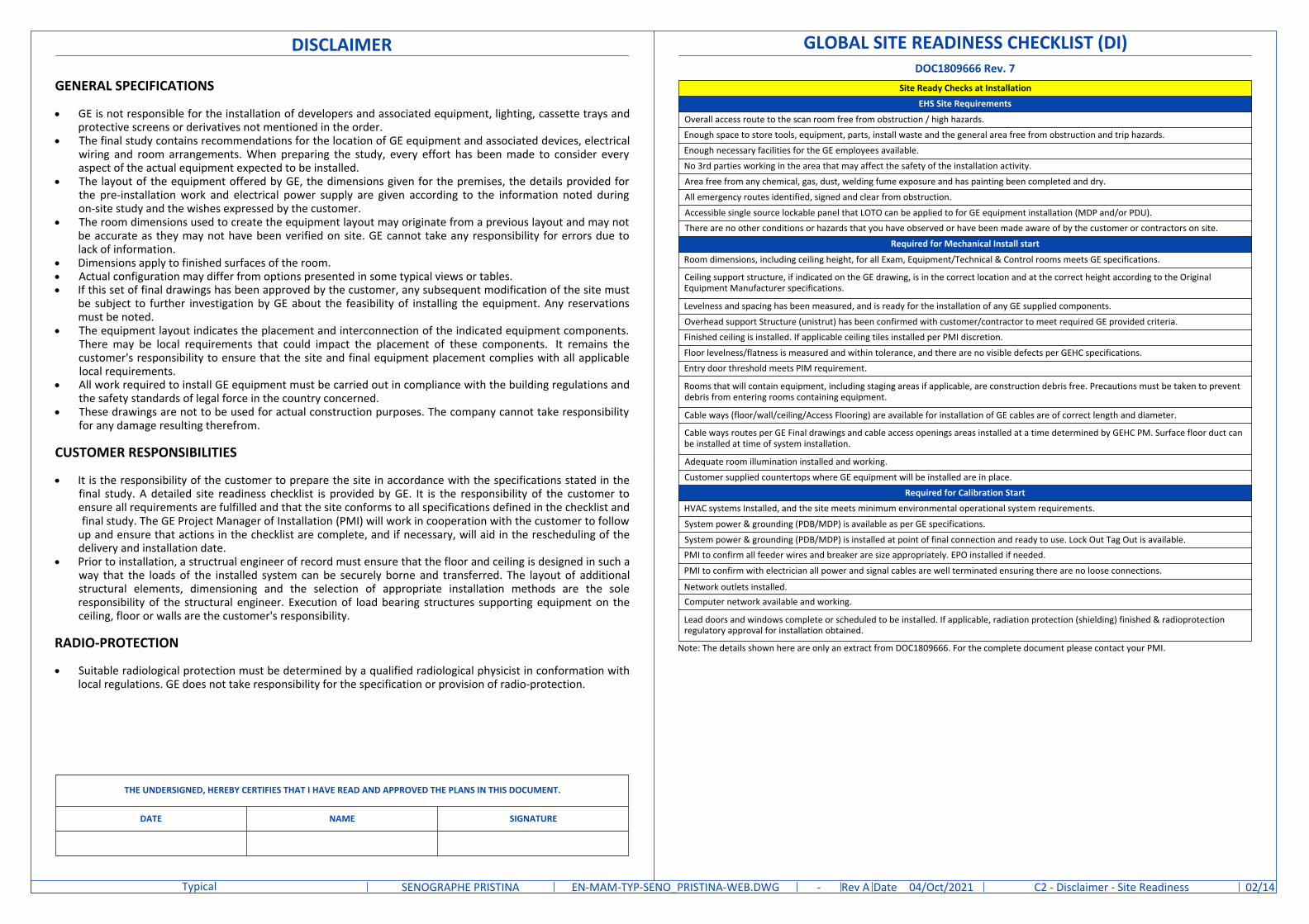
GENERAL SPECIFICATIONS
· GE is not responsible for the installation of developers and associated equipment, lighting, cassette trays andprotective screens or derivatives not mentioned in the order.
· The final study contains recommendations for the location of GE equipment and associated devices, electricalwiring and room arrangements. When preparing the study, every effort has been made to consider everyaspect of the actual equipment expected to be installed.
· The layout of the equipment offered by GE, the dimensions given for the premises, the details provided forthe pre-installation work and electrical power supply are given according to the information noted duringon-site study and the wishes expressed by the customer.
· The room dimensions used to create the equipment layout may originate from a previous layout and may notbe accurate as they may not have been verified on site. GE cannot take any responsibility for errors due tolack of information.
· Dimensions apply to finished surfaces of the room.· Actual configuration may differ from options presented in some typical views or tables.· If this set of final drawings has been approved by the customer, any subsequent modification of the site must
be subject to further investigation by GE about the feasibility of installing the equipment. Any reservationsmust be noted.
· The equipment layout indicates the placement and interconnection of the indicated equipment components. There may be local requirements that could impact the placement of these components. It remains thecustomer's responsibility to ensure that the site and final equipment placement complies with all applicablelocal requirements.
· All work required to install GE equipment must be carried out in compliance with the building regulations andthe safety standards of legal force in the country concerned.
· These drawings are not to be used for actual construction purposes. The company cannot take responsibilityfor any damage resulting therefrom.
CUSTOMER RESPONSIBILITIES
· It is the responsibility of the customer to prepare the site in accordance with the specifications stated in thefinal study. A detailed site readiness checklist is provided by GE. It is the responsibility of the customer toensure all requirements are fulfilled and that the site conforms to all specifications defined in the checklist and final study. The GE Project Manager of Installation (PMI) will work in cooperation with the customer to followup and ensure that actions in the checklist are complete, and if necessary, will aid in the rescheduling of thedelivery and installation date.
· Prior to installation, a structrual engineer of record must ensure that the floor and ceiling is designed in such away that the loads of the installed system can be securely borne and transferred. The layout of additionalstructural elements, dimensioning and the selection of appropriate installation methods are the soleresponsibility of the structural engineer. Execution of load bearing structures supporting equipment on theceiling, floor or walls are the customer's responsibility.
RADIO-PROTECTION
· Suitable radiological protection must be determined by a qualified radiological physicist in conformation withlocal regulations. GE does not take responsibility for the specification or provision of radio-protection.
DISCLAIMER
THE UNDERSIGNED, HEREBY CERTIFIES THAT I HAVE READ AND APPROVED THE PLANS IN THIS DOCUMENT.
DATE NAME SIGNATURE
Site Ready Checks at Installation
EHS Site Requirements
Overall access route to the scan room free from obstruction / high hazards.Enough space to store tools, equipment, parts, install waste and the general area free from obstruction and trip hazards.
Enough necessary facilities for the GE employees available.
No 3rd parties working in the area that may affect the safety of the installation activity.
Area free from any chemical, gas, dust, welding fume exposure and has painting been completed and dry.
All emergency routes identified, signed and clear from obstruction.
Accessible single source lockable panel that LOTO can be applied to for GE equipment installation (MDP and/or PDU).There are no other conditions or hazards that you have observed or have been made aware of by the customer or contractors on site.
Required for Mechanical Install start
Room dimensions, including ceiling height, for all Exam, Equipment/Technical & Control rooms meets GE specifications.
Ceiling support structure, if indicated on the GE drawing, is in the correct location and at the correct height according to the OriginalEquipment Manufacturer specifications.
Levelness and spacing has been measured, and is ready for the installation of any GE supplied components.
Overhead support Structure (unistrut) has been confirmed with customer/contractor to meet required GE provided criteria.Finished ceiling is installed. If applicable ceiling tiles installed per PMI discretion.
Floor levelness/flatness is measured and within tolerance, and there are no visible defects per GEHC specifications.Entry door threshold meets PIM requirement.
Rooms that will contain equipment, including staging areas if applicable, are construction debris free. Precautions must be taken to preventdebris from entering rooms containing equipment.
Cable ways (floor/wall/ceiling/Access Flooring) are available for installation of GE cables are of correct length and diameter.
Cable ways routes per GE Final drawings and cable access openings areas installed at a time determined by GEHC PM. Surface floor duct canbe installed at time of system installation.
Adequate room illumination installed and working.
Customer supplied countertops where GE equipment will be installed are in place.
Required for Calibration Start
HVAC systems Installed, and the site meets minimum environmental operational system requirements.
System power & grounding (PDB/MDP) is available as per GE specifications.
System power & grounding (PDB/MDP) is installed at point of final connection and ready to use. Lock Out Tag Out is available.PMI to confirm all feeder wires and breaker are size appropriately. EPO installed if needed.
PMI to confirm with electrician all power and signal cables are well terminated ensuring there are no loose connections.
Network outlets installed.Computer network available and working.
Lead doors and windows complete or scheduled to be installed. If applicable, radiation protection (shielding) finished & radioprotectionregulatory approval for installation obtained.
GLOBAL SITE READINESS CHECKLIST (DI)DOC1809666 Rev. 7
Note: The details shown here are only an extract from DOC1809666. For the complete document please contact your PMI.
DateRev /14EN-MAM-TYP-SENO_PRISTINA-WEB.DWG A 04/Oct/2021SENOGRAPHE PRISTINATypical C2 - Disclaimer - Site Readiness 02-
ENVIRONMENTAL SPECIFICATIONS
LIGHT REQUIREMENTS
In order to obtain a room brightness value of 100 lux or less for correct viewing of monitor images, the room lightsmust be equipped with a dimmer switch. Shades and/or drapes must be fitted to windows.
SYSTEM NOISE LEVEL
· Gantry: 46 dBA at 1m (3.3 ft)· Control station: 30.1 dBA at 1m (3.3 ft)
ALTITUDE
Operating altitude: from 0 m [0 ft] to 3000 m [9,843 ft].
MAGNETIC INTERFERENCE
In order to avoid interference on the Senographe system, static field limits from the surrounding environment arespecified.· Static field is specified as less than 1 Gauss in the Examination room (Gantry room), and the Control Area
(for all Subsystems).
· Any deviation from these drawings must be communicated in writing to and reviewed by your local GEhealthcare installation project manager prior to making changes.
· Make arrangements for any rigging, special handling, or facility modifications that must be made to deliverthe equipment to the installation site. If desired, your local GE healthcare installation project manager cansupply a reference list of rigging contractors.
· New construction requires the following;1. Secure area for equipment,2. Power for drills and other test equipment,3. Capability for image analysis,4. Restrooms.
· Provide for refuse removal and disposal (e.g. crates, cartons, packing)
· For CT, MR, PET/CT, and SPECT systems it is required to minimize vibrations within the scan room. It is thecustomer's responsibility to contract a vibration consultant/engineer to implement site design modificationsto meet the GE vibration specification. Refer to the system preinstallation manual for vibration specifications.
CUSTOMER SITE READINESS REQUIREMENTS
DateRev /14EN-MAM-TYP-SENO_PRISTINA-WEB.DWG A 04/Oct/2021SENOGRAPHE PRISTINATypical A1 - General Notes 03
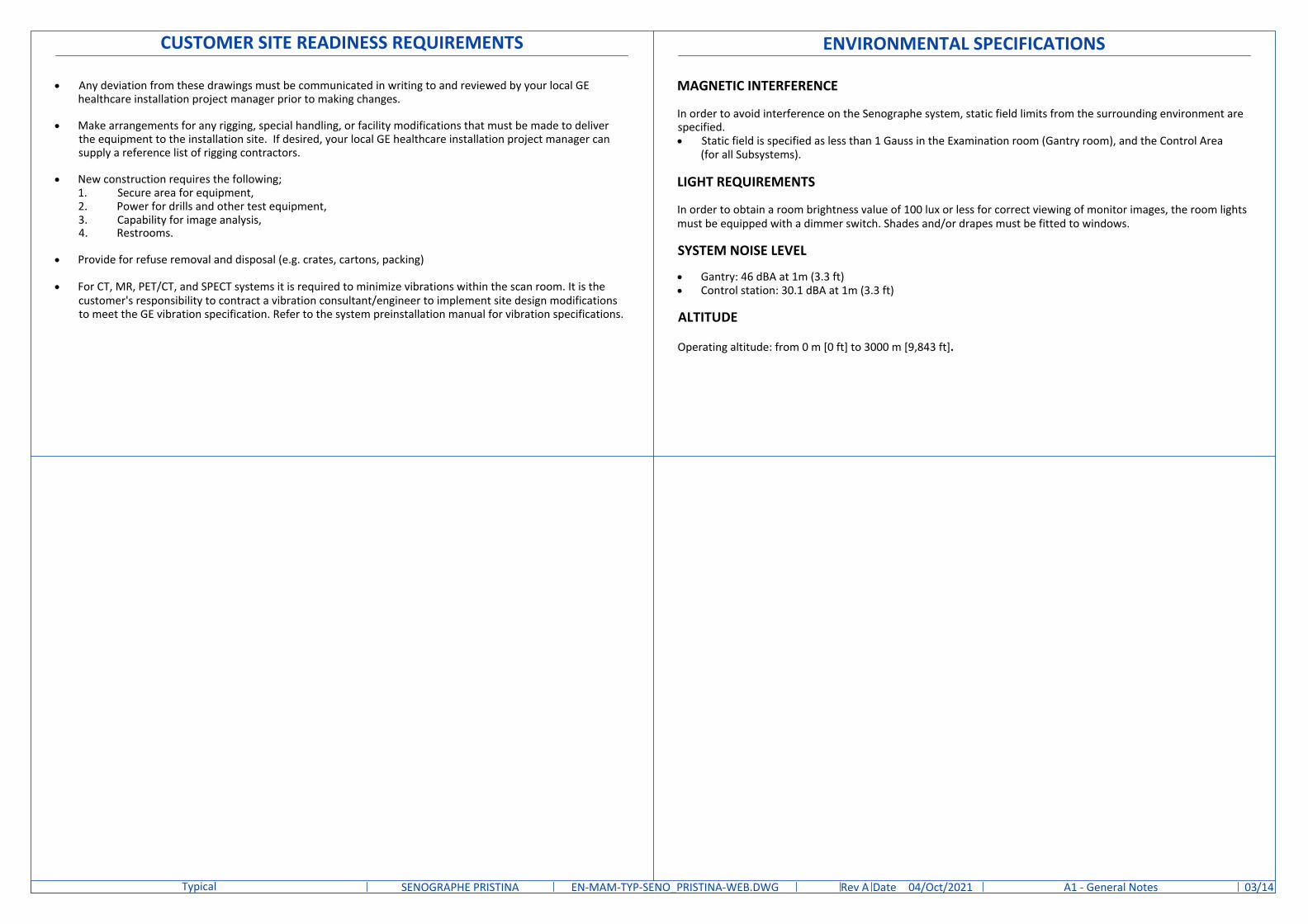
For Accessory Sales: (866) 281-7545 Options 1, 2, 1, 2 or mail to: [email protected]
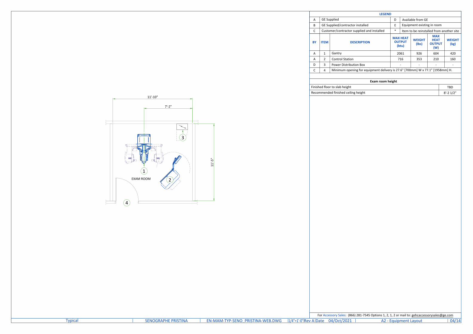
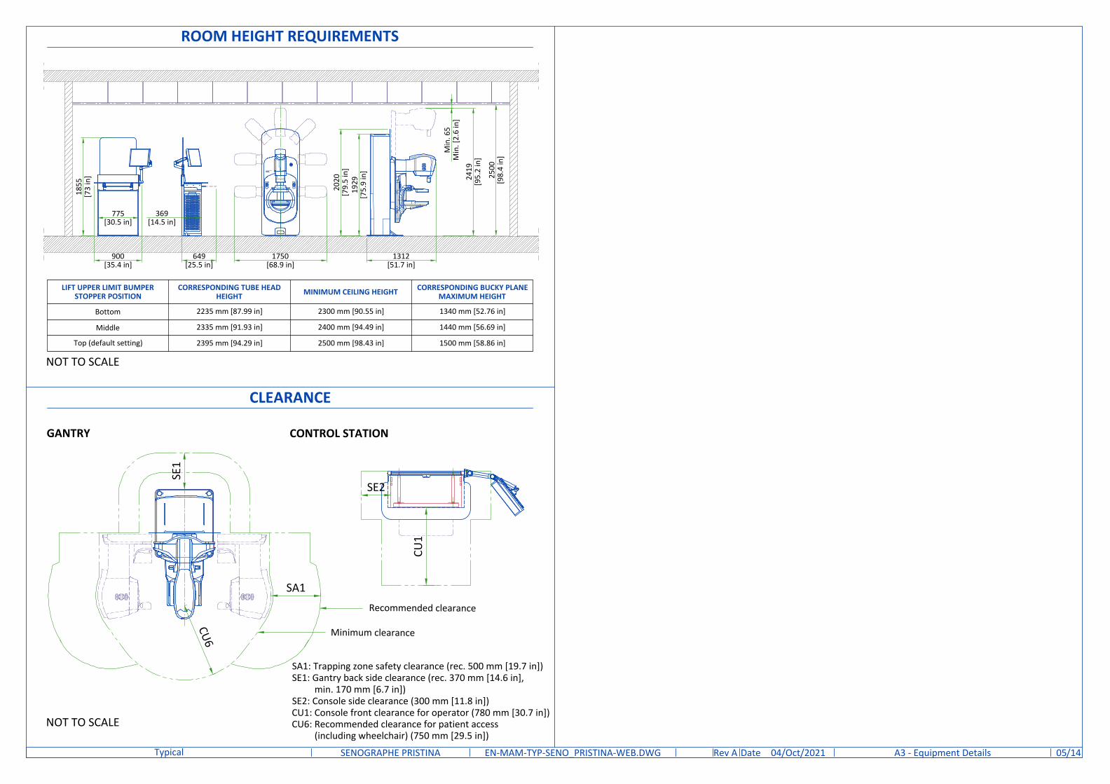
Exam room height
Finished floor to slab height
Recommended finished ceiling heightTBD
8'-2 1/2"
BY ITEM DESCRIPTIONMAX HEAT
OUTPUT(btu)
WEIGHT(lbs)
MAXHEAT
OUTPUT(W)
WEIGHT(kg)
A 1 Gantry 2061 926 604 420
A 2 Control Station 716 353 210 160
D 3 Power Distribution Box - - - -
C 4 Minimum opening for equipment delivery is 27.6" [700mm] W x 77.1" [1958mm] H.
DateRev /14EN-MAM-TYP-SENO_PRISTINA-WEB.DWG A 04/Oct/2021SENOGRAPHE PRISTINATypical A2 - Equipment Layout 041/4"=1'-0"
EXAM ROOM
11'-10"
7'-2"
11'-5
"
1
2
3
4
LEGEND
A GE Supplied D Available from GEB GE Supplied/contractor installed E Equipment existing in room
C Customer/contractor supplied and installed * Item to be reinstalled from another site
CLEARANCE
GANTRY CONTROL STATION
NOT TO SCALE
SA1: Trapping zone safety clearance (rec. 500 mm [19.7 in])SE1: Gantry back side clearance (rec. 370 mm [14.6 in],
min. 170 mm [6.7 in])SE2: Console side clearance (300 mm [11.8 in])CU1: Console front clearance for operator (780 mm [30.7 in])CU6: Recommended clearance for patient access
Bottom 2235 mm [87.99 in] 2300 mm [90.55 in] 1340 mm [52.76 in]
Middle 2335 mm [91.93 in] 2400 mm [94.49 in] 1440 mm [56.69 in]
Top (default setting) 2395 mm [94.29 in] 2500 mm [98.43 in] 1500 mm [58.86 in]
NOT TO SCALE
1312[51.7 in]
649[25.5 in]
1750[68.9 in]
1855
[73
in]
900[35.4 in]
775[30.5 in]
369[14.5 in]
Pristina
Senographe
1929
[75.
9 in
]
2020
[79.
5 in
]
2419
[95.
2 in
]
Min
. 65
Min
. [2.
6 in
]
2500
[98.
4 in
]
DateRev /14EN-MAM-TYP-SENO_PRISTINA-WEB.DWG A 04/Oct/2021SENOGRAPHE PRISTINATypical A3 - Equipment Details 05
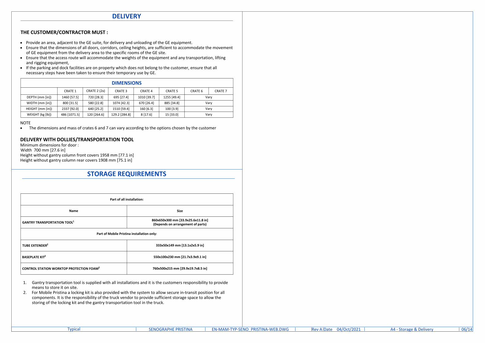
STORAGE REQUIREMENTS
Part of all installation:
Name Size
GANTRY TRANSPORTATION TOOL1 860x650x300 mm [33.9x25.6x11.8 in](Depends on arrangement of parts)
Part of Mobile Pristina installation only:
TUBE EXTENDER2 333x50x149 mm [13.1x2x5.9 in]
BASEPLATE KIT2 550x100x230 mm [21.7x3.9x9.1 in]
CONTROL STATION WORKTOP PROTECTION FOAM2 760x500x215 mm [29.9x19.7x8.5 in]
1. Gantry transportation tool is supplied with all installations and it is the customers responsibility to providemeans to store it on site.
2. For Mobile Pristina a locking kit is also provided with the system to allow secure in-transit position for allcomponents. It is the responsibility of the truck vendor to provide sufficient storage space to allow thestoring of the locking kit and the gantry transportation tool in the truck.
DELIVERY WITH DOLLIES/TRANSPORTATION TOOLMinimum dimensions for door :Width 700 mm [27.6 in]Height without gantry column front covers 1958 mm [77.1 in]Height without gantry column rear covers 1908 mm [75.1 in]
THE CUSTOMER/CONTRACTOR MUST :
· Provide an area, adjacent to the GE suite, for delivery and unloading of the GE equipment.· Ensure that the dimensions of all doors, corridors, ceiling heights, are sufficient to accommodate the movement
of GE equipment from the delivery area to the specific rooms of the GE site.· Ensure that the access route will accommodate the weights of the equipment and any transportation, lifting
and rigging equipment,· If the parking and dock facilities are on property which does not belong to the customer, ensure that all
necessary steps have been taken to ensure their temporary use by GE.
NOTE· The dimensions and mass of crates 6 and 7 can vary according to the options chosen by the customer
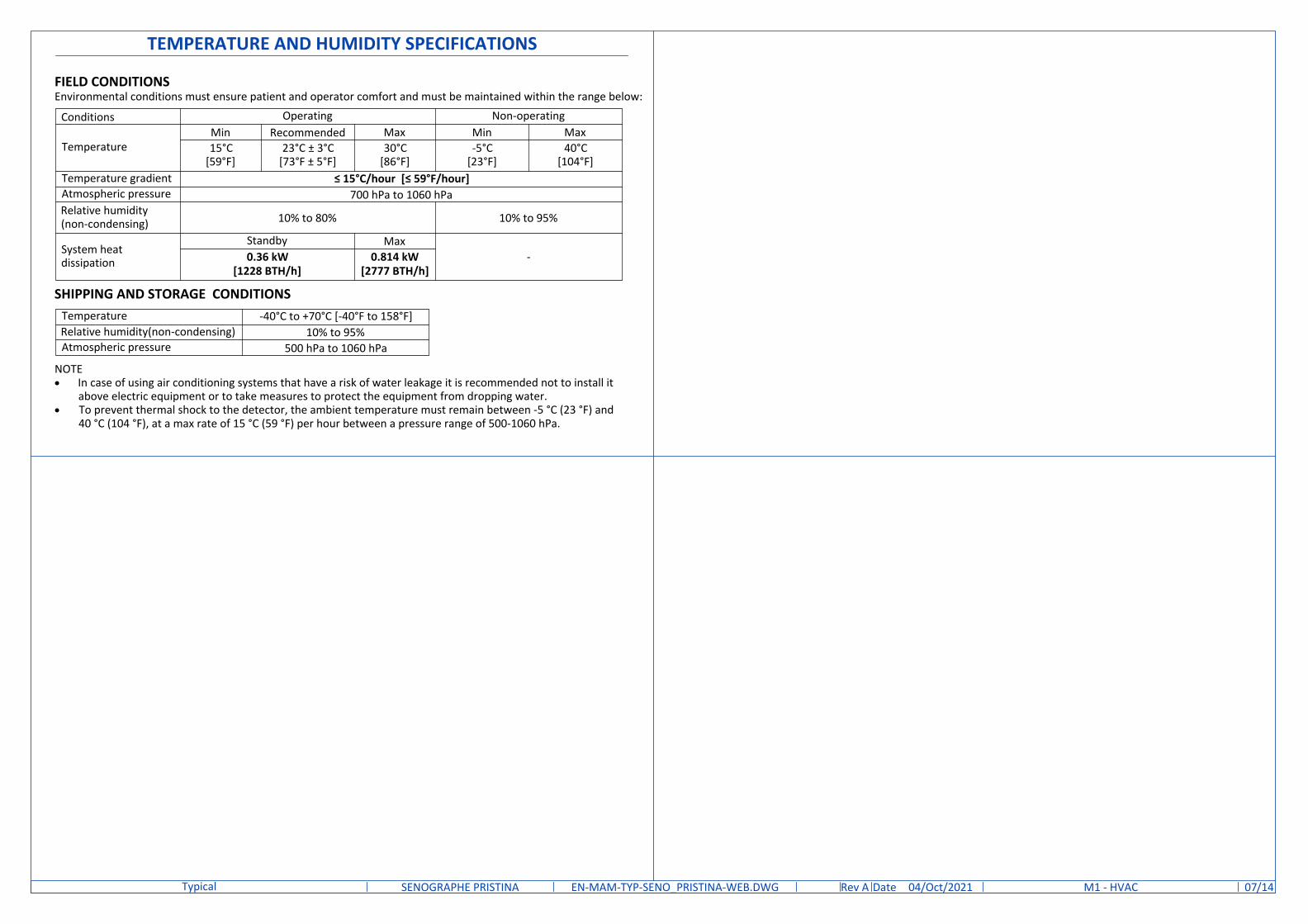
FIELD CONDITIONSEnvironmental conditions must ensure patient and operator comfort and must be maintained within the range below:
Conditions Operating Non-operating
TemperatureMin Recommended Max Min Max15°C
[59°F]23°C ± 3°C
[73°F ± 5°F]30°C
[86°F]-5°C
[23°F]40°C
[104°F]Temperature gradient ≤ 15°C/hour [≤ 59°F/hour]Atmospheric pressure 700 hPa to 1060 hPaRelative humidity(non-condensing) 10% to 80% 10% to 95%
System heatdissipation
Standby Max-0.36 kW
[1228 BTH/h]0.814 kW
[2777 BTH/h]
Temperature -40°C to +70°C [-40°F to 158°F]Relative humidity(non-condensing) 10% to 95%Atmospheric pressure 500 hPa to 1060 hPa
NOTE· In case of using air conditioning systems that have a risk of water leakage it is recommended not to install it
above electric equipment or to take measures to protect the equipment from dropping water.· To prevent thermal shock to the detector, the ambient temperature must remain between -5 °C (23 °F) and
40 °C (104 °F), at a max rate of 15 °C (59 °F) per hour between a pressure range of 500-1060 hPa.
DateRev /14EN-MAM-TYP-SENO_PRISTINA-WEB.DWG A 04/Oct/2021SENOGRAPHE PRISTINATypical M1 - HVAC 07
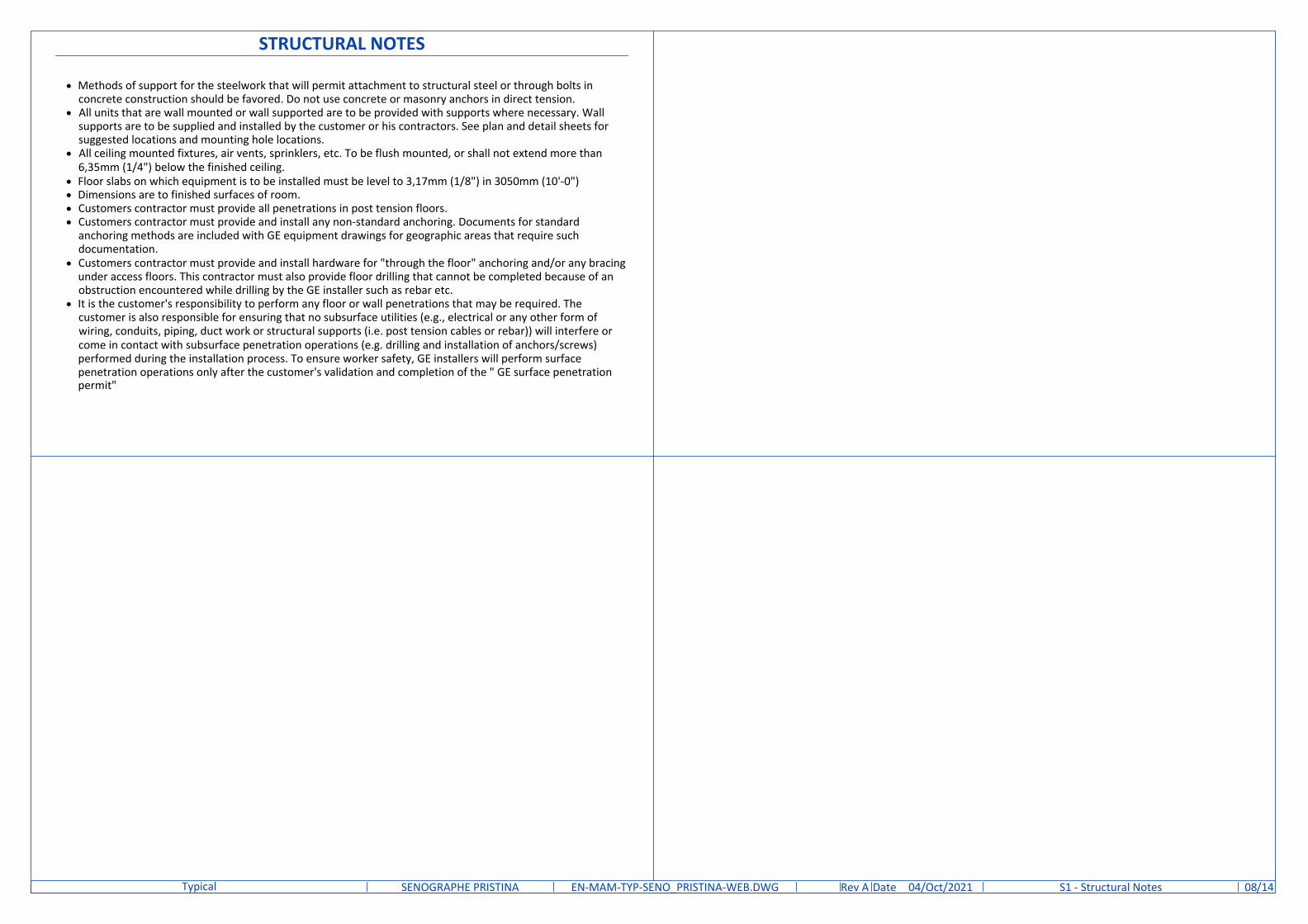
STRUCTURAL NOTES
· Methods of support for the steelwork that will permit attachment to structural steel or through bolts inconcrete construction should be favored. Do not use concrete or masonry anchors in direct tension.
· All units that are wall mounted or wall supported are to be provided with supports where necessary. Wallsupports are to be supplied and installed by the customer or his contractors. See plan and detail sheets forsuggested locations and mounting hole locations.
· All ceiling mounted fixtures, air vents, sprinklers, etc. To be flush mounted, or shall not extend more than6,35mm (1/4") below the finished ceiling.
· Floor slabs on which equipment is to be installed must be level to 3,17mm (1/8") in 3050mm (10'-0")· Dimensions are to finished surfaces of room.· Customers contractor must provide all penetrations in post tension floors.· Customers contractor must provide and install any non-standard anchoring. Documents for standard
anchoring methods are included with GE equipment drawings for geographic areas that require suchdocumentation.
· Customers contractor must provide and install hardware for "through the floor" anchoring and/or any bracingunder access floors. This contractor must also provide floor drilling that cannot be completed because of anobstruction encountered while drilling by the GE installer such as rebar etc.
· It is the customer's responsibility to perform any floor or wall penetrations that may be required. Thecustomer is also responsible for ensuring that no subsurface utilities (e.g., electrical or any other form ofwiring, conduits, piping, duct work or structural supports (i.e. post tension cables or rebar)) will interfere orcome in contact with subsurface penetration operations (e.g. drilling and installation of anchors/screws)performed during the installation process. To ensure worker safety, GE installers will perform surfacepenetration operations only after the customer's validation and completion of the " GE surface penetrationpermit"
DateRev /14EN-MAM-TYP-SENO_PRISTINA-WEB.DWG A 04/Oct/2021SENOGRAPHE PRISTINATypical S1 - Structural Notes 08
DateRev /14EN-MAM-TYP-SENO_PRISTINA-WEB.DWG A 04/Oct/2021SENOGRAPHE PRISTINATypical S2 - Structural Layout 091/4"=1'-0"
7'-2"
8'-0"
6'-5"
1'-8
"
1
EXAM ROOM2
4'-6"
4'-4
"
3'-3"
3'-1
"
1'-6"
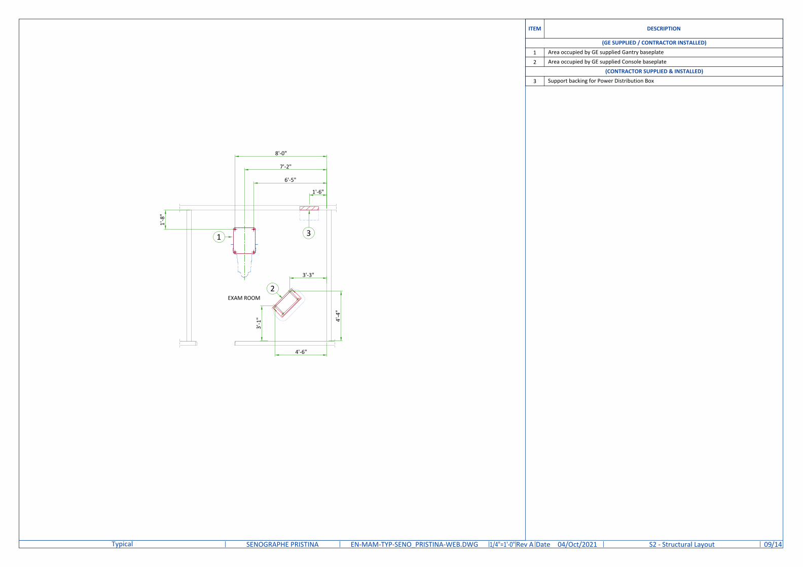
ITEM DESCRIPTION
(GE SUPPLIED / CONTRACTOR INSTALLED)
1 Area occupied by GE supplied Gantry baseplate
2 Area occupied by GE supplied Console baseplate
(CONTRACTOR SUPPLIED & INSTALLED)
3 Support backing for Power Distribution Box
3
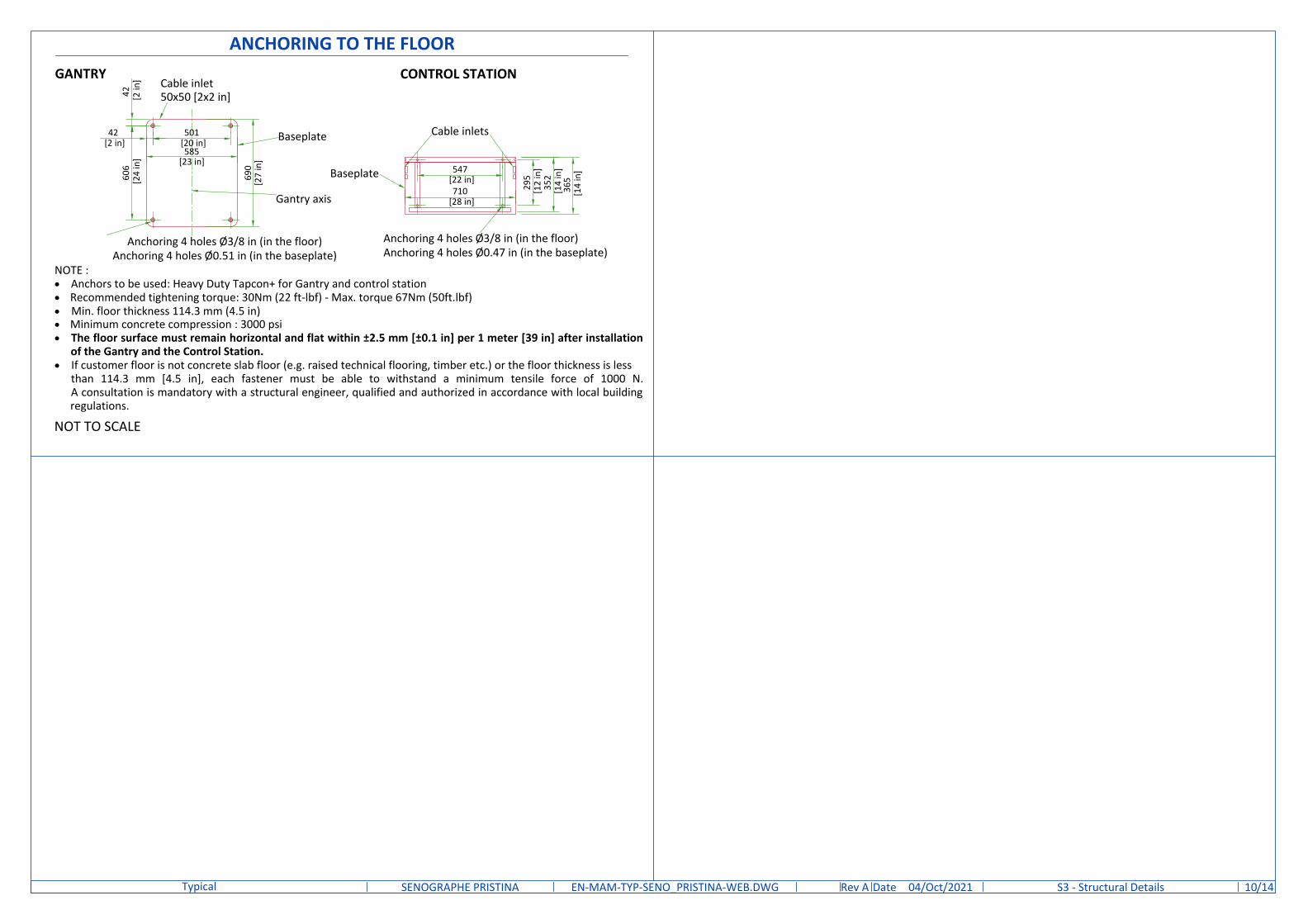
ANCHORING TO THE FLOOR
NOT TO SCALE
GANTRY CONTROL STATION
Baseplate
Cable inlets
295
[12
in]
710 [28 in]
365
[14
in]
Gantry axis
Baseplate
Cable inlet50x50 [2x2 in]
606
[24
in]
585[23 in]
501 [20 in]
42 [2 in
]
690
[27
in]
42 [2 in]
352
[14
in]547
[22 in]
Anchoring 4 holes Ø3/8 in (in the floor) Anchoring 4 holes Ø0.51 in (in the baseplate)
Anchoring 4 holes Ø3/8 in (in the floor) Anchoring 4 holes Ø0.47 in (in the baseplate)
NOTE :· Anchors to be used: Heavy Duty Tapcon+ for Gantry and control station· Recommended tightening torque: 30Nm (22 ft-lbf) - Max. torque 67Nm (50ft.lbf)· Min. floor thickness 114.3 mm (4.5 in)· Minimum concrete compression : 3000 psi· The floor surface must remain horizontal and flat within ±2.5 mm [±0.1 in] per 1 meter [39 in] after installation
of the Gantry and the Control Station.· If customer floor is not concrete slab floor (e.g. raised technical flooring, timber etc.) or the floor thickness is less
than 114.3 mm [4.5 in], each fastener must be able to withstand a minimum tensile force of 1000 N.A consultation is mandatory with a structural engineer, qualified and authorized in accordance with local buildingregulations.
DateRev /14EN-MAM-TYP-SENO_PRISTINA-WEB.DWG A 04/Oct/2021SENOGRAPHE PRISTINATypical S3 - Structural Details 10
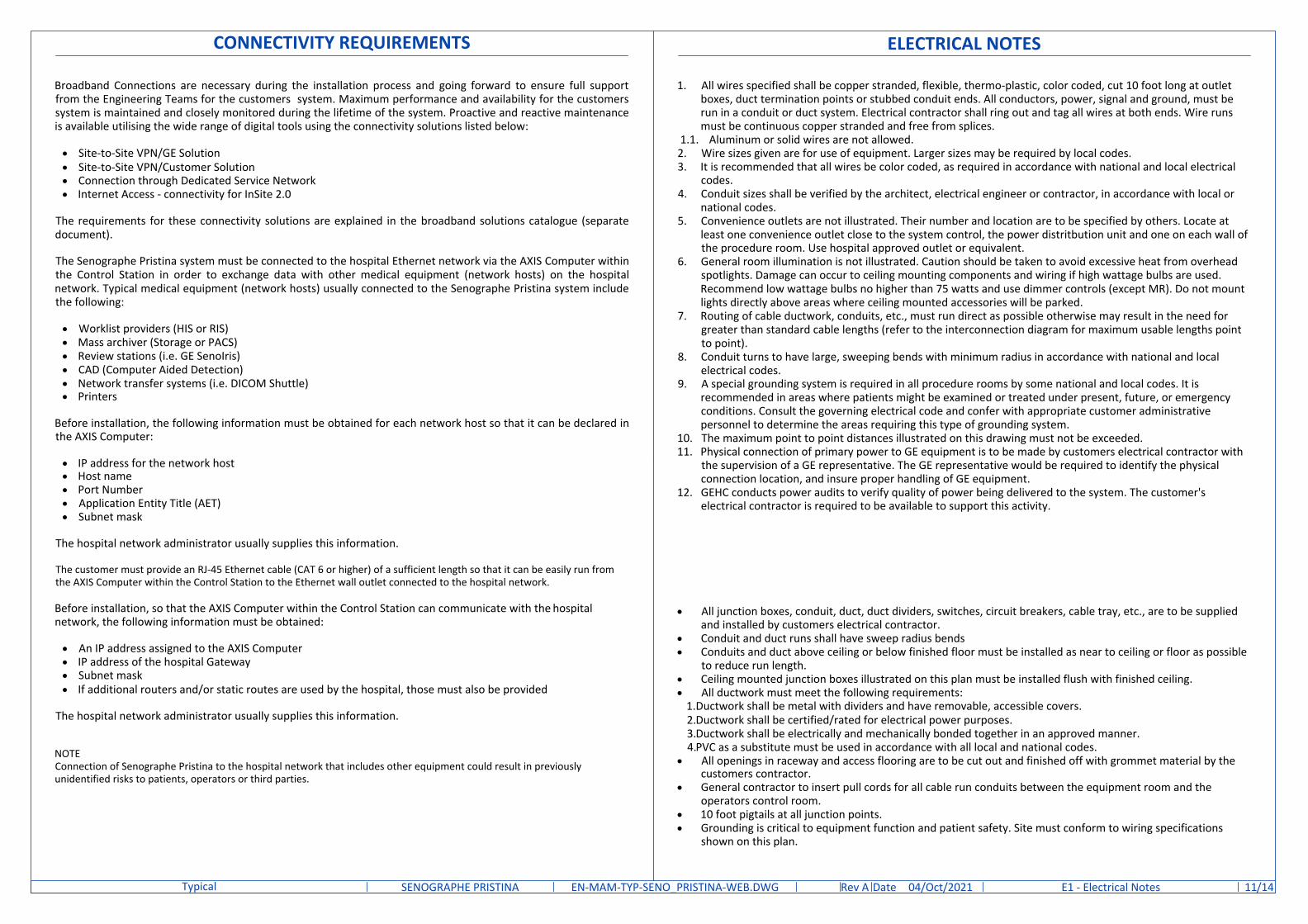
CONNECTIVITY REQUIREMENTS
Broadband Connections are necessary during the installation process and going forward to ensure full supportfrom the Engineering Teams for the customers system. Maximum performance and availability for the customerssystem is maintained and closely monitored during the lifetime of the system. Proactive and reactive maintenanceis available utilising the wide range of digital tools using the connectivity solutions listed below:
· Site-to-Site VPN/GE Solution· Site-to-Site VPN/Customer Solution· Connection through Dedicated Service Network· Internet Access - connectivity for InSite 2.0
The requirements for these connectivity solutions are explained in the broadband solutions catalogue (separatedocument).
The Senographe Pristina system must be connected to the hospital Ethernet network via the AXIS Computer withinthe Control Station in order to exchange data with other medical equipment (network hosts) on the hospitalnetwork. Typical medical equipment (network hosts) usually connected to the Senographe Pristina system includethe following:
· Worklist providers (HIS or RIS)· Mass archiver (Storage or PACS)· Review stations (i.e. GE SenoIris)· CAD (Computer Aided Detection)· Network transfer systems (i.e. DICOM Shuttle)· Printers
Before installation, the following information must be obtained for each network host so that it can be declared inthe AXIS Computer:
· IP address for the network host· Host name· Port Number· Application Entity Title (AET)· Subnet mask
The hospital network administrator usually supplies this information.
The customer must provide an RJ-45 Ethernet cable (CAT 6 or higher) of a sufficient length so that it can be easily run fromthe AXIS Computer within the Control Station to the Ethernet wall outlet connected to the hospital network.
Before installation, so that the AXIS Computer within the Control Station can communicate with the hospitalnetwork, the following information must be obtained:
· An IP address assigned to the AXIS Computer· IP address of the hospital Gateway· Subnet mask· If additional routers and/or static routes are used by the hospital, those must also be provided
The hospital network administrator usually supplies this information.
NOTEConnection of Senographe Pristina to the hospital network that includes other equipment could result in previouslyunidentified risks to patients, operators or third parties.
ELECTRICAL NOTES
· All junction boxes, conduit, duct, duct dividers, switches, circuit breakers, cable tray, etc., are to be suppliedand installed by customers electrical contractor.
· Conduit and duct runs shall have sweep radius bends· Conduits and duct above ceiling or below finished floor must be installed as near to ceiling or floor as possible
to reduce run length.· Ceiling mounted junction boxes illustrated on this plan must be installed flush with finished ceiling.· All ductwork must meet the following requirements:
1.Ductwork shall be metal with dividers and have removable, accessible covers.2.Ductwork shall be certified/rated for electrical power purposes.3.Ductwork shall be electrically and mechanically bonded together in an approved manner.4.PVC as a substitute must be used in accordance with all local and national codes.
· All openings in raceway and access flooring are to be cut out and finished off with grommet material by thecustomers contractor.
· General contractor to insert pull cords for all cable run conduits between the equipment room and theoperators control room.
· 10 foot pigtails at all junction points.· Grounding is critical to equipment function and patient safety. Site must conform to wiring specifications
shown on this plan.
1. All wires specified shall be copper stranded, flexible, thermo-plastic, color coded, cut 10 foot long at outletboxes, duct termination points or stubbed conduit ends. All conductors, power, signal and ground, must berun in a conduit or duct system. Electrical contractor shall ring out and tag all wires at both ends. Wire runsmust be continuous copper stranded and free from splices.
1.1. Aluminum or solid wires are not allowed.2. Wire sizes given are for use of equipment. Larger sizes may be required by local codes.3. It is recommended that all wires be color coded, as required in accordance with national and local electrical
codes.4. Conduit sizes shall be verified by the architect, electrical engineer or contractor, in accordance with local or
national codes.5. Convenience outlets are not illustrated. Their number and location are to be specified by others. Locate at
least one convenience outlet close to the system control, the power distritbution unit and one on each wall ofthe procedure room. Use hospital approved outlet or equivalent.
6. General room illumination is not illustrated. Caution should be taken to avoid excessive heat from overheadspotlights. Damage can occur to ceiling mounting components and wiring if high wattage bulbs are used.Recommend low wattage bulbs no higher than 75 watts and use dimmer controls (except MR). Do not mountlights directly above areas where ceiling mounted accessories will be parked.
7. Routing of cable ductwork, conduits, etc., must run direct as possible otherwise may result in the need forgreater than standard cable lengths (refer to the interconnection diagram for maximum usable lengths pointto point).
8. Conduit turns to have large, sweeping bends with minimum radius in accordance with national and localelectrical codes.
9. A special grounding system is required in all procedure rooms by some national and local codes. It isrecommended in areas where patients might be examined or treated under present, future, or emergencyconditions. Consult the governing electrical code and confer with appropriate customer administrativepersonnel to determine the areas requiring this type of grounding system.
10. The maximum point to point distances illustrated on this drawing must not be exceeded.11. Physical connection of primary power to GE equipment is to be made by customers electrical contractor with
the supervision of a GE representative. The GE representative would be required to identify the physicalconnection location, and insure proper handling of GE equipment.
12. GEHC conducts power audits to verify quality of power being delivered to the system. The customer'selectrical contractor is required to be available to support this activity.
DateRev /14EN-MAM-TYP-SENO_PRISTINA-WEB.DWG A 04/Oct/2021SENOGRAPHE PRISTINATypical E1 - Electrical Notes 11
AB
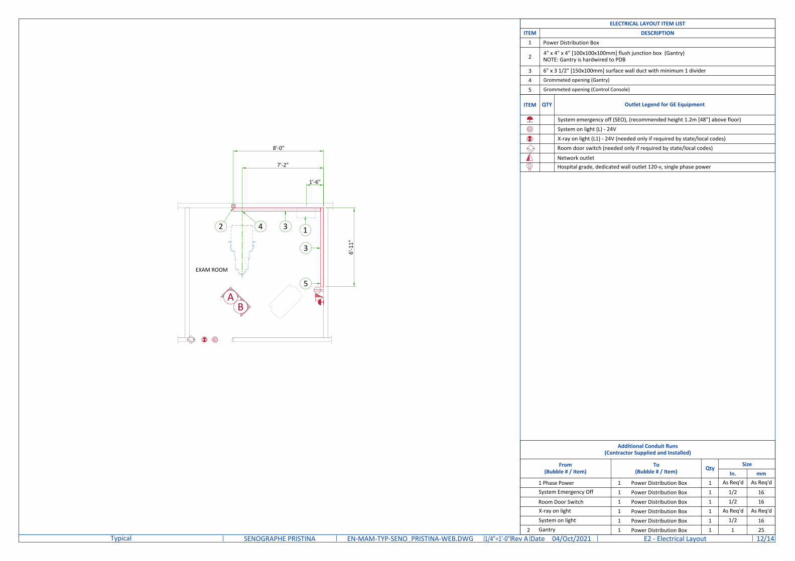
ITEM QTY Outlet Legend for GE Equipment
System emergency off (SEO), (recommended height 1.2m [48"] above floor)
System on light (L) - 24V
X-ray on light (L1) - 24V (needed only if required by state/local codes)
Room door switch (needed only if required by state/local codes)
Network outletHospital grade, dedicated wall outlet 120-v, single phase power
DateRev /14EN-MAM-TYP-SENO_PRISTINA-WEB.DWG A 04/Oct/2021SENOGRAPHE PRISTINATypical E2 - Electrical Layout 121/4"=1'-0"
EXAM ROOM
7'-2"
8'-0"
1'-6"
6'-1
1"
13
3
2
Additional Conduit Runs(Contractor Supplied and Installed)
From(Bubble # / Item)
To(Bubble # / Item) Qty
SizeIn. mm
1 Phase Power 1 Power Distribution Box 1 As Req'd As Req'd
System Emergency Off 1 Power Distribution Box 1 1/2 16
Room Door Switch 1 Power Distribution Box 1 1/2 16X-ray on light 1 Power Distribution Box 1 As Req'd As Req'd
System on light 1 Power Distribution Box 1 1/2 16
2 Gantry 1 Power Distribution Box 1 1 25
ELECTRICAL LAYOUT ITEM LIST
ITEM DESCRIPTION
1 Power Distribution Box
2 4" x 4" x 4" [100x100x100mm] flush junction box (Gantry)NOTE: Gantry is hardwired to PDB
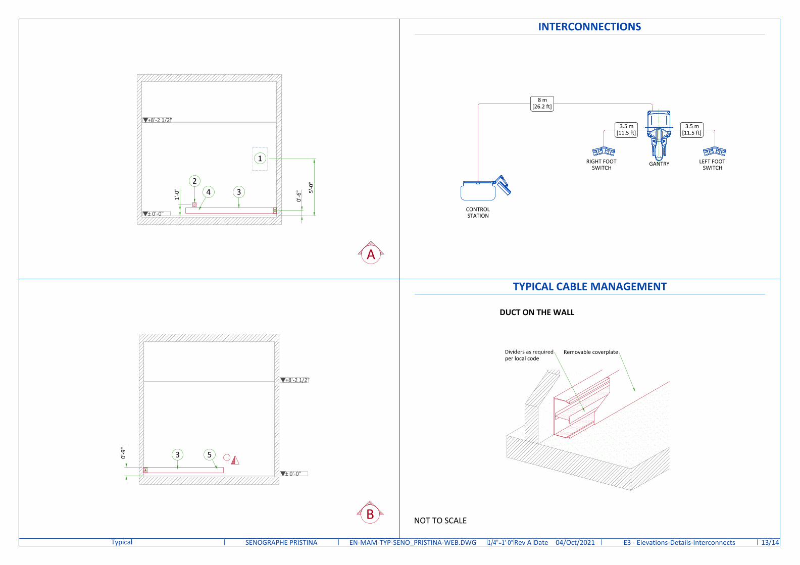
3 6" x 3 1/2" [150x100mm] surface wall duct with minimum 1 divider
4 Grommeted opening (Gantry)
5 Grommeted opening (Control Console)
4
5
B
A
TYPICAL CABLE MANAGEMENT
Removable coverplate
DUCT ON THE WALL
Dividers as requiredper local code
NOT TO SCALE
INTERCONNECTIONS
CONTROLSTATION
GANTRYRIGHT FOOTSWITCH
8 m[26.2 ft]
3.5 m[11.5 ft]
LEFT FOOTSWITCH
3.5 m[11.5 ft]
DateRev /14EN-MAM-TYP-SENO_PRISTINA-WEB.DWG A 04/Oct/2021SENOGRAPHE PRISTINATypical E3 - Elevations-Details-Interconnects 131/4"=1'-0"
+8'-2 1/2"
1
3
± 0'-0"
0'-6
" 5'-0
"
0'-9
"
3
+8'-2 1/2"
± 0'-0"
1'-0
"2
4
5
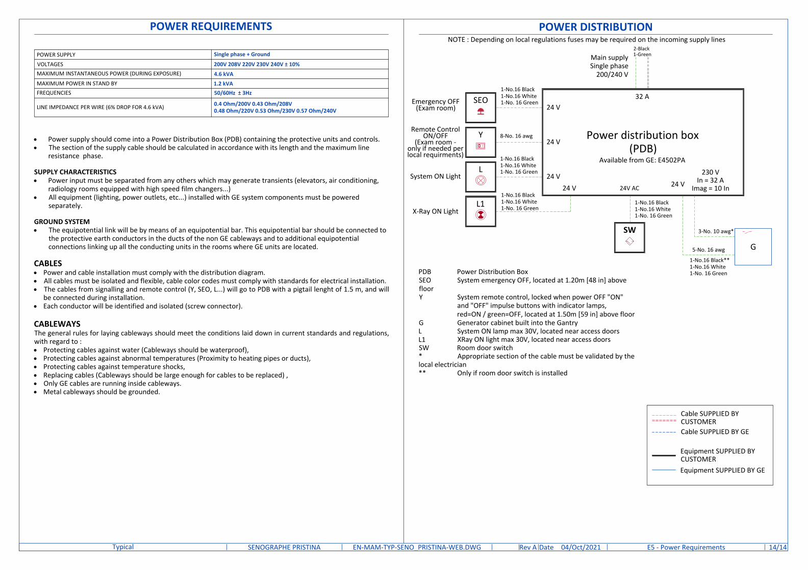
POWER REQUIREMENTS
· Power supply should come into a Power Distribution Box (PDB) containing the protective units and controls.· The section of the supply cable should be calculated in accordance with its length and the maximum line
resistance phase.
SUPPLY CHARACTERISTICS· Power input must be separated from any others which may generate transients (elevators, air conditioning,
radiology rooms equipped with high speed film changers...)· All equipment (lighting, power outlets, etc...) installed with GE system components must be powered
separately.
GROUND SYSTEM· The equipotential link will be by means of an equipotential bar. This equipotential bar should be connected to
the protective earth conductors in the ducts of the non GE cableways and to additional equipotentialconnections linking up all the conducting units in the rooms where GE units are located.
CABLES· Power and cable installation must comply with the distribution diagram.· All cables must be isolated and flexible, cable color codes must comply with standards for electrical installation.· The cables from signalling and remote control (Y, SEO, L...) will go to PDB with a pigtail lenght of 1.5 m, and will
be connected during installation.· Each conductor will be identified and isolated (screw connector).
CABLEWAYSThe general rules for laying cableways should meet the conditions laid down in current standards and regulations,with regard to :· Protecting cables against water (Cableways should be waterproof),· Protecting cables against abnormal temperatures (Proximity to heating pipes or ducts),· Protecting cables against temperature shocks,· Replacing cables (Cableways should be large enough for cables to be replaced) ,· Only GE cables are running inside cableways.· Metal cableways should be grounded.
POWER SUPPLY Single phase + Ground
VOLTAGES 200V 208V 220V 230V 240V ± 10%MAXIMUM INSTANTANEOUS POWER (DURING EXPOSURE) 4.6 kVAMAXIMUM POWER IN STAND BY 1.2 kVAFREQUENCIES 50/60Hz ± 3Hz
LINE IMPEDANCE PER WIRE (6% DROP FOR 4.6 kVA) 0.4 Ohm/200V 0.43 Ohm/208V0.48 Ohm/220V 0.53 Ohm/230V 0.57 Ohm/240V
24 V
24 V
SEO24 V
24 V
Power distribution box(PDB)
Main supplySingle phase
200/240 V
Emergency OFF(Exam room)
24 V
POWER DISTRIBUTION
32 A
230 VIn = 32 A
Imag = 10 In
L
Y
L1
Remote ControlON/OFF
(Exam room -only if needed perlocal requirments)
X-Ray ON Light
System ON Light
NOTE : Depending on local regulations fuses may be required on the incoming supply lines
8-No. 16 awg
1-No.16 Black1-No.16 White1-No. 16 Green
2-Black1-Green
1-No.16 Black1-No.16 White1-No. 16 Green
1-No.16 Black1-No.16 White1-No. 16 Green
1-No.16 Black1-No.16 White1-No. 16 Green
1-No.16 Black**1-No.16 White1-No. 16 Green
3-No. 10 awg*
5-No. 16 awg
SW
24V AC
PDB Power Distribution BoxSEO System emergency OFF, located at 1.20m [48 in] abovefloorY System remote control, locked when power OFF "ON"
and "OFF" impulse buttons with indicator lamps,red=ON / green=OFF, located at 1.50m [59 in] above floor
G Generator cabinet built into the GantryL System ON lamp max 30V, located near access doorsL1 XRay ON light max 30V, located near access doorsSW Room door switch* Appropriate section of the cable must be validated by thelocal electrician** Only if room door switch is installed
Cable SUPPLIED BYCUSTOMER
Equipment SUPPLIED BY GE
Equipment SUPPLIED BYCUSTOMER
Cable SUPPLIED BY GE
G
Available from GE: E4502PA
DateRev /14EN-MAM-TYP-SENO_PRISTINA-WEB.DWG A 04/Oct/2021SENOGRAPHE PRISTINATypical E5 - Power Requirements 14