Instruction Sheet Hazardous voltage. Will cause death, serious injury, or property damage. Turn off power before working on this equipment. Horizontal Bus Bar Splice E87010-A0242-T002-A5-MCC 1200A and 1600 Bus Systems Double Bar Assembly March, 2013 Each contains: Horizontal bus bar splice installation instructions for: Procedure A - (See Note 1) 1. Align and mechanically fasten the two shipping splits or sections together. For access to the rear of the horizontal bus bars, remove the upper rear panels on the two adjacent sections that are to be spliced together. If access from the rear is not possible, remove the top cover panels instead. 2. The horizontal bus bar splices should be installed in the following order: L3, L2 and L1. 1600A Splice Kits ( ³/8 “ x 2” Copper Bus Bar) 1200A Splice Kits ( ¹/4 “ x 2” Copper Bus Bar) 6 Bus Bar Splices (tin plated) or 6 Bus Bar Splices (silver plated) 6 Bus Bar Clamps 4 ³/8 Belleville Washers 12 ³/8 -16 Hex Nuts with Conical Washer 2 Adapters 4 ³/8 -16 x 2 Hex Head Bolts Notes: 1. When the horizontal bus bars are accessible from the rear or from the top of the motor control center by removing the rear or top panels, use Procedure A. 2. When the horizontal bus bars are accessible only from the front of the motor control center, use Procedure B. 3. The two adapters and four hex head kits supplied with the kits are required for Procedure B only. 1200A Splice Kits (³/8 “ x 2” Aluminum Bus Bar) Contains: 6 Bus Bar Splices (tin plated) 6 Bus Bar Clamps 4 Belleville Washers 12 ³/8 -16 Hex Nuts with Conical Washer 2 Adapters 4 ³/8 -16 x 2 Hex Head Bolts Loose electrical connections can cause death, serious injury or property damage. Tighten splice connections and any connections loosened to install the splice to 20 lb.-ft. minimum. 3. Refer to Figure 1. Loosen the horizontal and vertical bus bar mounting hardware indicated by X’s. Loosen nuts as far as possible without removing them. 4. Refer to Figure 2. Separate front and rear horizontal bus bars and insert rear bus bar splice for: L3 from the top L2 from the top L1 from the top 5. Refer to Figure 3. Install front bus bar splice for L3, using hardware shown. Repeat for L2 and L1. 6. Tighten all mounting hardware to 20 lb.-ft. 7. Replace panels removed in Step 1. Figure 1: Front view of MCC showing bus system A5E31944957A
Transcript
Instruction SheetHazardous voltage.Will cause death, serious injury, or property damage.
Turn off power before working on this equipment.
Horizontal Bus Bar SpliceE87010-A0242-T002-A5-MCC
1200A and 1600 Bus SystemsDouble Bar Assembly
March, 2013
Each contains:
Horizontal bus bar splice installation instructions for:
Procedure A - (See Note 1)1. Align and mechanically fasten the two shipping
splits or sections together. For access to the rear of the horizontal bus bars, remove the upper rear panels on the two adjacent sections that are to be spliced together. If access from the rear is not possible, remove the top cover panels instead.
2. The horizontal bus bar splices should be installed in the following order: L3, L2 and L1.
1600A Splice Kits ( ³⁄8 “ x 2” Copper Bus Bar)1200A Splice Kits ( ¹ ⁄4 “ x 2” Copper Bus Bar)
6 Bus Bar Splices (tin plated)or 6 Bus Bar Splices (silver plated)6 Bus Bar Clamps4 ³⁄8 Belleville Washers12 ³⁄8 -16 Hex Nuts with Conical Washer2 Adapters4 ³⁄8 -16 x 2 Hex Head Bolts
Notes:1. When the horizontal bus bars are accessible from the
rear or from the top of the motor control center by removing the rear or top panels, use Procedure A.
2. When the horizontal bus bars are accessible only from the front of the motor control center, use Procedure B.
3. The two adapters and four hex head kits supplied with the kits are required for Procedure B only.
1200A Splice Kits (³⁄8 “ x 2” Aluminum Bus Bar)
Contains:6 Bus Bar Splices (tin plated)6 Bus Bar Clamps4 Belleville Washers12 ³⁄8 -16 Hex Nuts with Conical Washer2 Adapters4 ³⁄8 -16 x 2 Hex Head Bolts
Loose electrical connections can causedeath, serious injury or property damage.
Tighten splice connections and any connectionsloosened to install the splice to 20 lb.-ft. minimum.
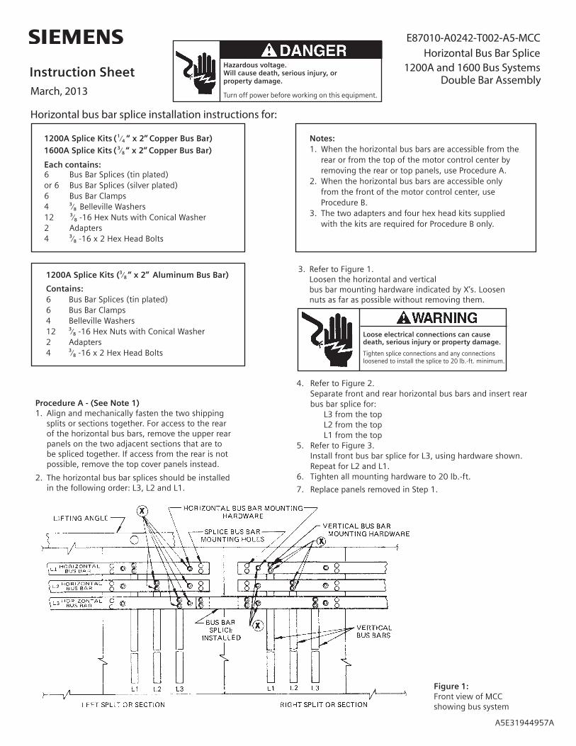
3. Refer to Figure 1. Loosen the horizontal and vertical bus bar mounting hardware indicated by X’s. Loosen nuts as far as possible without removing them.
4. Refer to Figure 2.Separate front and rear horizontal bus bars and insert rearbus bar splice for:
L3 from the topL2 from the topL1 from the top
5. Refer to Figure 3.Install front bus bar splice for L3, using hardware shown. Repeat for L2 and L1.
6. Tighten all mounting hardware to 20 lb.-ft.
7. Replace panels removed in Step 1.
Figure 1: Front view of MCC showing bus system
A5E31944957A
Siemens Industry, Inc. 5300 Triangle Parkway, Norcross, GA 30092 A5E31944957A
IMPORTANT
THESE INSTRUCTIONS DO NOT PURPORT TO COVER ALL DETAILS OR VARIATIONS IN EQUIPMENT, NOR TO PROVIDE FOR EVERY POSSIBLE CONTINGENCY TO BE MET IN CONNECTION WITH INSTALLATION, OPERATION OR MAINTENANCE. SHOULD FURTHER INFORMATION BE DESIRED OR SHOULD PARTICULAR PROBLEMS ARISE WHICH ARE NOT COVERED SUFFICIENTLY FOR THE PURCHASER’S PURPOSES, THE MATTER SHOULD BE REFERRED TO THE LOCAL SIEMENS SALES OFFICE.
THE CONTENTS OF THIS INSTRUCTION MANUAL SHALL NOT BECOME PART OF OR MODIFY ANY PRIOROR EXISTING AGREEMENT, COMMITMENT OR RELATIONSHIP. THE SALES CONTRACT CONTAINS THEENTIRE OBLIGATION OF SIEMENS. THE WARRANTY CONTAINED IN THE CONTRACT BETWEEN THEPARTIES IS THE SOLE WARRANTY OF SIEMENS. ANY STATEMENTS CONTAINED HEREIN DO NOT CREATE NEW WARRANTIES OR MODIFY THE EXISTING WARRANTY.
.eciton tuohtiw egnahc ot tcejbus era snoitacificepS
Procedure B - (see note 2)1. Align and mechanically fasten the two shipping splits or
sections together. Remove the top cover panels on the
If access from the rear is not possible, remove the top cover
2. The horizontal bus bar splices should be installed in the following order: L3, L2, and L1.
3. Refer to Figure 1.Loosen the horizontal and vertical bus bar mounting hardware
indicated by X's. Loosen nuts as far as possible without removing them.
4. Refer to Figures 2 and 3 (For L3 only).Separate front and rear horizontal bus bars and insert rear bus bar splice L3 from the top. Install front bus bar splice using hardware shown in Figure 3.
5. Refer to Figures 2 and 4 (For L2 only).Separate front and rear horizontal bus bars and insert rear bus bar splice for L2 from the top. Insert bus bar clamps from the rear and install nuts on the lower studs so that the upper studs do not project beyond the front horizontal bus bar (See Figure 4). Do not install front bus bar splice at this time.
6. Refer to Figures 2, 5 and 6 (For L1 only).Insert splice bar adapter on both left and right sections between orange insulator and rear horizontal bus bar as shown in Figure 5. Separate front and rear horizontal bus bars and insert rear bus bar splice L1 from the bottom. Install front bus bar splice using hardware shown in Figure 6.
7. Complete the L2 splice at this time. Pull the bus bar clamps into place and install front bus bar splice to L2 using hardware shown in Figure 3.
8. Tighten all mounting hardware to 20 lb.-ft.
Loose electrical connections cancause death, serious injury or property damage.
Tighten splice connections and anyconnections loosened to install thesplice to 20 lb-ft minimum.
Figure 2 - Top view of bus bar splice assembly
Figure 3 - Top view of bus bar splice assembly
Figure 4 - Side view of rear bus bar splice at L2 splice connection
- Top view of L1 showing splice bar adapter
Figure 6 - Top view of bus bar assembly for L1
Figure 5
two adjacent sections that are to be spliced together.