24
For internal circulation of BSNL only . E2-E3 Electrical Technical Earthing
For internal circulation of BSNL only
.
E2-E3
Electrical Technical
Earthing
WELCOME
• This is a presentation for the E2-E3 Electrical
( Technical) Module for the Topic: Earthing
• Eligibility: Those who have got the Upgradation to
from E2 to E3.
• This presentation is last updated on 15-3-2011.
• You can also visit the Digital library of BSNL to see this
topic.
For internal circulation of BSNL only
AGENDA
Objectives of Earthing
Requirement of effective Earthing
Various types of Earthing used in telecom installations
For internal circulation of BSNL only
For internal circulation of BSNL only
Objectives of Earthing System
• Reduction of Crosstalk and Noise
• To afford convenience & reliability in the operate path of
the circuits involved in the switching apparatus of
telecom circuits.
• To use as return path for the conductor in some
telegraph and voice circuits.
• To Protect costly apparatus and persons against foreign
voltages and leakage currents from power wirings to the
metallic frame of the equipment.
For internal circulation of BSNL only
• To protect buildings and equipments from lighting strikes
• Earthing power supply systems is used to effect
reliability of power as it helps to provide stability of
voltage conditions preventing excess fluctuations and
providing a measure of protection against lighting.
• To divert stray RF energy from sensitive audio, video
control and computer equipments
Requirements for Effective Earthing
• The resistance to the earth must be within allowable limit
for the particular application
• The electrode buried in ground must be :
• Having good electrical conductivity to carry highest specified
load current
• Immune to the corrosive action of the soil all along the period
• Of sufficient mechanical strength to enable them to be installed
without any damage
• Inert i.e. must not be a source of galavanic corrosion current
within the system to be protected
For internal circulation of BSNL only
• The earth electrode must provide as much as area of
contact as possible with the soil to reduce the resistance
of the current path to the earth
• The resistance of the earth connection must remain
within the allowable specified limit throughout the
session
For internal circulation of BSNL only
Classes of Earthing System
• Service Earthing system
– Equipment earthing for switching , transmission ,measuring
equipments etc.
• Protective Earthing System
– Power system earth to provide protection against excessive
current.
– Lighting protective earth to provide protection against excessive
voltage.
For internal circulation of BSNL only
Separate Earths Vs Common Earth
• separate earthing system for different purposes at a
common location have generally proved to be
unsatisfactory
• On the other hand separate earths have in the past been
desirable for certain categories of service earth. This has
usually been done to eliminate noise from the
telecommunication circuits.
For internal circulation of BSNL only
Design Principles for Earthing
System
• Adequate current capacity (DC or AC as appropriate)
• Adequate mechanical strength to withstand the rigors of
service without fracturing.
• In the case of lighting protective earths adequate-surge-
current carrying ability.
For internal circulation of BSNL only
Types of Earthing System
• Installation of Ring Earth around new telecom
departmental building:
– A trench, 30 cms wide and normally 150 cms deep is dug. The
depth should be 1-1.5 mt. In case of rocky area the depth may
be 60-90 cms. GI strip of size 50 x 3 mm is laid in the trench.
The joints are properly wrapped and sealed by waterproof tape.
For internal circulation of BSNL only
• Earthing of antenna Towers mounted on top of building:
– for earthing of tower on top of a building, 50 x3 GI Strip down
lead should be bonded to any two opposite tower legs and
brought down along out side of the building and connected to
the ring earth.
For internal circulation of BSNL only
Earthing of Waveguides
• The wave guide for UHF/VHF which are aluminum and
that for micro wave system which are proper wave guide
are mounted on the tower and connected to antenna. All
such wave guide should be individually earthed at the
top and at bottom of the tower and at in – between
intervals by earthing kits as recommended by the
manufacture.
For internal circulation of BSNL only
Service Earths
• Service earth which carry current (e.g. teleprinter earths
which may carry 20- 25 mA) must be capable of
surviving the discharge of such current to ground for
their flowing through a steel earth electrode.
For internal circulation of BSNL only
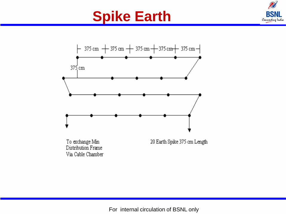
Spike Earth
• Spike electrodes consist of metal rods or pipes driven
vertically into the ground. Copper, stainless steel and
mild steel are the most suitable material being corrosion
resistant used as a rod electrodes.
• Figure:
For internal circulation of BSNL only
For internal circulation of BSNL only
Spike Earth
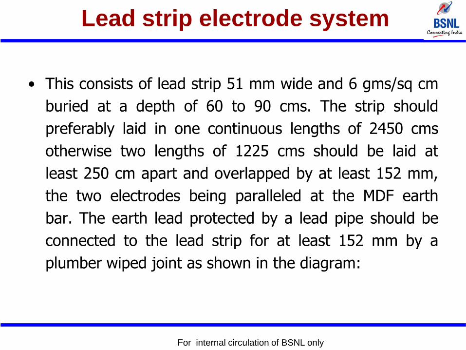
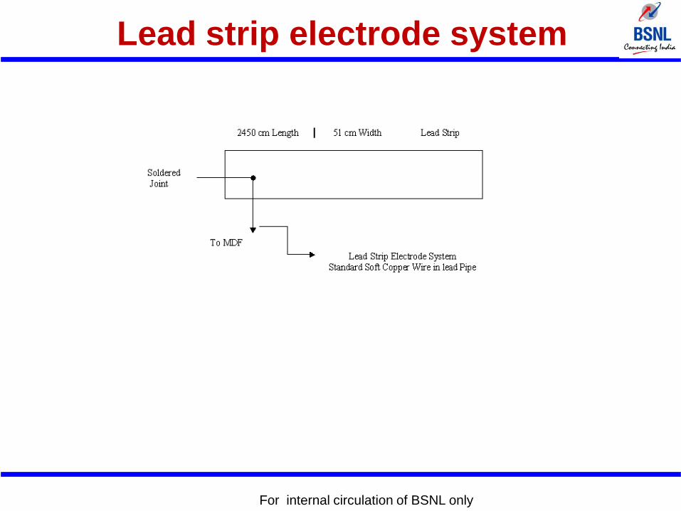
Lead strip electrode system
• This consists of lead strip 51 mm wide and 6 gms/sq cm
buried at a depth of 60 to 90 cms. The strip should
preferably laid in one continuous lengths of 2450 cms
otherwise two lengths of 1225 cms should be laid at
least 250 cm apart and overlapped by at least 152 mm,
the two electrodes being paralleled at the MDF earth
bar. The earth lead protected by a lead pipe should be
connected to the lead strip for at least 152 mm by a
plumber wiped joint as shown in the diagram:
For internal circulation of BSNL only
For internal circulation of BSNL only
Lead strip electrode system
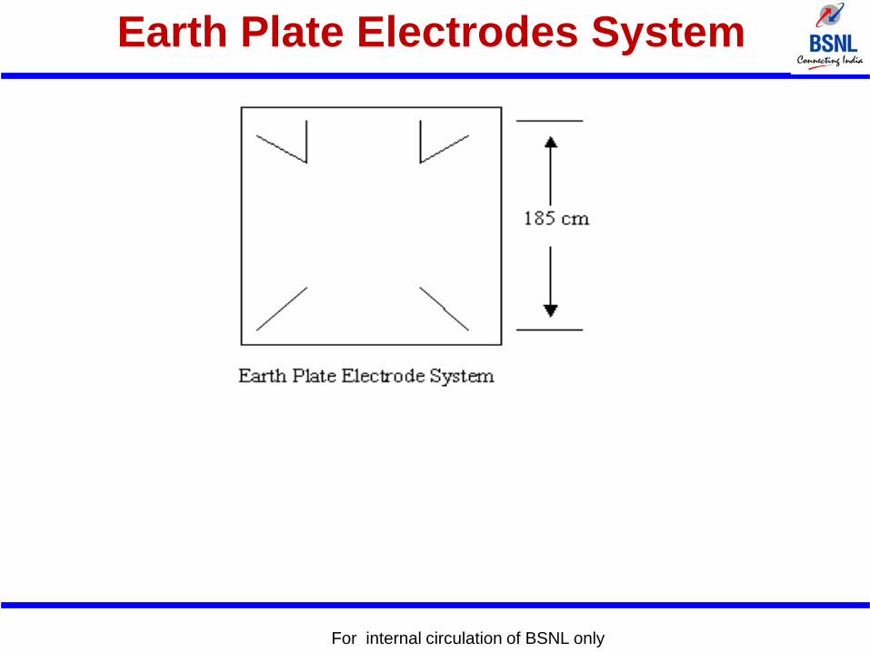
Earth Plate Electrodes System
• This consists of four galvanized iron plates of 14 swg 76
cms (2’ 6”) square plates. these four plates are placed
vertically and at diagonally opposite ends in an
excavation 185 cm square and of a depth sufficient to
reach damp soil. The depth should never be less than
250 cms and need not be close to the tails of plates as
possible as shown in the diagram:
For internal circulation of BSNL only
For internal circulation of BSNL only
Earth Plate Electrodes System
Standards for resistance of earth
electrode systems
• The resistance of earth electrode system should be as
possible and in any case should not exceed 2 ohms at
any time of the year. In cases where due to local
conditions, the resistance of earth electrode system
exceed 2 ohms, two or more similar earth electrode
system should be installed and spaced as far away as
possible form each other but not less than 375 cm from
the first electrode system.
For internal circulation of BSNL only
• The resistance of earth electrode system for electronic
system exchange should be less than 0.5 ohms.
For internal circulation of BSNL only
Rod or Pipe Electrodes
• Pipe electrode shall not be smaller than 40 mm internal
diameter if of galvanized iron. The length of the pipe
electrode shall be minimum 4.5 metre. If one electrode
fails to give the required resistance, no. of such
electrodes shall not be less than twice the length
electrodes. The G.I. Pipe shall be cut tapered at bottom
and provided with holes of 12 mm dia drilled not less
than 7.5 cm. from each other up to 2 mt. Length from
bottom.
For internal circulation of BSNL only
For internal circulation of BSNL only


