71
FeDERALEMERGENCY MANAGEMENTAGENCY FEMA --- / "Myl'-i Repair of Earthquake Damaged Concreteaand, Masonry Wall Biuildings FEDERALEMERGENCY MANA.GEMENTAGENCY FFMA30n8/ MaV199
FeDERALEMERGENCY MANAGEMENTAGENCY FEMA --- / "Myl'-i
Repair ofEarthquake Damaged
Concreteaand, Masonry WallBiuildings
FEDERALEMERGENCY MANA.GEMENTAGENCY FFMA30n8/MaV199

FEMA 308
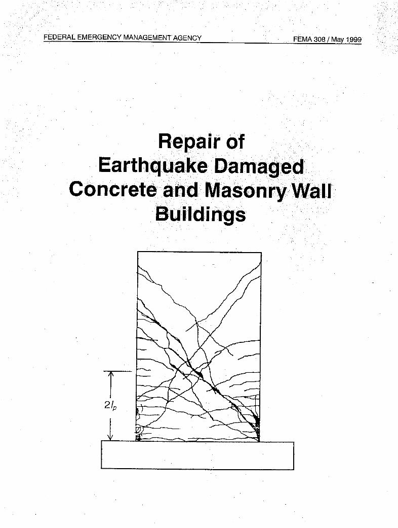
REPAIR OF EARTHQUAKE DAMAGED
CONCRETE AND MASONRY WALL BUILDINGS
Prepared by:
L\TCThe Applied Technology Council
555 Twin Dolphin Drive, Suite 550Redwood City, California 94065
Prepared for:
The Partnership for Response and RecoveryWashington, D.C.
Funded by:
Federal Emergency Management Agency
1998
I .. - I ~"2 I

Applied Technology Council
The Applied Technology Council (ATC) is a nonprofit, tax-exempt corporation estab-lished in 1971 through the efforts of the Structural Engineers Association of California.ATC is guided by a Board of Directors consisting of representatives appointed by theAmerican Society of Civil Engineers, the Structural Engineers Association of Califor-nia, the Western States Council of Structural Engineers Associations, and four at-largerepresentatives concerned with the practice of structural engineering. Each directorserves a three-year term.
The purpose of ATC is to assist the design practitioner in structural engineering (andrelated design specialty fields such as soils, wind, and earthquake) in the task of keep-ing abreast of and effectively using technological developments. ATC also identifiesand encourages needed research and develops consensus opinions on structural engi-neering issues in a nonproprietary format. ATC thereby fulfills a unique role in fundedinformation transfer.
Project management and administration are carried out by a full-time Executive Direc-tor and support staff. Project work is conducted by a wide range of highly qualified con-sulting professionals, thus incorporating the experience of many individuals fromacademia, research, and professional practice who would not be available from any sin-gle organization. Funding for ATC projects is obtained from government agencies andfrom the private sector in the form of tax-deductible contributions.
1998-1999 Board of Directors
Charles H. Thornton, President Edwin H. JohnsonEdwin T. Dean, Vice President Kenneth A. LuttrellAndrew T. Merovich, Secretary/ Newland J. Malmquist
Treasurer Stephen H. PelhamC. Mark Saunders, Past President Richard J. PhillipsJames R. Cagley Charles W. RoederArthur N. L. Chiu Jonathan G. ShippRobert G. Dean
Notice
This report was prepared under Contract EMW-95-C-4685 between the Federal Emer-gency Management Agency and the Partnership for Response and Recovery.
Any opinions, findings, conclusions, orrecommendations expressed in this publicationdo not necessarily reflect the views of the Applied Technology Council (ATC), thePartnership for Response and Recovery (PaRR), or the Federal Emergency Manage-ment Agency (FEMA). Additionally, neither ATC, PaRR, FEMA, nor any of their em-ployees makes any warranty, expressed or implied, nor assumes any legal liability or
responsibility for the accuracy, completeness, or usefulness of any information, prod-uct, or process included in this publication. Users of information from this publicationassume all liability arising from such use.
For further information concerning this document or the activities of the ATC, contactthe Executive Director, Applied Technolgy Council, 555 Twin Dolphin Drive, Suite550, Redwood City, California 94065; phone 650-595-1542; fax 650-593-2320; e-mail
atc @atcouncil.org.

Preface
Following the two damaging California earthquakes in1989 (Loma Prieta) and 1994 (Northridge), manyconcrete wall and masonry wall buildings were repairedusing federal disaster assistance funding. The repairswere based on inconsistent criteria, giving rise tocontroversy regarding criteria for the repair of crackedconcrete and masonry wall buildings. To help resolvethis controversy, the Federal Emergency ManagementAgency (FEMA) initiated a project on evaluation andrepair of earthquake-damaged concrete and masonrywall buildings in 1996. The project was conductedthrough the Partnership for Response and Recovery(PaRR), a joint venture of Dewberry & Davis ofFairfax, Virginia, and Woodward-Clyde FederalServices of Gaithersburg, Maryland. The AppliedTechnology Council (ATC), under subcontract to PaRR,was responsible for developing technical criteria andprocedures (the ATC-43 project).
The ATC-43 project addresses the investigation andevaluation of earthquake damage and discusses policyissues related to the repair and upgrade of earthquake-damaged buildings. The project deals with buildingswhose primary lateral-force-resisting systems consist ofconcrete or masonry bearing walls with flexible or rigiddiaphragms, or whose vertical-load-bearing systemsconsist of concrete or steel frames with concrete ormasonry infill panels. The intended audience is designengineers, building owners, building regulatoryofficials, and government agencies.
The project results are reported in three documents. TheFEMA306report,Evaluationof EarthquakeDamagedConcrete and Masonry Wall Buildings, BasicProcedures Manual, provides guidance on evaluatingdamage and analyzing future performance. Included inthe document are component damage classificationguides, and test and inspection guides. FEMA 307,Evaluationof EarthquakeDamagedConcreteandMasonry Wall Buildings, TechnicalResources, containssupplemental information including results from atheoretical analysis of the effects of prior damage onsingle-degree-of-freedom mathematical models,additional background information on the componentguides, and an example of the application of the basicprocedures. FEMA 308, The Repair of EarthquakeDamaged Concrete and Masonry WallBuildings,discusses the policy issues pertaining to the repair ofearthquake-damaged buildings and illustrates how theprocedures developed for the project can be used toprovide a technically sound basis for policy decisions. It
also provides guidance for the repair of damagedcomponents.
The project also involved a workshop to provide anopportunity for the user community to review andcomment on the proposed evaluation and repair criteria.The workshop, open to the profession at large, was heldin Los Angeles on June 13, 1997 and was attended by75 participants.
The project was conducted under the direction of ATCSenior Consultant Craig Comartin, who served as Co-Principal Investigator and Project Director. Technicaland management direction were provided by aTechnical Management Committee consisting ofChristopher Rojahn (Chair), Craig Comartin (Co-Chair), Daniel Abrams, Mark Doroudian, James Hill,Jack Moehle, Andrew Merovich (ATC BoardRepresentative), and Tim McCormick. The TechnicalManagement Committee created two Issue WorkingGroups to pursue directed research to document thestate of the knowledge in selected key areas: (1) anAnalysis Working Group, consisting of Mark Aschheim(Group Leader) and Mete Sozen (Senior Consultant)and (2) a Materials Working Group, consisting of JoeMaffei (Group Leader and Reinforced ConcreteConsultant), Greg Kingsley (Reinforced MasonryConsultant), Bret Lizundia (Unreinforced MasonryConsultant), John Mander (Infilled Frame Consultant),Brian Kehoe and other consultants from Wiss, Janney,Elstner and Associates (Tests, Investigations, andRepairs Consultant). A Project Review Panel providedtechnical overview and guidance. The Panel memberswere Gregg Borchelt, Gene Corley, Edwin Huston,Richard Klingner, Vilas Mujumdar, Hassan Sassi, CarlSchulze, Daniel Shapiro, James Wight, and EugeneZeller. Nancy Sauer and Peter Mork provided technicalediting and report production services, respectively.Affiliations are provided in the list of projectparticipants.
The Applied Technology Council and the Partnershipfor Response and Recovery gratefully acknowledge thecooperation and insight provided by the FEMATechnical Monitor, Robert D. Hanson.
Tim McCormickPaRR Task Manager
Christopher RojahnATC-43 Principal InvestigatorATC Executive Director
Repair of Earthquake Damaged Concrete and Masonry Wall Buildings HiiFEMA 308

.2
.2
.5
.14
.17
.18
.18
.................
Table of Contents
Preface ............ iii
List of Figures ..... .. ....... .......... .. . . vii
List of Tables ................. vii
List of Repair Guides ................. ix
Prologue.................................. o .. ... ....... ... ... ... .. xi
1. Introduction .
1.1 Purpose .
1.2 Scope ...............................
1.3 Basis.1.4 Document Overview .1.5 Limitations.
2. Background.2.1 Introduction .........................2.2 Experience in Recent Past Earthquakes2.3 Basic Policy Considerations .............2.4 Technical Impediments ................
............. ....1
............. ....1
............. ....1...................... ......................
...................................... 5
5
6
7
3. Performance-Based Policy Framework.3.1 Introduction ...........................
3.2 Basic Alternatives ......................
3.3 Damage Evaluation Procedure .3.3.1 Performance Objectives.3.3.2 Global Displacement Parameters3.3.3 Structural Components.
3.4 Performance Capacity and Loss .3.5 Restoration or Upgrade Procedure .3.6 Relative Seismic Demand .3.7 Relative Risk .
.... 9
.... 9
.... 9
.... 9... 10... 10... 10... 11... 12... 12... 13
3.8 Thresholds for Restoration and Upgrade.3.9 Policy Implications and Limitations of Component Acceptability and
Displacement Demand .3.10 Public Sector Policy Planning Recommendations.3.11 Private Policy Planning Recommendations.3.12 Summary ...............................................
4. Implementation....................................4.1 Introduction .....................................
4.2 Performance-Based Repair Design ...................4.3 Repair Technologies .
.................
.................
.................
................. 19
21
21
21
21
Repair of Earthquake Damaged Concrete and Masonry Wall Buildings
................
................
................
................
.........
.........
.........................
.........................
.........................
.........................
.........
.........
.........
................
................
................
................
..................
.........
.........
.........
.........
.........
.........
.........
.........
.........
.................
.................
.................
FEMA 308 v

4.3.1 Categories of Repairs .......................... 214.3.2 Nonstructural Considerations .......................... 224.3.3 Repair Guides .......................... 23
Glossary .......................... 43
Symbols .......................... 45
References .......................... 47
ATC-43Project Participants . . . 49
Applied Technology Council Projects And Report Information . . . 53.
Repair of Earthquake Damaged Concrete and Masonry Wall Buildings FEMA 308vi

List of Figures
Figure 2-1 Sensitivity of displacement to changes in force ............... ..................... 8
Figure 3-1 Capacity curves from nonlinear static procedures. ............ .................... 10
Figure 3-2 Global displacement capacities, dc, for various performance levels ....... ............ 10
Figure 3-3 Global displacement demand for undamaged, damaged, and restored/upgradedconditions................................................................ 11
Figure 3-4 Structural component force-deformation characteristics ............. ............... 11
Figure 3-5 Global displacement demands and capacities .................................... 13
Figure 3-6 Risk associated with damage acceptance, restoration, and upgrade for a specificperformance objective .13
Figure 3-7 Thresholds and performance limits for restoration and upgrade of earthquake-damaged buildings ........................................... 16
List of Tables
Table 3-1 Parameters governing whether damage is acceptable .................... 5......... 1
Table 3-2 Parameters governing whether restoration is acceptable ... ........... 15Table 4-1 Summary of repair procedures ....................................... .... 22
Repair of Earthquake Damaged Concrete and MasonryWall Buildings vi!FEMA 308

List of Repair Guides(See Section 4.3.3)
Title Page No.
Cosmetic Patching.......................... 24
Repointing Mortar .......................... 26
Crack Injection - Epoxy.......................... 28
Crack Injection - Grout .......................... 30
Spall Repair .......................... 32
Rebar Replacement .......................... 34
Wall Replacement .......................... 36
Structural Overlay - Concrete .......................... 38
Structural Overlay - Composite Fibers .......................... 40
Crack Stitching .......................... 42
Repair of Earthquake Damaged Concrete and Masony Wall Buildings
ID
CR1
CR2
CR3/SRl
SR2
SR3
SR4
SR5
SEl
SE2
SE3
FEMA 308

Prologue
This document is one of three to result from the ATC-43project funded by the Federal Emergency ManagementAgency (FEMA). The goal of the project is to developtechnically sound procedures to evaluate the effects ofearthquake damage on buildings with primary lateral-force-resisting systems consisting of concrete ormasonry bearing walls or infilled frames. They arebased on the knowledge derived from research andexperience in engineering practice regarding theperformance of these types of buildings and theircomponents. The procedures require thoughtfulexamination and review prior to implementation. TheATC-43 project team strongly urges individual users toread all of the documents carefully to form an overallunderstanding of the damage evaluation procedures andrepair techniques.
Before this project, formalized procedures for theinvestigation and evaluation of earthquake-damagedbuildings were limited to those intended for immediateuse in the field to identify potentially hazardousconditions. ATC-20, Procedures for PostearthquakeSafety Evaluation of Buildings, and its addendum, ATC-20-2 (ATC, 1989 and 1995) are the definitivedocuments for this purpose. Both have proven to beextremely useful in practical applications. ATC-20recognizes and states that in many cases, detailedstructural engineering evaluations are required toinvestigate the implications of earthquake damage andthe need for repairs. This project provides a frameworkand guidance for those engineering evaluations.
What have we learned?The project team for ATC-43 began its work with athorough review of available analysis techniques, fieldobservations, test data, and emerging evaluation anddesign methodologies. The first objective was tounderstand the effects of damage on future buildingperformance. The main points are summarized below.
* Component behavior controls globalperformance.
Recently developed guidelines for structuralengineering seismic analysis and design techniquesfocus on building displacement rather than forces asthe primary parameter for the characterization of
seismic performance. This approach models thebuilding as an assembly of its individualcomponents. Force-deformation properties (e.g.,elastic stiffness, yield point, ductility) control thebehavior of wall panels, beams, columns, and othercomponents. The component behavior, in turn,governs the overall displacement of the building andits seismic performance. Thus, the evaluation of theeffects of damage on building performance mustconcentrate on how component properties change asa result of damage.
* Indicators of damage (e.g., cracking,spalling) are meaningful only in light of themode of component behavior.
Damage affects the behavior of individualcomponents differently. Some exhibit ductile modesof post-elastic behavior, maintaining strength evenwith large displacements. Others are brittle and losestrength abruptly after small inelasticdisplacements. The post-elastic behavior of astructural component is a function of materialproperties, geometric proportions, details ofconstruction, and the combination of demandactions (axial, flexural, shearing, torsional) imposedupon it. As earthquake shaking imposes theseactions on components, the components tend toexhibit predominant modes of behavior as damageoccurs. For example, if earthquake shaking and itsassociated inertial forces and frame distortionscause a reinforced concrete wall panel to rotate ateach end, with in-plane distortion, statics defines therelationship between the associated bendingmoments and shear force. The behavior of the paneldepends on its strength in flexure relative to that inshear. Cracks and other signs of damage must beinterpreted in the context of the mode of componentbehavior. A one-eighth-inch crack in a wall panel onthe verge of brittle shear failure is a very seriouscondition. The same size crack in a flexurally-controlled panel may be insignificant with regard tofuture seismic performance. This is, perhaps, themost important finding of the ATC-43 project: thesignificance of cracks and other signs of damage,with respect to the future performance of a building,depends on the mode of behavior of the componentsin which the damage is observed.
Repair of Earthquake Damaged Concrete and Masonry Wall BuildingsFEMA 308

Prologue
* Damage may reveal component behaviorthat differs from that predicted by evaluationand design methodologies.
When designing a building or evaluating anundamaged building, engineers rely on theory andtheir own experience to visualize how earthquakeswill affect the structure. The same is true when theyevaluate the effects of actual damage after anearthquake, with one important difference. Ifengineers carefully observe the nature and extent ofthe signs of the damage, they can greatly enhancetheir insight into the way the building actuallyresponded to earthquake shaking. Sometimes theactual behavior differs from that predicted usingdesign equations or procedures. This is not reallysurprising, since design procedures must accountconservatively for a wide range of uncertainty inmaterial properties, behavior parameters, andground shaking characteristics. Ironically, actualdamage during an earthquake has the potential forimproving the engineer's knowledge of the behaviorof the building. When considering the effects ofdamage on future performance, this knowledge isimportant.
* Damage may not significantly affectdisplacement demand in future largerearthquakes.
One of the findings of the ATC-43 project is thatprior earthquake damage does not affect maximumdisplacement response in future, larger earthquakesin many instances. At first, this may seem illogical.Observing a building with cracks in its walls after anearthquake and visualizing its future performance inan even larger event, it is natural to assume that it isworse off than if the damage had not occurred. Itseems likely that the maximum displacement in thefuture, larger earthquake would be greater than if ithad not been damaged. Extensive nonlinear time-history analyses performed for the project indicatedotherwise for many structures. This was particularlytrue in cases in which significant strengthdegradation did not occur during the prior, smallerearthquake. Careful examination of the resultsrevealed that maximum displacements in timehistories of relatively large earthquakes tended tooccur after the loss of stiffness and strength wouldhave taken place even in an undamaged structure. Inother words, the damage that occurs in a prior,
smaller event would have occurred early in thesubsequent, larger event anyway.
What does it mean?The ATC-43 project team has formulated performance-based procedures for evaluating the effects of damage.These can be used to quantify losses and to developrepair strategies. The application of these procedureshas broad implications.
* Performance-based damage evaluation usesthe actual behavior of a building, asevidenced by the observed damage, toidentify specific deficiencies.
The procedures focus on the connection betweendamage and component behavior and theimplications for estimating actual behavior in futureearthquakes. This approach has several importantbenefits. First, it provides a meaningful engineeringbasis for measuring the effects of damage. It alsoidentifies performance characteristics of thebuilding in its pre-event and damaged states. Theobserved damage itself is used to calibrate theanalysis and to improve the building model. Forbuildings found to have unacceptable damage, theprocedures identify specific deficiencies at acomponent level, thereby facilitating thedevelopment of restoration or upgrade repairs.
o Performance-based damage evaluationprovides an opportunity for better allocationof resources.
The procedures themselves are technicalengineering tools. They do not establish policy orprescribe rules for the investigation and repair ofdamage. They may enable improvements in bothprivate and public policy, however. In pastearthquakes, decisions on what to do about damagedbuildings have been hampered by a lack of technicalprocedures to evaluate the effects of damage andrepairs. It has also been difficult to investigate therisks associated with various repair alternatives.Theframework provided by performance-based damageevaluation procedures can help to remove some ofthese roadblocks. In the long run, the proceduresmay tend to reduce the prevailing focus on the losscaused by damage from its pre-event conditions andto increase the focus on what the damage revealsabout future building performance. It makes little
Repair of Earthquake Damaged Concrete and Masonry Wall Buildings FEMA 308

Prologue
sense to implement unnecessary repairs to buildingsthat would perform relatively well even in adamaged condition. Nor is it wise to neglectbuildings in which the component behavior revealsserious hazards regardless of the extent of damage.
Engineering judgment and experience areessential to the successful application ofthe procedures.
ATC-20 and its addendum, ATC-20-2, weredeveloped to be used by individuals who might besomewhat less knowledgeable about earthquakebuilding performance than practicing structuralengineers. In contrast, the detailed investigation ofdamage using the performance-based procedures ofthis document and the companion FEMA 306 report(ATC, 1998a) and FEMA 307 report (ATC, 1998b)must be implemented by an experienced engineer.Although the documents include information inconcise formats to facilitate field operations, theymust not be interpreted as a "match the pictures"exercise for unqualified observers. Use of theseguideline materials requires a thoroughunderstanding of the underlying theory andempirical justifications contained in the documents.Similarly, the use of the simplified direct method toestimate losses has limitations. The decision to usethis method and the interpretation of the results mustbe made by an experienced engineer.
* The new procedures are different from pastdamage evaluation techniques and willcontinue to evolve in the future.
The technical basis of the evaluation procedures isessentially that of the emerging performance-based
seismic and structural design procedures. These willtake some time to be assimilated in the engineeringcommunity. The same is true for building officials.Seminars, workshops, and training sessions arerequired not only to introduce and explain theprocedures but also to gather feedback and toimprove the overall process. Additionally, futurematerials-testing and analytical research willenhance the basic framework developed for thisproject. Current project documents are initialeditions to be revised and improved over the years.
In addition to the project team, a Project Review Panelhas reviewed the damage evaluation and repairprocedures and each of the three project documents.This group of experienced practitioners, researchers,regulators, and materials industry representativesreached a unanimous consensus that the products aretechnically sound and that they represent the state ofknowledge on the evaluation and repair of earthquake-damaged concrete and masonry wall buildings. At thesame time, all who contributed to this projectacknowledge that the recommendations depart fromtraditional practices. Owners, design professionals,building officials, researchers, and all others with aninterest in the performance of buildings duringearthquakes are encouraged to review these documentsand to contribute to their continued improvement andenhancement. Use of the documents should providerealistic assessments of the effects of damage andvaluable insight into the behavior of structures duringearthquakes. In the long run, they hopefully willcontribute to sensible private and public policyregarding earthquake-damaged buildings.
Repair of Earthquake Damaged Concrete and Masonry Wall Buildings ; ~~~~~xiiiFEMA 308

Introduction
1.1 PurposeThe purpose of this document is to present practicalguidance for the repair and upgrading of earthquake-damaged buildings with primary lateral-force-resistingsystems consisting of concrete bearing walls, masonrybearing walls, or infilled frames. The guidance consistsof a policy framework for facilitating the determinationof the appropriate scope of repair or upgradingmeasures. This document also includes outlines ofspecific repair techniques that can address thecomponent damage common to these buildings. Thecriteria and procedures are based on the evaluation ofthe anticipated seismic performance of a subjectbuilding at three different times: in its conditionimmediately before the damaging earthquake (pre-event), in its damaged condition, and in its repaired orupgraded condition. This document may be used as atechnical resource to facilitate the settlement ofinsurance claims, the development of policy andstrategy for repair, or other appropriate purposes. Theintended users of the document are design engineers,building owners, building officials, insurance adjusters,and government agencies.
1.2 ScopeThis document is one of several to result from aresearch project on the evaluation and repair ofearthquake-damaged concrete and masonry wallbuildings. Concrete and masonry wall buildings includethose with vertical-load-bearing wall panels, with andwithout intermediate openings. In this document,concrete and masonry wall buildings also include thosewith vertical-load-bearing frames of concrete or steelthat incorporate masonry or concrete infill panels toresist horizontal forces. The specific recommendationsfor repair technologies developed for this projectprimarily address the type of damage normallyencountered in concrete and masonry wall buildings;however, the policy framework developed in thisdocument applies to buildings in general without regardto structural system.
The guidance on policies and techniques for repair ofearthquake damage in this document addresses:
1. The parameters normally considered in decisionson the scope of repair or upgrading for buildingsdamaged by earthquakes
2. The formulation of these parameters in terms of theanticipated seismic performance of buildings intheir pre-event, restored, and upgraded conditions
3. The process of evaluating anticipated seismic per-formance to decide whether to accept, restore, orupgrade earthquake-damaged buildings
4. The development of repair strategies to meet perfor-mance goals
5. Specific repair techniques to address damagedstructural components in concrete and masonry wallbuildings
1.3 BasisThe policy framework and repair techniques in thisdocument are based on the evaluation of the effects ofearthquake damage on the anticipated futureperformance of buildings. FEMA 306: The Evaluationof Earthquake-DamagedConcreteand MasonryWallBuildings- Basic ProceduresManual(ATC,1998a)documents the performance-based evaluationprocedures. The procedures and criteria in FEMA 306address:
1. The investigation and documentation of damagecaused by earthquakes
2. The classification of the damage for building com-ponents according to mode of structural behaviorand severity
3. The evaluation of the effects of the damage on theperformance of the building during future earth-quakes
4. The development of hypothetical measures thatwould restore the performance to that of the undam-aged building
FEMA 307: The Evaluation of Earthquake-DamagedConcreteand Masonry WallBuildings- TechnicalResources (ATC, 1998b) provides supplemental datathat facilitates use of the FEMA 306 procedures. Theevaluation procedures build, to the extent possible, onexisting performance-based procedures in the FEMA273 and FEMA 274 reports, NEHRP Guidelinesfor theSeismic Rehabilitation of Buildings (ATC, 1997a), andcompanion Commentary (ATC, 1997b) and the ATC-40report, Seismic Evaluation and Retrofit of ConcreteBuildings (ATC, 1996). The intention is to document
Repair of Earthquake Damaged Concrete and Masonry Wall Buildings
1.
FEMA 308 1

Chapter 1: Introduction
and adapt the existing state of knowledge rather than todevelop completely new techniques. This approach alsocontributes to consistency of language, nomenclature,and technical concepts among emerging proceduresintended for use by structural engineers.
As a part of the research program for FEMA 306, 307and this document (FEMA 308), two issues workinggroups focused on the key aspects of adapting andenhancing the existing technology to the evaluation andrepair of earthquake-damaged buildings. The generalscope of work for each group is outlined in FEMA 307.The scope of work for the Materials Working Groupincluded the review and summary of repair techniquesfor concrete and masonry wall buildings. The groupreviewed experimental and analytical research reports,technical papers, standards, manufacturers'specifications, and practical example applicationsrelating to the repair of damage in concrete andmasonry walls and infill panels. The primary interestwas the repair of earthquake damage to structuralcomponents. The review focused on materials andmethods of installation and tests for assessing theeffectiveness of repair techniques for cracking,crushing, and deterioration of concrete or masonry; andyielding, fracture, and deterioration of reinforcing steel.Based on the review, practical guidelines for damagerepair were developed and are contained in thisdocument (FEMA 308). These guidelines consist ofoutline specifications for equipment, materials, andprocedures required to execute the repairs as well ascriteria for quality control and verification of fieldinstallations. The efficacy and advisability of varioustechniques are discussed in relation to the objective ofrestoring and supplementing the force-deformationbehavior of individual components.
1.4 Document OverviewThis document comprises three major parts. First,background material on repair of earthquake-damagedbuildings is summarized in Chapter 2. This consists ofsome discussion of experiences of communities afterrecent past earthquakes. The result is the identificationof some common issues and parameters for earthquakerepair policies and procedures, as well as sometechnical impediments to the overall process.
Chapter 3 briefly reviews the performance-baseddamage evaluation procedures of FEMA 306. It alsointroduces a policy framework based on buildingperformance parameters. Recommendations are offered
to both public policy agencies and private-sectorbuilding owners to facilitate the use of the performance-based framework.
Finally, Chapter 4 discusses the implementation ofrepairs. Although conventional prescriptive approachesare acceptable alternatives in many simple cases, theuse of performance-based standards is recommendedfor general application. Typical repairs are categorizedaccording to their intended objective. Outlinespecifications for repairs typically applied to concreteand masonry wall buildings are tabulated.
1.5 LimitationsThe policy framework for repair presented in thisdocument incorporates parameters related to theperformance characteristics of individual buildings, theshaking severity of the damaging event, performanceobjectives for future events, thresholds for restorationand upgrading, and others. Policy decisions include theselection of specific limits or values for some of theseparameters. This document is not intended torecommend policy for the repair or upgrading ofbuildings beyond the use of the generic framework.Specific limits or values for controlling parameters arenot recommended in this document. In some cases,examples are used for illustration. These should not beconstrued by the user as policy recommendations.
Earthquakes can cause damage to both the structuraland the nonstructural components of buildings. Thisdocument addresses structural damage. The directevaluation of nonstructural damage is not included. Theeffects of structural damage on potential futurenonstructural damage can be addressed indirectly by theselection of appropriate seismic performance objectivesfor the evaluation procedure.
The term damage, when used in this document, refers tothe damage suffered during the damaging earthquakebythe building in its existing condition immediately beforethe earthquake. It is important to note that prior effectsof environmental deterioration, service conditions, andprevious earthquakes are considered to be pre-existingconditions and not part of the damage to be evaluated.
The procedures and criteria for evaluating and repairingdamage in this document have been based on thecurrent state of the knowledge on nonlinear inelasticbehavior of structures and structural components. Thisknowledge will expand over time. The evaluation
FEMA 3Ut�
Repair of Earthquake Damaged Concrete and Masonry Wall Buildings FEMA 3082

Chapter 1: Introduction
procedures and the information on component behaviormust be adapted appropriately to reflect newinformation as it becomes available.
The interpretation of damage as it relates to theperformance of buildings subject to earthquakes iscomplex and requires experience and judgment. Theseprocedures and criteria provide a framework for anengineer to apply experience and to formulatejudgments on the effects of earthquake damage onfuture performance. The validity of the results primarily
depend.on the capability of the engineer, or engineers,as opposed to the procedures and criteria themselves.
In the past, other methodologies have been used toevaluate buildings damaged in earthquakes and todesign repairs. If the procedures and criteria of thisdocument are applied retroactively to such buildings,the results may be different. Any difference is notnecessarily a reflection on the competence of theindividual or firm responsible for the original work.This should be judged on the basis of the proceduresand criteria that were available at the time of the work.
Repair of Earthquake Damaged Concrete and Masonry Wall BuildingsFEMA 308 3

Background
2.1 IntroductionThe effort to improve policy regarding the repair ofearthquake-damaged buildings benefits fromobservations on the recovery of communities after pastearthquakes. Recent experience in California and Japanreflect recent recovery efforts in urban and suburbansettings and a range of local damage intensities. Theseobservations lead to a synthesis of key policyconsiderations. They also reveal major technicalchallenges that must be met before policy can beimproved.
2.2 Experience in Recent PastEarthquakes
In 1975, an earthquake in northern California severelyaffected the small town of Oroville. Many buildings inits downtown central business district were closed dueto damage. The situation also raised concern for thesafety of other buildings, particularly unreinforcedmasonry (URM) buildings. With the assistance ofseveral engineers, the city council quickly passed anordinance allowing the reopening of buildings providedthat repairs designed by a civil or structural engineerreduced risk to an acceptable level (Olson and Olson,1992). These repairs did not need to comply withcurrent code requirements. The city also began todevelop criteria for evaluation and retrofit of allbuildings for seismic safety. Significant opposition fromthe local business community soon materialized,however, because of economic concerns over the costsof repairs and mitigative actions. After a period ofintense political wrangling, the city councilsignificantly weakened the repair ordinance anddefeated the proposal for evaluation and retrofit.
After the Loma Prieta earthquake of 1989, the city ofSan Francisco relied primarily on the San FranciscoBuilding Code (City and County of San Francisco,1989) as a standard for repair and upgrading ofdamaged buildings. The San Francisco code is based onthe Uniform Building Code (UBC), which is preparedby the International Conference of Building Officials(ICBO). The UBC allows repairs or alterations toexisting structures so long as the repairs themselvesconform to the provisions of the code. Absent a changein occupancy or other major change for the building,there is no UBC requirement to upgrade the entirebuilding to the current provisions of the UBC. San
Francisco modified this section of the code to requirethat the building be upgraded to full compliance (at the75% force level) when the repairs reach a certainthreshold. The existing trigger in the San Franciscocode at the time of Loma Prieta required fullcompliance (at the 75% force level) when 30% of thestructure was affected by the work. In practice, thisprovision has been extremely difficult to interpret andapply (Holmes, 1994).
Other cities implemented requirements for seismicupgrading based on a loss of lateral-load-carryingcapacity as a result of the damaging earthquake. InOakland, California, buildings damaged by the 1989Loma Prieta earthquake were required to be upgraded tofull compliance with the UBC if they lost a certainpercentage of their capacity. Buildings were dividedinto two risk categories, relatively high and normal.Those determined to have a high risk, based on type ofconstruction, size, and occupancy were required to bebrought into full compliance if they had lost more than10% of their lateral-load-resisting capacity. Those in thelower-risk group could lose 20% before full upgradewas required. Exceptions to full compliance could beissued by the building official for buildings of historicalsignificance and for those where the cost wasconsidered economically unfeasible. Nonetheless, theseexceptions still were required to conform to the 1973UBC and the California State Historic Building Code,where applicable.
The town of Los Gatos, a small community locatedrelatively near the epicenter of the 1989 Loma Prietaearthquake, suffered extensive damage, particularly toits historic area. Rather than adopt standards that wouldbe applied to all types of buildings and observeddamaged conditions, Los Gatos developed policiesbased on five categories of damaged buildings. Theseincluded historic buildings, unreinforced masonrybuildings, older wood-frame dwellings, oldercommercial buildings of various types, and damagedmasonry chimneys (Russell, 1994). The URM buildingswere required to be brought into compliance with astandard essentially equivalent to Division 88 of the LosAngeles Building Code (City of Los Angeles, 1985).This is a prescriptive model building ordinance directedat risk reduction performance for unreinforced masonrybuildings. Damaged buildings other than the URMstructures were required to have repairs designed tomeet 75% of the lateral-force requirements of the 1985
Repair of Earthquake Damaged Concrete and Masonry Wall Buildings
2.
FEMA 308 5

Chapter 2: Background
edition of the UBC. This was the current code in effectin Los Gatos at the time of the earthquake. Further, theowner's engineer was allowed to prescribe repair orstrengthening only for those structural elements foundto have suffered damage. In effect, this policy wasconsistent with the requirements for alterations andrepairs in the Uniform Building Code.
The city of Santa Cruz, located very close to theepicenter of the 1989 Loma Prieta earthquake, alsosuffered severe damage to its downtown area. The citypassed an ordinance requiring all damaged buildings tomeet the lateral-force requirements of the 1970 UBC.
Santa Clara County near San Jose allowed damagedURM buildings to be repaired by upgrading to therequirements of their URM ordinance, which waspassed immediately after the 1989 Loma PrietaEarthquake. Their requirements are similar to Division88 in Los Angeles.
Damage caused by the Northridge earthquake in 1994in southern California was greater overall and morewidespread than damage caused by the Loma Prietaearthquake. Repair requirements varied by localjurisdiction (CSSC, 1994). In the City of Los Angeles,when the damage at a floor resulted in less than a tenpercent loss of capacity along any single line ofresistance, the damaged sections could be replaced withthe same construction. If the damage in any single lineof resistance exceeded 10% of capacity, all componentsin the line were required to be brought into full codecompliance. If the total loss of capacity at any floorexceeded 50%, the entire lateral-force-resisting systemof the entire floor had to be brought into fullcompliance. Because of the technical difficulty ininterpreting these requirements, the recommendationsof individual engineers were accepted in most cases.
In 1991, the Japan Building Disaster PreventionAssociation issued guidelines for the inspection andrestoration of earthquake-damaged buildings (Sugano,1996). These guidelines were generally used in theKobe area following the earthquake in 1995. Theoptions for dealing with damaged buildings in theseguidelines include acceptance of the building in itsdamaged condition, repair to its pre-event condition,strengthening to a level greater than its pre-eventcondition, or demolition. The recommended actiondepends on two factors. The first is the level of damagethat was sustained during the damaging event. There arefive classifications for the degree of damage ranging
from "slight" to "collapse". Procedures are provided tocategorize the degree of damage based on the damageobserved in the field. The second factor determining thedegree of repair or upgrade required for the building isthe intensity of shaking in the vicinity of the building.This is designated in accordance with the JapaneseMeteorological Agency intensity scale, which has fivelevels of shaking intensity. This scale is qualitative andsimilar to the Modified Mercalli Intensity scale used inthe United States. These guidelines recognize that thelevel of repair or upgrade depends both on the amountof damage and on the intensity of shaking to which thebuilding was subjected. It differs from the approach ofthe City of Oakland and others who established a loss-of-capacity criterion that apparently applies regardlessof the intensity of shaking.
2.3 Basic Policy ConsiderationsAll communities in past earthquakes addressed thechallenge of recovery and reconstruction their ownways. In spite of this, observations on these experienceslead to several general conclusions and keyconsiderations for future policy:
1. The economic impact of earthquakes is a major fac-tor in the implementation of policies for repair andupgrading after an event. A damaging earthquakepresents particularly difficult and complex prob-lems for individual building owners and the generalcommunity. Owners may be confronted with largerepair costs along with a business downturn, bothcaused by the earthquake. It is in the community'slong-term interest to require restoration or upgrad-ing of damaged buildings to avoid similar or greaterlosses in future earthquakes. In the short term, how-ever, restrictive policies for repair can restrain vitaleconomic recovery. Effective policy to deal withthis situation is a balance of often-competingimperatives including, for example, public safety,private property rights, historic preservation, urbanplanning, economic development, and ethical andlegal considerations.
2. There is a virtually complete lack of standardsdirected toward the postearthquake repair of dam-aged buildings. Most jurisdictions rely upon someadaptation of an existing code or model buildingordinance for these guidelines. These adaptationsare developed after the event in a reactive mannerby city governments and engineers.
Repair of Earthquake Damaged Concrete and Masonry Wall Buildings FEMA 3086

Chapter 2: Background
3. The policies for specific buildings are related totheir occupancy and function. It seems reasonableto hold important buildings to a somewhat higherstandard than others. The risk of failure associatedwith damage in a hospital is greater than that forsingle-family residences.
4. The vulnerability associated with different buildingtypes is a factor. Older buildings or those withstructural systems known to pose greater risks dur-ing earthquakes (e.g., URM) are often held to morestringent requirements.
5. Insurance companies and agencies tend to measurelosses by comparing the damaged condition ofbuildings to their pre-event condition. While thispolicy limits the liability of the insurer, it does littleto reduce future losses, particularly for largerevents.
6. There is a tolerance for some amount of damageduring an earthquake. This seems logically to berelated to the intensity of shaking of the damagingearthquake. If a building suffers a small amount ofdamage in a small or moderate event, most commu-nities are willing to accept this damage, or, at themost, require that the building be brought back toits previous condition. On the other hand, whenbuildings suffer a large amount of damage in asmall or moderate event, the tolerance for accep-tance of the restoration to the previous condition isless. This attitude is related to the economic consid-erations discussed above.
2.4 Technical ImpedimentsExperience from recent past earthquakes demonstratesthat technical improvement in engineering standards forthe evaluation and repair of buildings would enhanceand facilitate the recovery. Holmes (1994) summarizedthe primary impediments to effective standards for theevaluation and repair of earthquake damage. These areconsolidated and summarized as follows:
1. Lack offormalized methods for analyzing the real-isticeffectsof earthquakeshakingand resultingdamageon theperformanceof buildingsand theircomponents. Traditionally, the focus of structuralanalysis and design has been on forces. This is dueto the fact that the most obvious structural demandthat most buildings face are their own weight andthe imposed vertical load. These are easily and
acceptably treated as static forces. Over the years, ithas become increasingly clear that the dynamicloads imparted to buildings by earthquakes are fun-damentally different from static loads. The magni-tude of the demand depends on the weight andstiffness of the building. Inevitably, the structureyields to dissipate energy during an earthquake.When it does, ductility, the ability to deform inelas-tically without abrupt loss of strength, is a criticalcapacity parameter. Stiffness, energy dissipation,and ductility are all dependent on displacements, asis damage.
Traditional analyses of forces assume linearly-elastic structural response. Therefore, the globaldemand is reduced and the allowable componentforce capacities are increased to account indirectlyfor inelastic behavior. The actual globaldisplacement of the structure and the distortion ofits components remain obscure, at best. Sincedamage depends on the actual displacements, thecondition of the structure for a specific level offorce is very difficult to characterize. This can bevisualized by examining a typical inelastic capacitycurve for a building (see Figure 2-1). As thestructure begins to yield, the curve generallyflattens with respect to the displacement axis. In theinelastic region, a small change in force can resultin a large change in displacement. This is afundamental improvement in analysis that iscurrently emerging in engineering practice (ATC,1996; 1997a,b).
The key to realistic evaluation of the effects ofearthquake damage on performance is amethodology that focuses on displacements ratherthan forces.
2. Limited information on the behavior of structuralcomponents particularly on the effectiveness ofrepairs, the relationship between repair techniquesanddamageintensity,andthe effectsof local repairon global behavior Traditional codes and structuralanalysis techniques address structural componentbehavior in the linear range. Little data on inelasticbehavior have been formally compiled from avail-able research and test results. Observations of dam-age (e.g., crack size and extent) to components havenot been related to changes in structural properties.There are few standards for design and constructionrelated to the repairs normally used for damagedstructural components, nor are there readily avail-
Repair of Earthquake Damaged Concrete and Masonry Wall Buildings 7FEMA 308

Chapter 2: Background
Figure 2-1 Sensitivity of displacement to changesin force
able data on the effect of repairs on structural prop-erties.
The state of knowledge on component behaviorneeds to be documented and augmented asnecessary to relate damage (and repair) to structuralperformance.
3. Inadequate methods of measuring the significanceof damage with respect tofuture risks. When con-sidering what to do with a building damaged by anearthquake, a logical question is: "How does thedamage affect what will happen in a future earth-quake?" Design codes and conventional engineer-ing methodologies are prescriptive, and they do not
provide specific insight into seismic performance ofnew or damaged existing buildings. The costs toupgrade a damaged building to current code provi-sions are rarely trivial. The implication of a com-munity building department requirement for suchupgrade work is that the future consequences ofearthquakes to the community are worth the price.Similarly, the decision by a building owner toaccept a damaged building without repair is tacitacceptance of the future costs.
Effective earthquake repair policy and individualdecisions require better estimates of future seismicperformance.
Repair of Earthquake Damaged Concrete and Masonry Wall Buildings
Force
Parameter,F
Small ___change iin force T I I
Capacity curve
_4 _0-i DisplacementLarge change in Parameter, ddisplacement
FEMA 3088

Performance-Based PolicyFramework
3.1 IntroductionIn practice, successful recovery after a damagingearthquake depends on effective policies and acooperative effort between the private and publicsectors. The action to be taken on a damaged building isultimately the responsibility of the owner. Normally,however, the owner's options are constrained throughbuilding regulations intended to protect public safetyand to reduce future economic losses. The experience inpast earthquakes outlined in Chapter 2 suggests thatpolicy planning for recovery in advance of earthquakesmight greatly improve the process. Such planning couldaddress key considerations encountered after pastearthquakes. The performance-based procedures for theevaluation of earthquake-damaged buildings presentedin FEMA 306 and FEMA 307 can provide improvedtechnical information to facilitate both the planning andrecovery efforts. These procedures allow policies anddecisions to be fundamentally based on estimates of theperformance of damaged, restored, or upgradedbuildings.
3.2 Basic AlternativesThere are a number of alternatives for dealing with abuilding that has been damaged by an earthquake. Forthe purposes of developing a policy framework tofacilitate the decision-making process, three alternativesare considered:
* Accept the building for continued use in its damagedcondition. Sometimes the damage is obviouslyslight, implying that the building is only marginallyworse off than before the damaging earthquake. Ifthe damage is greater and the building seems moreprone to future damage, perhaps the occupancy canbe changed to reduce the risk and, at the same time,avoid repairs.
* Restore the building to its pre-event condition. Itseems logical to fix the damage that was done. Infact, this is the traditional approach in the insuranceindustry. The restored building would behave infuture earthquakes as it would have in its pre-eventcondition. The risks would be no greater than beforethe damaging event.
* Upgrade the building to a condition of improvedseismic performance compared to its pre-event
condition. Earthquake damage can reveal significantdeficiencies in buildings. The risks associated withthe building in future earthquakes, even in a restoredcondition, might be too large. In this case, the repairsare designed to improve the future performance andto reduce risks.
Selecting among these basic alternatives for a damagedbuilding requires consideration of all of the policyissues outlined in Chapter 2. The decision process andthe alternatives themselves imply a capability to answera fundamental technical question: How can theacceptability of a building's anticipated earthquakeperformance be measured? A benchmark is needed tocompare the performance of the building in damaged,restored, and upgraded states.
3.3 Damage EvaluationProcedure
There has been a tendency to attempt to gauge the effectof earthquake damage by estimating the loss of lateral-force-resisting capacity of the structure (Hanson, 1996).It has been assumed that this loss can be related to theobserved width and extent of concrete and masonrycracks in damaged shear-wall buildings, for example. Inreality, there is widespread disagreement on the effectof cracking on capacity and skepticism on the suitabilityof force capacity itself as a parameter for measuringdamage.
Recent progress in the development of performance-based evaluation techniques allows a more meaningfulmeasurement of the effect of damage on concrete andmasonry wall buildings (FEMA 273/274, and ATC-40).Performance-based procedures characterize the effectsof earthquake shaking on structures in terms ofdisplacement limit states. The adaptation of theseprocedures to the evaluation of earthquake-damagedbuildings is presented in FEMA 306. The evaluationprocedure assumes that when an earthquake causesdamage to a building, a competent engineer can assessthe effects, at least partially, through visual inspectionaugmented by investigative tests, structural analysis,and knowledge of the building construction. Bydetermining how the structural damage has changedstructural properties, it is possible to compareanalytically the future performance of the damagedbuilding with that of the building in its undamagedcondition. It is also feasible to investigate the
Repair of Earthquake Damaged Concrete and Masonry Wall Buildings
3.
FEMA 308
Chapter 3: Performance-Based Policy Framework
effectivenessof potential measures to restore or upgradethe damaged building.
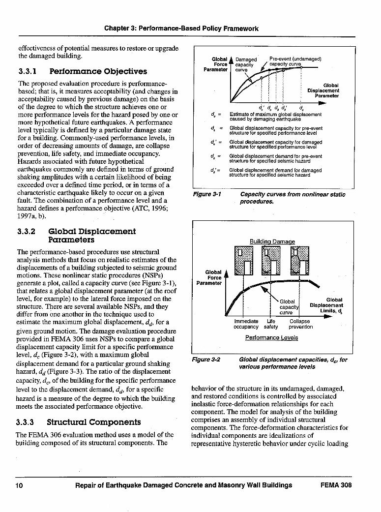
3.3.1 Performance ObjectivesThe proposed evaluation procedure is performance-based; that is, it measures acceptability (and changes inacceptability caused by previous damage) on the basisof the degree to which the structure achieves one ormore performance levels for the hazard posed by one ormore hypothetical future earthquakes. A performancelevel typically is defined by a particular damage statefor a building. Commonly-used performance levels, inorder of decreasing amounts of damage, are collapseprevention, life safety, and immediate occupancy.Hazards associated with future hypotheticalearthquakes commonly are defined in terms of groundshaking amplitudes with a certain likelihood of beingexceeded over a defined time period, or in terms of acharacteristic earthquake likely to occur on a givenfault. The combination of a performance level and ahazard defines a performance objective (ATC, 1996;1997a, b).
3.3.2 Global DisplacementParameters
The performance-based procedures use structuralanalysis methods that focus on realistic estimates of thedisplacements of a building subjected to seismic groundmotions. These nonlinear static procedures (NSPs)generate a plot, called a capacity curve (see Figure 3-1),that relates a global displacement parameter (at the rooflevel, for example) to the lateral force imposed on thestructure. There are several available NSPs, and theydiffer from one another in the technique used toestimate the maximum global displacement, dd, for agiven ground motion. The damage evaluation procedureprovided in FEMA 306 uses NSPs to compare a globaldisplacement capacity limit for a specific performancelevel, d, (Figure 3-2), with a maximum globaldisplacement demand for a particular ground shakinghazard, dd (Figure 3-3). The ratio of the displacementcapacity, dc, of the building for the specific performancelevel to the displacement demand, dd, for a specifichazard is a measure of the degree to which the buildingmeets the associated performance objective.
3.3.3 Structural ComponentsThe FEMA 306 evaluation method uses a model of thebuilding composed of its structural components. The
Figure 3-1 Capacity curves from nonlinear staticprocedures.
Building Damar e
GlobalForce
Parameter
Global Globalcapacity Displacement^ curyeLimits,d,
Immediate Life Collapseoccupancy safety prevention
Performance Levels
Figure 3-2 Global displacement capacities, dc, forvarious performance levels
behavior of the structure in its undamaged, damaged,and restored conditions is controlled by associatedinelastic force-deformation relationships for eachcomponent. The model for analysis of the buildingcomprises an assembly of individual structuralcomponents. The force-deformation characteristics forindividual components are idealizations ofrepresentative hysteretic behavior under cyclic loading
Repair of Earthquake Damaged Concrete and Masonry Wall Buildings
Global Damaged Pre-event(undamaged)Force capacity / capacitycurve
Parameter cure.
//| g g l ~~~GlobalDisplacement
Parameter
do' o d, d .d= Estimateof maximumglobaldisplacement
causedby damagingearthquake
d= Globaldisplacementcapacityfor pre-eventstructurefor specifiedperformancelevel
d' = Global displacementcapacityfor damagedstructurefor specifiedperformancelevel
dd = Global displacementdemandfor pre-eventstructurefor specifiedseismichazard
dd'= Globaldisplacementdemandfor damagedstructure for specifiedseismic hazard
FEMA 308

Chapter 3: Performance-Based Policy Framework
Figure 3-3 Global displacement demand forundamaged, damaged, and restored!upgraded conditions
conditions (Figure 3-4). For a given globaldisplacement of a structure subjected to a given lateralload pattern, there is an associated deformation for eachof the structural components of the building. Sinceinelastic deformation indicates component damage,then the maximum global displacement, dd, to occurduring an earthquake represents a structural damagestate for the building in terms of inelastic deformationsfor each of its components. The capacity of a givenstructure for a given performance level is represented bythe maximum global displacement, dc, at which thedamage is on the verge of exceeding the limit for thespecific performance level. For example, the collapse-prevention capacity of a building might be the roofdisplacement at which the associated damage wouldresult in one or more of the column components beingin danger of imminent collapse.
At the beginning of the evaluation process, the engineeridentifies basic components and documents the damageto each. The global displacement parameters for the
Figure 3-4 Structural component force-deformationcharacteristics
building are calculated using component properties forthe pre-event conditions (dc and dd).The structuralproperties of the components then are modified toreflect the effects of the observed damage using factorscontained in FEMA 306 supplemented by additionalinformation contained in FEMA 307. This allows theevaluation of the global displacement parameters for thebuilding in its damaged condition (,d' and dd).Information also is provided to modify componentproperties to reflect the effects of repairs to restore orupgrade on global displacement parameters (dc andd; ) for the building.
3.4 Performance Capacity andLoss
The ratios of global displacement limits or capacities(dr, d', d2 ) for a specific performance level to the
C
corresponding displacement demands (dd,d', d; ) for aspecific seismic hazard define indices of measurement(PEP, P*) of the ability of an undamaged ( ), damaged('), or restored or upgraded (*) building to meet aspecific performance objective (see Figure 3-1). Theseindices are:
Repair of Earthquake Damaged Concrete and Masonry Wall Buildings
Pre-event Building
I7:~~~21~Performance 4 de
LA ~~~~~~~~~~Time
Prgven t E acetate Nmgate
Damaaed BuildinadF]Damacang
EatquakeWA.~M
event ~ ntermetate' PerortrrrSr97tate Damagetate Damage tate(')
Restored or UDaradedBuilding
Time
Prg-event '" Restoration PerfracState q2t pgrade Damage ae(
For.e *F Backbone
Actualhystereticbehavior
(a) Backbonecurvefromactualhystereticbehavior
F Backbone F
I,CvIdealized l C, D B.C, D
14 \behvior 1(1E
Ductile Semi-ductile Brittle(deformationcontrolled) (forcecontolled)
(b) Idealizedcomponentbehaviorfrombackbonecurves
11FEMA 308
Chapter 3: Performance-Based Policy Framework
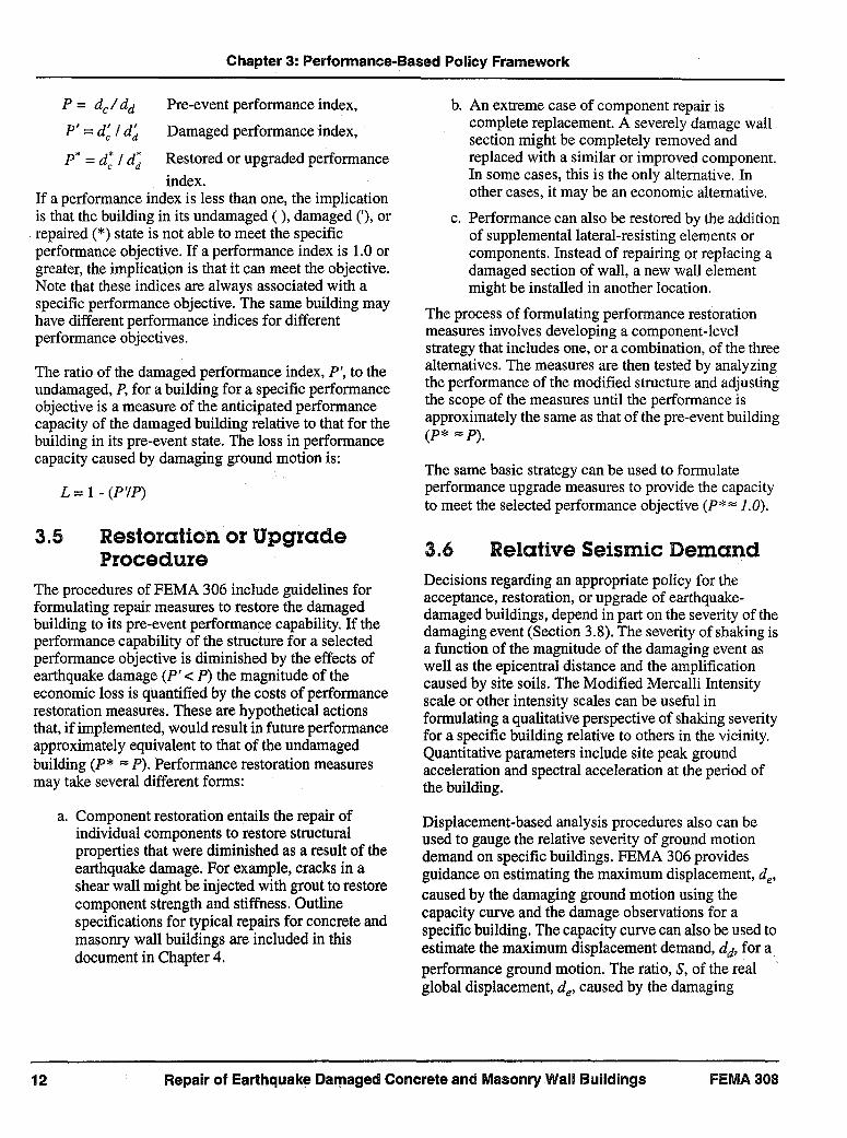
P = d /dd Pre-event performance index,
P = dc I dd Damaged performance index,
P = d* I dd* Restored or upgraded performance
index.If a performance index is less than one, the implicationis that the building in its undamaged ( ), damaged ('), orrepaired (*) state is not able to meet the specificperformance objective. If a performance index is 1.0 orgreater, the implication is that it can meet the objective.Note that these indices are always associated with aspecific performance objective. The same building mayhave different performance indices for differentperformance objectives.
The ratio of the damaged performance index, P', to theundamaged, P, for a building for a specific performanceobjective is a measure of the anticipated performancecapacity of the damaged building relative to that for thebuilding in its pre-event state. The loss in performancecapacity caused by damaging ground motion is:
L = 1 - (P'IP)
3.5 Restoration or UpgradeProcedure
The procedures of FEMA 306 include guidelines forformulating repair measures to restore the damagedbuilding to its pre-event performance capability. If theperformance capability of the structure for a selectedperformance objective is diminished by the effects ofearthquake damage (P' < P) the magnitude of theeconomic loss is quantified by the costs of performancerestoration measures. These are hypothetical actionsthat, if implemented, would result in future performanceapproximately equivalent to that of the undamagedbuilding (P* =P). Performance,restoration measuresmay take several different forms:
a. Component restoration entails the repair ofindividual components to restore structuralproperties that were diminished as a result of theearthquake damage. For example, cracks in ashear wall might be injected with grout to restorecomponent strength and stiffness. Outlinespecifications for typical repairs for concrete andmasonry wall buildings are included in thisdocument in Chapter 4.
b. An extreme case of component repair iscomplete replacement. A severely damage wallsection might be completely removed andreplaced with a similar or improved component.In some cases, this is the only alternative. Inother cases, it may be an economic alternative.
c. Performance can also be restored by the additionof supplemental lateral-resisting elements orcomponents. Instead of repairing or replacing adamaged section of wall, a new wall elementmight be installed in another location.
The process of formulating performance restorationmeasures involves developing a component-levelstrategy that includes one, or a combination, of the threealternatives. The measures are then tested by analyzingthe performance of the modified structure and adjustingthe scope of the measures until the performance isapproximately the same as that of the pre-event building(P* =P)
The same basic strategy can be used to formulateperformance upgrade measures to provide the capacityto meet the selected performance objective (P* 1.0).
3.6 Relative Seismic DemandDecisions regarding an appropriate policy for theacceptance, restoration, or upgrade of earthquake-damaged buildings, depend in part on the severity of thedamaging event (Section 3.8). The severity of shaking isa function of the magnitude of the damaging event aswell as the epicentral distance and the amplificationcaused by site soils. The Modified Mercalli Intensityscale or other intensity scales can be useful informulating a qualitative perspective of shaking severityfor a specific building relative to others in the vicinity.Quantitative parameters include site peak groundacceleration and spectral acceleration at the period ofthe building.
Displacement-based analysis procedures also can beused to gauge the relative severity of ground motiondemand on specific buildings. FEMA 306 providesguidance on estimating the maximum displacement, de,caused by the damaging ground motion using thecapacity curve and the damage observations for aspecificbuilding. The capacity curve can also be used toestimate the maximum displacement demand, dd, for aperformance ground motion. The ratio, S, of the realglobal displacement, de, caused by the damaging
Repair of Earthquake Damaged Concrete and Masonry Wall Buildings FEMIA 308

Chapter 3: Performance-Based Policy Framework
ground motion to the hypothetical displacementdemand, dd, for the performance ground motion is anindex of relative displacement demand and isrepresented as:
S = de Idd
The relative displacement demand provides animproved and unambiguous measure of the demand onthe building associated with the damaging earthquakefor several reasons. First, it is a measure that appliesdirectly to the specific building and site. Secondly, thebasis of measurement, displacement, is a better index ofdamage for buildings than acceleration. Finally, theindex is normalized relative to a defined performanceobjective.
3.7 Relative RiskThe capacity curve for a pre-event ( ), damaged ('), orrepaired (*) building allows one to estimate
Figure3-5 Global displacement demandsandcapacities
displacement demands for various levels of seismichazard as shown in Figure 3-5. These may be generatedusing nonlinear static procedures according to therecommendations in FEMA 306, in conjunction withthe appropriate capacity curve. In Figure 3-5 these areplotted on the upper horizontal axis noting their chanceof exceedance in 50 years. Component acceptabilitycriteria in conjunction with capacity curves also can be
used to define global displacement limits for variousperformance levels (e.g., immediate occupancy, lifesafety, collapse prevention). These are shown inFigure 3-5 along the lower horizontal axis. Thecombined plot provides a complete picture of the risksassociated with the particular repair alternative.
Global displacement demand for various repairalternatives can also be plotted versus a risk parameteras shown in Figure 3-6. The intersection of a globaldisplacement capacity value, for a selected performancelevel, with the corresponding displacement demandcurve allows an estimate of the risk that theperformance level would be exceeded for a given repairalternative. Doing this for several repair alternatives, as
Figure 3-6 Risk associated with damageacceptance,restoration, and upgradefora specific performance objective
shown in Figure 3-6, provides a comparison of the risksassociated with each alternative for the selectedperformance level. For example, suppose that theperformance level of interest is life safety. Figure 3-6illustrates that the chance that the global displacementdemand would exceed the life safety capacity of thedamaged structure is slightly higher than 20% in fiftyyears. Restoration of the structure to its pre-eventcondition would reduce the life safety risk to less than10%. The upgrade could reduce risk to just above 2% orapproximately ten times less than the damaged structurein this illustration.
Repair of Earthquake Damaged Concrete and Masonry Wall Buildings
Seismic Hazard LevelsGlobal (chanceof exceedance in 50 yrs.) GlobalForce Displacement
Parameter 0o% 10% 2% sl Demand
undamaged ()damaged ('), orrepaired (*)
city curve
-| >-.GIobalImmediate Life Collapse Displacementoccupancy safety prevention Capacity
Performance Levels d
_Displacementdemandcurves
Damaged,ddRestored,ddUpgraded,d*
GlobalDisplacement, d
Upgraded,d.'
Displacementcapacities
FEMA 308 13

Chapter 3: Performance-Based Policy Framework
3.8 Thresholds for Restorationand Upgrade
The decision on an appropriate course of action (acceptdamage, restore, or upgrade) for a specific buildingdamaged during an earthquake depends on a number ofinterrelated factors discussed below:
a. Relative Severity of Damaging GroundMotion.The tolerance for damage caused by relativelylarge earthquake ground motions is logicallygreater than if the same damage were caused bysmall ground motions. It makes sense that abuilding significantly damaged by small groundmotions is a good candidate for upgrading. Afterearthquake ground motions at about the designlevel for which damage is expected, a lessrestrictive policy on upgrading will facilitate theeconomic recovery of the community.
b. Theacceptabilityof performancecharacteristicsof the building after the damaging earthquake.If the damaged building is capable of meetingreasonable performance objectives in itsdamaged state, repair or upgrading may beunnecessary. It is also possible that short-termperformance objectives, lower than thoseappropriate for the longer term, may bereasonable to use in some circumstances,eliminating the need for immediate action.
c. The acceptabilityof performancecharacteristicsof the building before the damaging earthquake.The decision between restoration and upgradingis largely controlled by the acceptability of therestored performance, which would be equivalentto that before the earthquake. It is not logical torestore a building to a poor level of expectedperformance.
d. The change in performance characteristics of thebuilding caused by the damaging earthquake.If the damaging earthquake causes a largedecrease in the performance characteristics of abuilding, restoration or upgrading are obviouslymore advisable than if the loss were small. Smalllosses, particularly for large earthquakes, areoften acceptable.
e. Nonseismic issues related to the condition anduse of the building. Nonseismic deficiencies(e.g., disabled access, fire and life safety,programmatic, maintenance) are importantconsiderations. So is the anticipated future use of
a building and any change in appropriate seismicperformance objectives. It makes little sense toextend the life of a building significantly withoutaddressing seismic deficiencies.
Some of these factors governing decisions onacceptance, restoration, or upgrading have nofundamental technical basis. The rationale for allowingsome leeway in these decisions to account fornontechnical considerations is based on the precedentestablished in past earthquakes and common sense. It ishelpful, however, to establish quantifiable parameters torepresent the results of judgement and experience.
The performance indices for the building in its pre-event (P) and damaged (P) condition can be determinedusing the relative performance analysis procedures ofFEMA 306. Component acceptability and globaldisplacement demand control the thresholds forrestoration and repair because the performance indexfor both the pre-event structure (P) and the damagedstructure (P') are defined as the ratio of globaldisplacement capacity (d, or d,') to the globaldisplacement demand (dd or ddt). The behavior ofindividual components, as discussed in Section 3.3.3and FEMA 306, governs global displacementcapacities. Performance loss, L, is a function of theperformance indices.
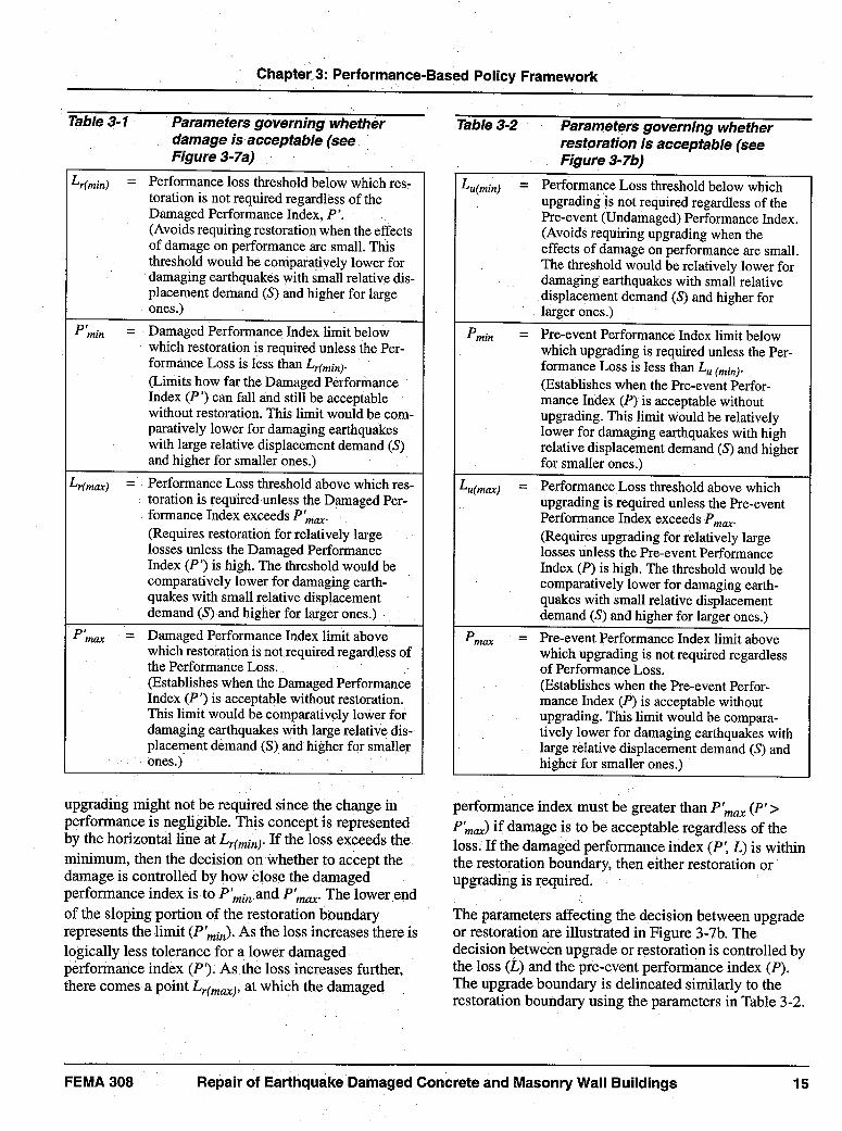
Boundaries between acceptance and restoration, andbetween acceptance or restoration and upgrading can bedefined as in Tables 3-1 and 3-2. The parametersintroduced in these tables can be plotted, for a givendamaging earthquake with relative displacementdemand, S. as illustrated in Figure 3-7a and b and usedas a guide for the need for restoration or upgrading of adamaged building.
The performance loss (L) for the selected objective isdetermined and plotted as a horizontal line as inFigure 3-7a and b. Figure 3-7a illustrates the boundarybetween restoration or upgrade and acceptance of thedamage. Figure 3-7b illustrates the boundary betweendamage acceptance (or restoration) and upgrade.Turning first to Figure 3-7a, the point (P', L) is used todetermine if the damage can be accepted. If thedamaged building is capable of meeting reasonableperformance objectives, repair or upgrading isunnecessary. The restoration boundary betweenacceptance of the damage and the need for restoration;or upgrade is defined by the parameters in Table 3-1. Ifthe performance loss (L) is small, then restoration or
Repair of Earthquake Damaged Concrete and Masonry Wall Buildings FEMA 30814
I Chapter 3: Performance-Based Policy Framework
Table3-1 Parameters governing whetherdamage is acceptable (seeFigure 3-7a)
Lr(min) = Performance loss threshold below which res-toration is not required regardless of theDamaged Performance Index, P'.(Avoids requiring restoration when the effectsof damage on performance are small. Thisthreshold would be comparatively lower fordamaging earthquakes with small relative dis-placement demand (S) and higher for largeones.)
P 'in = Damaged Performance Index limit belowwhich restoration is required unless the Per-formance Loss is less than Lr(min).(Limits how far the Damaged PerformanceIndex (P') can fall and still be acceptablewithout restoration. This limit would be com-paratively lower for damaging earthquakeswith large relative displacement demand (S)and higher for smaller ones.)
Lr(n,.) = Performance Loss threshold above which res-toration is required unless the Damaged Per-formance Index exceeds P mar(Requires restoration for relatively largelosses unless the Damaged PerformanceIndex (P') is high. The threshold would becomparatively lower for damaging earth-quakes with small relative displacementdemand (S) and higher for larger ones.)
PImax = Damaged Performance Index limit abovewhich restoration is not required regardless ofthe Performance Loss.(Establishes when the Damaged PerformanceIndex (P') is acceptable without restoration.This limit would be comparatively lower fordamaging earthquakes with large relative dis-placement demand (S) and higher for smallerones.)
upgrading might not be required since the change inperformance is negligible. This concept is representedby the horizontal line at L,,minj. If the loss exceeds theminimum, then the decision on Whether to accept thedamage is controlled by how close the damagedperformance index is to P'm and P',. The lower endof the sloping portion of the restoration boundaryrepresents the limit (P'min). As the loss increases there islogically less tolerance for a lower damagedperformance index (Pt). As the loss increases further,there comes a point Lr(ma), at which the damaged
Table 3-2 Parameters governing whetherrestoration is acceptable (seeFigure 3-7b)
Luamin) = Performance Loss threshold below whichupgrading is not required regardless of thePre-event (Undamaged) Performance Index.(Avoids requiring upgrading when theeffects of damage on performance are small.The threshold would be relatively lower fordamaging earthquakes with small relativedisplacement demand (S) and higher forlarger ones.)
Pmin = Pre-event Performance Index limit belowwhich upgrading is required unless the Per-formance Loss is less than Lu (min)-(Establishes when the Pre-event Perfor-mance Index (P) is acceptable withoutupgrading. This limit would be relativelylower for damaging earthquakes with highrelative displacement demand (S) and higherfor smaller ones.)
Lufma,:) = Performance Loss threshold above whichupgrading is required unless the Pre-eventPerformance Index exceeds Pmx.(Requires upgrading for relatively largelosses unless the Pre-event PerformanceIndex (P) is high. The threshold would becomparatively lower for damaging earth-quakes with small relative displacementdemand (S) and higher for larger ones.)
Pmax = Pre-event Performance Index limit abovewhich upgrading is not required regardlessof Performance Loss.(Establishes when the Pre-event Perfor-mance Index (P) is acceptable withoutupgrading. This limit would be compara-tively lower for damaging earthquakes withlarge relative displacement demand (S) andhigher for smaller ones.)
performance index must be greater than P'maX(P'>P'ma,,)if damage is to be acceptable regardless of theloss. If the damaged performance index (P', L) is withinthe restoration boundary, then either restoration orupgrading is required.
The parameters affecting the decision between upgradeor restoration are illustrated in Figure 3-7b. Thedecision between upgrade or restoration is controlled bythe loss (L) and the pre-event performance index (P).The upgrade boundary is delineated similarly to therestoration boundary using the parameters in Table 3-2.
Repair of Earthquake Damaged Concrete and Masonry Wall BuildingsFEMA 308

Chapter 3: Performance-Based Policy Framework
Restoration boundary for damagingearthquake
PerformanceLoss
L=1-P'/P
1.0 -
Lr(max) -
LL -remin)
Restore or upgradeperformance if (PL) iswithin restorationboundary % /
Different restorationboundaryfor a smallerdamaging earthquake
Accept damage if (PL)falls outside restoration
/ boundary
Damaged_ Performance
Index, P'
a) Relationship between acceptance of damage versus repair or upgrade
Upgrade boundary for damaging earthquake
Performance Upgrade performanceLoss if (PL) is within
L=1-PVP upgrade boundary
1.0 -
u(max)
Lumn)
L
P
Different upgradeboundary for a smallerdamaging earthquake
Pre-eventPerformanceIndex, PIP
max
b) Relationship between acceptance of damage or restoration versus upgrade
Thresholds and performance limits for restoration and upgrade of earthquake-damagedbuildings
Repair of Earthquake Damaged Concrete and Masonry Wall Buildings
Figure 3-7
FEMA 30816

Chapter 3: Performance-Based Policy Framework
It is important to recognize that the parameters affectingdecisions between acceptance, restoration, and upgrademay vary with the size of the damaging earthquake asdefined by the relative displacement demand, S, for agiven building. This reflects the logic that greater lossesand lower performance indices are tolerable for largerearthquakes. The effects of this variable on therestoration and upgrade boundaries are illustrated inFigure 3-7a and b with the lighter boundaries forsmaller earthquakes.The intersection of the pre-eventperformance index with the loss line in Figure 3-7b fallsoutside the upgrade boundary indicating that restorationis sufficient. However if this same loss had occurred inthe smaller earthquake, the intersection of P and Lwould fall within the boundary indicating that upgradeis necessary.
3.9 Policy Implications andLimitations of ComponentAcceptabilityandDisplacement Demand
If component acceptability and global displacementdemand criteria are applied to both the pre-event anddamaged structures consistently, the effects of damage,as gauged by the scope and cost of measures to restoreperformance, are not sensitive to variations in thecriteria. In the evaluation of the effects of damage, thenumerical value of the performance indices and loss arenot meaningful in themselves. The same is not the casewhen these parameters are used to facilitate policydecisions for acceptance, repair, or upgrade.Component acceptability and displacement demandaffect these decisions directly.IThe current provisions of FEMA 273 (ATC, 1997a) andATC-40 (ATC, 1996) limit global displacements for theperformance level under consideration (e.g., ImmediateOccupancy, Life Safety, Collapse Prevention) to that atwhich any single component reaches its acceptabilitylimit. There is not universal agreement amongresearchers and practitioners regarding the accuracy ofthese acceptability provisions for several reasons:
1. The amount of available research data on the force!deformation characteristics of various componentsfor different behavior modes is not sufficient. Theinterpretation of test data is also difficult since stan-dard protocols have not been available.
2. The acceptability limits for deformation of individ-ual components are difficult to generalize. Twoof
the key findings of the research effort for thisproject are that the mode of component behaviorcontrols acceptability and that the mode of behavioris not always what might be predicted using analy-sis procedures, similar to those of FEMA 273 andATC-40, intended primarily for design. This con-cern is obviated to some degree by the use ofFEMA 306, which requires that component force/deformation relationships match the mode ofbehavior observed in the field from the effects ofdamage.
3. In many structures, the failure of a single compo-nent to meet acceptability criteria is not an accurateindicator of global acceptability. For example, thelack of acceptability for life safety of a highlyshear-critical, vertical-load-bearing, wall pier mightindeed limit global acceptability. By contrast, theunacceptability of a single coupling beam carryingonly a small local gravity load in addition to earth-quake forces may not alone be sufficientjustifica-tion for a global life safety limit. In reality, globaldisplacement limits are a complex function of com-ponent behavior and acceptability. Important con-siderations include the number and location ofcritical components, vertical load transfer, andinteractions among components, particularly withrespect to the development of collapse mechanisms.
There is also controversy with regard to thedetermination of maximum displacement demand foruse with nonlinear static procedures. FEMA 273emphasizes the use of the displacement coefficientmethod while ATC-40 documents the capacity spectrummethod. In some circumstances these two alternativescan lead to different estimates of displacements.
The lack of complete consensus on componentacceptability and displacement demand isunderstandable, since nonlinear static procedures havenot been used extensively to date. They still require agreat deal of engineering judgment, and common sense,to produce reliable results. Over the years acceptabilitylimits and displacement demand are likely to becomemore accurate and less controversial.
Use of the performance-based framework introduced inthis document requires the understanding of thecontrolling influence of the component acceptabilityand displacement demand criteria. The absolutenumerical values for Performance Indices and Lossparameters have no significance in and of themselves.They are only as reliable and meaningful as the
Repair of Earthquake Damaged Concrete and Masonry Wall BuildingsFEMA 308 17

Chapter 3: Performance-Based Policy Framework
component acceptability and displacement demandcriteria used to generate them. If the acceptabilitycriteria are overly conservative or liberal, thePerformance Indices will directly reflect this with arelatively low or high value. The use of the frameworkand associated parameters must include a definitive andconsistent specification for the component acceptabilityand displacement demand criteria. The parametersthemselves then provide a convenient way to measureperformance and loss within the limitations of thespecified criteria.
3.10 Public Sector PolicyPlanningRecommendations
Public agencies, particularly building authorities, canprepare for a future earthquake by taking actionbeforehand. The following are some suggestions relatedspecifically to the procedures developed in thisdocument:
1. Establish seismic performance objectives for build-ings within the community. These can be modeledon existing standards including FEMA 273 andATC 40. Selection of appropriate objectives shouldbe based on the size, age, occupancy, and functionof the individual building.
2. Adopt a seismic hazard demand standard. Thesealso can be generated using FEMA 273 or ATC 40.Communities may wish to develop more detailedspecific earthquake ground motion or other seismichazard specifications based on regional or localconditions.
3. Adopt loss thresholds for repair and upgradingbased on the intensity of future seismic events.Guidance on the actual value for these thresholdscan only be qualitative at this point. In the future, itis possible that research on loss and economicrecovery after earthquakes can shed some light onthe appropriate levels of tolerable damage. Simi-larly, tolerable levels of performance deficienciescan be developed for damaged buildings.
4. Review and document the extent to which non-seis-mic compliance requirements are imposed on therepair and upgrading process. Issues for prior con-sideration include disabled access, fire and lifesafety, and historic buildings.
5. Establish programs for encouraging building own-ers to document the anticipated performance char-acteristics for their building. In some cases,mandatory investigations or retrofit may be appro-priate. Even if this cannot be implemented, buildingowners should be allowed to investigate perfor-mance deficiencies without the requirement toaddress them immediately.
6. Establish a repository of public information onearthquake hazards and the vulnerabilities of build-ings. Building database technologies such as thosespecified in HAZUS (NIBS, 1997) and ATC-36(ATC, in preparation) can facilitate this effort. Suchdatabases are useful both before, immediately after,and during the recovery process of an earthquake.
3.11 Private Policy PlanningRecommendations
In the private sector, building owners and occupants canbenefit greatly by planning an investigation before anearthquake. Some useful efforts are listed below:
1. Assemble design and construction information onthe specific building or group of buildings of con-cern. Structural information is particularly impor-tant to the investigation of damage. This mightconsist of drawings, calculations, and previousreports.
2. Engage a qualified engineer to document the exist-ing condition of each building. This entails map-ping existing cracks and other damage that may bedue to previous earthquakes or other causes. Thisinformation serves to establish a baseline for anyfuture damage that may occur in an earthquake.Additionally, it gives the engineer a chance tobecome familiar with the basic structural character-istics of the building.
3. Evaluate the need for and implement, if necessary,further investigations to determine the componentcharacteristics of the building in its current state.The scope of these investigations can range fromrather straightforward and inexpensive to verysophisticated analyses. The knowledge about thefuture performance of the building is important tothe building owner or occupant even if immediateupgrading or repair is not possible.
4. Consider the effects that earthquakes may have onthe business enterprise carried out in the building.
FEMA 308Repair of Earthquake Damaged Concrete and Masonry Wall Buildings18

Chapter 3: Performance-Based Policy Framework
This knowledge, coupled with the performanceanalysis of the building helps the owner and occu-pants to make informed decisions on performancegoals for future earthquakes. These may differ fromthose that have been established as the minimumthrough public policy. If repairs or upgrades to meetthe objectives are not possible immediately, ownersor occupants can develop contingency plans torespond and recover more effectively from futureearthquakes.
5. Incorporate seismic performance objectives, andrelated required repairs and modifications to meetthem, into the long-term facility planning andreplacement process. Buildings and their systemsand furnishings deteriorate over time. Additionally,the programmatic needs of the owner or occupantalso evolve. Modifications to improve seismic per-formance should fall into essentially the same cate-gory, unless extraordinary life safety problems arefound.
3.12 SummaryThe performance-based procedures for the evaluation ofdamage presented in FEMA 306 (ATC, 1998a) and therepair issues and procedures discussed in this documentoffer several technical improvements that supporteffective engineering standards and policy for repairand upgrading.
First, these methods provide a technically soundframework for earthquake damage evaluation andrepair. The distortions and damage of the individualcomponents relate directly to the global displacement ofthe structure. For a given movement at the roof level, forexample, there is an associated damage state for eachbuilding component. This damage state implies a levelof performance capacity as a function of the globaldisplacement. Consequently, the displacement demandassociated with a specific intensity of earthquakeshaking defines a corresponding specific level ofdamage for the building.
Second, the global analysis procedure relies on atheoretical model built from the individual componentsof the structure. In the past, there has been a concern onthe part of engineers that the repair, strengthening, orreplacement of individual components and/or theaddition of new components or elements might imposecritical future damage on other parts of the structure.The proposed analytical technique allows the engineerto evaluate directly these potential adverse effects. Acompilation of available information in FEMA 307(ATC, 1998b) and this document summarizes the stateof knowledge on the behavior of individual componentsof concrete and masonry wall buildings, including theeffects of damage and repair. Although the availablecomponent data are by no means complete, theproposed procedures and criteria provide a conceptualprotocol for compiling and using data that becomeavailable in the future.
Finally, the performance-based formulation providesrelevant measurement devices to assess the effects ofdamage and other parameters that are useful indeveloping and implementing private and public policyfor evaluation, repair, and upgrading of buildings. Thesedevices are flexible enough to accommodate thetolerance of the individual community for risk, theselection of building-specific performance objectives,coordination of seismic performance with other publicand private goals, and other important considerations.
When selecting performance objectives, considerationshould be made of the possibility that damage mayaffect future performance in events of a smallermagnitude than the event that caused the damage.Specifically,some damage may decrease the stiffness ofthe building without significantly affecting itsperformance in larger events; however, the loss ofstiffness may result in larger displacements and greaterdamage in smaller events than would have occurred inthe pre-event structure.
Repair of Earthquake Damaged Concrete and Masonry Wall Buildings 19FEMUA 308

Implementation
4.1 IntroductionOnce a policy decision has been made on theappropriate action to take with an earthquake-damagedbuilding (accept, restore, or upgrade), a designprofessional may need to develop a repair design. Asnoted previously, repair design has been hampered by alack of truly applicable standards. Furthermore, theeffectiveness of specific repair technologies has beenpoorly documented. This section summarizes aperformance-based approach that uses emergingtechnologies. Additionally, some practical informationon the specification of repairs for concrete and masonrywall buildings is tabulated.
4.2 Performance-Based RepairDesign
Performance-based procedures for the evaluation andretrofit of existing buildings, FEMA 273/274 (ATC,1997a, b) and ATC-40 (ATC, 1996), are technicallysimilar. The FEMA 273 Guidelines, which are writtenin a style similar to a building code, and its companionFEMA 274 Commentary apply to any building type.The scope of ATC-40 emphasizes concrete buildings,but also includes extensive discussion of the evaluationand retrofit process that can be applied to all buildingtypes. It is written in textbook style.
The FEMA 273 and ATC-40 documents provideprocedures to evaluate the anticipated performance ofan existing building and to develop design measures toimprove performance. These procedures can be readilyadapted to the repair of earthquake-damaged buildingsusing this document and FEMA 306 and FEMA 307.The evaluation process for damaged concrete andmasonry wall buildings is covered extensivelyin FEMA306.
The use of performance-based procedures for repairdesign for a damaged building is actually just a specialcase of a retrofit of an existing building. The process isbriefly reviewed here:
1. Select an appropriate performance objective for thebuilding. For an upgrade, the goal would be torepair the building in such a way that its repairedperformance index, P*, for the specific objective isequal to or greater than 1.0. In the case of a restora-tion, the goal would be to implement repairs to
return the building to its pre-event performanceindex for that specific objective (P* =P).
2. Develop a repair strategy at the component level.Actions might include repairing individual compo-nents to restore their structural properties, removingand replacing damaged components, or adding newcomponents in other locations. In some cases, dam-aged components might be left unrepaired.
3. Generate a global capacity curve representative ofthe building in its repaired condition. This requiresthe selection of appropriate component propertiesfor damaged, repaired, or new components. Forconcrete and masonry wall buildings, FEMA 306and FEMA 307 provide extensive guidance.
4. Using the procedures of FEMA 306, determinewhether the repair strategy allows the repairedbuilding to meet the performance objective. If not,revise or modify the strategy and repeat Steps 3and 4.
5. Develop design drawings and specifications for therepair strategy. Section 4.3 summarizes repair tech-nologies for concrete and masonry wall buildings.For the design of new components, the recommen-dations of FEMA 273/274, ATC 40, and conven-tional design standards are appropriate.
4.3 Repair TechnologiesThis section provides guidance on the specification ofindividual repair techniques applicable to thecomponents of earthquake-damaged concrete andmasonry wall buildings. The scope of repairs for anindividual element or for an entire building depends onthe objectives of the repair program.
4.3.1 Categories of RepairsRepairs for earthquake-damaged concrete and masonrywall buildings fall into three generic categories:
1. Cosmetic Repairs are those repairs that improve thevisual appearance of component damage. Theserepairs may also restore the nonstructural propertiesof the component, such as weather protection. Anystructural benefit is negligible. An example is therouting, sealing, and painting of cracks in concreteor masonry.
F 0Repairof Earthquake Damaged Concreteand MasonryWall Buildings
4-.
FIRMA 308 21

Chapter 4: Implementation
2. Structural Repairs address component damagedirectly, with the intent to restore structural proper-ties. Examples include injection of cracks or thereplacement of fractured reinforcing bars.
3. Structural Enhancements are repairs that comprisesupplemental additions, or removal and replace-ment of existing damaged components. They alsoinclude the addition of new components in thestructure not necessarily at the site of existing dam-aged components. In this case, the intent is toreplace structural properties of damaged compo-nents rather than to restore them. Examples includethe application of concrete overlays to damagedwalls or the addition of shear walls or steel bracingto the building where these elements and compo-nents were not present before the earthquake.
Table 4-1 is a list of repairs by category identifying theapplicability of the repair to individual components,according to material and framing type.
4.3.2 Nonstructural ConsiderationsThis document focuses on the structural performance ofindividual components. In practice, the restoration orupgrading of a damaged building is a program of repairsapplied globally. The broader program perspective givesrise to a number of other critical issues.
• The efficiency associated with the structural repairsmust be considered at the global level. For example,a given component might be most effectivelyrepaired using a particular procedure; however, analternative procedure might lead to overall lowercosts when architectural or other constraints areconsidered.
* The historic status of the building must beconsidered when developing the repair program.Some repair procedures may not satisfy preservationgoals for the building.
* Local building departments may have restrictions orrequirements for certain repair procedures.
Table 4-1 Summary of repair procedures
Material Repair ID
Repair Category Repair Type
Reinf. Reinf. URM
Concrete Masonry
Cosmetic Repair i V CR 1 Surface coating
V CR 2 Repointing
a/ * CR 3 Crack injection with epoxy
Structural Repair R*1 Crack injection with epoxy
I/ V SR 2 Crack injection with grout
V 9 SR 3 Spall repair
V SR 4 Rebar replacement
V VV/ SR 5 Wall replacement
Structural Enhancement 9 iSE 1 Concrete overlay
9 / / V ISE 2 Composite Fibers
9 SE 3 Crack Stitching
Notes: Repairs for concrete walls can also be used for concrete frames in infilled frame systems.
Repairs for steel frames of infill systems are described in the component repair guides.
* Epoxy injection not recommended for partially-grouted reinforced masonry.
FEMA 308Repair of Earthquake Damaged Concrete and Masonry Wall Buildings22

Chapter 4: Implementation
4.3.3 Repair GuidesThe Repair Guides at the end of this section provideoutline specifications for typical repair procedures forearthquake-damaged concrete and masonry wallbuildings. These have been developed in conjunctionwith procedures for evaluating earthquake damagespecifically for these building types. The Repair Guidesthemselves may be applicable, in whole or in part, toother building types, depending on specificcircumstances. Many other repair techniques-useful forother building types are not documented here.
The Repair Guides describe procedures that have beenused routinely in the past for concrete and masonrycomponents. There are undoubtedly other repair*techniques that may also be applicable in general or inspecific instances. Often, repair procedures need to beadapted to actual field conditions. The Repair Guidesconvey the basic information for repair selection on aconceptual level. They are not complete specificationsand should not be used directly as constructiondocuments. The design engineer must adapt thesegeneral repairs to meet the requirements of eachbuilding and component.
Each guide includes the following information:
Repair Name an.
Repair Category
Materials
Description
Repair Material!
Equipment
Execution
Quality Assuran
Limitations
Standards andReferences
d ID For reference andidentification
*Cosmetic repair, structuralrepair, or structuralenhancement
Applicability to reinforcedconcrete, reinforced masonry,or unreinforced masonry
Basic overview of theobjectives and scope of therepair procedure
Is Typical products used for therepair
A summary of the tools,instrumentation, or devicesrequired
General sequence ofoperations
Ice Measures required to achievesatisfactory installation
Restrictions on theeffectiveness of the repair
Applicable sources of furtherinformation
Repair of Earthquake Damaged Concrete and Masonry Wall BuildingsFEMA 308

Chapter 4: Implementation
REPAIR GUIDE Repair Type: Cosmetic Repair
COSMETIC PATCHING Materials: Concrete,CR1 elReinforced Masonry,
Unreinforced Masonry
DescriptionA cosmetic patch consists of applying a surface coatingon the surface of the concrete or masonry wall to con-ceal the surface projection of cracks. The purpose ofpatching is to improve the aesthetic appearance of thewall or to provide an additional barrier against waterinfiltration into the wall. Restoration of the fire resis-tance of a wall may also be required. Alternately, repairor installation of architectural finishes covering the wallis another method of cosmetic patching. Surface coat-ings in such repairs are not intended to provide anyincrease in strength or stiffness to the wall.
RepairMaterialsVarious materials can be used for surface coatings. Thechoice of repair material will depend on the functionaland architectural requirements. Some examples ofmaterials are:
c Paint can be used to conceal fine cracks on the sur-faces of concrete and reinforced masonry walls
* Wall coverings such as wallpaper can be used onsmooth interior concrete surfaces
* Dry-wall taping compound can be used to fill crackson interior surfaces before paint or wall coveringsare are applied
o Organic polymer materials can be used to fill crackson interior and exterior concrete or reinforcedmasonry surfaces
e Coatings or sealers can be used on cracks on exteriorsurfaces to reduce water penetration for concrete,reinforced masonry, and unreinforced masonry walls
* Portland cement plaster can be applied to the surfaceto cover the appearance of cracks in concrete, rein-forced masonry, or unreinforced masonry walls
o Cracks that need to be sealed only to prevent waterintrusion can be injected with urethane
EquipmentThe equipment required to apply the various repairmaterials are generally available tools such as mixingequipment and sprayers.
ExecutionThe owner or responsible party should choose a propermaterial for the surface coating. The choice of materialshould be based on the functional requirements of thewall, architectural considerations, and considerations ofthe historic nature of the building, if applicable.
Prior to implementing the repair, a test area should beprepared using the contractor, equipment, procedures,and materials to be used for the project. The completedmock-up should be allowed to cure and then carefullyreviewed to verify that the appearance will match thatof the surrounding walls.
The surfaces to receive the coatings should be properlyprepared to ensure adequate bonding between the newand existing materials. For paint or wall-covering appli-cation, the surface of the wall should be clean and freeof loose materials. Surface coatings such as plaster orwater-resistant coatings should typically receive a lightsand blasting to remove the existing coating and to pro-vide a rougher surface for improved bonding.
Repair of Earthquake Damaged Concrete and Masonry Wall Buildings FEMA 30824
Chapter 4: Implementation
uublVl. IrA1i tIlNtcontinued
Oualitv AssurancePaint or film-forming surface coatings or membranesexposed to moisture should be checked for adhesion tothe existing surface.
LimitationsPaint can be used to bridge small cracks, with somepaints capable of bridging cracks up to 0.06 inch. Themanufacturer of the paint should be consulted for deter-mining the capabilities and required preparation for thespecific application.
The surface coatings listed can be effective at prevent-ing water intrusion through cracks in exterior walls.However, these materials are only appropriate if thecrack is dormant. Cracks caused by earthquake loadingare typically dormant since they will not change inwidth over time. If the crack was caused by shrinkage,temperature movements, or other reasons, these treat-ments will not be effective at bridging the cracks.Therefore, the engineer must be confident that theearthquake caused the crack. Active or moving cracksthat are to be watertight must be routed out and sealedwith a flexible sealant.
Portland cement stucco plaster can be applied directlyto a concrete or masonry surface. Since the existingwall is rigid and the new stucco coating will tend to
exhibit drying shrinkage, shrinkage cracks may developin the stucco. If the surface of the wall is not expected toproduce adequate bond to the stucco, mechanicalanchorage of the stucco to the wall should be specified(PCA, 1988).
Walls that had a designated fire rating may have the fireresistance compromised by cracks that extend throughthe thickness of the wall, since the cracks will allow hotcombustion gases to pass through the wall. Epoxy injec-tion will fill the cracks, but the heat from a fire willcause epoxy to melt. Testing has shown that unpro-tected concrete walls with epoxy-filled cracks up to 1/4-
inch wide could have about 3 inches of the epoxyburned out during a standard fire (Plecnick and Pham,1980). The burned-out epoxy can be cleaned out and thecrack re-injected. A final plaster coating on the wall cansignificantly reduce epoxy burnout.
ReferencesPCA, 1988, Portland Cement Plaster (Stucco) Manual,
Portland Cement Association, Skokie, Illinois.
Plecnick, J.M. and M.G. Pham, 1980, Final Report onFire Testing of Epoxy Repaired Shear Walls, Struc-tures Laboratory Report # SL80-7-11, CaliforniaState University, Long Beach, Long Beach, Cali-fornia.
Repair of Earthquake Damaged Concrete and Masonry Wall Buildings
1........-
FEIVA 308 25

Chapter 4: Implementation
REPAIR GUIDE Repair Type: Cosmetic Repair
REPOINTING MORTAR Materials: Reinforced Masonry,Unreinforced Masonry
PurposeRepointing is the process of removing deteriorated mor-tar from the joints of a masonry wall and replacing itwith new mortar. Repointing may be required to repairearthquake-damaged mortar joints or to repair deterio-ration of mortar joints caused by weathering. Properlyinstalled repointing restores the visual and physicalintegrity of the masonry. Improperly installed repoint-ing can detract from the appearance of the building andcan cause physical damage to the masonry.
A method known variously as "grouting," "scrubcoats," "slurry coats," or "slur coats" is sometimes soldas a substitute for repainting. The process involvesbrushing a thin coat of mortar over all masonry unitsand joints, and when the mortar is dry, brushing it offthe masonry units. This technique has a life expectancyof only a few years, it masks the joint detailing or tool-ing, and the residue is difficult to remove from themasonry. This technique is not a substitute for repoint-ing, and should never be used on historic buildings.
RepairMaterialsThe new (repointing) mortar should:
* match the existing mortar in color, texture, anddetailing. The best way to match the color is byusing sand similar in color, size and shape of grainsas the original mortar. As the mortar weathers, thesand gives the mortar its characteristic color and tex-ture. Pigments should not be used to match mortarcolor, unless matching cannot be achieved withsand, since pigments will fade over time.
* be softer, in terms of compressive stiffness, than theadjacent masonry units. A new mortar that is toohard will cause stresses in the wall (from thermaland moisture expansion and contraction, and settle-ment) to be accommodated by the masonry unitsrather than the mortar, causing cracking and spallingof the masonry.
* be as soft as or softer than the original mortar, interms of compressive stiffness.
Many older historic buildings used a lime mortar. If alime mortar was originally used, the building should berepointed with a lime mortar. New cement mortarshould not be used, as it can cause deterioration of thewall by not allowing moisture out of the wall and byintroducing salts. If a cement or cement-lime mortar*wasoriginally used, the building should be repointedwith a similar mortar.
Masonry cement should not be used for repainting mor-tar. Appropriate mortar materials are as follows:
e Lime should conform to ASTM C207, Type S,Hydrated Lime for Masonry Purposes.
* Cement should conform to ASTM C150, Type I orII, low alkali, nonstaining Portland cement.
* Sand should conform to ASTM C144 to ensureproper gradation and freedom from impurities. Sandcolor, size, and texture should match the original asclosely as possible.
* Water should be clean and free from significantamounts of acids, alkalis, or organic material.
The mortar mix for historic buildings should be speci-fied by the preservation consultant. Generally,it shouldcomply with the UBC Standard No. 24-9 (ICBO, 1994)and ASTM C270, Standard Specificationfor MortarforUnit Masonry. Material proportions should be givenby volume.
Mortar samples should be made before starting work onthe building. Samples of the proposed mortar should bemade, allowed to cure, then broken open. The brokensurface of the new mortar should be compared with abroken surface of the original mortar to determinewhether they match.
EquipmentIn general, the old mortar should be removed using ahammer and cold chisel. Power saws should not be usedas they can damage the adjacent masonry units. A dal-lett-style pneumatic carving tool can be used success-fully by experienced masons to remove old mortar.
Repair of Earthquake Damaged Concrete and Masonry Wall Buildings
:CR
FEMA 30826
Chapter 4: Implementation
X1(I'AILKItUluk,continued
ExecutionThe contractor should demonstrate repointing on a testpanel in an inconspicuous area of the building thatincludes all types of masonry, joint types, and problemsto be encountered on the job. Usually a 3-foot by 6-foottest panel is sufficient. Once the test panel is approved,work can begin.
Thejoint is prepared by removing the mortar to a depthof 2 l/2times the width of the joints. For most masonry,this depth is l/2to 1 inch. Any loose or disintegratedmortar beyond this minimum depth should be removed.Care should be taken not to damage the existing adja-cent masonry units. Loose material in the joints shouldbe removed with a brush, and the joint flushed with awater stream.
The mortar is prepared by measuring all dry ingredientsand mixing them together. When ready to use the mor-tar, add water to bring it to a consistency that is some-what drier than conventional masonry mortar.
The joints should be damp, but with no standing water.Install new mortar only when temperature is between 40and 950 F During hot weather, repoint on the shady sideof the building, or install netting over the scaffolding toprovide shade. Mortar is packed into the joint in 1/4-
inch-thick layers, leaving no voids, until the joint isfilled. Tool the joint to match the original mortar. Ifdesired, after mortar has initially hardened, stipple witha brush to give a weathered appearance. Remove excessmortar from adjacent masonry using a bristle brush.Keep the pointing mortar damp for 2 to 3 days, using afine-mist hand sprayer.
Quality Assurancee Make sure that only damaged or deteriorated joints
requiring it are repointed.
* Require samples of the repointing mortar to verifythe mortar matches the original.
* Require test panels to verify the quality of workman-ship and retain them throughout the job for compari-son.
* Inspect joints after preparation to verify that enoughold mortar has been removed.
* Make surejoints are dampened before application of- new mortar.
* Make sure that joints are being tooled to match orig-inal appearance. Often, the corners of the masonryunits are worn back and if the joints are completelyfilled to the surface, the joints will be considerablywider than original, ruining the appearance. If thecorners of the masonry units are spalled or worn, themortar will have to be slightly recessed in the jointto achieve the original appearance.
LimitationsThe owner, consultant, and contractor should realizethat repainting can be a time-consuming and expensiverepair. (However, proper repainting is the only long-lasting repair for cracked or deteriorated mortarjoints.A good repointing job can last up to 50 years.)
ReferencesASTM, 1997, Standard Specification for Aggregatefor
Masonry Mortar, C144-97, American Society forTesting and Materials, West Conshohocken, Penn-sylvania.
ASTM,1997,StandardSpecificationforPortlandCement, C150-97a, American Society for Testingand Materials, West Conshohocken, Pennsylvania.
ASTM,1997,StandardSpecificationfor HydratedLime for Masonry Purposes,,C207-97, AmericanSociety for Testing and Materials, West Consho-hocken, Pennsylvania.
ASTM,1997,StandardSpecificationfor MortarforUnit Masonry, C270-97, American Society forTesting and Materials, West Conshohocken, Penn-sylvania.
ICBO, 1994, Pointing of Unreinforced Masonry Walls,Uniform Building Code Standard No. 24-9, Inter-national Conference of Building Officials, Whit-tier, California.
Mack, R.C., T.P Tiller, & J.S. Askins., 1980, Preserva-tions Briefs: 2 Repointing Mortar Joints in HistoricBrick Buildings, U. S. Depart of the Interior, Heri-tage Conservation and Recreation Service, Techni-cal Preservation Services Division, U. S.Government Printing Office, Washington, D.C.
Repair of Earthquake Damaged Concrete and. Masonry Wall Buildings
.. R. 2TX -TX - -T -TT
27FEMA 308

Chapter 4: Implementation
REPAIR GUIDE ERepairType: Cosmetic RepairStructural Repair
CRACK INJECTION - EPOXY Materials: Concrete(ZR3/SR I Reinforced Masonry
PurposeCrack injection consists of applying a structural bindingagent into a crack for the purpose of filling the crackand adhering to the substrate material. Various types ofmaterials and methods can be used for crack injectiondepending on the required performance. For concreteand fully-grouted, reinforced masonry walls, epoxy istypically injected into cracks under pressure.
RepairMaterials* ASTM Standard C881, Type I, low-viscosity grade
epoxy.
e Other materials such as fine cementitious grout andurethanes can also be used for structural bonding.
Equipment* Pressure injection machine with mixing nozzle at the
tip capable of injecting with pressures of 300 psi.o Porting devices installed with specialized drill bits.
* Equipment to monitor pressure and mixing.
ExecutionPrior to injection, loose material should be removedfrom the cracks. Cracks can be injected through sur-face-mounted ports or into drilled entry ports, althoughsurface-mounted ports are used by most contractors(Krauss et al., 1995). The injection ports are locatedalong the length of the crack and should be spaced at adistance roughly equal to the thickness of the wall,depending on the viscosity of the material and the man-ufacturer's recommendations. Ports should be drilledwith drills that prevent fines from remaining in thecrack. When full-thickness repairs are required, it isbeneficial to seal both surfaces of the wall along thecrack, except for the entry ports. When epoxy injectionis for cosmetic purposes or when less than full-thick-ness repairs are acceptable, the crack is sealed only onthe injection side.
Before injecting, the epoxy should be pumped into apaper cup until the material appears to be completelymixed. Cracks are injected starting at the bottom of ver-tical and diagonal cracks, changing to the next port asthe epoxy appears there. Splitting tubes can be used sothat the epoxy can be pumped into multiple ports simul-taneously. Previously injected ports should be sealed. Ifnecessary, the surface is ground smooth to remove thesurface seal and leakage after the epoxy has set. Grind-ing should not be started until the epoxy has cured.
Quality AssurancePersonnel experienced in epoxy injection should beused for the work. The mixing equipment should beevaluated before beginning the work to verify properoperation. Samples should be prepared and tested forconsistency of the epoxy and bond strength. Twice dailyduring the epoxy work, the mix ratio should be tested toensure it is within the manufacturer's tolerances. Themix test should be conducted at the pressures at whichthe work is being done.
The effectiveness of crack injection can be confirmedby alternative methods. These methods, however, onlytest the penetration of the epoxy into the cracks; they donot check the adequacy of the bond of the epoxy to thesubstrate.
Core holes can be drilled through the cracks after injec-tion and visually examined to verify that the epoxy haspenetrated the cracks. Typically, 2-inch diameter coreholes are specified. The spacing of the core holesshould be between 50 feet and 100 feet (Trout, 1991)
Nondestructive evaluation methods can be used to ver-ify the effectiveness of the epoxy penetration (Guedel-hoefer and Krauklis,1986).
Repair of EarthquakeDamaged Concrete and Masonry Wall Buildings IFEMA 30828

Chapter 4: Implementation
REPAIR GUIDEcontinued CR 3SR
LimitationsMoisture on the crack surface can reduce the bond ofthe epoxy to the crack faces. If the crack contains con-taminants, it should be cleaned to remove both the con-taminants and any moisture that will reduce the bond.
Crack widths as small as 0.002 inch in width can beinjected with epoxy. Crack widths up to 0.012 inch canbe tolerated in reinforced concrete in humid or moist airconditions (ACI, 1994a). A low-viscosity epoxy willnot be effective for crack widths greater than 1/8 inch.For widths greater than 1/8 inch a medium-viscosityepoxy should be used. For surface crack widths greaterthan 1/4 inch, epoxy pastes or gels should be used. Forcracks that are wider at the surface, an epoxy paste canbe applied at the surface and a low-viscosity epoxyinjected through the cured paste to the smaller, interiorcracks.
Epoxy injection can also restore the bond of reinforcingbars (French et al., 1990). For the epoxy to restore thebond, there needs to be a sufficient amount of surfacecracking that intersects the debonded reinforcing for theepoxy to penetrate along the surface of the reinforcingbar.
The operator must be attentive to the amount of epoxybeing injected relative to the spacing of the ports. A the-oretical quantity of epoxy to be used can be calculated.Injection should stop if the amount required exceeds 50percent more than the calculated amount (ACI, 1994b).This is particularly important when injecting reinforcedmasonry walls that may contain large voids. Excessiveamounts of epoxy may also indicate that epoxy is leak-ing out through a crack or joint.
If the ports are spaced too far apart for the viscosity ofthe epoxy, the epoxy may harden before reaching theadjacent port. Conversely, if the ports are too closelyspaced, the epoxy may not reach the full thickness ofthe wall before bleeding out of the adjacent port.
After finding satisfactory penetration from a number ofcores, the spacing of subsequent cores can by increased,
provided the same operator, epoxy, and equipment areused and the environmental and structural conditionsremain the same.
Nondestructive evaluation (NDE) methods should beused on the cracked wall prior to repairs and should becalibrated for the repaired condition using undamagedsections of wall. However, NDE methods may not beeffective in evaluating the penetration into small cracks.
ReferencesACI Committee 224R, 1994a, "Control of Cracking in
ConcreteStructures" ACI Manualof ConcretePractice, Detroit, Michigan.
ACI Committee 503R, 1994b, Use of Epoxy Com-pounds with Concrete ", A CI Manual of ConcretePractice, Detroit, Michigan.
ASTM, 1990, Standard Specification for Epoxy-Resin-Base Bonding Systems for Concrete, C881-90,American Society for Testing and Materials, WestConshohocken, Pennsylvania.
French, C.W.et al, 1990, "Epoxy Repair Techniques forModerate Earthquake Damage", ACI StructuralJournal, July-August 1990, American ConcreteInstitute, Detroit, Michigan, pp 416-424.
Guedelhoefer, O.C. and A.T. Krauklis, 1986, "To BondOr Not To Bond", Concrete International, August1986, Detroit, Michigan, pp. 10- 15.
Krauss, P.D, et al, 1995, Evaluation of Injection Materi-alsfor the Repairof Deep Cracksin ConcreteStructures, Technical Report REMR-CS-48, USArmy Corps of Engineers, Washington, DC.
Trout, J.F., 1991, "Quality Control on the InjectionProject", Concrete International, December 1991,American Concrete Institute, Detroit, Michigan,pp 50-52.
Repair of Earthquake Damaged Concrete and Masonry Wall BuildingsFEM\IA308 29

Chapter 4: Implementation
REPAIR GUIDE Repair Type: Structural Repair
CRACK INJECTION - GROUT Materials: Concrete,SR2A>Ezraas V> Reinforced Masonry,
Unreinforced Masonry
Description EquipmentWhere cracks along the mortar joints in unreinforced The following equipment is typically required to per-masonry walls produce horizontal offsets in the plane of form this work: mixing equipment and pump, pressure-the wall, the cracks can be repaired by injection of fine monitoring system. Additional equipment may be nec-grout into the cracks. The grout fills the cracks with essary, depending on the local conditions.A rotary drillmaterial that bonds to the masonry. The grout can also with masonry bits with vacuum chucks is useful in pre-fill voids within the wall, such as in the collar joint. If venting dust from accumulating in the hole.the bond of the grout is at least equal to the bond of theoriginal mortar, the repaired wall will have at least the Executionsame strength and stiffness as the pre-earthquake condi- The walls are prepared by removing loose mortar fromtion. Since the grout can also fill pre-existing voids open joints. The cracks are flushed with water and thenwithin the wall, some improvement may be realized, but filled with pre-hydrated mortar, which is tooled toshould not be expected. match the existing joints. Loose bricks should be
removed and reset with mortar.RepairMaterialsThe material used for injection is grout. Removable Injection holes are drilled at head joints or crackedloose bricks will require mortar. The grout is typically brick, through to the inner wythe in each course,composed of sand, portland cement, lime, and fly ash. although not entering any air space. Verification portsRecommended proportions are presented by the City of are drilled 8 to 12 inches to each side of the injectionLos Angeles Rule of General Application (RGA) holes. The holes are flushed with water.No. 1-91 (City of LA, 1991). Variations may berequired based on local material availability and other Grout is mixed and then pumped into the holes. Typicalrequirements. pressures are 10 to 30 psi. Injection should start at the
bottom and work upwards. Grout is injected at a portOther proportions and materials can be used. It is rec- until grout flows from the adjacent holes. All of theommended that the materials and proportions be veri- holes along a horizontal joint are filled before movingfied for use in the subject application by testing before to the next higher mortar joint.implementation.
When the grout has set, the holes are pointed with mor-tar.
Repair of Earthquake Damaged Concrete and Masonry Wall Buildings FEM.A 30830

Chapter 4: Implementation
1nTntA Twi r'TrTnTnarAjlt %xUIlLzcontinued
Oualitv AssuranceFor work within the City of Los Angeles, contractorsperforming grout injection must be certified by thedepartment of Building and Safety. The certificationprocess is described in the RGA and generally involvesa meeting with an Earthquake Repair Inspector and ademonstration of the procedure (City of Los Angeles,1991).
To perform the grouting properly, the work requires aminimum crew of two certified persons;.one as a fore-man, and one as a nozzleman. The foreman is responsi-ble for coordination, verifying the pressure of the grout,and batching the grout. The nozzleman is responsiblefor operating the injection nozzle at the wall.
Before injecting grout, all of the injection and verifica-tion holes should be inspected to verify the depth of theholes. During the injection, the grout mixture and injec-tion pressure should be continuously monitored for con-formance with the specifications. The verification holesshould be watched to verify that the grout is filling thevoids. After injecting, core holes should be drilled andvisually inspected to verify that the grout filled thevoids.
LimitationsThis procedure has been demonstrated to be effectivefor cracks ranging from 0.007 inch wide up to 3/4inchwide. Epoxy resins are not recommended for injectioninto masonry since the properties of the epoxy will not.be compatible with those of the masonry. Admixtures
such as superplasticizers can aid in the fluidity of thegrout so that the grout fills more of the voids.
Existing grout in the collar joints will prevent some dis-persion of the injected grout. Crack injection with groutmay not restore all of the compressive strength of themasonry, since the grout may not penetrate all of themicro-cracks (Manzouri et al., 1996).
Increasing the pump pressure is not effective at increas-ing the distance of dispersion of the grout from theinjection port (Kariotis and Roselund, 1987). The dis-persion can be increased by increasing the fluidity ofthe grout mixture.
ReferencesCity of Los Angeles, 1991, "Crack Repair Of Unrein-
forced Masonry Walls With Grout Injection," Ruleof GeneralApplication- RGANo. 1-91.
Kariotis, J.C and N.A Roselund, 1987, "Repair ofEarthquake Damage to Unreinforced MasonryBuildings,"Evaluationand Retrofitof MasonryStructures, Proceedings of the Second USA-ItalyWorkshop on Evaluation and Retrofit of MasonryStructures, pp 201-214.
Manzouri, T., M.P. Schuller, P.B. Shing, and B Amadei,1996, Repair and Retrofit of UnreinforcedMasonry Structures, Earthquake Spectra, Vol. 12,No. 4, Earthquake Engineering Research Institute,Oakland, California, pp 903-922.
Repair of Earthquake Damaged Concrete and Masonry Wall Buildings
SR: 2-:-
FEMA 308 31

Chapter 4: Implementation
REPAIR GUIDE Repair Type: Structural Repair
SPALL REPAIR Materials: Concrete: 2 ::i3 5 1 ~~~~~~~~~~~~ReinforcedMasonry,
Unreinforced Masonry
Description ExecutionSpalls are small sections of wall that become loose or The concrete or reinforced masonry wall should havedislodged. Spalls can occur in both concrete and all loose material removed with chipping hammers tomasonry walls. The missing material is replaced with a expose sound substrate. If reinforcing bars are signifi-suitable patch. The material used for the patch must cantly exposed, the concrete or grout should behave structural and thermal properties similar to the removed to provide sufficient clearance around the barexisting material. The materials and procedures for the for the patch to bond to the full diameter. The perimeterpatch will also depend on the size and location of the of the spall should be cut with a saw or grinder to createspall and the wall material. These spall repair procedure an edge perpendicular to the original surface.can be used for concrete, reinforced masonry, infillmaterials, and unreinforced masonry walls. Shallow spall repairs are those that are less than about
3/4 inch deep (Krauss, 1994). Deep spalls require corre-Repair Materials spondingly course aggregate to be added to the repairFor concrete and reinforced masonry walls, the repair mortar. For large patches, new steel dowels should bematerial is typically a repair mortar mix, which can be set into the substrate with epoxy and placed so that theybased on inorganic materials, such as Portland cement extend into the patch.and latex-modified concrete, or organic materials, suchas epoxy and polyester. The mortar mix will include The substrate should be prepared in accordance with thesand and may also include pea gravel. For thick repairs, recommendations of the manufacturer. Separate bond-a mechanical anchorage, using epoxy-embedded dow- ing agents do not generally have to be applied to theels, may need to be added to secure the patch. surface. The mortar is first scrubbed onto the surface
with a stiff broom or brush and then applied with aEquipment trowel in lifts. The surface is finished to match theThe following equipment is typically required: appearance of the original wall surface. The patch is3 Chipping hammer and grinders or concrete saws then cured in accordance with manufacturer's recom-* Mixing and placing tools mendations.
Repair of Earthquake Damaged Concrete and Masonry Wall Buildings FERMA30832

Chapter 4: Implementation
REPAIR GUIDEcontinued
FSRf3.Oualitv AssuranceContractors conducting the repairs should be familiarwith the repair materials and procedures. If proprietarymortars are specified, the contractor performing therepairs should be certified by the manufacturer of themortar.
The most critical aspect of the performance of a patch isthe bond of the repair material to the substrate (Holl andO'Connor, 1997). The bond strength can be evaluatedby a pull-off test, as described in ACI 503R (AC1,1994). The quality of the bond can also be assessedusing nondestructive testing techniques such as ImpactEcho or SASW.
LimitationsWhen patching spalls in unreinforced masonry wallsand infill frame walls, it may be difficult to obtainrepair materials that have properties similar to themasonry. The repairs may also need to consider thechanges to the appearance of the wall due to the patch.Mock-up tests should be conducted to verify the appli-cability of the repairs prior to wide-spread use through-out a building.
These spall repair procedures are suitable for mostspalls in concrete or reinforced masonry that are up to %/2cubic foot in volume. Larger spalls in concrete walls
may require using formwork and portland cement con-crete as the patch material or by the use of shotcrete.Large spalls in reinforced and unreinforced masonrywalls may require removing damaged masonry unitsand replacing them with new, similar units.
Most repair mortars will experience some shrinkageafter curing. Therefore, a visible crack may developaround the patch. If the appearance of this crack will beunacceptable, a nonshrink grout mixture should be usedor provisions made to conduct cosmetic repairs severaldays or weeks later.
ReferencesACI Committee 503, 1994, "Use of Epoxy Compounds
with Concrete", ACI 503R-93, ACI Manual ofConcrete Practice, American Concrete Institute,Detroit, Michigan.
Holl, C.H and Scott O'Connor, 1997, "Cleaning andPreparing Concrete before Repair", ConcreteInternational, March 1997, American ConcreteInstitute, Detroit, Michigan, pp 60-63.
Krauss, P.D. 1994, Repair Materials and TechniquesforConcreteStructuresin NuclearPowerPlants,NRC JNC No. B8045, US Nuclear RegulatoryCommission, Washington, DC.
Repair of Earthquake Damaged Concrete and Masonry Wall BuildingsFEMA 308 33

Chapter 4: Implementation
REPAIR GUIDE
REBAR REPLACEMENT'S R 4 ..
DescrilptionMechanical connections can be used in lieu of conven-tional lapped bar splices to connect or splice two piecesof reinforcing bar. Mechanical connections are particu-larly useful for connecting new bars to existing barsalready embedded in a masonry or concrete structure.They are also useful for repairing damaged structures.Where fractures have occurred in reinforcing bars, orwhere conventional lapped bar splices have failed, itmay be possible to repair the discontinuity by means ofa mechanical connection. When repairing certain typesof damage, it is necessary to cut out the damaged lengthof reinforcing bar and to replace it with new bar. In thisinstance, two mechanical connections are required,where one connection is installed at each end of thereplacement bar.
RepairMaterialsThe materials used to make a mechanical connectioninclude the mechanical connection device itself,obtained from the splice manufacturer, and the reinforc-ing bar being connected. Some mechanical connectionsuse a filler material, such as cementitious grout or amolten metal, typically provided by the splice manufac-turer. Most mechanical devices can be used with eitherASTM A615 or ASTM A706 reinforcing bar. Certaindevices require use of reinforcing bar provided by thesplice manufacturer.
Numerous types and configurations of proprietarymechanical connections are available from several dif-
Repair Type: Structural Repair
Materials: ConcreteReinforced Masonry
ferent manufacturers. Mechanical connection configu-rations include:* Cold-swaged sleeves* Grout-filled sleeves
* Steel-filled sleeves
e Upset-and-threaded couplers
* Tapered-threaded couplers
• Sleeve with wedgee Sleeve with lock screws
These and other devices are further described in ACI439.3R-9, Mechanical Connections of ReinforcingBars, by Committee 439 of the American ConcreteInstitute (ACI) and also in Reinforcement Anchoragesand Splices, by the Concrete Reinforcing Steel Institute(CRSI). Detailed technical information is obtained fromthe proprietary manufacturers.
EquipmentMany proprietary connections can be assembled usingreadily-available hand or power tools, such as ordinarywrenches, calibrated wrenches, or non-impact torquewrenches. Assembly of some connector devicesrequires special equipment such as an hydraulic press.Tools required vary with the type of connection. Thesplice manufacturer should be consulted for specificequipment requirements.
Repair of Earthquake Damaged Concrete and Masonry Wall Buildings
___ _ _ _
FEIIA 30834
Chapter 4: Implementation
ExecutionUnless threaded, the reinforcing bars to be connectedneed no special preparation beyond a clean-cut end.Connections to bars embedded in masonry require lim-ited removal of some surrounding masonry in order toprovide room for insertion of the splice device (but thevolume of masonry removed to make a mechanical con-nection is generally less than that required to make aconventional lapped bar splice). Generally, bars can beset loosely into place, with final alignment made justbefore completing the splice assembly. The final com-pletion of the connection is carried out in accordancewith the instructions provided by the manufacturer.
Quality AssurancePrior to completing final assembly of the connection, itshould be verified that the proper length of reinforcingbar has been inserted into the splice device and that thebars are correctly aligned. There are also other qualityassurance checks that will vary depending upon the par-ticular type of connection being used. For example,with grout-filled sleeve splices, the slump of the groutmixture should be measured. Again, the manufacturershould be consulted for detailed instruction regardingquality assurance.
For work within the City of Los Angeles, mechanicalconnection devices must have a General Approvalissued by the Department of Building and Safety. Aspart of the approval process, a series of cyclic tests andtensile strength tests are carried out on sample mechani-cal connections. The application for General Approvalis typically undertaken by the manufacturer of themechanical connection in advance of any use of theproduct within the City of Los Angeles. However, theuse of non-preapproved devices may be permitted on acase-by-case basis, upon submission of acceptable testdata to the Department of Building and Safety.
to inelastic cyclic loading, such as bars in or adjacent toa potential or actual plastic-hinge zone, it is also recom-mended that inelastic cyclic test data be provided by thedevice manufacturer. The test data should graphicallyillustrate the load-deflection behavior of the connector-and-bar system under repeated inelastic load cycles, andthe post-cycling residual tensile strength of the systemshould approach or exceed the specified tensile strengthof the unspliced reinforcing bar. The proposed ACIStandard includes such testing and strength criteria.
LimitationsThere are some limitations on the use of mechanicalsplices, but a limitation for one device may not apply toa different device. Threaded devices are generally notsuitable for connections involving existing bars embed-ded in concrete because the embedded bar cannot bethreaded. The physical size of some devices may pre-vent their use in the occasional application with tightsize constraints.
ReferencesACI Committee 439, In Progress, Standard Specifica-
tionfor MechanicalReinforcementSplicesforSeismic Designs using Energy Dissipation Crite-ria, ACI 439, American Concrete Institute, Detroit,Michigan.
ASTM, 1996, Standard Specificationfor Deformed andPlainBillet-SteelBarsfor ConcreteReinforcement,A615/A615M-96a, American Society for Testingand Materials, West Conshohocken, Pennsylvania.
ASTM, 1996, Standard Specificationfor Low-AlloySteelDeformedand Plain Barsfor ConcreteRein-forcement, A706/A706M-96b, American Societyfor Testing and Materials, West Conshohocken,Pennsylvania.
For mechanical connection of reinforcing bars subject
Repair of Earthquake Damaged Concrete and Masonry Wall Buildings
REPAIR GUIDEcontinued SR1', T4'. ::.
1 .0 0 10t' I ..I..S 1.
FEMA 308 35

Chapter 4: Implementation
REPAIR GUIDE Repair Type: Structural Repair
WALL REPLACEMENT Materials: ConcreteReinforced Masonry,Unreinforced Masonry
DescriptionWall replacement requires the removal of an existingwall and replacement with a new wall. The removal ofthe existing wall should be performed carefully so thatthe existing reinforcing bars, if present, can be splicedto new reinforcing. The construction of the new wallshould match, as closely as possible, the construction ofthe existing wall.
RepairMaterialsFor concrete replacement walls, the strength of the con-crete should be specified to be at least 3000 psi.
For reinforced masonry walls, open-ended units shouldbe specified. These will allow easier installation withinthe existing structure. The masonry units, mortar, andgrout used should conform to the requirements of ACI530/ASCE 6.
EguipmentThe equipment used will depend on the construction ofthe existing wall and the methods used to install the newwall. The following are general equipment items thatmight be needed for removal and replacement of walls:o Chipping tools for removal of the wall
* Light chipping tools for preparing the surface of theremaining structure
* Equipment for mixing and placing the concrete,grout, or mortar
ExecutionIf the existing wall is a load-bearing wall, shoring mustbe installed adjacent to the wall to support the gravityloads while the wall is missing.
The existing wall is carefully removed using saws andchipping tools. Around the perimeter of the opening,care should be exercised to avoid damaging the remain-ing portions of the structure and to avoid damaging thereinforcing bars, if present.
The surface of the surrounding structure should be pre-pared for the new material. For concrete and reinforcedmasonry, the surface of the structure should be rough-ened to an amplitude of 1/4inch (ACI, 1995).
New reinforcing bars should be spliced to existing bars.If new reinforcing bars are required to be attached to theexisting structure, these bars should be anchored to theexisting structure by setting them into holes with epoxy.The depth of the hole should be sufficient to develop thestrength of the bar. The manufacturer of the epoxyshould be consulted for the proper depth of the bar andfor the instructions for installing the epoxy.
The new concrete can be placed by forming the wall orby applying shotcrete. Shotcrete application should fol-low the guidelines for shotcrete overlays (SEl). Forcast-in-place walls, concrete is placed through an accesshole near the top of the formwork. Additional holes arerequired for inserting vibrators.
Cast-in-place concrete walls should be wet cured fol-lowing placement. A curing compound should be usedfollowing the wet cure.
The cementitious materials in the new wall will experi-ence drying shrinkage. Since the existing structure willnot shrink, the shrinkage will cause a crack to form, typ-ically along the top of the wall. After a significantamount of the drying shrinkage has occurred, typicallyafter two to four months, the crack should be filled withepoxy.
Repair of Earthquake Damaged Concrete and Masonry Wall Buildings
SR5~
36 FlEMlA308
Chapter 4: Implementation
REPAIR GUIDEcontinued SR -
Following rebar installation, open-ended masonry unitscan be installed around the reinforcing bars. When theheight of the lift of grout is more than 5 feet, holes areleft at the top and bottom for installation of grout. Ifopen-ended units are used, access holes are neededevery 2 to 3 feet. If closed-end units are used, cleanoutsare needed for each cavity. Grout is pumped in througha hole in the top of the wall. The hole at the base is usedto verify that the grout has flowed down to the base.After grout is observed at the bottom hole, the hole issealed to prevent the grout from flowing out of the wall.
OualitUAssuranceThe mix design for the concrete, grout, or mortar shouldbe submitted by the contractor and reviewed prior touse. Concrete core samples should be required fromeach batch of concrete used. The cores should be testedin accordance with ASTM C39 (ACI, 1995). Masonryunits should be tested in accordance with the appropri-ate standards referenced in ACI 530/ASCE 6-92 (ACT,1992). Concrete masonry units should be tested usingASTM C140. Brick should be tested using ASTM C 67.
The layout and anchorage of the reinforcing steelshould be inspected before forming the concrete orinstalling the masonry units. A special inspector famil-iar with epoxy installation should observe installation ofthe epoxy. A percentage of the epoxy-anchored dowelsshould be load-tested to at least 50 percent of the yieldstrength of the bar.
LimitationsIf the wall to be replaced was constructed with unrein-forced masonry, the local building department may notallow replacement with a new unreinforced masonry
wall. If the construction of the new wall is substantiallydifferent from the previous wall, the strength and stiff-ness behavior could adversely affect the performance ofthe building. It may be possible either to negotiate acompromise with the local building department or tointroduce a weak link in the wall to prevent its increasedstiffness or strength from affecting the behavior of theremainder of the building.
The shrinkage cracks that develop at the top of the wall,if not filled with epoxy or grout, will produce a weak-ened joint. This weakened joint may cause the behaviormode of the wall to be different from that of the originalwall.
ReferencesACI Committee 530/ ASCE Committee 6,1992, Speci-
fications for Masonry Structures, American Soci-ety of Civil Engineers, New York, New York.
ACI Committee 318, 1995, Building Code Require-ments for Structural Concrete and Commentary,American Concrete Institute, Detroit, Michigan.
ASTM, 1997, Standard Test Methods for Sampling andTesting Brick and Structural Clay Tile, C67-97,American Society for Testing and Materials, WestConshohocken, Pennsylvania.
ASTM, 1997, Standard Test Methods of Sampling andTesting Concrete Masonry Units, C140-97, Ameri-can Society for Testing and Materials, West Con-shohocken, Pennsylvania.
Repair of Earthquake Damaged Concrete and Masonry Wall Buildings 37FEIVIA 308

Chapter 4: Implementation
REPAIR GUIDE Repair Type: Structural Enhancement
STRUCTURAL OVERLAY - Materials: ConcreteSE ACONCRETE Reinforced Masonry,
Unreinforced Masonry
DescriptionOverlay concrete is applied pneumatically (shotcrete) oras a cast-in-place layer onto one or both surfaces of thewall. The concrete is reinforced and attached to theexisting structure to enable the concrete to provide sup-plemental strength to the wall. Two different processesfor shotcrete are used in practice: wet mix and dry mix.In the wet-mix process, all ingredients are premixed andthe wet mixture delivered to the nozzle where it is shottoward the surface. In the dry-mix process, the drycement and aggregate are delivered to the nozzle wherethey are mixed with water while being shot out of thenozzle to the surface (Warner, 1995a).
RepairMaterialsPortland cement, aggregate, and water are needed. Themixing and proportions will depend on a number of fac-tors, including the process (wet-mix process or dry-mixprocess)
EquipmentThe basic equipment includes a mixer, pump or gun,compressor, hoses, and nozzles. (ACI, 1994a, b)
ExecutionThe surface of the existing wall should be prepared byremoving loose or damaged material. The surfaceshould be chipped or scarified to avoid abrupt changesin dimension (ACI, 1994b). Reinforcing steel isinstalled and securely anchored into the existing slabsabove and below using dowels set in epoxy.
Before applying the shotcrete, the surface of the exist-ing wall should be prewetted so that specified shotcretemoisture content will not be absorbed into the existingwall (Warner, 1995b). Forms or guide wires areinstalled to provide alignment control for the applica-tion, finishing, and verification of sufficient cover forthe reinforcing steel. The nozzleman should direct theshotcrete from the nozzle to the surface with a steady,
uninterrupted flow. The angle of the nozzle should bekept as close as possible to perpendicular to the surfaceof the wall to reduce rebound. A slight angle is requiredwhen directing the shotcrete around reinforcing steel toavoid shadowing behind the bars. The shotcrete isapplied in several passes starting at the base of the wall,building up the thickness slightly beyond the guidewires.
The shotcrete surface should be finished as requiredusing the guide wires. The shotcrete should then be wetcured for at least one day and preferably seven days(Warner, 1995c). Following the wet cure, a final cureusing liquid curing membranes, or other moisture-retaining coverings should be provided.
Quality AssuranceThe quality of the shotcrete operation is highly depen-dent on the skill of the nozzleman. Each nozzlemanused on a project should be certified and have sufficientexperience in similar applications. The nozzlemen canbe qualified by completing a large or full-scale mock-uptest representing the thickness and congestion condi-tions that will be encountered.
The mix design for the shotcrete should be submitted bythe contractor for review. Small test panels should beprepared in accordance with ASTM C1140, StandardPracticefor Preparingand TestingSpecimensfromShotcrete Test Panels (ASTM, 1997), by each nozzle-man at the beginning of each day and at the start of eachbatch of shotcrete. The sample panels should be curedin the same manner as the walls. Core or cube samplesshould be removed from each panel and tested to verifythe compressive strength .and quality.
A qualified inspector should continuously inspect theshotcrete application. The inspector should verify thatthe materials, placement, finishing, and curing are con-ducted in accordance with the specifications.
FEMA 308Repair of Earthquake Damaged Concrete and Masonry Wall Buildings38

Chapter 4: Implementation
LimitationsThe amount of reinforcing steel in the shotcrete wallshould be kept to a minimum. This can be accomplishedby using small bars, staggering bars when more thanone layer of reinforcing is required (Warner, 1994), andusing mechanical splices rather than lap splices. Exces-sive reinforcing prevents the shotcrete from beingplaced completely behind the reinforcing steel and alsotraps the rebound.
Shotcrete bonds well to clean concrete and masonrysurfaces. The use of bonding agents is not recom-mended.
The wet-mix and dry-mix processes have different pro-duction requirements and require different skills of theoperators. However, both can produce satisfactoryresults. The dry-mix process is capable of producinghigher compressive strength, can be transported longerdistances, and produces a material that generally hasless shrinkage. The wet-mix process requires less skillof the nozzleman in order to mix uniformly the waterwith the cement and aggregate and is capable of greaterproduction. The choice of which process to use dependson the capabilities and experience of the contractor.
An apprentice or blow man is recommended to bepresent to remove rebound, which is the aggregate andcement paste that bounces off the surface during shot-creting. The blowman should prevent the rebound frombeing mixed in with the shotcrete.
Reinforcing bars should generally not be larger than # 5bars (ICBO, 1994). However, if larger bar sizes arerequired, the contractor should be required to performmockup tests to demonstrate that the shotcrete caneffectively be placed around the reinforcing bars. Themock-ups should be tested by core drilling or saw cut-ting samples at the reinforcing bars. The samples shouldthen be visually analyzed to verify complete coverageof shotcrete around the bars. Full-time inspection of the
shotcrete operation in the vicinity of the large bars isalso recommended.
ReferencesACI, 1994a, "Guide to Shotcrete" ACI 506-90, ACI
Manual of Concrete Practice, American ConcreteInstitute, Detroit, Michigan.
ACI, 1994b, "Specification for Shotcrete" ACI 506.2-90,ACI Manualof ConcretePractice,AmericanConcrete Institute, Detroit, Michigan.
ASTM,1997,StandardPracticefor PreparingandTestingSpecimens from Shotcrete TestPanels,C1140-97, American Society for Testing and Mate-rials, West Conshohocken, Pennsylvania.
ICBO, 1994, Uniform Building Code, InternationalConference of Building Officials, Whittier, Cali-fornia.
Warner, James, 1994, "Shotcrete in Seismic Repair andRetrofit", Seismic Rehabilitation of ConcreteStructures, ACI SP-160, American Concrete Insti-tute, Detroit, Michigan.
Warner, James, 1995a, "Understanding Shotcrete - TheFundamentals", Concrete International, May 1995,American Concrete Institute, Detroit, Michigan, pp59-64.
Warner, James, 1995b, "Understanding Shotcrete - ItsApplication", Concrete International, June 1995,American Concrete Institute, Detroit, Michigan, pp37-41.
Warner, James, 1995, "Understanding Shotcrete - Fin-ishing, Curing and Quality Control", ConcreteInternational, August 1995, American ConcreteInstitute, Detroit, Michigan, pp 72-75.
Repair of Earthquake Damaged Concrete and Masonry Wall Buildings
REPAIR GUIDEcontinued S... -.1
[L.i-4 ... ..1 -:LX`-IC
FEMA 308 39
Chapter 4: Implementation
REPAIR GUIDE Repair Type: Structural Enhancement
STRUCTURAL OVERLAY - Materials: Concrete;R; <<<<SAE2 u1 COMPOSITE FIBERS Reinforced Masonry,
Unreinforced Masonry
Description surface to the finish required by the manufacturer of theThin glass or carbon fibers woven into a fabric sheet composite fiber.can be applied to the surface of the wall to enhance thestiffness and strength of the wall. The fibers are gener- A thin epoxy binding coat is applied to the surface usingally applied to the surface using an epoxy resin binder rollers. The composite fibers are saturated in epoxy andand can be oriented in one direction or two directions. are pressed into the binder epoxy with a roller. TheThe composite fibers are used as tension reinforcing for number of layers and the orientation of the layersthe wall and can therefore increase the in-plane and out- depends on the design requirements. Additional epoxyof-plane strength of the wall. may be applied to fully coat the fibers.
Repair Materials The fabric layers should wrap around the edges of theThe typical repair methods use: wall for a distance as recommended by the manufac-* Carbon-fiber or glass-fiber sheets turer. If a physical interference prevents wrapping the
fabric, anchors should be installed through the fabric3 Epoxy for bonding the sheets to the wall along the perimeter of the wall and secured to the sub-@ Anchors for attaching composite fiber sheets to sub- strate. The epoxy is then allowed to cure for at least 24
strate hours, or as recommended by the manufacturer.
* Surface coatingsAfter the epoxy has cured, the wall should be coveredwith a nonstructural coating such as paint, plaster, or
Eguipment wallboard. Special fire-resistant coatings are also avail-* Surface preparation equipment such as light chip- able, if needed
ping hammers or sandblasting equipment
* Brushes or rollers are used to apply the epoxy to the Quality Assurancewall and to the fabric The behavior of the wall following application of the
fiber reinforcement is strongly influenced by the proce-Execution dures used to apply the composite fibers to the wall.Cracks in the walls should be repaired using epoxy or The installation should be carefully monitored to verifygrout injection. Spalls should also be repaired. The wall that the work is being done in accordance with the man-surfaces are then prepared by lightly sandblasting the ufacturer's recommendations.
Repair of Earthquake Damaged Concrete and Masonry Wall Buildings FEMA 30840
Chapter 4: Implementation
REPAIR GUIDEcontinued SE2
The following items should be checked: by debonding of the coating from the wall. Following* The surface preparation of the wall to verify that all the debonding, the composite fibers fail in a brittle man-
finishes and loose materials have been removed ner (Reinhorn and Madan, 1995).
* The mixing of the epoxy to verify that the two com- When composite fibers are installed in an area thatponents~~ ~ ~ ~ ~ ~~~~~Wehavesibeeermixewithletheprpe areapthaponents have been mixed with the proper propor- requires a fire rating, a supplemental coating will needtions to be applied to prevent the epoxy from releasing dan-
* The installed composite fabric to verify that the fab- gerous fumes when heated.ric has been completely embedded in the epoxy resin
* The overlapping of the fabric sheets and the wrap- Referencesping of the sheets around corners, to verify that the Ehsani, M.R. and H Saadatmanesh, 1997, "Fiber Com-sheets are anchored as required by the manufacturer posites: An Economical Alternative for Retrofit-
ting Earthquake-Damaged Precast-Concrete* The curing of the epoxy to ensure conformance with Walls", Earthquake Spectra, Vol. 13, No. 2, Earth-
the manufacturer's recommendations quake Engineering Research Institute, Oakland,California, pp 225-241.
LimitationsThere are no standards for the design of composite Laursen, P.T., F. Seible, G.A. Hegemier, and D. Innam-fibers used for the repair of shear walls. Manufacturers orato, 1995, "Seismic Retrofit and Repair ofof the material can supply references and recommenda- Masonry Walls with Carbon Overlays", Non-tions for application. Metallic (FRP) Reinforcement for Concrete Struc-
tures, RILEM, E & FN Spon, London, pp 619-623.Carbon fibers have a modulus of elasticity and tensilestrength that are greater than those of steel. Glass fibers Reinhorn, A. M. and A. Madan, 1995, Evaluation ofhave a lower modulus of elasticity and tensile strength. Tyfo-S Fiber Wrap System For Out of PlaneBoth the glass and the carbon fibers exhibit brittle Strengthening of Masonry Walls, Preliminary Testbehavior in tension. The failure of the composite fiber Report, Report No. AMR 95-0001, State Univer-system for out-of-plane loading is generally precipitated sity of New York at Buffalo.
Repair of Earthquake Damaged Concrete and Masonry Wall BuildingsFEMA 308 41

Chapter 4: Implementation
REPAIR GUIDE Repair Type: Structural Enhancement
CRACK STITCHING Materials: Concrete| SE3 s | Reinforced Masonry
DescriptionWhen a crack occurs in a lightly-reinforced concrete orreinforced masonry wall, the shear capacity along thecrack can be restored and improved by local repairalong the crack. This type of repair is most useful forsliding-shear behavior modes when reinforcing barsmay be bent or the condition of the crack preventsepoxy from producing an adequate bond. For thisrepair, new reinforcing bars are inserted across thecrack for improved shear resistance.
RepairMaterials* Reinforcing bars
* Epoxy for binding the reinforcing bars to the con-crete or masonry
EquipmentThe following equipment is needed:
e Rotary drill to create the holes (Core drills are notrecommended)
* Air compressor and brushes
* Mixing and placing equipment for epoxy resin
ExecutionHoles are drilled across the crack. The holes should bedeep enough to develop the strength of the reinforcingbars in the wall and in the substrate above or below.Typically No. 4 or 5 bars are used with a hole depthequal to 18 inches on each side of the crack (ACI,1994). The holes should intersect the crack at approxi-mately a 45 degree angle. The spacing of the holes andthe size of the reinforcing bars should be chosen to pro-vide shear resistance using shear-friction theory forreinforcement inclined to the shear plane, in accordancewith ACI 318.
The holes should be thoroughly cleaned by alternate useof compressed air and a brush. Epoxy is placed in thehole and then the reinforcing bar is inserted into thehole. Enough epoxy should be placed in the hole so thatsome epoxy is forced out of the hole when the reinforc-ing bar is placed.
Oualitv AssuranceThe bond of the epoxy to the reinforcing bars and thesubstrate are critical to the effectiveness of the repair.For the bond to the substrate to be adequate, the hole.must be thoroughly cleaned. This usually involves sev-eral cycles of brushing and blowing out the hole. Thecompressor used for blowing out the hole should be fit-ted with a filter to prevent oil from mixing with the air.The compressor oil will reduce the bond, if present.Water in the hole can also prevent proper bonding.
The reinforcing bar should not be rotated while it isinserted into the hole. Rotating the bar will break someof the initial bond of the epoxy, which can prevent fur-ther bonding.
An inspector should check each hole to verify that it hasbeen adequately cleaned and of the required depthbefore inserting the reinforcing bar. Each hole shouldalso be inspected following insertion of the bar to verifythat the epoxy completely fills the annular space aroundthe bar.
LimitationsInserting dowels across the cracks is only effective ifthere is sufficient thickness of material above or belowthe wall to develop the bars. Using bars larger than No.5 is not usually feasible, since drill bits may not bereadily available to achieve the depth of the holerequired to develop these larger bars.
Care must be taken to avoid damaging the existing rein-forcing bars when drilling the holes for the new rein-forcing bars. Rebar detectors should be used to lay outthe existing bar placement.
Angle drilling with a rotary bit may be difficult toaccomplish precisely by hand. A rig or guide may beneeded to confirm that the hole is drilled at the properangle.
ReferencesACI Committee 224, 1994, "Causes, Evaluation, and
Repair of Cracks in Concrete Structures," ACI224.1R-93,ACIManualof ConcretePractice,American Concrete Institute, Detroit Michigan
Repair of EarthquakeDamaged Concrete and MasonryWall Buildings .FEMIA30842

Chapter 4: Implementation
Glossary
Component A structural member such as a beam,column, or wall that is an individualpart of a structural element
Cosmetic Repairs that improve the visualrepairs appearance of damage to a compo-
nent. These repairs may also restorethe nonstructural properties of thecomponent, such as weather protec-tion. Any structural benefit is negligi-ble.
Damaging The ground motion that shook theground building under consideration andmotion caused resulting damage. This ground
motion may or may not have beenrecorded at the site of the building. Insome cases, it may be an estimate ofthe actual ground motion thatoccurred. It might consist of esti-mated time-history records or corre-sponding response spectra.
Direct The determination of performancemethod restoration measures from the
observed damage without relativeperformance analysis.
Element An assembly of structural compo-nents (e.g., coupled shear walls,frames)
Globidisplhdema
Globsstrucl
Infifl4
frame
Nonliistaticprocef
Perfogrounmotio
The maximum global displacementtolerable for a specific performancelevel. This global displacement limitis normally controlled by the accept-ability of distortion of individualcomponents or a group of compo-nents within the structure.
11 The overall displacement of a repre-acement sentative point on a building subjectnd to a performance ground motion. The
representative point is normally takenat the roof level or at the effectivecenter of mass for a given mode ofvibration.
al The assembly representing all of theture structural elements of a building.
d A concrete or steel frame with con-crete or masonry panels installedbetween the beams and columns
tear A structural analysis technique inwhich the structure is modeled as an
lure assembly of components capable ofnonlinear force-displacement behav-ior and subjected to a monotonicallyincreasing lateral load in a specificpattern to generate a global force-dis-placement capacity curve. The dis-placement demand is determined witha spectral representation of groundmotion, using one of several alterna-tive methods
rmance Hypothetical ground motion consis-.d tent with the specified seismic hazardn level associated with a specific per-
formance objective. This is character-
ized by time-history record(s) orcorresponding response spectra.
Repair of Earthquake Damaged Concrete and Masonry Wall Buildings
Globaldisplacementcapacity
FEIVA 308
,I

Chapter 4: Implementation
The ratio of the global displacementperformance limit to the global dis-placement demand for a specific seis-mic performance objective. If thisratio is greater than 1.0, the seismicperformance objective is satisfied.This index represents the degree towhich the performance meets or fallsshort of the specific performanceobjective.
A hypothetical damage state for abuilding used to establish design seis-mic performance objectives. Themost common performance levels, inorder of decreasing amounts of dam-age, are collapse prevention, lifesafety, and immediate occupancy.
1.0 minus the ratio of the perfor-mance index for a damaged buildingto the performance index in itsundamaged state for a specific perfor-mance objective. Performance lossranges from 0 to 1.0 and representsthe fraction of seismic performancethat was lost during a damaging earth-quake.
A goal consisting of a specific perfor-mance level for a building subject tospecific seismic hazard.
Actions that might be implementedfor a damaged building that result infuture performance equivalent to thatof the building in its pre-event statefor a specific performance objective.These hypothetical repairs wouldresult in a restored performance indexequal to the performance index of theundamaged building.
Physical evidence of inelastic defor-mation, damage, or deterioration of astructural component that existedbefore a damaging earthquake
Relativeperformanceanalysis
Repair
Restoration
Severity ofdamage
An analysis of a building in its dam-aged and pre-event condition to deter-mine the effects of the damage on theability of the building to meet specificperformance objectives
An action taken to address a damagedbuilding component.
The repair of structural componentsintended to restore the seismic perfor-mance of a damaged building to alevel equivalent to the pre-event con-dition of the building.
The relative intensity of damage to aparticular component, classified asinsignificant, slight, moderate, heavy,or extreme.
Shear wall A concrete or masonry panel that isconnected to the adjacent floor sys-tem or a surrounding frame (infilledframe) and that resists in-plane lateralloads.
Structuralenhance-ments
Structuralrepairs
Upgrade
Repairs that comprise supplementaladditions to, or removal and replace-ment of existing damaged compo-nents. They also include the additionof new components in the structurenot necessarily at the site of existingdamaged components. The intentionis to replace rather than restore struc-tural properties of damaged compo-nents.
Repairs that address damage to com-ponents to directly restore structuralproperties
The repair of structural componentsintended to improve the seismic per-formance of a damaged building to alevel better than that of the pre-eventbuilding.
Repair of Earthquake Damaged Concrete and Masonry Wall Buildings
Performanceindex
Performancelevel
Performanceloss
Performanceobjective
Performancerestorationmeasures
Pre-existingcondition
44 FEMA 308

Chapter 4: Implementation
Symbols
dt Global displacement capacity for pre-eventstructure for specified performance level
td' Global displacement capacity for damagedstructure for specified performance level
d* Global displacement capacity for repaired
structure for specified performance level
d' Global displacement demand for damagedstructure for specified seismic hazard
dd* Global displacement demand for repaired struc-ture for specified seismic hazard
de Maximum global displacement caused by adamaging ground motion
dd Global displacement demand for pre-eventstructure for specified seismic hazard
Repair of Earthquake Damaged Concrete and'Masonry Wall BuildingsFEIVA 308

Chapter 4: Implementation
References
ATC, 1989, Procedures for the Post Earthquake SafetyEvaluation of Buildings, Applied TechnologyCouncil, ATC-20 Report, Redwood City, Califor-nia.
ATC, 1995, Addendum to the ATC-20 Post EarthquakeBuilding Safety Evaluation Procedures, AppliedTechnology Council, ATC-20-2 Report, RedwoodCity, California.
ATC, 1996, Seismic Evaluation and Retrofit of ConcreteBuildings, prepared for the California SeismicSafety Commission by the Applied TechnologyCouncil, ATC-40 report, Redwood City, California.
ATC, 1997a, NEHRP Guidelines for the Seismic Reha-bilitation of Buildings, prepared by the AppliedTechnology Council (ATC-33 project) for theBuilding Seismic Safety Council, published by theFederal Emergency Management Agency, ReportNo. FEMA 273, Washington, D.C.
ATC, 1997b,NEHRP Commentary on the Guidelinesfor the Seismic Rehabilitation of Buildings, pre-pared by the Applied Technology Council (ATC-33project) for the Building Seismic Safety Council,published by the Federal Emergency ManagementAgency, Report No. FEMA 274, Washington, D.C.
ATC,1998a,Evaluationof EarthquakeDamagedCon-creteandMasonryWallBuildings- Basic Proce-dures Manual, prepared by the Applied TechnologyCouncil (ATC-43project) for the Partnership forResponse and Recovery, publisned by the FederalEmergency Management Agency, Report No.FEMA 306, Washington, D.C.
ATC,1998b,Evaluationof EarthquakeDamagedCon-creteandMasonryWallBuildings- TechnicalResources, prepared by the Applied TechnologyCouncil (ATC-43project) for the Partnership forResponse and Recovery, publisned by the FederalEmergency Management Agency, Report No.FEMA 307, Washington, D.C.
ATC, in preparation, Earthquake Loss Evaluation Meth-odology and Databasesfor Utah, Applied Technol-ogy Council, ATC-36 report, Redwood City,California.
City of Los Angeles, 1985, City ofLos Angeles BuildingCode,Division88 - EarthquakeHazardReductionin Existing Buildings, Los Angeles, California.
City and County of San Francisco, 1989, City andCounty of San Francisco Municipal Code: BuildingCode, Book Publishing Company, Seattle, Wash-ington.
CSSC, 1994, Compendium of Background Reports onthe NorthridgeEarthquakefor ExecutiveOrderW-78-94, California Seismic Safety Commission(Report No. SSC 94-08).
Hanson, R.D., 1996, "The Evaluation of ReinforcedConcrete Members Damaged by Earthquakes,"Spectra, Vol. 12, No. 3, Earthquake EngineeringResearch Institute, Oakland, California.
Holmes, W.T., 1994, "Policies and Standards for Reoc-cupancy Repair of Earthquake Damaged Build-ings," Spectra, Vol. 10, No. 1, EarthquakeEngineering Research Institute, Oakland, Califor-nia.
ICBO, 1997 and other years, Uniform Building Code,International Conference of Building Officials,Whittier, California.
NIBS, 1997,Earthquake Loss Estimation Methodology:HAZUS 97, prepared by National Institute of Build-ing Standards, NIBS Document Number 5200, forthe Federal Emergency Management Agency,Washington, D.C.
Olson, R.S., and Olson, R.A., 1992, "But the Rubble'sStanding Up": The Politics of Building Safety inOroville, California 1975-1976, VSP Associates,Sacramento, California.
Russell, J.E., 1994, "Post Earthquake ReconstructionRegulation by Local Government," Spectra, Vol.10, No. 1, Earthquake Engineering Research Insti-tute, Oakland, California.
Sugano, S., 1996, "State-of-the-Art in Techniques forRehabilitation of Buildings," Proceedings of theEleventh World Conference on Earthquake Engi-neering, Acapulco, Mexico.
Repair of Earthquake Damaged Concrete and Masonry Wall BuildingsFEIVIA 308 47

ATC-43Project Participants
Atc Management
Mr. Christopher Rojahn,Principal InvestigatorApplied Technology Council555 Twin Dolphin Drive, Suite 550Redwood City, CA 94065
Mr. Craig Comartin,Co-PI and Project Director7683 Andrea AvenueStockton, CA 95207
Technical Management Committee
Prof. Dan AbramsUniversity of Illinois1245 Newmark Civil Eng'g. Lab., MC 250205 North Mathews AvenueUrbana, IL 61801-2397
Mr. James HillJames A. Hill & Associates, Inc.1349 East 28th StreetSignal Hill, CA 90806
Mr. Andrew T. MerovichA.T. Merovich & Associates, Inc.1163 Francisco Blvd., Second FloorSan Rafael, CA 94901
Prof. Jack MoehleEarthquake Engineering Research CenterUniversity of California at Berkeley1301 South 46th StreetRichmond, CA 94804
FEMAIPARRRepresentatives
Mr. Timothy McCormickPaRR RepresentativeDewberry & Davis8401 Arlington BoulevardFairfax, VA 22031-4666
Prof. Robert D. HansonFEMA Technical Monitor74 North Pasadena Avenue, CA-1009-DRParsons Bldg., West Annex, Room 308Pasadena, CA 91103
Mr. Mark DoroudianPaRR Representative42 SilkwoodAliso Viejo, CA 92656
Repair of Earthquake Damaged Concrete and Masonry Wall BuildingsFEMAA 308 49

ATC-43 Project Participants
Materials Working Group
Dr. Joe Maffei, Group Leaderc/o Rutherford & Chekene303 Second Street, Suite 800 NorthSan Francisco, CA 94107
Mr. Brian Kehoe, Lead ConsultantWiss, Janney, Elstner Associates, Inc.2200 Powell Street, Suite 925Emeryville, CA 94608
Mr. Bret LizundiaRutherford & Chekene303 Second Street, Suite 800 NorthSan Francisco, CA 94107
Prof. John ManderSUNY at BuffaloDepartment of Civil Engineering212 Ketter HallBuffalo, NY 14260
Dr. Greg KingsleyKL&A of Colorado805 14th StreetGolden, CO 80401
Analysis Working Group
Prof. Mark Aschheim, Group LeaderUniversity of Illinois at Urbana2118 Newmark CE Lab205 North Mathews, MC 250Urbana, IL 61801
Prof. Mete Sozen, Senior ConsultantPurdue University, School of Engineering1284 Civil Engineering BuildingWest Lafayette, IN 47907-1284
Project Review Panel
Mr. Gregg J. BorcheltBrick Institute of America11490 Commerce Park Drive, #300Reston, VA 20191
Dr. Gene CorleyConstruction Technology Labs5420 Old Orchard RoadSkokie, IL 60077-1030
Mr. Edwin HustonSmith & HustonPlaza 600 Building, 6th & Stewart, #620Seattle, WA 98101
Prof. Richard E. KlingnerUniversity of TexasCivil Engineering DepartmentCockbell Building, Room 4-2Austin, TX 78705
Mr. Vilas MujumdarOffice of Regulation ServicesDivision of State ArchitectGeneral Services1300 I Street, Suite 800Sacramento, CA 95814
Mr. Hassan A. SassiGovernors Office of Emergency Services74 North Pasadena AvenuePasadena, CA 91103
Mr. Carl SchulzeLibby Engineers4452 Glacier AvenueSan Diego, CA 92120
Mr. Daniel ShapiroSOH & Associates550 Kearny Street, Suite 200San Francisco, CA 94108
FEMA308Repair of Earthquake Damaged Concrete and Masonry Wall Buildings50

ATC-43 Project Participants
Prof. James K. WightUniversity of MichiganDepartment of Civil Engineering2368 G G BrownAnn Arbor, MI 48109-2125
Mr. Eugene ZellerLong Beach Department of Building & Safety333 W. Ocean Boulevard, Fourth FloorLong Beach, CA 90802
Repair of Earthquake Damaged Concrete and Masonry Wall BuildingsFEMA 308 51

Applied Technology Council Projects And ReportInformation
One of the primary purposes of Applied TechnologyCouncil is to develop resource documents that translateand summarize useful information to practicing engi-neers. This includes the development of guidelines andmanuals, as well as the development of research recom-mendations for specific areas determined by the profes-sion. ATC is not a code development organization,although several of the ATC project reports serve asresource documents for the development of codes, stan-dards and specifications.
Applied Technology Council conducts projects thatmeet the following criteria:
1. The primary audience or benefactor is the designpractitioner in structural engineering.
2. A cross section or consensus of engineering opinionis required to be obtained and presented by a neutralsource.
3. The project fosters the advancement of structuralengineering practice.
A brief description of several major completed projectsand reports is given in the following section. Fundingfor projects is obtained from government agencies andtax-deductible contributions from the private sector.
ATC-1: This project resulted in five papers that werepublished as part of Building Practices for DisasterMitigation, Building Science Series 46, proceedings of aworkshop sponsored by the National Science Founda-tion (NSF) and the National Bureau of Standards(NBS). Available through the National Technical Infor-mation Service (NTIS), 5285 Port Royal Road, Spring-field, VA 22151, as NTIS report No. COM-73-50188.
ATC-2: The report, An Evaluation of a Response Spec-trum Approach to Seismic Design of Buildings, wasfunded by NSF and NBS and was conducted as part ofthe Cooperative Federal Program in Building Practicesfor Disaster Mitigation. Available through the ATCoffice. (Published 1974, 270 Pages)
ABSTRACT:This study evaluated the applicabilityand cost of the response spectrum approach to seis-
mic analysis and design that was proposed by vari-ous segments of the engineering profession.Specific building designs, design procedures andparameter values were evaluated for future applica-tion. Eleven existing buildings of varying dimen-sions were redesigned according to the procedures.
ATC-3: The report, Tentative Provisionsfor the Devel-opment of Seismic Regulations for Buildings (ATC-3-06), was funded by NSF and NBS. The second printingof this report, which includes proposed amendments, isavailable through the ATC office. (Published 1978,amended 1982, 505 pages plus proposed amendments)
ABSTRACT:The tentative provisions in this docu-ment represent the results of a concerted effort by amulti-disciplinary team of 85 nationally recognizedexperts in earthquake engineering. The provisionsserve as the basis for the seismic provisions of the1988 Uniform Building Code and the 1988 and sub-sequent issues of the NEHRP Recommended Provi-sionsfor the Development of Seismic RegulationforNew Buildings. The second printing of this docu-ment contains proposed amendments prepared by ajoint committee of the Building Seismic SafetyCouncil (BSSC) and the NBS.
ATC-3-2: The project, Comparative Test Designs ofBuildings Using ATC-3-06 Tentative Provisions, wasfunded by NSF. The project consisted of a study todevelop and plan a program for making comparativetest designs of the ATC-3-06 Tentative Provisions. Theproject report was written to be used by the BuildingSeismic Safety Council in its refinement of the ATC-3-06 Tentative Provisions.
ATC-3-4: The report, Redesign of Three MultistoryBuildings: A Comparison UsingATC-3-06 and 1982Uniform Building Code Design Provisions, was pub-lished under a grant from NSF. Available through theATC office. (Published 1984, 112 pages)
ABSTRACT: This report evaluates the cost and tech-nical impact of using the 1978 ATC-3-06 report,Tentative Provisionsfor the Development of SeismicRegulations for Buildings, as amended by a joint
Repair of Earthquake Damaged Concrete and Masonry Wall Buildings 53FEMA 308

Applied Technology Council Projects And Report Information
committee of the Building Seismic Safety Counciland the National Bureau of Standards in 1982. Theevaluations are based on studies of three existingCalifornia buildings redesigned in accordance withthe ATC-3-06 Tentative Provisions and the 1982Uniform Building Code. Included in the report arerecommendations to code implementing bodies.
ATC-3-5: This project, Assistance for First Phase ofATC-3-06 Trial Design Program Being Conducted bythe Building Seismic Safety Council, was funded by theBuilding Seismic Safety Council to provide the servicesof the ATC Senior Consultant and other ATC personnelto assist the BSSC in the conduct of the first phase of itsTrial Design Program. The first phase provided for trialdesigns conducted for buildings in Los Angeles, Seattle,Phoenix, and Memphis.
ATC-3-6: This project, Assistance for Second Phase ofATC-3-06 Trial Design Program Being Conducted bythe Building Seismic Safety Council, was funded by theBuilding Seismic Safety Council to provide the servicesof the ATC Senior Consultant and other ATC personnelto assist the BSSC in the conduct of the second phase ofits Trial Design Program. The second phase providedfor trial designs conducted for buildings in New York,Chicago, St. Louis, Charleston, and Fort Worth.
ATC-4: The report, A Methodology for Seismic Designand Construction of Single-Family Dwellings, was pub-lished under a contract with the Department of Housingand Urban Development (HUD). Available through theATC office. (Published 1976, 576 pages)
ABSTRACT: This report presents the results of anin-depth effort to develop design and constructiondetails for single-family residences that minimizethe potential economic loss and life-loss risk associ-ated with earthquakes. The report: (1) discussesthe ways structures behave when subjected to seis-mic forces, (2) sets forth suggested design criteriafor conventional layouts of dwellings constructedwith conventional materials, (3) presents construc-tion details that do not require the designer to per-form analytical calculations, (4) suggestsprocedures for efficient plan-checking, and (5) pre-sents recommendations including details and sched-ules for use in the field by construction personneland building inspectors.
ATC-4-1: The report, The Home Builders GuideforEarthquake Design, was published under a contractwith HUD. Available through the ATC office. (Pub-lished 1980, 57 pages)
ABSTRACT: This report is an abridged version ofthe ATC-4 report. The concise, easily understoodtext of the Guide is supplemented with illustrationsand 46 construction details. The details are pro-vided to ensure that houses contain structural fea-tures that are properly positioned, dimensioned andconstructed to resist earthquake forces. A briefdescription is included on how earthquake forcesimpact on houses and some precautionary con-straints are given with respect to site selection andarchitectural designs.
ATC-5: The report, Guidelinesfor Seismic Design andConstruction of Single-Story Masonry Dwellings inSeismic Zone 2, was developed under a contract withHUD. Available through the ATC office. (Published1986, 38 pages)
ABSTRACT: The report offers a concise methodol-ogy for the earthquake design and construction ofsingle-story masonry dwellings in Seismic Zone 2of the United States, as defined by the 1973 Uni-form Building Code. The Guidelines are based inpart on shaking table tests of masonry constructionconducted at the University of California at Berke-ley Earthquake Engineering Research Center. Thereport is written in simple language and includesbasic house plans, wall evaluations, detail draw-ings, and material specifications.
ATC-6: The report, Seismic Design GuidelinesforHighway Bridges, was published under a contract withthe Federal Highway Administration (FHWA). Avail-able through the ATC office. (Published 1981, 210pages)
ABSTRACT: The Guidelines are the recommenda-tions of a team of sixteen nationally recognizedexperts that included consulting engineers, academ-ics, state and federal agency representatives fromthroughout the United States. The Guidelinesembody several new concepts that were significantdepartures from then existing design provisions.Included in the Guidelines are an extensive com-mentary, an example demonstrating the use of the
Repair of Earthquake Damaged Concrete and Masonry Wall Buildings FEIVA 30854
Applied Technology Council Projects And Report Information
Guidelines, and summary reports on 21 bridgesredesigned in accordance with the Guidelines.The guidelines have been adopted by the Ameri-can Association of Highway and TransportationOfficials as a guide specification.
ATC-6-1: The report, Proceedings of a Workshopon Earthquake Resistance of Highway Bridges, waspublished under a grant from NSF. Availablethrough the ATC office. (Published 1979, 625 pages)
ABSTRACT:The report includes 23 state-of-the-art and state-of-practice papers on earthquakeresistance of highway bridges. Seven of thetwenty-three papers were authored by partici-pants from Japan, New Zealand and Portugal.The Proceedings also contain recommendationsfor future research that were developed by the 45workshop participants.
ATC-6-2: The report, Seismic Retrofitting Guide-linesfor Highway Bridges, was published under acontract with FHWA. Available through the ATCoffice. (Published 1983, 220 pages)
ABSTRACT:The Guidelines are the recommen-dations of a team of thirteen nationally recog-nized experts that included consulting engineers,academics, state highway engineers, and federalagency representatives. The Guidelines, appli-cable for use in all parts of the United States,include a preliminary screening procedure,methods for evaluating an existing bridge indetail, and potential retrofitting measures for themost common seismic deficiencies. Alsoincluded are special design requirements for var-ious retrofitting measures.
ATC-7: The report, Guidelinesfor the Design ofHorizontal Wood Diaphragms, was published undera grant from NSF. Available through the ATCoffice. (Published 1981, 190 pages)
ABSTRACT:Guidelines are presented for design-ing roof and floor systems so these can functionas horizontal diaphragms in a lateral force resist-ing system. Analytical procedures, connectiondetails and design examples are included in theGuidelines.
ATC-7-1: The report, Proceedings of a Workshopof Designof HorizontalWoodDiaphragms,was
published under a grant from NSF. Availablethrough the ATC office. (Published 1980, 302 pages)
ABSTRACT: The report includes seven papers onstate-of-the-practice and two papers on recentresearch. Also included are recommendationsfor future research that were developed by the 35workshop participants.
ATC-8: This report, Proceedings of a Workshoponthe Designof PrefabricatedConcreteBuildingsforEarthquake Loads, was funded by NSF. Availablethrough the ATC office. (Published 1981, 400 pages)
ABSTRACT:The report includes eighteen state-of-the-art papers and six summary papers. Alsoincluded are recommendations for futureresearch that were developed by the 43 work-shop participants.
ATC-9: The report, An Evaluation of the ImperialCounty Services Building Earthquake Response andAssociated Damage, was published under a grantfrom NSF. Available through the ATC office. (Pub-lished 1984, 231 pages)
ABSTRACT:The report presents the results of anin-depth evaluation of the Imperial County Ser-vices Building, a 6-story reinforced concreteframe and shear wall building severely damagedby the October 15, 1979 Imperial Valley, Cali-fornia, earthquake. The report contains a reviewand evaluation of earthquake damage to thebuilding; a review and evaluation of the seismicdesign; a comparison of the requirements of var-ious building codes as they relate to the building;and conclusions and recommendations pertain-ing to future building code provisions and futureresearch needs.
ATC-10: This report, An Investigation of the Corre-lationBetweenEarthquakeGroundMotionandBuilding Performance, was funded by the U.S. Geo-logical Survey (USGS). Available through the ATCoffice. (Published 1982, 114 pages)
ABSTRACT:The report contains an in-depth ana-lytical evaluation of the ultimate or limit capac-ity of selected representative building framingtypes, a discussion of the factors affecting theseismic performance of buildings, and a sum-
FEMA 308 Repair of Earthquake Damaged Concrete and Masonry Wall Buildings 55

Applied Technology Council Projects And Report Information
mary and comparison of seismic design and seismicrisk parameters currently in widespread use.
ATC-10-1: This report, CriticalAspects of EarthquakeGroundMotion and Building Damage Potential, wasco-funded by the USGS and the NSF Availablethrough the ATC office. (Published 1984, 259 pages)
ABSTRACT:This document contains 19 state-of-the-art papers on ground motion, structuralresponse, and structural design issues presented byprominent engineers and earth scientists in an ATCseminar. The main theme of the papers is to iden-tify the critical aspects of ground motion and build-ing performance that currently are not beingconsidered in building design. The report also con-tains conclusions and recommendations of workinggroups convened after the Seminar.
ATC-11: The report, Seismic Resistance of ReinforcedConcreteShearWallsand FrameJoints: Implicationsof Recent Researchfor Design Engineers, was pub-lished under a grant from NSF. Available through theATC office. (Published 1983, 184 pages)
ABSTRACT:This document presents the results ofan in-depth review and synthesis of research reportspertaining to cyclic loading of reinforced concreteshear walls and cyclic loading of joint reinforcedconcrete frames. More than 125 research reportspublished since 1971 are reviewed and evaluated inthis report. The preparation of the report included aconsensus process involving numerous experienceddesign professionals from throughout the UnitedStates. The report contains reviews of current andpast design practices, summaries of research devel-opments, and in-depth discussions of design impli-cations of recent research results.
ATC-12: This report, Comparison of United States andNew Zealand Seismic Design Practicesfor HighwayBridges, was published under a grant from NSF Avail-able through the ATC office. (Published 1982, 270pages)
ABSTRACT:The report contains summaries of allaspects and innovative design procedures used inNew Zealand as well as comparison of UnitedStates and New Zealand design practice. Alsoincluded are research recommendations developed
at a 3-day workshop in New Zealand attended by 16U.S. and 35 New Zealand bridge design engineersand researchers.
ATC-12-1: This report, Proceedings of Second JointU.S.-New Zealand Workshop on Seismic Resistance ofHighway Bridges, was published under a grant fromNSF. Available through the ATC office. (Published1986, 272 pages)
ABSTRACT:This report contains written versions ofthe papers presented at this 1985 Workshop as wellas a list and prioritization of workshop recommen-dations. Included are summaries of researchprojects being conducted in both countries as wellas state-of-the-practice papers on various aspects ofdesign practice. Topics discussed include bridgedesign philosophy and loadings; design of columns,footings, piles, abutments and retaining structures;geotechnical aspects of foundation design; seismicanalysis techniques; seismic retrofitting; case stud-ies using base isolation; strong-motion data acquisi-tion and interpretation; and testing of bridgecomponents and bridge systems.
ATC-13: The report, Earthquake Damage EvaluationDatafor California, was developed under a contractwith the Federal Emergency Management Agency(FEMA). Available through the ATC office. (Published1985, 492 pages)
ABSTRACT:This report presents expert-opinionearthquake damage and loss estimates for indus-trial, commercial, residential, utility and transporta-tion facilities in California. Included are damageprobability matrices for 78 classes of structures andestimates of time required to restore damaged facil-ities to pre-earthquake usability. The report alsodescribes the inventory information essential forestimating economic losses and the methodologyused to develop loss estimates on a regional basis.
ATC-14: The report, Evaluating the Seismic Resistanceof Existing Buildings, was developed under a grant fromthe NSF. Available through the ATC office. (Published1987, 370 pages)
ABSTRACT:This report, written for practicingstructural engineers, describes a methodology forperforming preliminary and detailed building seis-
Repair of Earthquake Damaged Concrete and Masonry Wall Buildings56 FEMA 308

Applied Technology Council Projects And Report Information
mic evaluations. The report contains a state-of-practice review; seismic loading criteria; data col-lection procedures; a detailed description of thebuilding classification system; preliminary anddetailed analysis procedures; and example casestudies, including nonstructural considerations.
ATC-15: The report, Comparison of Seismic DesignPractices in the United States and Japan, was publishedunder a grant from NSF. Available through the ATCoffice. (Published 1984, 317 pages)
ABSTRACT: The report contains detailed technicalpapers describing design practices in the UnitedStates and Japan as well as recommendations ema-nating from a joint U.S.-Japan workshop held inHawaii in March, 1984. Included are detaileddescriptions of new seismic design methods forbuildings in Japan and case studies of the design ofspecific buildings (in both countries). The reportalso contains an overview of the history and objec-tives of the Japan Structural Consultants Associa-tion.
ATC-15-1: The report, Proceedings of Second U.S.-Japan Workshop on Improvement of Building SeismicDesign and Construction Practices, was publishedunder a grant from NSF. Available through the ATCoffice. (Published 1987, 412 pages)
ABSTRACT:This report contains 23 technicalpapers presented at this San Francisco workshop inAugust, 1986, by practitioners and researchers fromthe U.S. and Japan. Included are state-of-the-prac-tice papers and case studies of actual buildingdesigns and information on regulatory, contractual,and licensing issues.
ATC-15-2: The report, Proceedings of Third U.S.-Japan Workshopon Improvement of Building StructuralDesignand ConstructionPractices,was publishedjointly by ATC and the Japan Structural ConsultantsAssociation. Available through the ATC office. (Pub-lished 1989, 358 pages)
ABSTRACT:This report contains 21 technicalpapers presented at this Tokyo, Japan, workshop inJuly, 1988, by practitioners and researchers fromthe U.S., Japan, China, and New Zealand. Includedare state-of-the-practice papers on various topics,
including braced steel frame buildings, beam-col-umn joints in reinforced concrete buildings, sum-maries of comparative U. S. and Japanese design,and base isolation and passive energy dissipationdevices.
ATC-15-3: The report, Proceedings of Fourth U.S.-Japan Workshopon Improvement of Building StructuralDesignand ConstructionPractices,waspublishedjointly by ATC and the Japan Structural ConsultantsAssociation. Available through the ATC office. (Pub-lished 1992, 484 pages)
ABSTRACT:This report contains 22 technicalpapers presented at this Kailua-Kona, Hawaii,workshop in August, 1990, by practitioners andresearchers from the United States, Japan, and Peru.Included are papers on postearthquake buildingdamage assessment; acceptable earth-quake dam-age; repair and retrofit of earthquake damagedbuildings; base-isolated buildings, including Archi-tectural Institute of Japan recommendations fordesign; active damping systems; wind-resistantdesign; and summaries of working group conclu-sions and recommendations.
ATC-15-4: The report, Proceedings of Fifth U.S.-Japan Workshop on Improvement of Building StructuralDesignand ConstructionPractices,waspublishedjointly by ATC and the Japan Structural ConsultantsAssociation. Available through the ATC office. (Pub-lished 1994, 360 pages)
ABSTRACT:This report contains 20 technicalpapers presented at this San Diego, Californiaworkshop in September, 1992. Included are paperson performance goals/acceptable damage in seismicdesign; seismic design procedures and case studies;construction influences on design; seismic isolationand passive energy dissipation; design of irregularstructures; seismic evaluation, repair and upgrad-ing; quality control for design and construction; andsummaries of working group discussions and rec-ommendations.
ATC-16: This project, Development of a 5-Year Planfor Reducing the Earthquake Hazards Posed by ExistingNonfederal Buildings, was funded by FEMA and wasconducted by a joint venture of ATC, the Building Seis-mic Safety Council and the Earthquake Engineering
Repair of Earthquake Damaged Concrete and Masonry Wall BuildingsFEMA 308

Applied Technology Council Projects And Report Information
Research Institute. The project involved a workshop inPhoenix, Arizona, where approximately 50 earthquakespecialists met to identify the major tasks and goals forreducing the earthquake hazards posed by existing non-federal buildings nationwide. The plan was developedon the basis of nine issue papers presented at the work-shop and workshop working group discussions. TheWorkshopProceedings and Five-Year Plan are availablethrough the Federal Emergency Management Agency,500 "C" Street, S.W., Washington, DC 20472.
ATC-17:Thisreport,Proceedingsof a SeminarandWorkshopon BaseIsolationand PassiveEnergyDissi-pation, was published under a grant from NSF. Avail-able through the ATC office. (Published 1986, 478pages)
ABSTRACT:The report contains 42 papers describ-ing the state-of-the-art and state-of-the-practice inbase-isolation and passive energy-dissipation tech-nology. Included are papers describing case studiesin the United States, applications and developmentsworldwide, recent innovations in technology devel-opment, and structural and ground motion issues.Also included is a proposed 5-year research agendathat addresses the following specific issues: (1)strong ground motion; (2) design criteria; (3) mate-rials, quality control, and long-term reliability; (4)life cycle cost methodology; and (5) systemresponse.
ATC-17-1: This report, Proceedings of a Seminar onSeismicIsolation,PassiveEnergyDissipationandActive Control, was published under a grant from NSF.Available through the ATC office. (Published 1993, 841pages)
ABSTRACT: The 2-volume report documents 70technical papers presented during a two-day semi-nar in San Francisco in early 1993. Included areinvited theme papers and competitively selectedpapers on issues related to seismic isolation sys-tems, passive energy dissipation systems, activecontrol systems and hybrid systems.
ATC-18:The report, Seismic Design CriteriaforBridgesand OtherHighwayStructures: CurrentandFuture, was published under a contract from the Multi-disciplinary Center for Earthquake EngineeringResearch (formerly NCEER), with funding from the
Federal Highway Administration. Available through theATC office. (Published 1997, 152 pages)
ABSTRACT: This report documents the findings of a4-year project to review and assess current seismicdesign criteria for new highway construction. Thereport addresses performance criteria, importanceclassification, definitions of seismic hazard forareas where damaging earthquakes have longerreturn periods, design ground motion, durationeffects, site effects, structural response modificationfactors, ductility demand, design procedures, foun-dation and abutment modeling, soil-structure inter-action, seat widths, joint details and detailingreinforced concrete for limited ductility in areaswith low-to-moderate seismic activity. The reportalso provides lengthy discussion on future direc-tions for code development and recommendedresearch and development topics.
ATC-19: The report, Structural Response ModificationFactors was funded by NSF and NCEER. Availablethrough the ATC office. (Published 1995, 70 pages)
ABSTRACT: This report addresses structuralresponse modification factors (R factors), which areused to reduce the seismic forces associated withelastic response to obtain design forces. The reportdocuments the basis for current R values, how Rfactors are used for seismic design in other coun-tries, a rational means for decomposing R into keycomponents, a framework (and methods) for evalu-ating the key components of R, and the researchnecessary to improve the reliability of engineeredconstruction designed using R factors.
ATC-20: The report, Proceduresfor PostearthquakeSafety Evaluation of Buildings, was developed under acontract from the California Office of Emergency Ser-vices (OES), California Office of Statewide HealthPlanning and Development (OSHPD) and FEMA.Available through the ATC office (Published 1989, 152pages)
ABSTRACT:This report provides procedures andguidelines for making on-the-spot evaluations anddecisions regarding continued use and occupancyof earthquake damaged buildings. Written specifi-cally for volunteer structural engineers and buildinginspectors, the report includes rapid and detailed
Repair of EarthquakeDamaged Concrete and MasonryWall Buildings FEMA 30858

Applied Technology Council Projects And Report Information
evaluation procedures for inspecting buildings andposting them as "inspected" (apparently safe), "lim-ited entry" or "unsafe". Also included are specialprocedures for evaluation of essential buildings(e.g., hospitals), and evaluation procedures for non-structural elements, and geotechnical hazards.
ATC-20-1: The report, Field Manual: PostearthquakeSafety Evaluation of Buildings, was developed under acontract from OES and OSHPD. Available through theATC office (Published 1989, 114 pages)
ABSTRACT:This report, a companion Field Manualfor the ATC-20 report, summarizes thepostearthquake safety evaluation procedures inbrief concise format designed for ease of use in thefield.
ATC-20-2: The report, Addendum to the ATC-20Postearth quake Building Safety Procedures was pub-lished under a grant from the NSF and funded by theUSGS. Available through the ATC office. (Published1995, 94 pages)
ABSTRACT: This report provides updated assess-ment forms, placards, and procedures that are basedon an in-depth review and evaluation of the wide-spread application of the ATC-20 procedures fol-lowing five earthquakes occurring since the initialrelease of the ATC-20 report in 1989.
ATC-20-3: The report, Case Studies in RapidPostearthquake Safety Evaluation of Buildings, wasfunded by ATC and R. P. Gallagher Associates. Avail-able through the ATC office. (Published 1996, 295pages)
ABSTRACT: This report contains 53 case studiesusing the ATC-20 Rapid Evaluation procedure.Each case study is illustrated with photos anddescribes how a building was inspected and evalu-ated for life safety, and includes a completed safetyassessment form and placard. The report is intendedto be used as a training and reference manual forbuilding officials, building inspectors, civil andstructural engineers, architects, disaster workers,and others who may be asked to perform safetyevaluations after an earthquake.
ATC-20-T: The report, Postearthquake Safety Evalua-tion of Buildings TrainingManual was developed under
a contract with FEMA. Available through the ATCoffice. (Published 1993, 177 pages; 160 slides)
ABSTRACT:This training manual is intended tofacilitate the presentation of the contents of theATC-20 and ATC-20-1. The training materials con-sist of 160 slides of photographs, schematic draw-ings and textual information and a companiontraining presentation narrative coordinated with theslides. Topics covered include: posting system;evaluation procedures; structural basics; woodframe, masonry, concrete, and steel frame struc-tures; nonstructural elements; geotechnical hazards;hazardous materials; and field safety.
ATC-21: The report, Rapid Visual Screening of Build-ingsfor Potential Seismic Hazards: A Handbook, wasdeveloped under a contract from FEMA. Availablethrough the ATC office. (Published 1988, 185 pages)
ABSTRACT: This report describes a rapid visualscreening procedure for identifying those buildingsthat might pose serious risk of loss of life andinjury, or of severe curtailment of community ser-vices, in case of a damaging earthquake. Thescreening procedure utilizes a methodology basedon a "sidewalk survey" approach that involves iden-tification of the primary structural load resistingsystem and building materials, and assignment of abasic structural hazards score and performancemodification factors based on observed buildingcharacteristics. Application of the methodologyidentifies those buildings that are potentially haz-ardous and should be analyzed in more detail by aprofessional engineer experienced in seismicdesign.
ATC-21-1: The report, Rapid VisualScreening ofBuildingsfor PotentialSeismicHazards: SupportingDocumentation, was developed under a contract fromFEMA. Available through the ATC office. (Published1988, 137 pages)
ABSTRACT:Included in this report are (1) a reviewand evaluation of existing procedures; (2) a listingof attributes considered ideal for a rapid visualscreening procedure; and (3) a technical discussionof the recommended rapid visual screening proce-dure that is documented in the ATC-21 report.
Repair of Earthquake Damaged Concrete and Masonry Wall BuildingsFEMA 308

Applied Technology Council Projects And Report Information
ATC-21-2: The report, Earthquake Damaged Build-ings: An Overview of Heavy Debris and VictimExtrica-tion, was developed under a contract from FEMA.(Published 1988, 95 pages)
ABSTRACT:Included in this report, a companionvolume to the ATC-21 and ATC-21-1 reports, isstate-of-the-art information on (1) the identificationof those buildings that might collapse and trap vic-tims in debris or generate debris of such a size thatits handling would require special or heavy liftingequipment; (2) guidance in identifying these typesof buildings, on the basis of their major exterior fea-tures, and (3) the types and life capacities of equip-ment required to remove the heavy portion of thedebris that might result from the collapse of suchbuildings.
ATC-21-T: The report, Rapid VisualScreening ofBuildings for Potential Seismic Hazards Training Man-ual was developed under a contract with FEMA. Avail-able through the ATC office. (Published 1996, 135pages; 120 slides)
ABSTRACT:This training manual is intended tofacilitate the presentation of the contents of theATC-21 report. The training materials consist of120 slides and a companion training presentationnarrative coordinated with the slides. Topics cov-ered include: description of procedure, buildingbehavior, building types, building scores, occu-pancy and falling hazards, and implementation.
ATC-22: The report, A Handbook for Seismic Evalua-tion of Existing Buildings (Preliminary), was developedunder a contract from FEMA. Available through theATC office. (Originally published in 1989; revised byBSSC and published as the NEHRP Handbook for Seis-mic Evaluation of Existing Buildings in 1992, 211pages)
ABSTRACT:This handbook provides a methodol-ogy for seismic evaluation of existing buildings ofdifferent types and occupancies in areas of differentseismicity throughout the United States. The meth-odology, which has been field tested in several pro-grams nationwide, utilizes the information andprocedures developed for and documented in theATC-14report. The handbook includes checklists,diagrams, and sketches designed to assist the user.
ATC-22-1: The report, Seismic Evaluation of ExistingBuildings: Supporting Documentation, was developedunder a contract from FEMA. (Published 1989, 160pages)
ABSTRACT:Included in this report, a companionvolume to the ATC-22 report, are (1) a review andevaluation of existing buildings seismic evaluationmethodologies; (2) results from field tests of theATC-14 methodology; and (3) summaries of evalu-ations of ATC-14 conducted by the National Centerfor Earthquake Engineering Research (State Uni-versity of New York at Buffalo) and the City of SanFrancisco.
ATC-23A: The report, General Acute Care HospitalEarthquake Survivability Inventory for California, PartA: Survey Description, Summary of Results, Data Anal-ysis and Interpretation, was developed under a contractfrom the Office of Statewide Health Planning andDevelopment (OSHPD), State of California. Availablethrough the ATC office. (Published 1991, 58 pages)
ABSTRACT: This report summarizes results from aseismic survey of 490 California acute care hospi-tals. Included are a description of the survey proce-dures and data collected, a summary of the data,and an illustrative discussion of data analysis andinterpretation that has been provided to demonstratepotential applications of the ATC-23 database.
ATC-23B: The report, General Acute Care HospitalEarthquake Survivability Inventoryfor California, PartB: Raw Data, is a companion document to the ATC-23A Report and was developed under the above-men-tioned contract from OSHPD. Available through theATC office. (Published 1991, 377 pages)
ABSTRACT: Included in this report are tabulationsof raw general site and building data for 490 acutecare hospitals in California.
ATC-24: The report, Guidelines for Seismic TestingofComponents of Steel Structures, was jointly funded bythe American Iron and Steel Institute (AISI), AmericanInstitute of Steel Construction (AISC), National Centerfor Earthquake Engineering Research (NCEER), andNSF. Available through the ATC office. (Published1992, 57 pages)
Repair of Earthquake Damaged Concrete and Masonry Wall Buildings FEMA 30860

Applied Technology Council Projects And Report Information
ABSTRACT:This report provides guidance for mostcyclic experiments on components of steel struc-tures for the purpose of consistency in experimentalprocedures. The report contains recommendationsand companion commentary pertaining to loadinghistories, presentation of test results, and otheraspects of experimentation. The recommendationsare written specifically for experiments with slowcyclic load application.
ATC-25: The report, Seismic Vulnerability and Impactof Disruption of Lifelines in the Conterminous UnitedStates, was developed under a contract from FEMA.Available through the ATC office. (Published 1991, 440pages)
ABSTRACT:Documented in this report is a nationaloverview of lifeline seismic vulnerability andimpact of disruption. Lifelines considered includeelectric systems, water systems, transportation sys-tems, gas and liquid fuel supply systems, and emer-gency service facilities (hospitals, fire and policestations). Vulnerability estimates and impactsdeveloped are presented in terms of estimated firstapproximation direct damage losses and indirecteconomic losses.
ATC-25-1: The report, A Model Methodology forAssessmentof Seismic VulnerabilityandImpactof Dis-ruption of Water Supply Systems, was developed undera contract from FEMA. Available through the ATCoffice. (Published 1992, 147 pages)
ABSTRACT:This report contains a practical method-ology for the detailed assessment of seismic vulner-ability and impact of disruption of water supplysystems. The methodology has been designed foruse by water system operators. Application of themethodology enables the user to develop estimatesof direct damage to system components and thetime required to restore damaged facilities to pre-earthquake usability. Suggested measures for miti-gation of seismic hazards are also provided.
ATC-28: The report, Development of RecommendedGuidelinesfor Seismic Strengthening of Existing Build-ings, Phase I: Issues Identification and Resolution, wasdeveloped under a contract with FEMA. Availablethrough the ATC office. (Published 1992, 150 pages)
ABSTRACT: This report identifies and provides reso-lutions for issues that will affect the development ofguidelines for the seismic strengthening of existingbuildings. Issues addressed include: implementa-tion and format, coordination with other efforts,legal and political, social, economic, historic build-ings, research and technology, seismicity and map-ping, engineering philosophy and goals, issuesrelated to the development of specific provisions,and nonstructural element issues.
ATC-29:The report,Proceedingsof a SeminarandWorkshopon SeismicDesignand PerformanceofEquipment and Nonstructural Elements in Buildingsand Industrial Structures, was developed under a grantfrom NCEER and NSF. Available through the ATCoffice. (Published 1992, 470 pages)
ABSTRACT:These Proceedings contain 35 papersdescribing state-of-the-art technical informationpertaining to the seismic design and performance ofequipment and nonstructural elements in buildingsand industrial structures. The papers were presentedat a seminar in Irvine, California in 1990. Includedare papers describing current practice, codes andregulations; earthquake performance; analytical andexperimental investigations; development of newseismic qualification methods; and research, prac-tice, and code development needs for specific ele-ments and systems. The report also includes asummary of a proposed 5-year research agenda forNCEER.
ATC-29-1: The report, Proceedings Of Seminar OnSeismic Design, Retrofit, And Performance Of Non-structural Components, was developed under a grantfrom NCEER and NSF. Available through the ATCoffice. (Published 1998, 518 pages)
ABSTRACT:These Proceedings contain 38 paperspresenting current research, practice, and informedthinking pertinent to seismic design, retrofit, andperformance of nonstructural components. Thepapers were presented at a seminar in San Fran-cisco, California, in 1998. Included are papersdescribing observed performance in recent earth-quakes; seismic design codes, standards, and proce-dures for commercial and institutional buildings;seismic design issues relating to industrial and haz-ardous material facilities; design, analysis, and test-
3Repair of Earthquake Damaged Concrete and Masonry Wall BuildingsFEMA 308

Applied Technology Council Projects And Report Information
ing; and seismic evaluation and rehabilitation ofconventional and essential facilities, including hos-pitals.
ATC-30: The report, Proceedings of Workshopfor Uti-lization of Research on Engineering and SocioeconomicAspects of 1985 Chile and Mexico Earthquakes, wasdeveloped under a grant from the NSF. Availablethrough the ATC office. (Published 1991, 113 pages)
ABSTRACT: This report documents the findings of a1990 technology transfer workshop in San Diego,California, co-sponsored by ATC and the Earth-quake Engineering Research Institute. Included inthe report are invited papers and working group rec-ommendations on geotechnical issues, structuralresponse issues, architectural and urban design con-siderations, emergency response planning, searchand rescue, and reconstruction policy issues.
ATC-31: The report, Evaluation of the Performance ofSeismically Retrofitted Buildings, was developed undera contract from the National Institute of Standards andTechnology (NIST, formerly NBS) and funded by theUSGS. Available through the ATC office. (Published1992, 75 pages)
ABSTRACT: This report summarizes the results froman investigation of the effectiveness of 229 seismi-cally retrofitted buildings, primarily unreinforcedmasonry and concrete tilt-up buildings. All build-ings were located in the areas affected by the 1987Whittier Narrows, California, and 1989 Loma Pri-eta, California, earthquakes.
ATC-32: The report, Improved Seismic Design Criteriafor CaliforniaBridges:ProvisionalRecommendations,was funded by the California Department of Transpor-tation (Caltrans). Available through the ATC office.(Published 1996, 215 Pages)
ABSTRACT: This report provides recommendedrevisions to the current Caltrans Bridge DesignSpecifications (BDS) pertaining to seismic loading,structural response analysis, and component design.Special attention is given to design issues related toreinforced concrete components, steel components,foundations, and conventional bearings. The rec-ommendations are based on recent research in thefield of bridge seismic design and the performance
of Caltrans-designed bridges in the 1989 Loma Pri-eta and other recent California earthquakes.
ATC-34: The report, A Critical Review of CurrentApproaches to Earthquake Resistant Design, was devel-oped under a grant from NCEER and NSF. Availablethrough the ATC office. (Published, 1995, 94 pages)
ABSTRACT. This report documents the history of U.S. codes and standards of practice, focusing prima-rily on the strengths and deficiencies of currentcode approaches. Issues addressed include: seismichazard analysis, earthquake collateral hazards, per-formance objectives, redundancy and configura-tion, response modification factors (R factors),simplified analysis procedures, modeling of struc-tural components, foundation design, nonstructuralcomponent design, and risk and reliability. Thereport also identifies goals that a new seismic codeshould achieve.
ATC-35: This report, Enhancing the Transfer of U.S.Geological Survey Research Results into EngineeringPractice was developed under a contract with theUSGS. Available through the ATC office. (Published1996, 120 pages)
ABSTRACT: The report provides a program of rec-ommended "technology transfer" activities for theUSGS; included are recommendations pertaining tomanagement actions, communications with practic-ing engineers, and research activities to enhancedevelopment and transfer of information that isvital to engineering practice.
ATC-35-1: The report, Proceedings of Seminar on NewDevelopments in Earthquake Ground Motion Estima-tion and ImplicationsforEngineeringDesignPractice,was developed under a cooperative agreement withUSGS. Available through the ATC office. (Published1994, 478 pages)
ABSTRACT: These Proceedings contain 22 technicalpapers describing state-of-the-art information onregional earthquake risk (focused on five specificregions--California, Pacific Northwest, CentralUnited States, and northeastern North America);new techniques for estimating strong groundmotions as a function of earthquake source, travelpath, and site parameters; and new developments
Repairof EarthquakeDamaged Concrete and MasonryWall Buildings FEMA 30862

Applied Technology Council Projects And Report Information
specifically applicable to geotechnical engineer-ing and the seismic design of buildings andbridges.
ATC-37: The report, Review of Seismic ResearchResults on Existing Buildings, was developed in con-junction with the Structural Engineers Association ofCalifornia and California Universities for Researchin Earthquake Engineering under a contract from theCalifornia Seismic Safety Commission (SSC). Avail-able through the Seismic Safety Commission asReport SSC 94-03. (Published, 1994, 492 pages)
ABSTRACT. This report describes the state ofknowledge of the earthquake performance ofnonductile concrete frame, shear wall, andinfilled buildings. Included are summaries of 90recent research efforts with key results and con-clusions in a simple, easy-to-access format writ-ten for practicing design professionals.
ATC-40: The report, Seismic Evaluation and Retro-fit of Concrete Buildings, was developed under a con-tract from the California Seismic SafetyCommission. Available through the ATC office.(Published, 1996, 612 pages)
ABSTRACT. This 2-volume report provides astate-of-the-art methodology for the seismicevaluation and retrofit of concrete buildings.Specific guidance is provided on the followingtopics: performance objectives; seismic hazard;determination of deficiencies; retrofit strategies;quality assurance procedures; nonlinear staticanalysis procedures; modeling rules; foundationeffects; response limits; and nonstructural com-ponents. In 1997 this report received the West-
ern States Seismic Policy Council "OverallExcellence and New Technology Award."
ATC-44: The report, Hurricane Fran, South Caro-lina, September 5, 1996: Reconnaissance Report, isavailable through the ATC office. (Published 1997,36 pages.)
ABSTRACT: This report represents ATC'sexpanded mandate into structural engineeringproblems arising from wind storms and coastalflooding. It contains information on the causativehurricane; coastal impacts, including stormsurge, waves, structural forces and erosion;building codes; observations and interpretationsof damage; and lifeline performance. Conclu-sions address man-made beach nourishment, theeffects of missile-like debris, breaches in thesandy barrier islands, and the timing and durationof such investigations.
ATC-R-1: The report, Cyclic Testing of Narrow Ply-wood Shear Walls, was developed with funding fromthe Henry J. Degenkolb Memorial Endowment Fundof the Applied Technology Council. Availablethrough the ATC office (Published 1995, 64 pages)
ABSTRACT: This report documents ATC's firstself-directed research program: a series of staticand dynamic tests of narrow plywood wall pan-els having the standard 3.5-to-1 height-to-widthratio and anchored to the sill plate using typicalbolted, 9-inch, 5000-lb. capacity hold-downdevices. The report provides a description of thetesting program and a summary of results,including comparisons of drift ratios found dur-ing testing with those specified in the seismicprovisions of the 1991 Uniform Building Code.
Repair of Earthquake Damaged Concrete and Masonry Wall BuildingsFEMA 308 63
Milton A. AbelJames C. AndersonThomas G. Atkinson*Albert J. BlaylockRobert K. BurkettJames R. CagleyH. Patrick CampbellArthur N. L. ChiuAnil ChopraRichard Christopherson*Lee H. CliffJohn M. Coil*Eugene E. ColeEdwin T. DeanRobert G. DeanEdward F. DiekmannBurke A. DraheimJohn E. DroegerNicholas F. Forell*Douglas A. FoutchPaul FratessaSigmund A. FreemanBarry J. GoodnoMark R. GormanGerald H. HainesWilliam J. HallGary C. HartLyman HenryJames A. HillErnest C. Hillman, Jr.Ephraim G. HirschWilliam T. Holmes*Warner HoweEdwin T. Huston*Paul C. JenningsCarl B. JohnsonEdwin H. JohnsonStephen E. Johnston*Joseph Kallaby*Donald R. KayT. Robert Kealey*H. S. (Pete) KellamHelmut KrawinklerJames S. LaiGerald D. LehmerJames R. LibbyCharles LindberghR. Bruce LindermannL. W. LuWalter B. LumKenneth A. LuttrellNewland J. MalmquistMelvyn H. MarkJohn A. Martin
ATC BOARD(1979-85)(1978-81)(1988-94)(1976-77)(1984-88)
(1998-2001)(1989-90)(1996-99)(1973-74)(1976-80)
(1973)(1986-87, 1991-97)
(1985-86)(1996-99)
(1996-2001)(1978-81)(1973-74)
(1973)(1989-96)(1993-97)(1991-92)(1986-89)(1986-89)(1984-87)
(1981-82, 1984-85)(1985-86)(1975-78)
(1973)(1992-95)(1973-74)(1983-84)(1983-87)(1977-80)(1990-97)(1973-75)(1974-76)
(1988-89, 1998-2001)(1973-75, 1979-80)
(1973-75)(1989-92)(1984-88)(1975-76)(1979-82)(1982-85)(1973-74)(1992-98)(1989-92)(1983-86)(1987-90)(1975-78)(1991-98)
(1997-2000)(1979-82)(1978-82)
OF DIRECTORS(1973-Present)John F. Meehan*Andrew T. MerovichDavid L. MessingerStephen McReavyBijan MohrazWilliam W. Moore*Gary MorrisonRobert MorrisonRonald F. NelsonJoseph P. Nicoletti*Bruce C. Olsen*Gerard PardoenStephen H. PelhamNorman D. PerkinsRichard J. PhillipsMaryann T. PhippsSherrill PitkinEdward V. PodlackChris D. PolandEgor P. PopovRobert F. Preece*Lawrence D. Reaveley*Philip J. Richter*John M. RobertsCharles W. RoederArthur E. Ross*C. Mark Saunders*Walter D. Saunders*Lawrence G. SelnaWilbur C. SchoellerSamuel Schultz*Daniel Shapiro*Jonathan G. ShippHoward Simpson*Mete SozenDonald R. StrandJames L. StrattaScott StedmanEdward J. TealW. Martin TellegenJohn C. Theiss*Charles H. Thornton*James L. TiptonIvan ViestAjit S. Virdee*J. John WalshRobert S. WhiteJames A. Willis*Thomas D. WosserLoring A. WyllieEdwin G. ZacherTheodore C. Zsutty
(1973-78)(1996-99)(1980-83)
(1973)(1991-97)(1973-76)
(1973)(1981-84)(1994-95)(1975-79)(1978-82)(1987-91)
(1998-2001)(1973-76)
(1997-2000)(1995-96)(1984-87)
(1973)(1984-87)(1976-79)(1987-93)(1985-91)(1986-89)
(1973)(1997-2000)
(1985-91, 1993-94)(1993-2000)
(1975-79)(1981-84)(1990-91)(1980-84)(1977-81)(1996-99)(1980-84)(1990-93)(1982-83)(1975-79)(1996-97)(1976-79)
(1973)(1991-98)(1992-99)
(1973)(1975-77)
(1977-80, 1981-85)(1987-90)(1990-91)
(1980-81, 1982-86)(1974-77)(1987-88)(1981-84)(1982-85)
* President
ATC EXECUTIVE DIRECTORS (1973-Present)
Ronald MayesChristopher Rojahn
(1979-81)(1981-present)
Roland L. Sharpe
Repair of Earthquake Damaged Concrete and Masonry Wall Buildings
(1973-79)
64 IFEMA 308

Applied Technology CouncilSponsors, Supporters, and Contributors
SponsorsStructural Engineers Association of CaliforniaJames R. & Sharon K. CagleyJohn M. CoilBurkett & Wong
SupportersCharles H. ThorntonDegenkolb EngineersJapan Structural Consultants Association
ContributorsLawrence D. ReaveleyOmar Dario Cardona ArboledaEdwin T. HustonJohn C. TheissReaveley EngineersRutherford & ChekeneE. W. Blanch Co.
Repair of Earthquake Damaged Concrete and Masonry Wall BuildingsFEMA 308 65


