Date: Technician's Name: Technician's email: Technician's Company: TIN: Gauge Serial Number: Project name and or number: IA Observer: No. Pass Fail 1 2 3 4 5 6 7 8 9 10 11 12 13 14 15 No. Pass Fail 1 2 3 4 5 6 Determination of Moisture content by means of Calcium Carbide Gas The Speedy held horizontally, balls inserted in the tester correctly (horizontally) Representative sample obtained correctly, thoroughly mixed and place in a moisture proof container and lid closed. Is sample weighed correctly and brushed into cap? Earthwork Inspector - IA Checklist FM 1-T238 Density of Solid In Place by the Nuclear Method Item Scale Level & Stable (not applicable for digital scales), protected from the sun, wind, tarred before test begins. Is the gauge probe in contact with the correct wall of the hole? Wet density, density count, and moisture count recorded correctly. Nuclear moisture content obtained when testing approved base materials (%M), is utilizing approved gauge. Representative sample obtained correctly, thoroughly mixed and place in a moisture proof container and lid closed. Procedure Checklist Item Did the technician allow the gauge to warm-up in accordance with the manufacturers guidelines? Are the Standard Counts obtained on at least 100 PCF or 1632kg per m cubed material? Have the Standard Moisture & Density counts been taken today? Is the Gauge at least 10' away from large objects and at least 30' away from other gauges? Test site is at least 6" from any vertical object. Have the last four standard moisture and density counts been recorded in the diary correctly? Todays standard moisture & density counts calculated correctly & within allowable range. Did the technician use and record the correct counts? Is the test site scraped and smooth & all voids > 1/8" filled with native fines? Drill rod driven to the correct depth (2" past test depth). Is the gauge indexed to the correct depth? Is the speedy dial on zero before test is performed? Correct amount of reagent & placed in the body of the tester.
Transcript
Date:
Technician's Name:
Technician's email:
Technician's Company:
TIN:
Gauge Serial Number:
Project name and or number:
IA Observer:
No. Pass Fail
1
2
3
4
5
6
7
8
9
10
11
12
13
14
15
No. Pass Fail
1
2
3
4
5
6
Determination of Moisture content by means of Calcium Carbide Gas
The Speedy held horizontally, balls inserted in the tester correctly (horizontally)
Representative sample obtained correctly, thoroughly mixed and place in a moisture proof
container and lid closed.
Is sample weighed correctly and brushed into cap?
Earthwork Inspector - IA Checklist
FM 1-T238 Density of Solid In Place by the Nuclear Method
Item
Scale Level & Stable (not applicable for digital scales), protected from the sun, wind, tarred
before test begins.
Is the gauge probe in contact with the correct wall of the hole?
Wet density, density count, and moisture count recorded correctly.
Nuclear moisture content obtained when testing approved base materials (%M), is
utilizing approved gauge.
Representative sample obtained correctly, thoroughly mixed and place in a moisture proof
container and lid closed.
Procedure Checklist
Item
Did the technician allow the gauge to warm-up in accordance with the manufacturers
guidelines?
Are the Standard Counts obtained on at least 100 PCF or 1632kg per m cubed material?
Have the Standard Moisture & Density counts been taken today?
Is the Gauge at least 10' away from large objects and at least 30' away from other gauges?
Test site is at least 6" from any vertical object.
Have the last four standard moisture and density counts been recorded in the diary
correctly?
Todays standard moisture & density counts calculated correctly & within allowable range.
Did the technician use and record the correct counts?
Is the test site scraped and smooth & all voids > 1/8" filled with native fines?
Drill rod driven to the correct depth (2" past test depth).
Is the gauge indexed to the correct depth?
Is the speedy dial on zero before test is performed?
Correct amount of reagent & placed in the body of the tester.
7
8
9
10
11
12
13
14
15
16
No. Pass Fail
1
2
3
4
5
6
7
8
9
10
11
12
13
14
15
No. Pass Fail
1
2
3
4
5
6
7
1
2
3
4
5
Mark areas or place a metal template over specific areas from which will be taken.
Remove the material throughout the full depth.
Exclude any underlying material.
combine the increments to form a field sample.
Item
Shove a board vertically into a pile just above sampling point (Coarse Aggregate).
Take Increments from the top third, mid-point, and bottom third of the volume of the pile
(Coarse Aggregate).
Stockpiles (Manual Sampling)
Ensure that the size of the field sample equals or exceeds the approximate minimum mass
recommend in Table 1.
Remove the outer layer and sample from the material beneath (Fine Aggregate).
Insert the appropriate sampling tube randomly to extract increments (Fine Aggregates).
Obtain a minimum of five increments (Fine Aggregate).
Combine the increments to form a field sample (Fine & Coarse Aggregate).
Ensure that the size of the field sample equals or exceeds the approximate minimum mass
Roadway (Bases and Sub-bases)
Speedy dial reading entered correctly.
Correct moisture conversion entered correctly.
Dry density computed and recorded with the correct accuracy.
Correct proctor value entered.
Percent maximum density computed and recorded with correct accuracy.
Standard density count entered correctly.
Soil density count entered correctly.
Wet density entered correctly.
Standard moisture count entered correctly.
Soil moisture count entered correctly.
Nuclear gauge serial number entered.
Test depth entered correctly.
Test station measured and entered correctly.
Test lift and Total lift numbers measured and entered correctly.
Test location measured and entered correctly.
If lumps are present, a second test ran on remaining sample.
Cap and washer cleaned with cloth.
Body of tester cleaned with brush.
Reporting Test Results in the density log bookItem
Readings taken while tester is horizontal at eye level.
Did the technician verify the dial was stabilized and record the correct final reading?
Refer to correct conversion chart and read correctly? 1 or 3 minute.
Test cap opened away from the operator.
Sample examined for lumps.
Body of tester horizontal when cap placed and sealed.
Balls placed in orbit for the appropriate time? Sand minimum 1 min., heavy clay minimum
3 min. 1 Min. or 3 Min.
1
2
3
4
5
6
7
8
9
10
11
Notes:
Repeat for 2 more mini stockpiles.
Compose material from the 3 mini stockpiles to form sample.
One loader bucket of materials should be collected from the middle of the face.
The bucket should be gently lowered to about 3' to 4' above the surface and the material
allowed to slowly rolled out with a downward tilt of the bucket.
The mini stockpile is then back dragged across the upper 1/2 to 1/3 of the mini stockpile,
Samples shall be taken across the flattened pile along the original center line, not closer
than 1' form the edges, taken by pushing a square tipped shovel inserted vertically to its
full depth in at least 3 locations in a flattened stockpile.
Remove the material from the bottom of the stockpile, across the entire cross sectional
face of the stock pile.
Production should not be occurring on the face during sampling.
The loader should operate in a direction perpendicular (90 Degrees) of the way the
stockpile was created.
The face should be opened as many times as required to make the material cascade from
the top to the bottom of the stockpile..
With the bucket scooped upwards parallel to the slope.
Power Equipment (generally a rubber wheeled front-end loader)
Asphalt Field Inspector - IA ChecklistDate:
Name:
Company:
Email:
TIN:
Project name and or number:
IA Observer:
Drilled Shaft
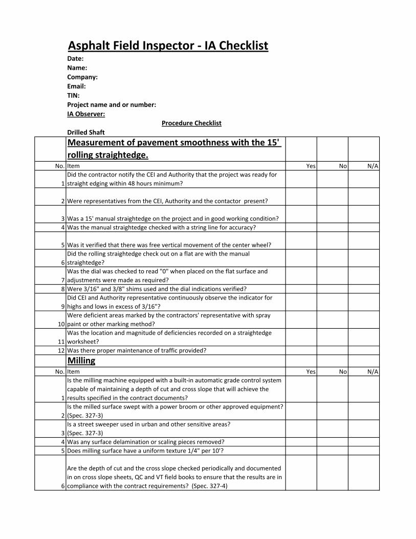
Measurement of pavement smoothness with the 15'
rolling straightedge.No. Item Yes No N/A
1
Did the contractor notify the CEI and Authority that the project was ready for
straight edging within 48 hours minimum?
2 Were representatives from the CEI, Authority and the contactor present?
3 Was a 15' manual straightedge on the project and in good working condition?
4 Was the manual straightedge checked with a string line for accuracy?
5 Was it verified that there was free vertical movement of the center wheel?
6
Did the rolling straightedge check out on a flat are with the manual
straightedge?
7
Was the dial was checked to read "0" when placed on the flat surface and
adjustments were made as required?
8 Were 3/16" and 3/8" shims used and the dial indications verified?
9
Did CEI and Authority representative continuously observe the indicator for
highs and lows in excess of 3/16"?
10
Were deficient areas marked by the contractors' representative with spray
paint or other marking method?
11
Was the location and magnitude of deficiencies recorded on a straightedge
worksheet?
12 Was there proper maintenance of traffic provided?
MillingNo. Item Yes No N/A
1
Is the milling machine equipped with a built-in automatic grade control system
capable of maintaining a depth of cut and cross slope that will achieve the
results specified in the contract documents?
2
Is the milled surface swept with a power broom or other approved equipment?
(Spec. 327-3)
3
Is a street sweeper used in urban and other sensitive areas?
(Spec. 327-3)
4 Was any surface delamination or scaling pieces removed?
5 Does milling surface have a uniform texture 1/4" per 10'?
6
Are the depth of cut and the cross slope checked periodically and documented
in on cross slope sheets, QC and VT field books to ensure that the results are in
compliance with the contract requirements? (Spec. 327-4)
Procedure Checklist
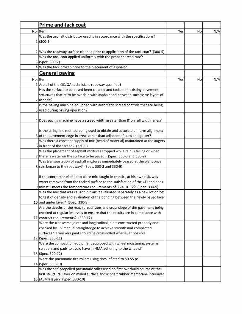
Prime and tack coatNo. Item Yes No N/A
1
Was the asphalt distributor used is in accordance with the specifications?
(300-3)
2 Was the roadway surface cleaned prior to application of the tack coat? (300-5)
3
Was the tack coat applied uniformly with the proper spread rate?
(Spec. 300-7)
4 Was the tack broken prior to the placement of asphalt?
General pavingNo. Item Yes No N/A
1 Are all of the QC/QA technicians roadway qualified?
2
Has the surface to be paved been cleaned and tacked on existing pavement
structures that re to be overlaid with asphalt and between successive layers of
asphalt?
3
Is the paving machine equipped with automatic screed controls that are being
used during paving operation?
4 Does paving machine have a screed width greater than 8' on full width lanes?
5
Is the string line method being used to obtain and accurate uniform alignment
of the pavement edge in areas other than adjacent of curb and gutter?
6
Was there a constant supply of mix (head of material) maintained at the augers
in front of the screed? (330-9)
7
Was the placement of asphalt mixtures stopped while rain is falling or when
there is water on the surface to be paved? (Spec. 330-3 and 330-9)
8
Was transportation of asphalt mixtures immediately ceased at the plant once
rain began to the roadway? (Spec. 330-3 and 330-9)
9
If the contractor elected to place mix caught in transit , at his own risk, was
water removed from the tacked surface to the satisfaction of the CEI and does
mix still meets the temperature requirements of 330-10.1.2? (Spec. 330-9)
10
Was the mix that was caught in transit evaluated separately as a new lot or lots
to test of density and evaluation of the bonding between the newly paved layer
and under layer? (Spec. 330-9)
11
Are the depths of the mat, spread rates and cross slope of the pavement being
checked at regular intervals to ensure that the results are in compliance with
contract requirements? (330-12)
12
Were the transverse joints and longitudinal joints constructed properly and
checked by 15' manual straightedge to achieve smooth and compacted
surfaces? Transvers joint should be cross-rolled whenever possible.
(Spec. 330-11)
13
Were the compaction equipment equipped with wheel moistening systems,
scrapers and pads to avoid have in HMA adhering to the wheels?
(Spec. 320-12)
14
Were the pneumatic-tire rollers using tires inflated to 50-55 psi.
(Spec. 330-10)
15
Was the self-propelled pneumatic roller used on first overbuild course or the
first structural layer on milled surface and asphalt rubber membrane interlayer
(AEMI) layer? (Spec. 330-10)
16
Was the last structural layer protected prior to the friction course, newly
finished dense-graded friction course and traffic until the surface temperature
of the layers cooled below 106 degrees F? (Spec. 330-13)
17
Was acceptance testing with a minimum of one of pass with a calibrated
standard 15' rolling straightedge operated along the centerline of each lane
tested? (Spec. 330-12)
18
Did the lift thickness meet the specification requirements?
(Spec. 334-1)
19
Contracts not using the QC-2000 specs which are Superpave projects, did the
trial section/test strip meet the constructed new design mixes in compliance
with the contract requirements? (Spec. 334-4)
20
Were the cores for acceptance laid out by the Engineer in accordance with a
random number chart in longitudinal direction?
21
Were the location of the cores checked transversely spaced uniformly across
the width of pavement with no cores located less than 1' to any unsupported
edge?
Asphalt Rubber Membrane Interlayer (ARMI)No. Item Yes No N/A
1
Did the application rate of the asphalt rubber binder and the cover material
meet the specification requirements? (Spec. 341-5)
2
Did the rolling operation of the ARMI layer conform to the contract
documents? (Spec. 341-6)
3
Was ARMI layer covered with the first course of asphalt concrete prior to being
opened to traffic? (Spec. 341-8)
4
Was the viscosity of the asphalt rubber binder checked in accordance with the
required frequency and recorded on the daily asphalt reports? (Spec. 336-5)
Friction CourseNo. Item Yes No N/A
1
Does the mix delivered to roadway meet the design criteria and approved by
the FDOT? (FC-2/FC-3 - Spec. 337-2, 337-3, 337-4)
(FC 5 - Spec. 337A-2, 337A-3, 337A-4)
2
Was the temperature of the mixture and the air temperature at lay down meet
the specification requirements? (Spec. 337-7 and 337A-7)
3
Is the spread rate of the friction course is checked every 5 loads?
(Spec. 337-7 and 337A-7)
4
Was it verified that the roller does not crush the aggregate of the friction
course during compaction operations? (337-7 and 337A-7)
Notes:
Concrete Field Inspector - IA ChecklistDate:
Technician's Name:
Technician's Company:
TIN:
Project name and or number:
IA Observer:
ASTM C 172 Sampling Freshly Mixed ConcreteNo. Item Pass Fail
1 Obtain a representative sample (i.e., form a revolving drum truck mixer).
2
Sample the concrete at two of more regularly spaced intervals during discharge
of the middle portion of the batch.
3
Repeatedly pass receptacle through entire discharge stream or completely
divert discharge stream into sampling container.
4 Transport samples to place of testing.
5 Combine samples and remix to form composite sample.
6
Obtaining the first and final portion of the composite sample shall not exceed
15 minutes.
7 Minimum size of sample used for strength tests shall be 1 cubic ft.
8
Start tests for slump, temperature, and air within 5 minutes after obtaining final
portion of composite sample.
9
Start molding cylinders within 15 minutes after fabricating the composite
sample.
10 Protect sample against rapid evaporation and contamination.
ASTM C 1064 Temperature of Freshly mixed Portland Cement ConcreteNo. Item Pass Fail
1 Place thermometer in sample with a minimum of 3". cover around sensor.
2 Close the air void by gently pressing the concrete around the measuring device
3
Read the temperature after a minimum period of 2 minutes but no more than 5
minutes.
4 Do not remove the device from the concrete when reading the temperature.
5 Record the measured temperature to the nearest 1°F.
ASTM C 143 Slump of Hydraulic ConcreteNo. Item Pass Fail
1 Obtain a sample of freshly mixed concrete per ASTM C 172.
2 Dampen the mold and the floor or base plate.
3
Hold the mold firmly against the base by standing on two foot pieces. Do not
allow it to move in any way during filing and perimeter cleaning.
4
Fill mold in three approximately equal layers (by volume), the first to a depth of
2-5/8", the second to a depth of 6-1/8" and the third to just over the top of the
mold.
Procedure Checklist
5
Rod each layer throughout its depth 25 times, distributing the strokes uniformly
over the cross section of each layer.
6
Rod the second and third layers penetrating into the underlying layer
approximately 1".
7 When rodding the top layer, keep excess concrete above the mold at all times.
8 Strike off concrete level with top of mold using the tamping rod.
9 Remove concrete from the area surrounding base of the mold.
10
Lift the mold upward 12" on one smooth motion, without twisting the mold, in
5+/- 2 seconds
11
Immediately measure to the nearest 1/4" the slump from the top of mold to the
displaced original center of the top surface of the specimen
12 Perform the test from start to finish within 2-1/2 minutes.
ASTM C 231 Air Content of Freshly Mixed Concrete by Pressure MethodNo. Item Pass Fail
1 Select a representative sample.
2
Dampen container and fill in three equal layers by moving scoop around
perimeter when filling, slightly overfilling the last layer.
3
Rod each layer 25 times with hemispherical end of rod uniformly distributing,
uniformly distributing strokes..
4
Rod bottom layer throughout its depth without forcibly striking bottom of
container.
5
Rod the middle and top layer throughout their depths and penetrating about 1"
into the underlying layer.
6
Tap the sides of the container smartly 10-15 times with the mallet after rodding
each layer.
7
Strike off concrete (using a sawing motion) level with top of container using the
bar clean off rim..
8 Clean and moisten inside of cover before clamping to base.
9
Is the aggregate correction factor records determined on the actual concrete
proportions being tested.
10 Open both petcocks.
11 Close air valve between air chamber and the bowl.
12 Inject water through petcock until it flows out the other petcock.
13
Continue injecting water into the petcock while jarring and tapping the meter to
insure all air is expelled.
14 Close air bleeder valve and pump air up to initial pressure line.
15 Allow a few seconds for the compressed air to stabilize.
16 Adjust the gauge to the initial pressure.
17 Close both petcocks.
18 Open air valve between chamber and bowl.
19 Tap sides of bowl smartly with mallet.
20
Read the air percentage after lightly tapping the gauge to stabilize the gauge
hand.
Type B METER
21
Release main air valve and the open petcocks to release pressure before
removing the cover.
22
Calculate air content correctly Air= (meter reading) - (Aggregate correction
factor) nearest 0.1%.
23
If gauge reading of the meter exceeds 8%, in which case the corrected reading
shall be reported to the nearest 1/2 scale division on the dial.
ASTM C 31 Making Curing Concrete Test Specimens in the FieldNo. Item Pass Fail
1 Place molds on a level, rigid, horizontal surface free of vibration.
2 Select a representative sample in accordance with ASTM C 172.
3
Place concrete in the mold, moving the proper size placement tool around top
edge of the mold as the concrete is discharged without spillage.
4
For 6" x 12" cylinders: Fill mold in three layers of equal volume.
For 4" x 8" cylinders: Fill mold in two layers of equal volume.
5
For 6" x 12" cylinders: Rod each layer 25 times with rounded end of rod,
uniformly distributing strokes. For
4 x 8 in. cylinders: Rod each layer 25 times with rounded end of rod, uniformly
distributing strokes.
6
Rod bottom layer throughout its depth. Rod the middle (if applicable) and top
layers to a depth of 1" into the underlying layers.
7
Tap the sides of the mold lightly 10-15 times with a mallet, or open hand (Light-
gauge, single-use molds only), after rodding each layers.
8
On the final layer, add an amount that will fill the mold after consolidation.
Adjust under filled or overfilled molds with representative concrete and
complete the required strokes.
9
Strike off excess concrete from the surface with a tamping rod, float or trowel as
required. Use the minimum amount of manipulation necessary to produce a
flat, even surface.
10
Mark specimens with positive identification, not on removable caps, using a
method that does not alter the top surface of the concrete.
11
Initial curing - Immediately after molding specimen stored for a period up to 48
hours range of 60-80° F. Record the temperature using a maximum/minimum
thermometer.
12 Shield all specimens from direct sunlight.
Notes:
Drilled Shaft Inspector - IA ChecklistDate:
Name:
Company:
TIN:
Project name and or number:
IA Observer:
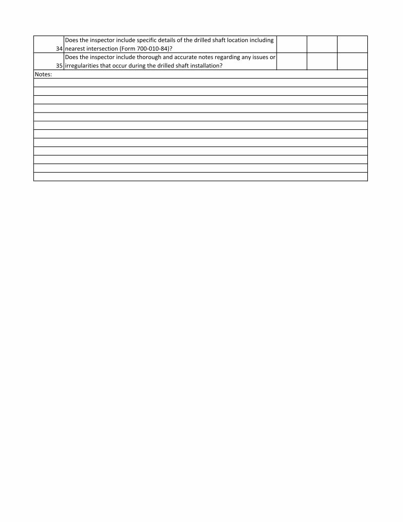
Drilled Shaft No. Item Yes No N/A
1
Does the inspector have the necessary Personal Protective Equipment (PPE) -
including hard hat, safety vest, etc.?
2
Does the inspector have a copy of the project's drilled shaft plans (including soil
borings)?
3
Does the inspector have a copy of the applicable FDOT Road and Bridge Specs,
Standard Design Index and Supplemental Specifications for the project?
4Does the inspector have a copy of the DSIP and mix design? (spec
455-15.1.2 and 455-17.1)
5
Does the inspector have the required tools, equipment and forms to inspect
and document the drilled shaft installations? (ex. drilled shaft


![[PPT]PowerPoint Presentation - University of Delaware 486/Earthwork Notes.ppt · Web viewConstruction Methods & Management CIEG 486-010 Earthwork Earthwork Earthwork Earthwork Earthwork](https://static.documents.pub/doc/80x56/5ab3861f7f8b9ad9788e28f7/pptpowerpoint-presentation-university-of-486earthwork-notespptweb-viewconstruction.jpg)


