This document has been prepared by ARTC for internal use and may not be relied on by any other party without ARTC’s prior wri tten consent. Use of this document shall be subject
to the terms of the relevant contract with ARTC.
ARTC and its employees shall have no liability to unauthorised users of the information for any loss, damage, cost or expense incurred or arising by reason of an unauthorised user
using or relying upon the information in this document, whether caused by error, negligence, omission or misrepresentation in this document.
This document is uncontrolled when printed.
Authorised users of this document should visit ARTC’s intranet or extranet (www.artc.com.au) to access the latest version of this document.
Page 1 of 98
Earthworks Construction
Specification
ETC-08-04
Applicability
NSW QLD VIC SMS
Publication Requirement
Internal / External
Primary Source
0-9000-PEN-00-SP-1001
Document Status
Version # Date Reviewed Prepared by Reviewed by Endorsed Approved
1.1 25 Sep 2019 System and
Procedure
Administrator
Standards Manager
Standards
General Manager
Technical Standards
02/10/2019
Amendment Record
Amendment
Version #
Date Reviewed Clause Description of Amendment
1.0 23 Nov 2017 First Issue
1.1 25 Sep 2019 1.5 & App B Removal of Confidential from title page, Procedure Owner
section added and ‘To be Issued’ statement to Appendix B
This document is uncontrolled when printed. Version Number:1.1 Date Reviewed: 25 Sep 2019 Page 2 of 98
Table of Contents
Table of Contents ............................................................................................................................................. 2
List of Figures ................................................................................................................................................... 7
List of Tables ..................................................................................................................................................... 7
1 Scope and Purpose ................................................................................................................................ 8
3 Codes and Standards .......................................................................................................................... 17
4 General .................................................................................................................................................. 18
5.11.1 Stockpile Areas ............................................................................................................................. 28
6 Foundation Treatments ....................................................................................................................... 33
6.1 General ......................................................................................................................................... 33
6.5.1 Type T3 – Terracing ..................................................................................................................... 42
7 Excavation of Cuttings ........................................................................................................................ 43
7.1 General ......................................................................................................................................... 43
7.2 Non-Rippable Material ................................................................................................................. 43
8.1 General ......................................................................................................................................... 52
8.2 Earth Fill Embankments ............................................................................................................... 52
8.2.1 Earth Fill Material .......................................................................................................................... 52
8.2.2 Earth Fill Placement and Compaction........................................................................................... 53
8.3 Rock Fill Embankments ............................................................................................................... 53
8.3.1 Rock Fill Material .......................................................................................................................... 53
8.3.2 Rock Fill Placement and Compaction ........................................................................................... 54
8.3.3 Surplus Rock Fill Material ............................................................................................................. 54
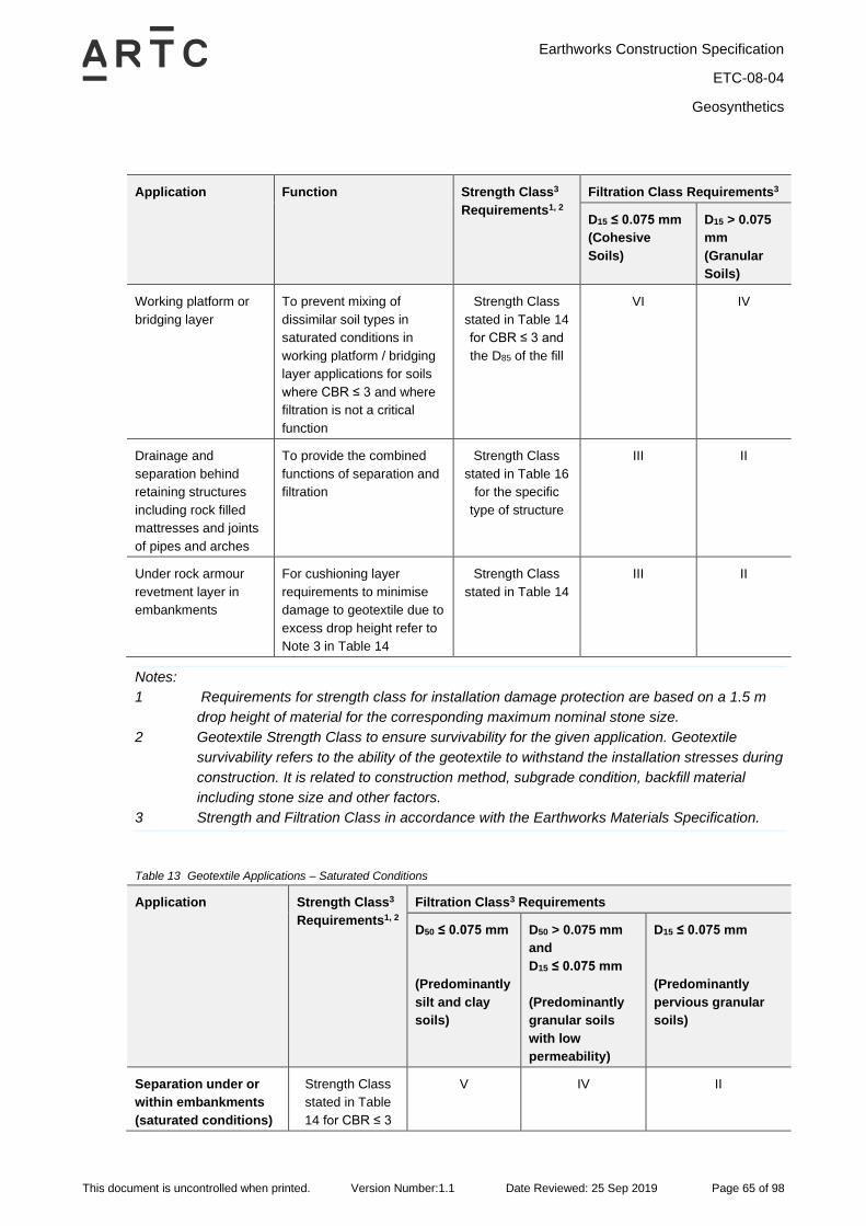
11.1 General ......................................................................................................................................... 64
12.1 General ......................................................................................................................................... 70
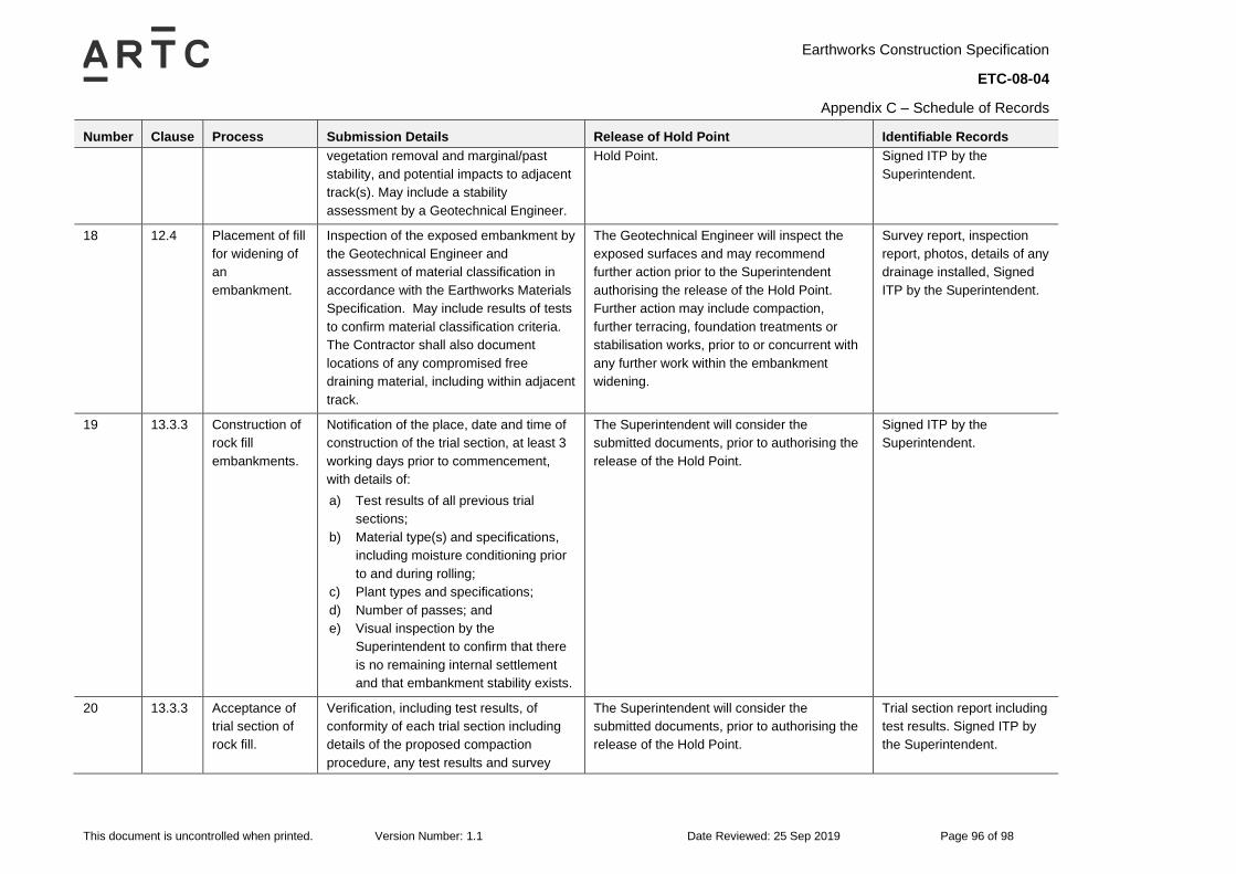
12.4 Construction of Widened Embankment ....................................................................................... 71
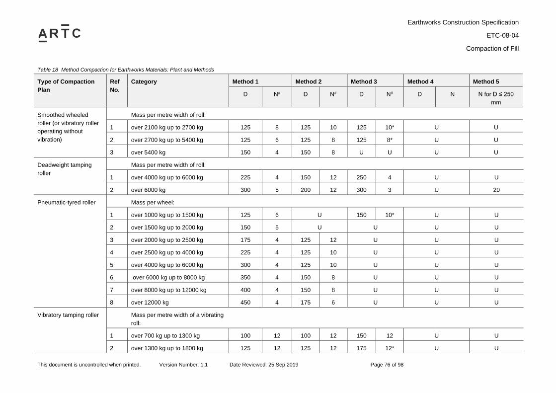
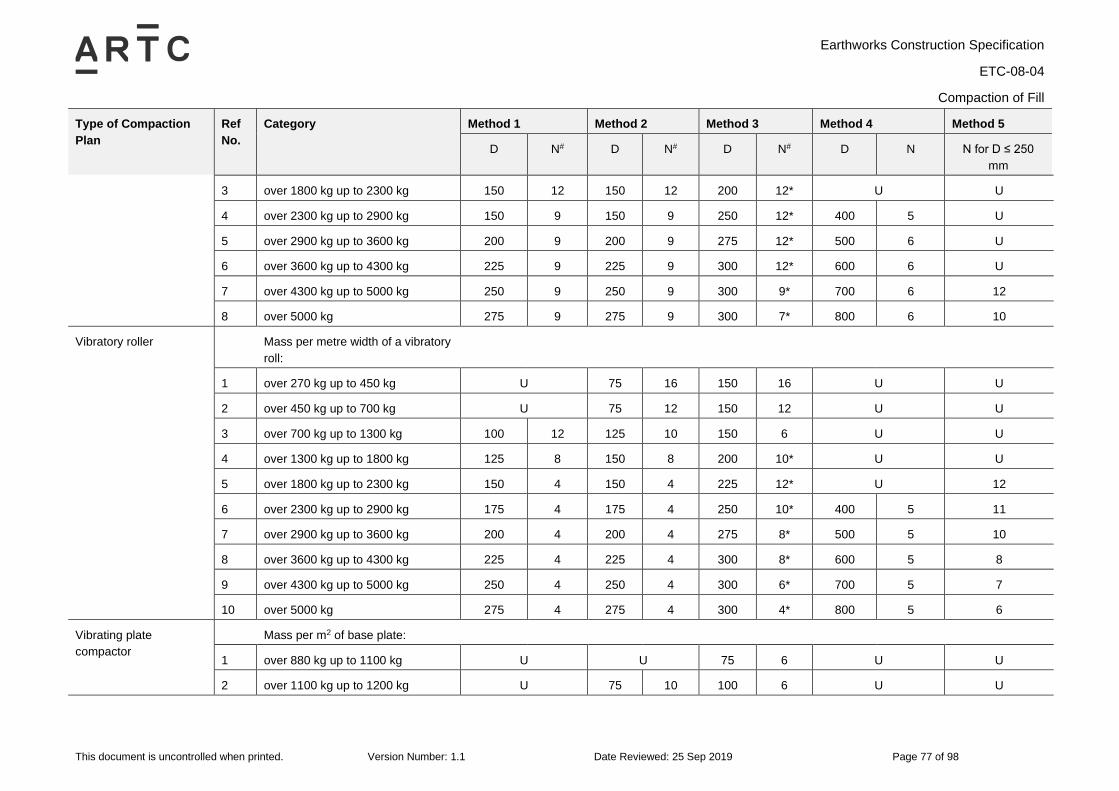
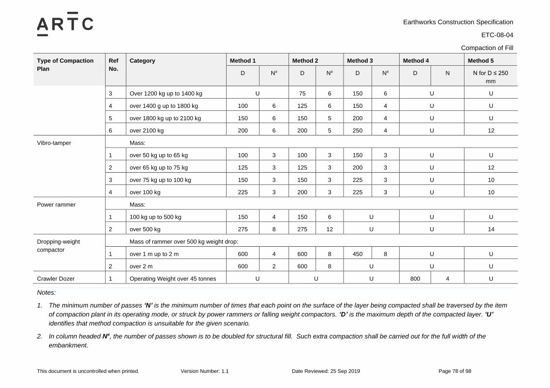
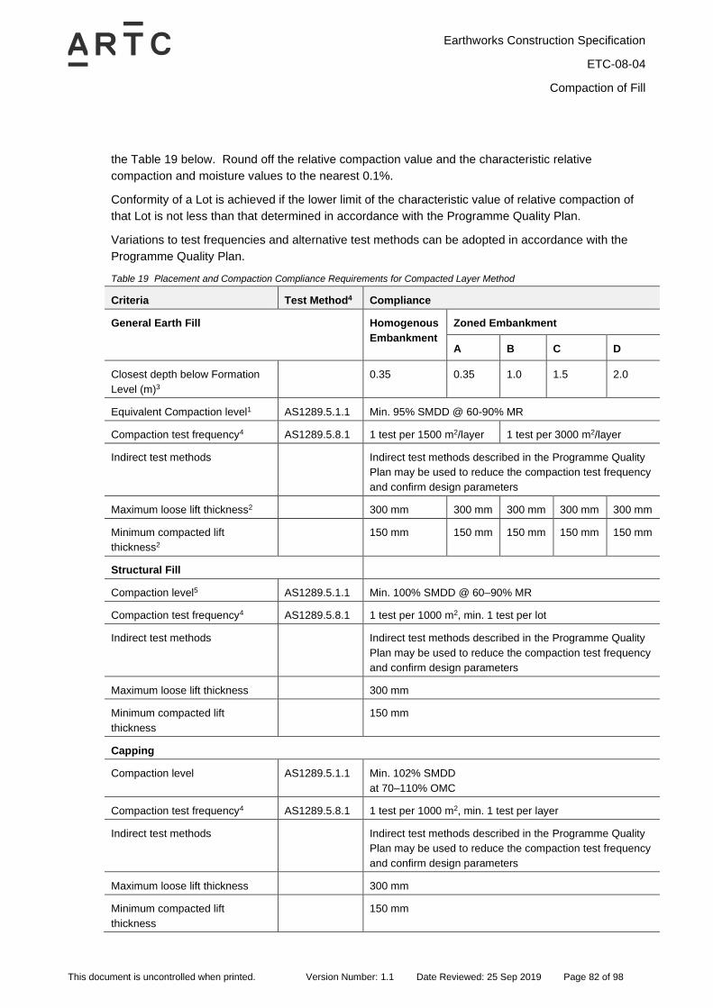
13 Compaction of Fill ................................................................................................................................ 73
13.1 General ......................................................................................................................................... 73
This document is uncontrolled when printed. Version Number:1.1 Date Reviewed: 25 Sep 2019 Page 6 of 98
13.4.2 Alternative Test Frequencies and Methods .................................................................................. 83
13.5 Proof Rolling ................................................................................................................................. 84
13.6 Inspection and Test Plans ............................................................................................................ 85
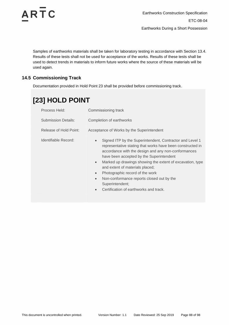
14 Earthworks During a Short Possession ............................................................................................. 86
14.1 General ......................................................................................................................................... 86
14.2 Roles and Responsibilities ........................................................................................................... 86
This document is uncontrolled when printed. Version Number:1.1 Date Reviewed: 25 Sep 2019 Page 18 of 98
4 General
4.1 Private Property
No private property shall be removed, relocated or altered without the approval of the Superintendent.
4.2 Services
All work areas are to be subject to a complete services search. The search is to identify all internal
(rail operator) and external (public utilities) services associated with the Works.
All services are to be identified on a plan provided by the Contractor indicating service depth and
location with respect to the rail corridor. All services to be clearly marked on site and appropriate
protection measures taken.
4.3 Construction Water
Construction water quality shall not compromise the design life of rail infrastructure in contact with
earthworks (including via leachates or runoff). An example is the adverse effects which can arise from
the use of water with high chloride concentrations for compaction or from the incorporation of acid
generating soils or rocks within the Works without appropriate control measures.
The Contractor is to evaluate the suitability of non-potable water by field and laboratory testing at the
discretion of and as approved by the Superintendent. This includes but is not limited to ensuring the
chemical composition of the water does not contribute to an environment exceeding any adjoining
structure’s design exposure classification as specified on the Drawings, or does not affect the
establishment of vegetation.
Earthworks Construction Specification
ETC-08-04
General Earthworks
This document is uncontrolled when printed. Version Number:1.1 Date Reviewed: 25 Sep 2019 Page 19 of 98
5 General Earthworks
5.1 Protection of Earthworks and Structures
The Contractor is responsible for the protection of earthworks and structures, specifically:
• Installation and maintenance of effective erosion and sedimentation control measures in
accordance with the Programme Environmental Management Plan.
• Provision and maintenance of measures for drainage of the working areas without scouring from
the surface run-off. Do not allow water to pond in the working areas resulting in wetting up of the
existing pavement, formation or foundation material, except where ponding is off the formation and
forms part of a planned erosion and sedimentation control system.
• Taking all precautions to minimise any ingress of water into the earthworks material including
shaping to avoid ponding. When rain is likely, or when no work is planned for the following day in a
particular area being worked, seal off ripped material remaining in the floor of cuttings and material
placed on embankments, using a smooth drum roller.
• Should earthworks material become over-wet (above the specified moisture content for
compaction), replace or dry out the material.
• Do not allow earthworks material in embankments to dry out to the point where excessive
shrinkage occurs, and the surface is pulverised by traffic generating excessive dust.
• No excavation shall be undertaken which effects the stability or integrity of any structure (e.g.
overbridges and retaining walls) without prior approval by the Superintendent.
• Permanent erosion and sediment controls such as topsoiling, grassing or hydroseeding and
hydromulching or other controls shall be carried out as specified at the earliest practicable date.
• Temporary and permanent works shall be limited to safe heights and slopes. Excavation shall be
carried out in such a manner and sequence so as to prevent erosion or slips, working faces shall
be limited to safe heights and slopes, and provide proper drainage at all times to avoid ponding
and erosions.
The Contractor is responsible for all cost and time delays associated with the repairs to damaged
earthworks resulting from failure to comply with the requirements outlined above.
5.2 Access to the New Foundation and New Formation
If the Contractor requires access to a part of the Site where no access has been provided, the
Contractor shall supply to the Superintendent all plans for obtaining such access and shall not
commence work on the access until approval has been given.
The completed formation shall be used as an access road only where approved by the
Superintendent. Where approved, it shall be used in such a manner to afford minimum damage to the
capping layer, formation, ditches, shoulders and slopes. Construction traffic on new and reconstructed
formations shall be managed such that uniformity of compaction parallel and perpendicular to the
tracks is maintained. All repairs required to restore the capping material or the formation to its original
condition shall be at the Contractor’s expense.
Earthworks Construction Specification
ETC-08-04
General Earthworks
This document is uncontrolled when printed. Version Number:1.1 Date Reviewed: 25 Sep 2019 Page 20 of 98
No additional payment will be made to the Contractor for provision of additional roads or the upgrading
of existing access roads.
Transportation and distribution of materials and construction shall be suspended if, in the opinion of
the Superintendent, the formation is too wet to enable work to proceed.
5.3 Permanent Erosion and Scour Protection
Permanent erosion and scour protection shall be provided in accordance with the Drawings and be
constructed in a progressive manner over the course of the Works, thus minimising the use of
temporary works where possible.
5.4 Drainage of Works
During construction the Contractor shall provide for the effective diversion of surface water from the
Works. These requirements shall apply equally to off-site construction including access roads and
borrow area and stockpiles.
The Contractor shall provide efficient pumping equipment on site and shall keep trenches and
excavations dewatered at all times during construction.
At all times during construction, water is not permitted to pond on or adjacent to an embankment
unless stated otherwise on the Drawings or authorised by the Superintendent. At the close of work
each day, the surface of the embankment shall be left free draining.
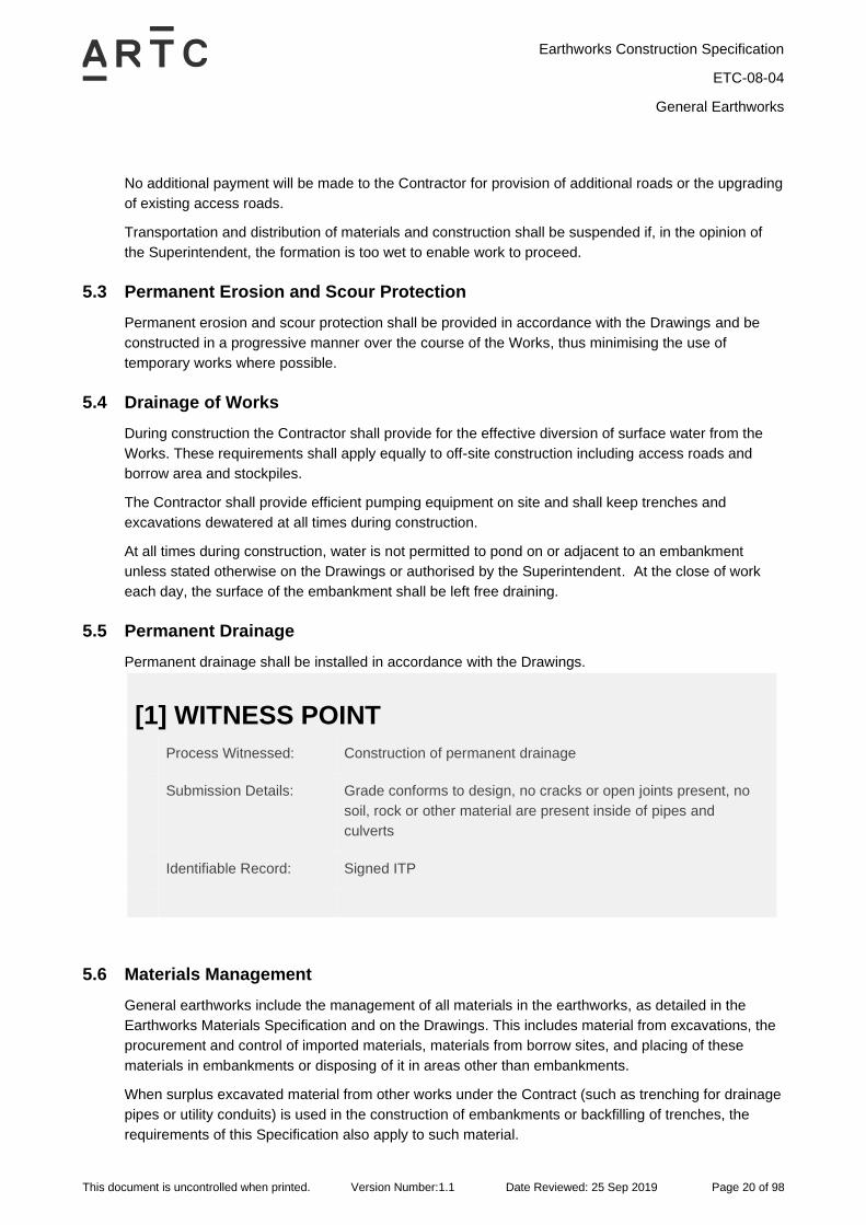
5.5 Permanent Drainage
Permanent drainage shall be installed in accordance with the Drawings.
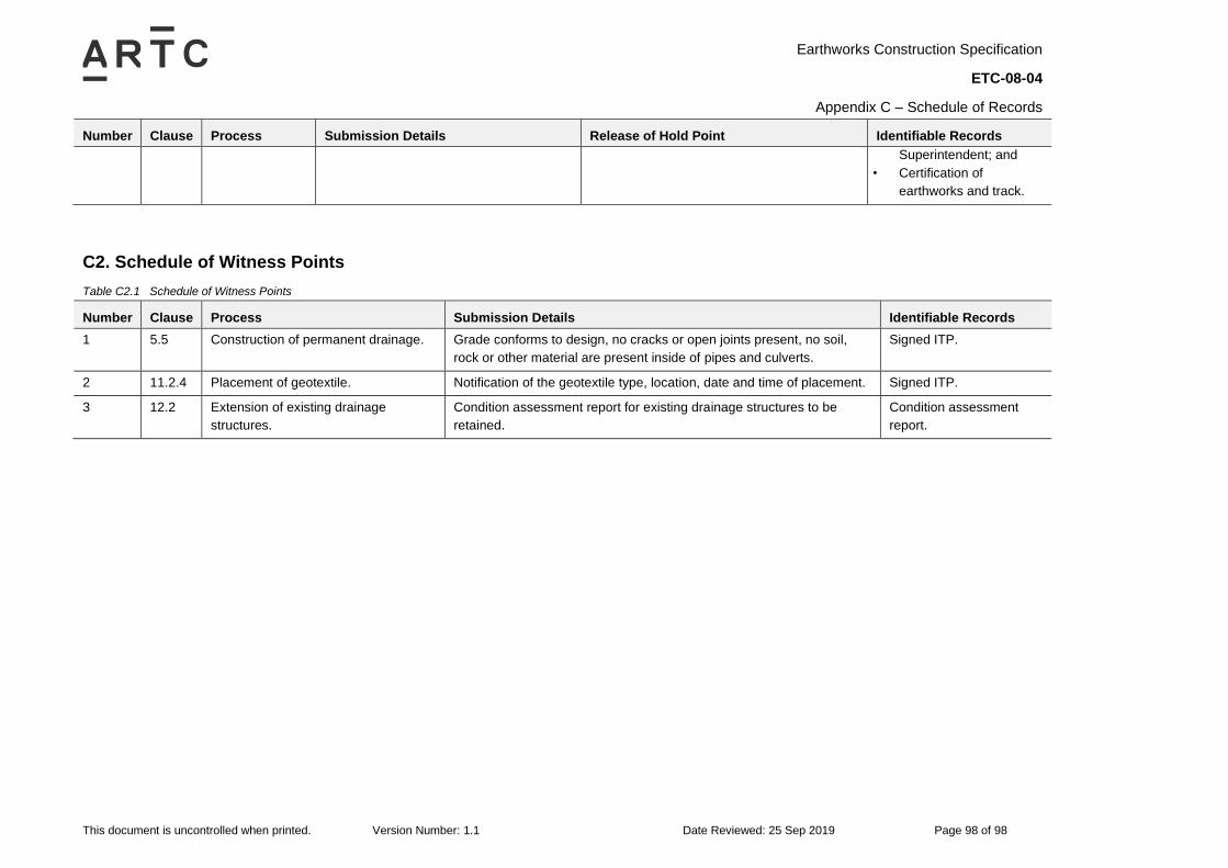
[1] WITNESS POINT
Process Witnessed: Construction of permanent drainage
Submission Details: Grade conforms to design, no cracks or open joints present, no
soil, rock or other material are present inside of pipes and
culverts
Identifiable Record: Signed ITP
5.6 Materials Management
General earthworks include the management of all materials in the earthworks, as detailed in the
Earthworks Materials Specification and on the Drawings. This includes material from excavations, the
procurement and control of imported materials, materials from borrow sites, and placing of these
materials in embankments or disposing of it in areas other than embankments.
When surplus excavated material from other works under the Contract (such as trenching for drainage
pipes or utility conduits) is used in the construction of embankments or backfilling of trenches, the
requirements of this Specification also apply to such material.
Earthworks Construction Specification
ETC-08-04
General Earthworks
This document is uncontrolled when printed. Version Number:1.1 Date Reviewed: 25 Sep 2019 Page 21 of 98
The Contractor is responsible for:
• Any assumptions made in relation to the nature and types of the materials (meeting requirements
of the Earthworks Materials Specification) as encountered in excavations or imported, and the
bulking and compaction characteristics of all such materials which are then incorporated in the
Works;
• Determining suitable sources of material and any processing needed to satisfy the requirements of
the Earthworks Materials Specification;
• The design, and the cost of construction and maintenance of all tracks, roads, haul roads, pads
and other earthworks structures required for the proper execution of the Works;
• The Contractor shall adjust the method of working and programme of work such that sufficient
hard and durable rock scour protection, as per Section 8.5, is available when required;
• Managing procurement of materials to ensure sufficiency of materials of the specified quality; and
• Achieving a high utilisation of structural fill and capping material from excavations, unless
otherwise proven uneconomical.
If the Contractor causes a deficiency of fill material by electing not to use acceptable material from
excavations in the embankments and formation or by constructing embankments with dimensions
other than those shown on the Drawings or authorised by the Superintendent, the Contractor must
make good that deficiency from sources of material meeting the quality requirements specified in the
Earthworks Materials Specification. The cost of making good such deficiency of material will be borne
by the Contractor.
5.7 Clearing and Grubbing
Clearing includes the removal from the site of all trees, stumps (parts above ground), logs,
boulders/rocks up to 1.0 m in size which are exposed or lying on the surface, saplings, bushes, scrub
or similar growth, levelling of obsolete terraces, ditches, windrows, minor man-made structures,
obstructions and property improvements (e.g. fences and livestock yards) and any surface feature that
is considered unsuitable for incorporation into the works.
Grubbing includes removal of the base of stumps, roots, buried logs, the underground parts of
structures and other obstructions that obtrude, encroach upon or otherwise obstruct the work and
other subsurface material considered unsuitable by the Superintendent for incorporation in the Works.
All property improvements shall be similarly removed. Should any trees or boughs lean over the
boundaries, they shall be removed.
Clearing and grubbing also includes:
• Setting aside marketable timber.
• Setting aside vegetative material suitable for processing to produce organic mulch.
• Placing fallen logs and branches suitable for fauna habitat or erosion and sediment control clear of
construction activities.
• Salvage of fences, posts, signs, structures and other obstructions that interfere with the Work, as
specified in Contract documents or as directed by the Superintendent.
• Mulching of trees and shrubs where specified.
Earthworks Construction Specification
ETC-08-04
General Earthworks
This document is uncontrolled when printed. Version Number:1.1 Date Reviewed: 25 Sep 2019 Page 22 of 98
• Promptly backfilling any holes remaining after trees and stumps have been grubbed. Backfilling is
to be with a sound material, compacted to at least the relative compaction of the adjacent existing
ground and completed in a manner which prevents infiltration and ponding of water. This shall
include topsoiling and vegetating holes where shown on the Drawings or directed by the
Superintendent.
• Disposing of all cleared and grubbed materials which are not to be reused.
No clearing and grubbing shall be done unless approved by the Superintendent. No property or
existing infrastructure (e.g. pipes, buildings, crops, signs and fences) shall be removed, relocated or
altered without the approval of the Superintendent.
[1] HOLD POINT
Process Held: Clearing and grubbing
Submission Details: a) Plans showing extent of clearing and grubbing; and
b) All the necessary approvals and consents, including
environmental approvals.
Release of Hold Point: The Superintendent will approve work prior to authorising
the release of the Hold Point.
Identifiable Record: Approved plans signed by Superintendent and Contractor
Clearing and grubbing operations shall be limited to the area shown on the Drawings.
The Contractor shall plan and carry out clearing operations to avoid erosion, contamination and
sedimentation of the site, surrounding areas, watercourses, streams and other drainage systems.
Grubbing operations shall be carried out to a minimum depth of 0.3 m below the foundation level.
Trees, shrubs, other landscape features and improvements within the limits of the Works which are
designated by the Superintendent for preservation shall not be removed or damaged and shall be
protected during the progress of the work in a manner satisfactory to the Superintendent.
The Contractor shall take all necessary precautions to ensure that natural vegetation and fauna
habitat outside the areas defined for clearing and grubbing are maintained without damage or
disfiguration for the duration of the Contract.
Grass and topsoil shall not be removed as part of clearing or grubbing works.
All damage incurred to the Principal’s property and to adjourning property during clearing operations
shall be made good by the Contractor at its own expense.
The Contractor will only be paid once for clearing and grubbing works.
Earthworks Construction Specification
ETC-08-04
General Earthworks
This document is uncontrolled when printed. Version Number:1.1 Date Reviewed: 25 Sep 2019 Page 23 of 98
[2] HOLD POINT
Process Held: All works, after completion of clearing and grubbing, which will
alter the ground surface as surveyed.
Submission Details: a) Survey Report of the existing surface levels of the section of
Works, in accordance with the Contractor’s PQP, submitted
at least 3 working days before the proposed date for altering
the surfaces.
b) For the section of Works, notification that:
i. The survey set out has been carried out,
including set out of the cut to fill intersection point
and extent of the Transition Zone as specified in
Section 6.4.
ii. Erosion and sedimentation controls have been
implemented;
iii. Clearing, grubbing and removal of cleared
materials for that section of the Works has been
completed.
Release of Hold Point: The Superintendent will inspect the surfaces and set out, and
may direct further action prior to authorising the release of the
Hold Point. Further action may include altering the limits of the
cut/fill transition.
Identifiable Record: a) Hold point release record;
b) Survey report; and
c) Approved plans signed by the Superintendent and
Contractor.
5.8 Topsoil
5.8.1 Removal of Topsoil
Removal of topsoil shall be performed to provide a stable base for the works to be constructed.
Topsoil shall be removed to a depth as shown on the Drawings or as directed by the Superintendent
and stockpiled clear of the Work. Topsoil shall not be removed in locations where a bridging layer is
to be constructed in accordance with Section 6.2.7, unless directed otherwise by the Superintendent.
Topsoil removal shall only commence in areas where earthworks are to occur within 1 week.
The Contractor shall plan and carry out removal of topsoil to avoid erosion, contamination and
sedimentation of the Site, surrounding country, watercourses and streams.
Earthworks Construction Specification
ETC-08-04
General Earthworks
This document is uncontrolled when printed. Version Number:1.1 Date Reviewed: 25 Sep 2019 Page 24 of 98
Where directed by the Superintendent, after removal of the topsoil:
• Stockpile non-contaminated topsoil in accordance with Section 5.8.2 and Section 5.11. The
Contractor is to identify if non-contaminated topsoil is suitable for planting media and where so,
stockpile separately; and
• If the topsoil has been identified as contaminated material, spoil the topsoil in accordance with
Section 5.10.3.
After removing the topsoil, the Contractor shall determine the surface levels in each cutting and
embankment at sufficient locations to determine the volume of excavation and filling for general
earthworks and the volume of Unsuitable Material.
5.8.2 Topsoil Stockpiles
Locate topsoil stockpiles in accordance with Section 5.11. Topsoil stockpiles must be located
separately to other stockpiles and clear of the Works for use in revegetation unless directed
otherwise by the Superintendent.
Before stockpiling topsoil, carry out a survey to determine the surface levels at each stockpile area,
at sufficient positions to later determine the volumes of topsoil placed at the location.
Topsoil stockpiles must:
• Be free from subsoil, other excavated materials, contaminated materials, refuse, clay lumps and
stones, timber or other rubbish.
• Unless specified otherwise on the Drawings, be trimmed to a regular shape to facilitate quantity
measurement, and with a height not exceeding 2.5 m and batter slopes not steeper than 2H:1V.
• Not be trafficked unless approved by the Superintendent.
• Have their batters track rolled or stabilised by other means approved by the Superintendent.
5.9 Unsuitable Material
5.9.1 General
It shall be the sole responsibility of the Contractor to prove that material is Unsuitable Material as
defined in the Earthworks Materials Specification. Where previously unidentified Unsuitable Material
or potentially Unsuitable Material is encountered on the Site, the Contractor shall, before proceeding
to treat such material, notify the Superintendent.
The Contractor shall carry out a survey to determine the surface levels at sufficient locations before
and after removal of all Unsuitable Material to determine the volume of Unsuitable Material removed.
Alternatively, the Superintendent may agree to determination of volume by manual measurement
(with a tape measure or other means) and calculation. The dimensions of the removal shall be
included in the Work as Executed Drawings.
Earthworks Construction Specification
ETC-08-04
General Earthworks
This document is uncontrolled when printed. Version Number:1.1 Date Reviewed: 25 Sep 2019 Page 25 of 98
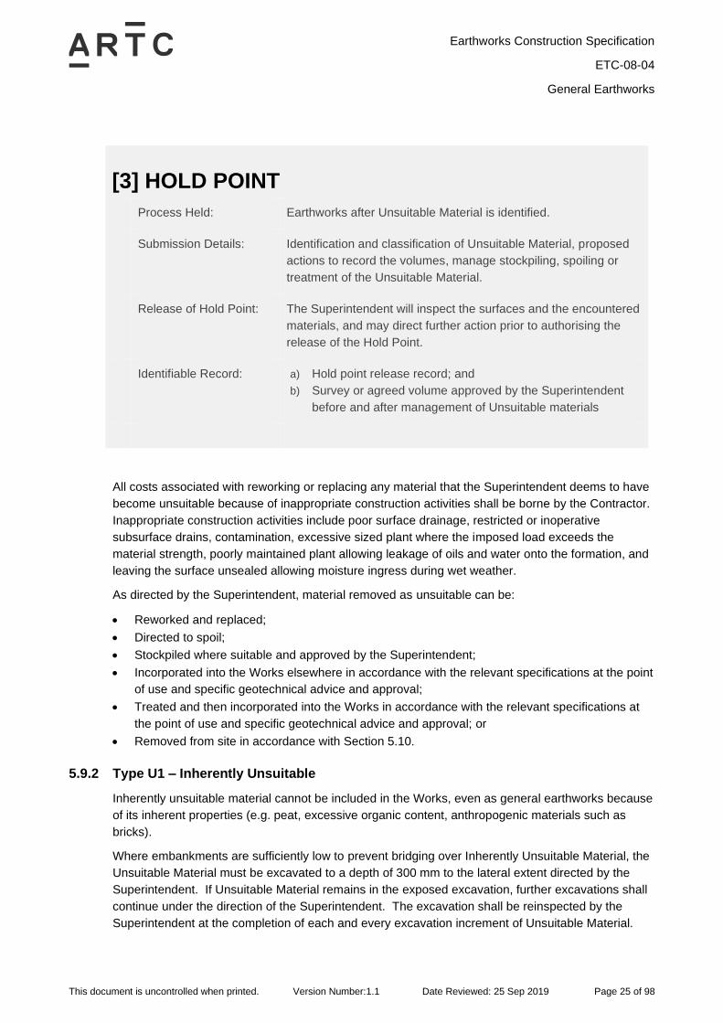
[3] HOLD POINT
Process Held: Earthworks after Unsuitable Material is identified.
Submission Details: Identification and classification of Unsuitable Material, proposed
actions to record the volumes, manage stockpiling, spoiling or
treatment of the Unsuitable Material.
Release of Hold Point: The Superintendent will inspect the surfaces and the encountered
materials, and may direct further action prior to authorising the
release of the Hold Point.
Identifiable Record: a) Hold point release record; and
b) Survey or agreed volume approved by the Superintendent
before and after management of Unsuitable materials
All costs associated with reworking or replacing any material that the Superintendent deems to have
become unsuitable because of inappropriate construction activities shall be borne by the Contractor.
Inappropriate construction activities include poor surface drainage, restricted or inoperative
subsurface drains, contamination, excessive sized plant where the imposed load exceeds the
material strength, poorly maintained plant allowing leakage of oils and water onto the formation, and
leaving the surface unsealed allowing moisture ingress during wet weather.
As directed by the Superintendent, material removed as unsuitable can be:
• Reworked and replaced;
• Directed to spoil;
• Stockpiled where suitable and approved by the Superintendent;
• Incorporated into the Works elsewhere in accordance with the relevant specifications at the point
of use and specific geotechnical advice and approval;
• Treated and then incorporated into the Works in accordance with the relevant specifications at
the point of use and specific geotechnical advice and approval; or
• Removed from site in accordance with Section 5.10.
5.9.2 Type U1 – Inherently Unsuitable
Inherently unsuitable material cannot be included in the Works, even as general earthworks because
of its inherent properties (e.g. peat, excessive organic content, anthropogenic materials such as
bricks).
Where embankments are sufficiently low to prevent bridging over Inherently Unsuitable Material, the
Unsuitable Material must be excavated to a depth of 300 mm to the lateral extent directed by the
Superintendent. If Unsuitable Material remains in the exposed excavation, further excavations shall
continue under the direction of the Superintendent. The excavation shall be reinspected by the
Superintendent at the completion of each and every excavation increment of Unsuitable Material.
Earthworks Construction Specification
ETC-08-04
General Earthworks
This document is uncontrolled when printed. Version Number:1.1 Date Reviewed: 25 Sep 2019 Page 26 of 98
The excavation shall be backfilled with fill compatible with the formation design, and in compliance
with the Earthworks Materials Specification.
All excavated Unsuitable Material shall be disposed of to spoil, in a designated area off site
determined by the Contractor and approved by the Superintendent.
Inherently Unsuitable Material may be bridged in accordance with Treatment Type E6 of Section 6.2
where shown on the Drawings.
5.9.3 Type U2 – Unsuitable by Virtue of Position
Unsuitable Material by Virtue of Position are defined in the Earthworks Materials Specification.
These materials shall be treated in accordance with Section 6 of this Specification.
5.9.4 Type U3 – Unsuitable by Moisture Content
If the Superintendent considers that the Contractor has not protected the material and the material is
unsuitable only because of its high or low moisture content, the Superintendent may direct that the
material be dried out or moisture conditioned and incorporated in the works. No additional payment
will be made for the drying out or moisture conditioning of the material (see Section 5.1). If the
Contractor allows any material to become unsuitable because of Contractors inappropriate
construction activities, all costs associated with reworking or replacing such Unsuitable Material must
be borne by the Contractor. Examples of inappropriate construction activities include poor surface
drainage, restricted or inoperative subsurface drains, contamination, excessive sized construction
plant where the imposed load exceeds the material strength, poorly maintained construction plant
allowing leakage of oils and water onto the formation, and leaving the surface unsealed allowing
moisture ingress during wet weather.
The Contractor shall promptly notify the Superintendent of all areas of the foundation and all layers
within the subgrade that ruts excessively, yield or show signs of distress or instability.
All Unsuitable Material by Moisture Content is to be left on site unless directed otherwise by the
Superintendent. Where there are materials that cannot be treated and re-used within the Works or
stockpiled on the site, such material is to be disposed of in accordance with Section 5.10 of this
Specification.
5.10 Disposal of Spoil
5.10.1 General
All excess materials removed during the course of construction shall be disposed or stockpiled as
specified by the Superintendent.
While handling and disposing of spoil, the Contractor must:
• Not end tip spoil down embankment batters.
• Schedule its operations so as to minimise haulage distances and to dispose of spoil at the
closest location.
• Sort and separate excavated material on site for use in the permanent works, unless otherwise
stated in the Contract.
• Dispose of excavated material, which in the opinion of the Superintendent cannot be selected,
processed or mixed in a practical manner to make it suitable for use in the permanent works,
unless otherwise stated in the Contract.
Earthworks Construction Specification
ETC-08-04
General Earthworks
This document is uncontrolled when printed. Version Number:1.1 Date Reviewed: 25 Sep 2019 Page 27 of 98
• Dispose of all inherently unsuitable and perishable materials off-site at a facility approved by the
Superintendent.
Before spoiling commences, the Superintendent may direct a survey, at sufficient locations, so as to
determine the surface levels at each spoil site to later determine the volumes of material spoiled.
5.10.2 Non-contaminated Materials
Non-contaminated spoil generated from the Work under the Contract shall be disposed of in the
manner and at locations authorised or agreed to by the Superintendent. The Contractor shall use up
all available areas within the Site before proposing alternative locations.
Disposal of non-contaminated material shall be by the following means, in order of preference:
1) Targeted embankment widenings to create hardstands at the end of cuttings or other appropriate
locations.
2) Uniform widening of embankments.
3) Flatter batter slopes being provided on embankments.
4) Uniform filling of selected areas within the rail corridor.
5) Stockpiling within the Site.
6) Disposal at an approved off site location.
Embankment widening or batter flattening work is deemed to form part of the embankment
construction and must be carried out in accordance with Section 12. Spoil placed in embankments
shall be classified, spread and compacted in accordance with Section 13 of this Specification and
the Earthworks Materials Specification for materials in zoned embankments. The Contractor shall
maintain effective drainage for the whole of the embankment.
If the Contractor proposes to use spoil locations outside the Site, the Contractor must obtain all the
necessary approvals and consents, including environmental approvals, and provide copies of them
to the Superintendent at least 5 working days prior to commencing the disposal of material at these
off site locations.
Payment for disposal of spoil comprising non-contaminated material within the Site is deemed to be
included in the earthworks rates.
5.10.3 Contaminated Materials
Spoil materials that meet the contaminant concentration criteria which confirms suitability for reuse
or application within commercial / industrial land use criteria, as specified within all Statutory
Requirements and the National Environment Protection (Assessment of Site Contamination)
Measure Amendment 2013 (NEPM 2013), must be beneficially reused or managed within the rail
corridor (e.g. fill, capping, ballast or other beneficial reuse) where risks to human health and the
environment can be mitigated and where feasible. This reuse shall be undertaken in accordance with
all state and federal legislative requirements, limits contamination of non-contaminated material, and
as authorised or agreed to by the Superintendent and the Principal.
Where spoil materials are found to be contaminated at levels that are unsuitable for reuse within a
commercial/industrial land use scenario as specified in all Statutory Requirements and by the NEPM
2013, the management of the materials must be undertaken to ensure that risk of harm to human
health and the environment is mitigated, and in accordance with all applicable ARTC property
Earthworks Construction Specification
ETC-08-04
General Earthworks
This document is uncontrolled when printed. Version Number:1.1 Date Reviewed: 25 Sep 2019 Page 28 of 98
leasing obligation and state and federal legislative requirements. Should management onsite be
proposed, approval from the Principal must be obtained. All management of contaminated material
must be done in accordance with the relevant state legislation and approvals/permits in place.
If management or disposal methods for spoil materials and sites are not specified, it is the
Contractor’s responsibility to determine the method(s) and location(s) for management and disposal
of the contaminated material and obtain approval from the Superintendent, the Principal’s
contamination guidelines and the relevant regulatory authorities.
The Contractor shall notify the Superintendent at least one (1) month prior to excavation of all
material that is contaminated at levels posing a risk of harm to human health or the environment, and
removal of all contaminated material from the Site, and provide details of the contaminant sampling
and assessment performed and the proposed method and location of management, remediation and
disposal.
Sampling and assessment, management, treatment and disposal of all material that is contaminated
in any way by the Contractors operations will be borne by the Contractor.
5.11 Stockpiles
5.11.1 Stockpile Areas
The Contractor shall locate stockpiles at the areas nominated in the Drawings or Specifications such
that they do not adversely impact the track and formation, drainage, sight distances, the surrounding
environment, existing infrastructure, utilities and operational access, while where applicable,
minimising the need to cross existing track during construction.
Where no such areas are nominated, or if the Contractor proposes to locate their stockpiles in areas
other than those nominated, a proposal is to be submitted with details of the maximum dimensions of
the proposed stockpiles, for approval by the Superintendent at least 10 working days before
stockpiling is due to commence. The Contractor shall obtain all the necessary approvals and
consents, including environmental approvals, and provide copies of them to the Superintendent.
Stockpiles shall be physically separated from engineered fills to prevent future misidentification of
engineered fill.
Stockpile sites in Private Property shall be restored following completion of the Works in accordance
with land owner agreements and to the satisfaction of the Superintendent.
5.11.2 Stockpile Management
Materials assigned to be stockpiled shall be segregated, stored separately and protected to prevent
mixing, cross contamination and loss of material.
Different types of site won materials shall be segregated as far as practicable and stored separately
to prevent mixing and cross-contamination.
All stockpiles shall be clearly labelled in accordance with the PQP for quality control.
The stockpile site should be secured, and access controlled to prevent illegal dumping and the public
from entering the site.
Earthworks Construction Specification
ETC-08-04
General Earthworks
This document is uncontrolled when printed. Version Number:1.1 Date Reviewed: 25 Sep 2019 Page 29 of 98
5.11.3 Permanent Stockpiles
Permanent Stockpiles shall be placed where shown on the Drawings up to the maximum height and
batter geometry shown on the drawings. If not shown on the Drawings, locations shall be as agreed
with the Superintendent. The surface of the Stockpiles shall be stabilised to prevent erosion and dust
generation.
5.12 Borrow Sites
5.12.1 General
External borrow sites where required shall be selected by the Contractor and meet the requirements
of Section 5.12.3 below.
Fill imported from borrow sites shall comply with the Earthworks Materials Specification and Section
5.6 of this Specification.
Borrow areas shall be maintained in a tidy, graded and formed condition such as to drain into natural
watercourses and to avoid soil erosion.
The Contractor shall remove only such materials and excavate only to such levels as previously
approved by the Superintendent. If the Contractor removes material without the approval of the
Superintendent it shall fill, compact and rehabilitate the area at its own cost.
5.12.2 Borrow Areas Shown on Drawings
For borrow areas shown on the Drawings, site preparation shall be carried out in accordance with
Section 5.7 of this Specification.
Prior to excavation, topsoil is to be removed and stockpiled in accordance with Section 5.8. Topsoil
shall be respread over the excavated area as shown on Drawings or directed by the Superintendent.
At Completion, the Contractor shall leave the borrow areas in a tidy and safe condition. Unless
otherwise approved by the Superintendent, carry out restoration of borrow areas as shown on the
Drawings.
Material brought on to the Site must comply with all relevant government authority requirements,
such as waste material classification, licensing and disposal guidelines.
5.12.3 Borrow Areas Not Shown On Drawings
Borrow sites selected by the Contractor shall be approved by the Superintendent. The Contractor
shall arrange for permission to use borrow sites from the property owners on terms satisfactory to
the Principal and shall pay all associated royalties and fees.
The Contractor is responsible for all costs involved in opening up, maintaining and restoring any
borrow areas arranged by the Contractor.
Borrowing operations off the Site shall be carried out in compliance with all Statutory Requirements.
Borrow material shall be sourced in accordance with the NEPM, based on the intended land use,
and in accordance with the Project’s conditions of approval. Borrow material shall not contain actual
or potential acid sulfate soils or acid rock.
Prior to commencing excavation from a borrow area the Contractor shall submit the following details
to the Superintendent for approval:
Earthworks Construction Specification
ETC-08-04
General Earthworks
This document is uncontrolled when printed. Version Number:1.1 Date Reviewed: 25 Sep 2019 Page 30 of 98
• Plans and cross sections of the areas to be excavated
• Proposed drainage system during and on completion of excavation, including erosion and
sediment control measures to be implemented
• Test certificates demonstrating compliance to the environmental requirements of the Contract
• Applicable land owner agreements
• Access routes to the borrow areas.
Generally, the Superintendent will require that:
• The borrow excavations shall not adversely impact the track structure, formation, public utility
plant, drainage lines or Principal’s boundary fence.
• Batter slopes in the excavation be flatter than 3H to 1V (horizontal to vertical).
• Each borrow area slope away from the railway formation when excavation is completed.
• Bases of the borrow pits be at least 1 m above nearby creek beds and be sloped towards the
creek beds at a slope steeper than 0.5 %.
• The slope of cut batters at such borrow areas must be no steeper than 3H:1V.
• Material to not be disposed of in the borrow area unless otherwise approved.
• On completion of borrowing operations, the area shall be trimmed to a neat and tidy shape that
is able to freely drain. Previously stockpiled topsoil shall be spread uniformly over the area.
• Following completion of borrowing works, the Contractor shall submit all documentation
demonstrating compliance with all Statutory Requirements.
The top of the batter from the resulting excavation of the borrow areas must not be closer than 3 m
to any existing or proposed fence line, road reserve boundary or edge of excavation or embankment.
A specific geotechnical assessment of excavation stability may be required by the Superintendent.
The Contractor shall provide adequate long term drainage management for the borrow areas.
Development, operation and reinstatement of borrow areas shall comply with the environmental
requirements of the Contract.
5.13 Earthworks Near Structures
5.13.1 General
During the construction process, the Contractor shall protect all pipes, conduits and structures,
against damage by its equipment and operations. All damage or deflection caused to structures by
backfill operations is to be immediately reported to the Superintendent. Any damage to structures
through the construction process is to be repaired at the expense of the Contractor.
Light weight compaction equipment should be used within 3 m of structures to avoid damage and
where directed by the Superintendent. Further limitations are presented in Table 4 below.
Earthworks Construction Specification
ETC-08-04
General Earthworks
This document is uncontrolled when printed. Version Number:1.1 Date Reviewed: 25 Sep 2019 Page 31 of 98
Table 4 Compaction Methods Near Structures
Structure Minimum Width and Height of
Selected Fill
Compaction Method
Bridge abutment
and wing walls
3 m wide for full height Light weight compaction equipment for full
structure height for a distance of 2/3 H
(H=overall height of structure), to a maximum
width of 1.2 m
Pipe culverts 300 mm width each side and above
top pipes
Light weight compaction equipment from the
base of excavation, for distance D, above the
top of pipe (D=diameter of pipe), to a
maximum depth of 0.7 m
Box culverts and
culvert wing and
retaining walls
H/3 wide for full height, to a maximum
of 2.4 m
Light weight compaction equipment for full
structure height for a distance of 2/3H, to a
maximum width of 1.2 m
The Contractor is to ensure drainage is maintained and provided around existing structures. Select
fill material complying with the requirements of the Earthworks Materials Specification shall be used
adjacent to structures as required in Section 5.13.2. Filling around structures shall ensure that the
difference in levels of fill on either side of the structure is no greater than 1 m at any time. Any
excavation within the zone of influence shall be approved by the Superintendent prior to excavation.
5.13.2 Fill Adjacent to Structures
Fill adjacent to box culverts and bridge abutments shall be in accordance with the Earthworks
Materials Specification and the Drawings. Where not shown on Drawings, the following shall apply:
• Place select fill adjacent to structures where the fill depth is greater than 3 m. Select fill material
shall comply with the Earthworks Materials Specification.
• Place structural fill adjacent to structures where fill depth is less than or equal to 3 m. Structural
fill material shall comply with the Earthworks Materials Specification.
Fill adjacent to pipe culverts shall be select fill, bedding sand or other drainage materials (as
specified in ETC-08-03) as shown on the Drawings or in accordance with relevant Australian
Standards.
Compaction of fill is to commence adjacent to the structure and proceed away from the structure.
5.13.3 Excavation Adjacent to Existing Structures and Footings
The method of earthworks construction adjacent to structures shall be at the discretion of the
Superintendent and shall take into account the age, condition, nature and quality of the structure.
This may necessitate consultation with a structural engineer. Dilapidation surveys and Survey
Monitoring are to be undertaken where specified or at the discretion of the Superintendent and as
shown on the Drawings.
Excavation adjacent to existing structures and footings shall be performed to the dimensions shown
on the Drawings.
Earthworks Construction Specification
ETC-08-04
General Earthworks
This document is uncontrolled when printed. Version Number:1.1 Date Reviewed: 25 Sep 2019 Page 32 of 98
5.14 Backfill of Trenches
Material used for backfill of trenches shall comply with requirements of the Earthworks Materials
Specification. The material type for each lift of backfill shall match the materials at the same depth in
the embankment or formation. Materials shall be placed and compacted in successive horizontal
layers, with a compacted layer thickness no greater than 150 mm, to the specified compaction level for
the material provided in Section 13.4.
5.15 Track Slews
Unless stated otherwise on the Drawings or directed by the Superintendent, at locations of track slews
between 100 mm and 300 mm, the Contractor shall remove the existing ballast shoulder and grade
the formation out from original alignment sleeper ends. Prior to proceeding with placement of the
overlying formation or ballast, a proof roll shall be undertaken on the graded surface in accordance
with Section 13.5.
Track slews greater than 300 mm shall be constructed in accordance with the Drawings.
Earthworks Construction Specification
ETC-08-04
Foundation Treatments
This document is uncontrolled when printed. Version Number:1.1 Date Reviewed: 25 Sep 2019 Page 33 of 98
6 Foundation Treatments
6.1 General
Foundation treatments are to be carried out as per the design or as approved by the Superintendent.
Section 6 shall be read in conjunction with Appendix B of this Specification.
A range of foundation treatments under embankments (Section 6.2) and in cuttings (Section 6.3) may
be used by the Contractor based on Site conditions and design requirements.
Taking into account the site, traffic, access, insitu materials and environmental/climatic conditions, the
Contractor shall select appropriate equipment and techniques and use them in such a manner that
minimises surface heaving or other foundation damage during preparation of the foundation and
construction of overlying layers. This may include construction of other measures (such as sub-
surface drainage) in conjunction with the nominated foundation treatments, as shown on the Drawings
or as approved by the Superintendent.
The Contractor shall carry out foundation treatments as prescribed Section 6.2 and Section 6.3 and
Appendix B, unless otherwise shown on the Drawings, specified or approved by the Superintendent.
Foundation treatments may be applied individually or in combination, as shown on the Drawings or
approved by the Superintendent. Cutting foundation treatments are to extend the full width of the
formation.
The Contractor shall maintain the foundation after treatment in its conforming condition until
construction of the overlying layer commences. The Contractor will bear the cost of any additional
foundation treatments required as a result of damage to the foundations that is caused, or allowed to
occur, by the Contractor.
6.2 Embankments
6.2.1 Applying Treatments
After preparation of the embankment foundation, the Contractor is to present the area for inspection
by the Superintendent prior to constructing embankment foundation treatments. Proof rolling may be
directed by the Superintendent in accordance with Section 13.5 of this Specification.
Earthworks Construction Specification
ETC-08-04
Foundation Treatments
This document is uncontrolled when printed. Version Number:1.1 Date Reviewed: 25 Sep 2019 Page 34 of 98
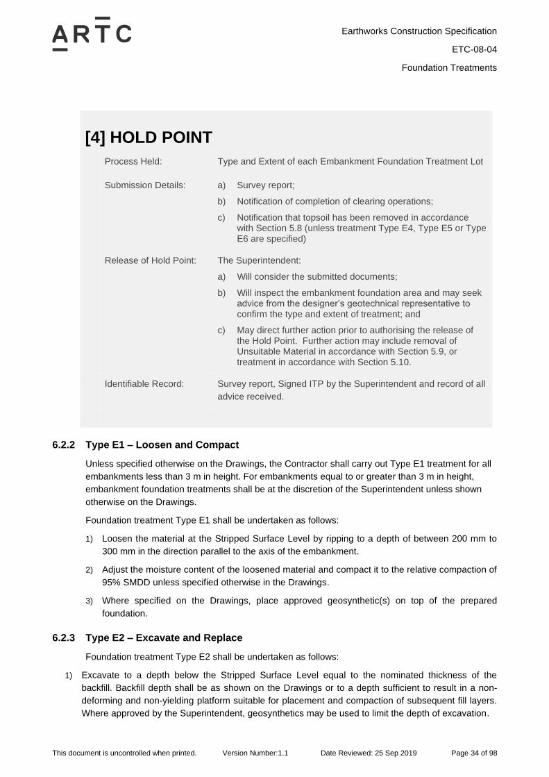
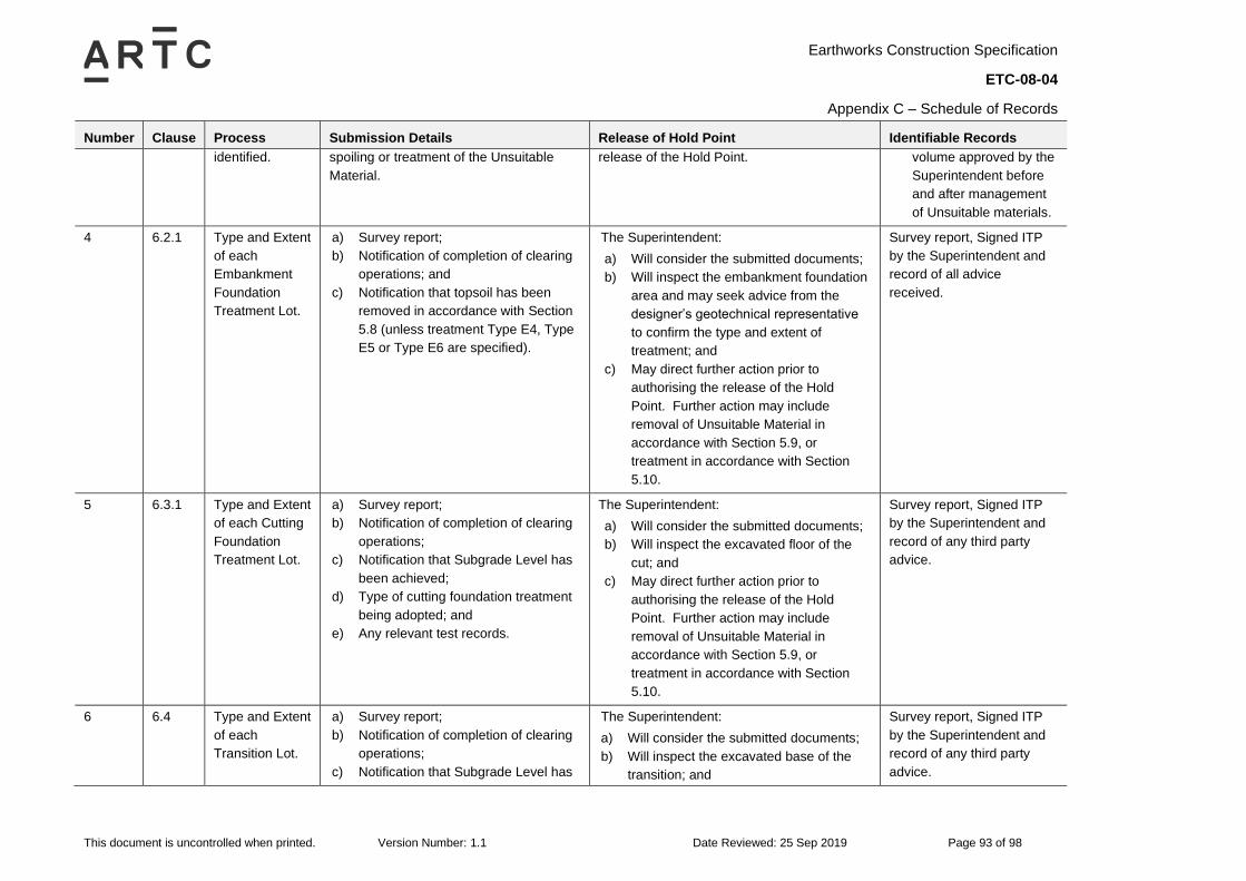
[4] HOLD POINT
Process Held: Type and Extent of each Embankment Foundation Treatment Lot
Submission Details: a) Survey report;
b) Notification of completion of clearing operations;
c) Notification that topsoil has been removed in accordance with Section 5.8 (unless treatment Type E4, Type E5 or Type E6 are specified)
Release of Hold Point: The Superintendent:
a) Will consider the submitted documents;
b) Will inspect the embankment foundation area and may seek advice from the designer’s geotechnical representative to confirm the type and extent of treatment; and
c) May direct further action prior to authorising the release of the Hold Point. Further action may include removal of Unsuitable Material in accordance with Section 5.9, or treatment in accordance with Section 5.10.
Identifiable Record: Survey report, Signed ITP by the Superintendent and record of all
advice received.
6.2.2 Type E1 – Loosen and Compact
Unless specified otherwise on the Drawings, the Contractor shall carry out Type E1 treatment for all
embankments less than 3 m in height. For embankments equal to or greater than 3 m in height,
embankment foundation treatments shall be at the discretion of the Superintendent unless shown
otherwise on the Drawings.
Foundation treatment Type E1 shall be undertaken as follows:
1) Loosen the material at the Stripped Surface Level by ripping to a depth of between 200 mm to
300 mm in the direction parallel to the axis of the embankment.
2) Adjust the moisture content of the loosened material and compact it to the relative compaction of
95% SMDD unless specified otherwise in the Drawings.
3) Where specified on the Drawings, place approved geosynthetic(s) on top of the prepared
foundation.
6.2.3 Type E2 – Excavate and Replace
Foundation treatment Type E2 shall be undertaken as follows:
1) Excavate to a depth below the Stripped Surface Level equal to the nominated thickness of the
backfill. Backfill depth shall be as shown on the Drawings or to a depth sufficient to result in a non-
deforming and non-yielding platform suitable for placement and compaction of subsequent fill layers.
Where approved by the Superintendent, geosynthetics may be used to limit the depth of excavation.
Earthworks Construction Specification
ETC-08-04
Foundation Treatments
This document is uncontrolled when printed. Version Number:1.1 Date Reviewed: 25 Sep 2019 Page 35 of 98
2) Place fill material in accordance with the Drawings or as directed by the Superintendent and in
compliance with the Earthworks Materials Specification.
3) Compact material in accordance with the requirements of this Specification.
6.2.4 Type E3 – Stabilised Foundation
For treatment Type E3, the Contractor shall construct a stabilised layer in accordance with the
Earthworks Materials Specification and the Contractor’s Project Specific Specification for stabilised
material.
Foundation treatment Type E3 shall be undertaken by treating the foundation using one of the
methods described below:
a) Increase the strength of the insitu material by undertaking stabilisation in accordance with
Section 10.4 of this Specification; The steps to be undertaken are the same as that for
foundation treatment Type E1 except that after loosening of the material at the Stripped Surface
Level, a stabilising agent (binder) is mixed into the loosened material in accordance with the
Earthworks Materials Specification and the Contractor’s Project Specific Specification for
stabilised material; or
b) Construct a stabilised layer using premixed stabilised material meeting the requirements of
Section 10.5 of this Specification. The steps to be undertaken are the same as that for
foundation treatment Type E2 except that after excavation (to Foundation Level), premixed
stabilised material is placed in accordance with the design and conforming to the Earthworks
Materials Specification and the Contractor’s Project Specific Specification for stabilised material.
6.2.5 Type E4 – Geosynthetic(s)
Foundation treatment Type E4 shall be undertaken as follows:
1) Where shown on the Drawings or directed by the Superintendent, excavate to a depth below the
Stripped Surface Level equal to the backfill thickness nominated for the foundation treatment
design.
2) Place a layer (or multiple layers) of geosynthetic. The geosynthetic shall be supplied and placed
in accordance with Section 11.
3) Place fill material in accordance with the design and conforming to the requirements of the
Earthworks Materials Specification.
6.2.6 Type E5 – Drainage Blanket
Foundation treatment Type E5 shall be undertaken as follows:
1) The Contractor shall ensure the foundation beneath the drainage blanket allows the drainage
blanket to drain after it is placed. A clear drainage path is to be maintained throughout the layer,
particularly at the outer edges of the embankment.
2) Place a geotextile complying with Section 11 of this Specification.
3) Construct a drainage blanket layer with a minimum compacted thickness of 300 mm. The
drainage blanket material must be spread and placed in such a way as to avoid segregation and
to ensure that it is not contaminated with foreign materials. The drainage blanket material must
meet the properties shown in the Earthworks Materials Specification, be compacted in
Earthworks Construction Specification
ETC-08-04
Foundation Treatments
This document is uncontrolled when printed. Version Number:1.1 Date Reviewed: 25 Sep 2019 Page 36 of 98
accordance with Section 13 of this Specification and conform to level tolerances stated in
Section 8.4.
4) Place a geotextile, complying with Section 11, at the interface of the drainage blanket material
and the embankment fill, thus fully encapsulating the drainage blanket material.
5) Provide drainage outlets at the ends of the drainage blanket layer as shown on the Drawings or
directed by the Superintendent.
The grading of the drainage blanket material shall be adjusted, within the limits specified in the
Earthworks Materials Specification, as to ensure that it provides a stable foundation for compaction
of the overlying embankment.
6.2.7 Type E6 – Bridging Layer
Foundation treatment Type E6 shall be undertaken as follows:
1) Demonstrate that it is impracticable to achieve the compaction specified on the drawings or
where no such value is provided, 95% SMDD.
2) Closely mow grass and cut trees and shrubs off at ground level.
3) If directed by the Superintendent, prior to placing the bridging layer, place a geotextile complying
with the requirements of Section 11.
4) Construct a bridging layer over the embankment foundation area to provide a stable platform
upon which a conforming earthworks layer can be constructed. The bridging layer material shall
be end-dumped, spread in a single layer and be constructed from rock fill material. The
maximum thickness of the bridging layer when completed must not exceed 800 mm.
5) Place a geotextile separation layer or graded rock fill overlay over the bridging material.
The Superintendent may require the construction of a trial section of the bridging layer prior to
authorising placement of the bridging layer in other areas.
Compaction of layers immediately above bridging layer needs to be conducted with care, particularly
avoiding the use of large vibrating rollers, to prevent the development of compaction-induced pore
pressures and de-stabilisation of the embankment.
Protection for exposed granular material shall be considered to prevent undermining of the
formation.
6.2.8 Type E7 – Special Treatment
Treatment Type E7, refers to the adoption of a project specific foundation treatment as shown on the
Drawings or as directed or agreed by the Superintendent.
6.3 Cuttings
6.3.1 Applying Treatments
Cutting foundation treatments are to be carried out after excavation to the Subgrade Level.
Prior to carrying out cutting foundation treatments in materials other than medium strength or
stronger rock, the Contractor is to carry out tests to determine the grading, CBR and PI values of the
material immediately below Subgrade Level, in the floor of the cutting, using the test methods stated
Earthworks Construction Specification
ETC-08-04
Foundation Treatments
This document is uncontrolled when printed. Version Number:1.1 Date Reviewed: 25 Sep 2019 Page 37 of 98
in the Earthworks Materials Specification. The Contractor may obtain samples for the grading, CBR
and PI tests from test pits prior to completion of excavation.
After reaching the cutting Subgrade Level, the Contractor is to present the area for inspection by the
Superintendent prior to constructing cutting foundation treatments. Proof rolling may be directed by
the Superintended in accordance with Section 13.5 of this Specification.
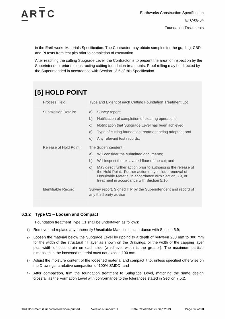
[5] HOLD POINT
Process Held: Type and Extent of each Cutting Foundation Treatment Lot
Submission Details: a) Survey report;
b) Notification of completion of clearing operations;
c) Notification that Subgrade Level has been achieved;
d) Type of cutting foundation treatment being adopted; and
e) Any relevant test records.
Release of Hold Point: The Superintendent:
a) Will consider the submitted documents;
b) Will inspect the excavated floor of the cut; and
c) May direct further action prior to authorising the release of the Hold Point. Further action may include removal of Unsuitable Material in accordance with Section 5.9, or treatment in accordance with Section 5.10.
Identifiable Record: Survey report, Signed ITP by the Superintendent and record of
any third party advice
6.3.2 Type C1 – Loosen and Compact
Foundation treatment Type C1 shall be undertaken as follows:
1) Remove and replace any Inherently Unsuitable Material in accordance with Section 5.9;
2) Loosen the material below the Subgrade Level by ripping to a depth of between 200 mm to 300 mm
for the width of the structural fill layer as shown on the Drawings, or the width of the capping layer
plus width of cess drain on each side (whichever width is the greater). The maximum particle
dimension in the loosened material must not exceed 100 mm;
3) Adjust the moisture content of the loosened material and compact it to, unless specified otherwise on
the Drawings, a relative compaction of 100% SMDD; and
4) After compaction, trim the foundation treatment to Subgrade Level, matching the same design
crossfall as the Formation Level with conformance to the tolerances stated in Section 7.5.2.
Earthworks Construction Specification
ETC-08-04
Foundation Treatments
This document is uncontrolled when printed. Version Number:1.1 Date Reviewed: 25 Sep 2019 Page 38 of 98
6.3.3 Type C2 – Excavate and Replace
Foundation treatment Type C2 shall be undertaken as follows:
1) Excavate to a depth below the Subgrade Level equal to the nominated thickness of the backfill. Excavate
and replace any Inherently Unsuitable Material exposed at the base of the excavation in accordance with
Section 5.9.
2) If directed by the Superintendent, determine the grading, CBR and PI values of the material in the floor
of the cutting (at Foundation Level) by the Test Methods stated in the Earthworks Materials Specification.
3) Compact the material exposed at the floor of the excavation (Foundation Level).
4) Place fill material in accordance with the Drawings or as directed by the Superintendent and in
compliance with the Earthworks Materials Specification.
5) After compacting in accordance with Section 13 of this Specification, trim the foundation treatment to
Subgrade Level, matching the same design crossfall as the Formation Level with conformance to the
tolerances stated in Section 7.5.2.
6.3.4 Type C3 – Stabilised Foundation
For treatment Type C3, the Contractor shall construct a stabilised layer in accordance with the
Earthworks Materials Specification and the Contractor’s Project Specific Specification for stabilised
material.
Foundation treatment Type C3 shall be undertaken as follows:
1) Treat the subgrade of the cutting by one of the methods described below:
a) Increase the strength of the insitu material by undertaking stabilisation in accordance with Section
10.4 of this Specification.
The steps to be undertaken are the same as that for foundation treatment Type C1 except that after
loosening of the material below the Subgrade Level, a stabilising agent (binder) is mixed into the
loosened material in accordance with the Earthworks Materials Specification and the Contractor’s
Project Specific Specification for stabilised material; or
b) Construct a stabilised layer using premixed stabilised material meeting the requirements of Section
10.5 of this Specification.
The steps to be undertaken are the same as that for foundation treatment Type C2 except that after
compaction of the floor of the cutting (at Foundation Level), premixed stabilised material is placed in
accordance with the design and conforming to the Earthworks Materials Specification and the
Contractor’s Project Specific Specification for stabilised material.
2) After compaction, trim the foundation treatment to Subgrade Level, matching the same design crossfall
as the Formation Level with conformance to the tolerances stated in Section 7.5.2
Earthworks Construction Specification
ETC-08-04
Foundation Treatments
This document is uncontrolled when printed. Version Number:1.1 Date Reviewed: 25 Sep 2019 Page 39 of 98
6.3.5 Type C4 – Geosynthetic(s)
Foundation treatment Type C4 shall be undertaken as follows:
1) Excavate to a depth below the Subgrade Level equal to the structural fill thickness nominated for the
foundation treatment. Trim the floor of the excavation (Foundation Level) to conform to the tolerance
stated in Section 7.5.2. Remove and replace any Inherently Unsuitable Material in accordance with
Section 5.9.
2) If directed by the Superintendent, determine the grading, CBR and PI values of the material in the
floor of the cutting (at Foundation Level) by the Test Methods stated in the Earthworks Materials
Specification;
3) Place a layer of geosynthetic on the floor of the cutting. Supply and placement of the geosynthetic in
accordance with Section 11.
4) Place structural fill material in accordance with the design and conforming to the requirements of the
Earthworks Materials Specification.
5) After compacting in accordance with Section 13 of this Specification, trim the foundation treatment to
Subgrade Level, matching the same design crossfall as the Formation Level with conformance to the
tolerances stated in Section 7.5.2.
6.3.6 Type C5 – Drainage Blanket
Foundation treatment Type C5 is to be adopted where shown on the Drawings and in all hard rock
cuttings where groundwater is known or suspected to occur or where approved by the
Superintendent. Treatment Type C5 shall be undertaken as follows:
1) Excavate to a depth below the Subgrade Level equal to the nominated thickness of the drainage
blanket and trim the floor of the cutting (Foundation Level) in such a manner as to ensure drainage of
the cutting occurs. The Contractor shall ensure the foundation beneath the drainage blanket allows
the drainage blanket to drain after it is placed. A clear drainage path is to be maintained throughout
the layer.
2) Remove, replace or treat all Unsuitable Material present in accordance with Section 5.9 of this
Specification.
3) For materials other than rock, compact the material exposed at the floor of the cutting with no less
than 6 passes of a 12t vibrating roller.
4) Except for where the cutting is in rock, place a geotextile complying with the requirements of
Section 11, at the interface of the foundation and drainage blanket material.
5) Construct a drainage layer with a minimum compacted thickness of 300 mm. The drainage layer
material must be spread and placed in such a way as to avoid segregation and to ensure that it is not
contaminated with foreign materials. The drainage blanket material must meet the properties shown
in the Earthworks Materials Specification, be compacted in accordance with Section 13 of this
Specification and conform to level tolerances stated in Section 7.5.2.
6) Place a geotextile, complying with the requirements of Section 11, at the interface of the drainage
blanket material and the overlying structural fill or capping layer, thus encapsulating the drainage
blanket material.
7) Provide end drainage outlet treatment as shown on the Drawings, or directed by the Superintendent.
Earthworks Construction Specification
ETC-08-04
Foundation Treatments
This document is uncontrolled when printed. Version Number:1.1 Date Reviewed: 25 Sep 2019 Page 40 of 98
The grading of the drainage blanket material shall be adjusted, within the limits specified in the
Earthworks Materials Specification, as to ensure that it provides a stable foundation for compaction
of the overlying layers.
6.3.7 Type C6 – Blinding Layer
Foundation treatment Type C6 is to be adopted where shown on the Drawings or in all uneven hard
rock cuttings where groundwater is not present. Foundation treatment Type C6 shall be undertaken
as follows:
1) Place a blinding layer comprising of capping material in accordance with the Earthworks Materials
Specification or other material approved by the Superintendent.
2) The thickness of the blinding layer shall be such that a smooth and stable surface is provided at
Subgrade Level that conforms to the geometry shown on the Drawings.
3) After compacting in accordance with Section 13 of this Specification, trim the foundation treatment to
Subgrade Level, matching the same design crossfall as the Formation Level with conformance to the
tolerances stated in Section 7.5.2.
6.3.8 Type C7 – Special Treatment
Foundation treatment Type C7, refers to the adoption of a project specific foundation treatment as
shown on the Drawings or as directed or agreed by the Superintendent. For example, special
treatments may be required to manage variable conditions such as rock floaters and corestones in a
clay matrix.
Earthworks Construction Specification
ETC-08-04
Foundation Treatments
This document is uncontrolled when printed. Version Number:1.1 Date Reviewed: 25 Sep 2019 Page 41 of 98
6.4 Transition Zones
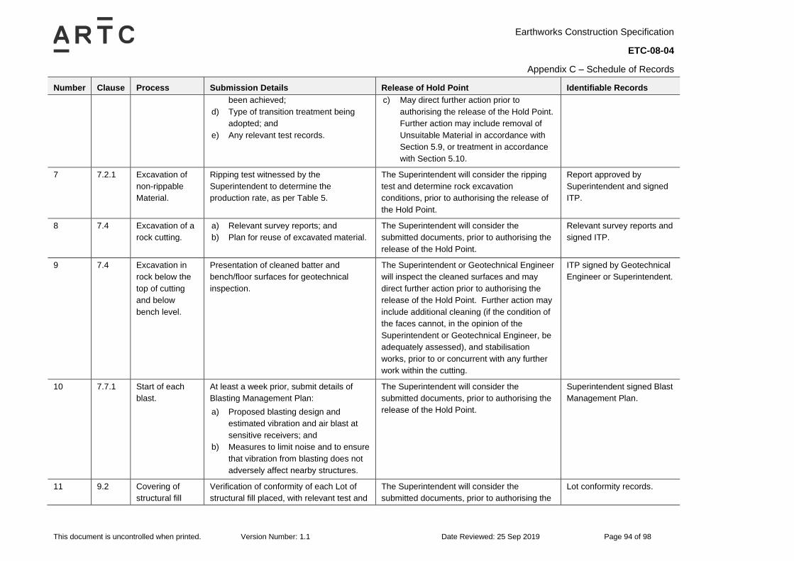
[6] HOLD POINT
Process Held: Type and Extent of each Transition Lot
Submission Details: a) Survey report;
b) Notification of completion of clearing operations;
c) Notification that Subgrade Level has been achieved;
d) Type of transition treatment being adopted; and
e) Any relevant test records.
Release of Hold Point: The Superintendent:
a) Will consider the submitted documents;
b) Will inspect the excavated base of the transition; and
c) May direct further action prior to authorising the release of the Hold Point. Further action may include removal of Unsuitable Material in accordance with Section 5.9, or treatment in accordance with Section 5.10.
Identifiable Record: Survey report, Signed ITP by the Superintendent and record of
any third party advice
6.4.1 New to Existing
A transition from an existing formation to a new formation shall be in accordance with the Drawings.
6.4.2 Type T1 – Formation Thickness Transition
A transition zone is required at each location of a variation in structural fill layer thickness to avoid
detrimental variations in formation stiffness supporting the track structure.
General transitions shall be constructed as shown in Detail B of Appendix B and as shown on the
Drawings. The transition zone shall extend over the length shown on the Drawings, or if not shown
on Drawings, as agreed by the Superintendent.
6.4.3 Type T2 – Cut to Fill Transition
A cut to fill transition zone is required when no structural fill is specified in the cutting or if the
thickness of structural fill overlying the embankment differs from the thickness of structural fill in the
cutting by more than 200 mm.
The Contractor shall trim the base of the transition excavation as shown on the Drawings, or if not
shown on Drawings, at a minimum gradient of 2% towards the transverse drain.
Earthworks Construction Specification
ETC-08-04
Foundation Treatments
This document is uncontrolled when printed. Version Number:1.1 Date Reviewed: 25 Sep 2019 Page 42 of 98
Following excavation to Subgrade Level in the cut, the Contractor shall carry out further excavation
in the cut to fill transition zone, to a depth equivalent to the Subgrade Level of the adjoining
embankment.
This additional excavation must extend into the cut for a distance of 10 m from the intersection line
resulting from the intersection of the plane of the Subgrade Level in the cut with the plane of the
stripped surface, as shown in Detail A of Appendix B. The 10 m is measured perpendicular to the
line of intersection between the two planes.
The cut to fill transition treatment shall extend for the full width of the formation however, must not
extend into the cut batter.
6.5 Terracing
Where embankments are to be constructed on or against any slopes or batter of existing
embankments (including batters resulting from the partial construction of embankments under the
Contract), and the existing slope or batter is steeper than 10H:1V in any direction, the Contractor is to
cut horizontal terraces into such slopes or batters which will be covered by the embankment to be
constructed.
6.5.1 Type T3 – Terracing
The existing slope or batter is to be stepped progressively in successive terraces as shown in Detail C
of Appendix B. Cut the terraces to a minimum depth of 300 mm at the steps except where the existing
slope or batter is 4H:1V or steeper, in which case the terraces must be cut to a minimum depth of
600 mm at the steps.
Cut the terraces progressively as the embankment is placed.
Inspect the floor of each terrace in accordance with Section 5.9 to check for any Unsuitable Material.
Unless directed otherwise by the Superintendent, incorporate the material thus excavated in
embankments in accordance with the Earthworks Materials Specification, Section 10 of this
Specification, or dispose of it as spoil in accordance with Section 5.10.
Unsuitable Material as defined in Section 5.9 exposed at the base of a terrace during the widening
shall be treated in accordance with Section 5.10. Loose or unstable materials exposed at the base of
a terrace during the widening shall be compacted to the requirements of Section 13 or removed and
replaced.
Earthworks Construction Specification
ETC-08-04
Excavation of Cuttings
This document is uncontrolled when printed. Version Number:1.1 Date Reviewed: 25 Sep 2019 Page 43 of 98
7 Excavation of Cuttings
7.1 General
Excavation of cuttings includes the following:
• Excavation of earth and rock material within the batter limits to the levels, grades, slopes and
dimensions shown on the Drawings.
• Benching or terracing of cut batters.
• Cleaning of batter surfaces.
• Foundation treatments in accordance with Section 6.3.
Materials of all classes encountered in cuttings shall be excavated and placed in embankments if
suitable, or removed to spoil if unsuitable. Unsuitable Material is to be treated in accordance with the
Section 5.9. Disposal of surplus suitable fill shall be at the approval of the Superintendent.
The occurrence of low strength shear zones, relict soil horizons and seepage zones in excavations
may require localised support as directed by the Superintendent. Such works should be based on site
specific geotechnical design.
The completed batter face shall be inspected by a Geotechnical Engineer to assess the requirements
for removal of any loose or potentially unstable blocks, or additional support systems as determined by
the exposed soil and rock conditions.
The degree of compaction of material in the subgrade of cuttings shall be as specified in the Drawings
or otherwise of that specified for structural fill in Section 13 of this Specification.
Excavation in cuttings shall be carefully planned before work starts so it can be carried out safely. The
Contractor shall consult with all relevant persons involved in the work, including the Superintendent,
Geotechnical Engineer, mobile plant operators and Designer where applicable. Planning for
excavations shall consider, but not limited to:
• Nature and/or condition of the ground and/or working environment.
• Effect of weather conditions on the Works.
• Static and dynamic loads near the excavation.
• Management of surrounding vehicular traffic and ground vibration.
• Type of equipment used for excavation work.
• Rippable and non-rippable material.
7.2 Non-Rippable Material
7.2.1 Bulk Excavations
Non-rippable material in bulk excavations shall be material which cannot be ripped at a production
rate exceeding those stated in Table 5 and all boulders greater than 1 m3.
Earthworks Construction Specification
ETC-08-04
Excavation of Cuttings
This document is uncontrolled when printed. Version Number:1.1 Date Reviewed: 25 Sep 2019 Page 44 of 98
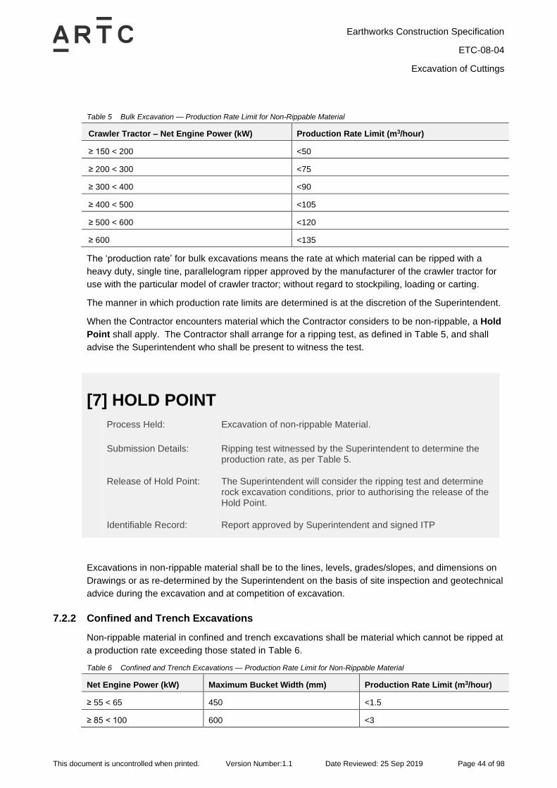
Table 5 Bulk Excavation — Production Rate Limit for Non-Rippable Material
Crawler Tractor – Net Engine Power (kW) Production Rate Limit (m3/hour)
≥ 150 < 200 <50
≥ 200 < 300 <75
≥ 300 < 400 <90
≥ 400 < 500 <105
≥ 500 < 600 <120
≥ 600 <135
The ‘production rate’ for bulk excavations means the rate at which material can be ripped with a
heavy duty, single tine, parallelogram ripper approved by the manufacturer of the crawler tractor for
use with the particular model of crawler tractor; without regard to stockpiling, loading or carting.
The manner in which production rate limits are determined is at the discretion of the Superintendent.
When the Contractor encounters material which the Contractor considers to be non-rippable, a Hold
Point shall apply. The Contractor shall arrange for a ripping test, as defined in Table 5, and shall
advise the Superintendent who shall be present to witness the test.
[7] HOLD POINT
Process Held: Excavation of non-rippable Material.
Submission Details: Ripping test witnessed by the Superintendent to determine the production rate, as per Table 5.
Release of Hold Point: The Superintendent will consider the ripping test and determine rock excavation conditions, prior to authorising the release of the Hold Point.
Identifiable Record: Report approved by Superintendent and signed ITP
Excavations in non-rippable material shall be to the lines, levels, grades/slopes, and dimensions on
Drawings or as re-determined by the Superintendent on the basis of site inspection and geotechnical
advice during the excavation and at competition of excavation.
7.2.2 Confined and Trench Excavations
Non-rippable material in confined and trench excavations shall be material which cannot be ripped at
a production rate exceeding those stated in Table 6.
Table 6 Confined and Trench Excavations — Production Rate Limit for Non-Rippable Material
Net Engine Power (kW) Maximum Bucket Width (mm) Production Rate Limit (m3/hour)
≥ 55 < 65 450 <1.5
≥ 85 < 100 600 <3
Earthworks Construction Specification
ETC-08-04
Excavation of Cuttings
This document is uncontrolled when printed. Version Number:1.1 Date Reviewed: 25 Sep 2019 Page 45 of 98
Net Engine Power (kW) Maximum Bucket Width (mm) Production Rate Limit (m3/hour)
≥ 115 < 135 750 <4.5
≥ 155 < 175 900 <7
≥ 200 < 235 1050 <10
≥ 235 To be confirmed by trials
The ‘production rate’ for confined and trench excavations means the rate at which material can be
excavated with a heavy duty toothed bucket or rock bucket (approved by the manufacturer of the
crawler excavator for use with the particular model of crawler excavator) for excavation only; without
regard to stockpiling, loading or carting. The bucket teeth shall be fitted with high penetration boots.
7.3 Cut Batters
Cut batters should be constructed in accordance with the Drawings. The batter slopes in cuttings may
be re-determined by the Superintendent, following a site inspection and investigation during
excavation. Where the Superintendent re-determines a slope, the Contractor may be entitled to claim
a variation in quantities in the earthworks schedule.
If the Contractor excavates the slope of a cutting beyond the specified line and the tolerance
applicable thereto, the Superintendent may authorise a minor change in the general slope of the
cutting to suit the convenience of the Contractor, but such a change shall not be regarded as a
redetermination of the slope under this Section, and no payment will be made for any increase in
excavation quantities resulting from the change in slope.
Batters will generally require progressive flattening at the ends of cuttings owing to the presence of
less stable material. Round off the tops of cuttings to the dimensions shown on the Drawings unless
otherwise directed.
The surface of batters in the cutting must be free of rills except for that resulting from pre-splitting or
line drilling boreholes. Treat the face of the batter progressively where such treatment is shown on the
Drawings.
Clear the cut faces of any loose or unstable material progressively as the excavation proceeds. The
Superintendent may direct that any overhanging, loose or unstable material, whether outside or
behind the specified slope, be removed.
Batters shall be carried around curves in an even and regular manner.
7.4 Cuttings in Rock
A Hold Point is required prior to commencement to excavation of a rock cutting.
Earthworks Construction Specification
ETC-08-04
Excavation of Cuttings
This document is uncontrolled when printed. Version Number:1.1 Date Reviewed: 25 Sep 2019 Page 46 of 98
[8] HOLD POINT
Process Held: Excavation of a rock cutting.
Submission Details: a) Relevant survey reports.
b) Plan for reuse of excavated material.
Release of Hold Point: The Superintendent will consider the submitted documents, prior to authorising the release of the Hold Point.
Identifiable Record: Relevant survey reports and signed ITP
In rock cuttings with slopes of 1H:1V or steeper, batters are to be inspected and assessed for stability
immediately following completion of excavation to the toe of the batter.
Prior to assessment by the Superintendent or Geotechnical Engineer, the Contractor shall clean the
batters and remove all loose and unstable blocks which are too large to be removed, by hand or
machine, unless otherwise directed by the Superintendent. The Contractor is to continue cleaning until
all loose rock and soil material is removed, and all rock and joint surfaces are sufficiently exposed so
that the Superintendent or Geotechnical Engineer can assess their condition and likely effect on the
stability of the batter.
The Contractor shall also clean the surface of all benches, unless otherwise directed by the
Superintendent.
[9] HOLD POINT
Process Held: Excavation in rock below the top of cutting and below bench level.
Submission Details: Presentation of cleaned batter and bench/floor surfaces for geotechnical inspection.
Release of Hold Point: The Superintendent or Geotechnical Engineer will inspect the cleaned surfaces and may direct further action prior to authorising the release of the Hold Point. Further action may include additional cleaning (if the condition of the faces cannot, in the opinion of the Superintendent or Geotechnical Engineer, be adequately assessed), and stabilisation works, prior to or concurrent with any further work within the cutting.
Identifiable Record: ITP signed by Geotechnical Engineer or Superintendent.
Following inspection, the Superintendent may direct additional stabilisation works, including changes
to the batter slope.
Earthworks Construction Specification
ETC-08-04
Excavation of Cuttings
This document is uncontrolled when printed. Version Number:1.1 Date Reviewed: 25 Sep 2019 Page 47 of 98
7.5 Tolerances in Cuttings
7.5.1 Batters
Batters in cuttings must not have undulations in the general plane of the batter. Excavation of
batters must comply with the tolerances given in Table 7.
Table 7 Cutting Batter Tolerances
Location Tolerance from Design Profile (mm)
Slope 1H:1V or flatter Steeper than 1H:1V
At level of toe of batter +0 / –150 +0 / –200
2 m above toe of batter and beyond +100 / –300 +100 / –300
Between level of toe of batter and 2 m
above toe of batter
Interpolate Interpolate
Notes:
1 Plus (+) is towards the formation and minus (–) is away from the track. Tolerances are to
be measured to a horizontal plane.
2 Bench widths must not be less than those shown on the Drawings.
If the batter is over-excavated beyond the tolerance applicable for the batter slope line, or after
cleaning the batter is beyond the tolerance applicable, restore the batter to the specified slope and
stability to the Superintendent's satisfaction. Proposals for restoration must take into account long
term stability, durability, and consideration of urban design solutions. The cost of restoring or re-
forming the batter will be borne by the Contractor.
The batter shall be constructed with a consistent profile to the satisfaction of the Superintendent.
For batters steeper than 1H:1V, if any section of the batter up to a height of 3 m above the toe of
batter has been over excavated beyond the tolerance limit specified, the Superintendent may direct
that the batter be re-formed to the average batter slope using a specified treatment.
7.5.2 Floor of Cutting
Finish surface levels on the floors of cuttings and transitions shall not exceed the tolerances detailed
in Table 8. The tolerances in Table 11 have precedence.
Table 8 Cutting Level Control Tolerances
Location Tolerance from Design Profile (mm)
Floor of the cutting other than in rock +0 to -40
Floor of the cutting in rock +0 to -80
Notes:
1 Minus (-) is away from the track and plus (+) is towards the track. Tolerances are
measured perpendicular to the formation surface.
2 The floor of cuttings other than rock shall not deviate more than 20 mm over any 3 m
length.
Earthworks Construction Specification
ETC-08-04
Excavation of Cuttings
This document is uncontrolled when printed. Version Number:1.1 Date Reviewed: 25 Sep 2019 Page 48 of 98
7.6 Benching in Cuttings
Construct benches at cut batters as shown on the Drawings, to provide drainage and erosion control,
to provide geotechnical stability, and to allow access for maintenance purposes. Notwithstanding the
tolerances permitted under Table 7, bench widths must not be less than those shown on the
Drawings.
The floor of the bench must not vary from levels shown on the Drawings by more than the tolerances
shown in Table 8, but the bench must have a crossfall to drain water away from the cut face
immediately below the bench. Provide and maintain longitudinal drainage to prevent ponding of water
on the benches, overtopping of batters and direct water away from the formation along natural
contours.
Construct bench drains, where shown on the Drawings, progressively as each batter face is
completed.
Maintain and regularly clean the benches of any loose materials throughout the Contract period. The
cost of such maintenance and cleaning of benches is deemed to be included in the rates generally.
7.7 Blasting
7.7.1 General
This section outlines requirements for blasting in cuttings and is not applicable to tunnels.
Blasting of cuttings shall be undertaken as outlined below and in accordance with the requirements
of the relevant local and state authorities, government regulations, license conditions and relevant
Australian Standards.
The Contractor shall provide a Blasting Management Plan and any dilapidation surveys as required
by the Superintendent prior to commencement of blasting.
[10] HOLD POINT
Process Held: Start of each blast.
Submission Details: At least a week prior, submit details of Blasting Management Plan:
a) proposed blasting design and estimated vibration and air blast at sensitive receivers; and
b) measures to limit noise and to ensure that vibration from blasting does not adversely affect nearby structures.
Release of Hold Point: The Superintendent will consider the submitted documents, prior to authorising the release of the Hold Point.
Identifiable Record: Superintendent signed Blast Management Plan
Earthworks Construction Specification
ETC-08-04
Excavation of Cuttings
This document is uncontrolled when printed. Version Number:1.1 Date Reviewed: 25 Sep 2019 Page 49 of 98
The Blasting Management Plan must include a detailed procedure to be followed in the event of a
misfire of the charges.
Prior to commencement of any blasting activities, the Contractor must obtain all necessary approvals
and licences from the appropriate authorities.
When blasting operations are being carried out, take precautions relating to the safety of persons
and animals. Close any roads likely to be affected by the blasting to traffic and erect the appropriate
signs in accordance with state government road authority requirements.
The Contractor shall undertake a dilapidation survey following blasting at the discretion of the
Superintendent.
7.7.2 Blasting Records
The Contractor shall maintain accurate records of each blast including the details listed below:
• Date, identification number and time of blast.
• Location, number and diameter of blast holes loaded.
• Site plan showing (at a minimum) locations and identification numbers.
• Depth of each drill hole loaded.
• Inclination of drill holes.
• Burden(s) and spacing(s).
• Types and amounts of explosives used.
• Maximum instantaneous charge.
• Initiation Plan.
• Length and type of stemming in each blast hole.
• Ground vibration and noise levels at measuring locations.
• Regulatory notifications.
• Details and all relevant documentation relating to all breaches which have occurred.
The records must be written as the holes are loaded, and must be signed by the shotfirer. The
Contractor shall provide a copy of the records to the Superintendent on the day of the blast.
7.7.3 Pre-Splitting or Line Drilling
7.7.3.1 General
Use pre-splitting or line drilling to produce a uniform and neat batter surface after excavation and
reduce over-break. The boreholes used in pre-splitting or line drilling must be straight, parallel and
in the designed plane of the batter.
The diameter, spacing, and loading of presplit holes shall be designed so as to result in a neat
break.
If the depth of the cut is more than can be drilled from the top, the Contractor shall include in their
Blasting Management Plan a methodology that complies with the Drawings.
The Superintendent will give consideration to an alternative method of excavation and preparation
of the cut face so as to produce a result equivalent to that produced from pre-splitting or line
drilling. Approval to such alternative methods will be granted at the absolute discretion of the
Superintendent, who may require a trial section of the proposed method to be carried out to
demonstrate its suitability.
Earthworks Construction Specification
ETC-08-04
Excavation of Cuttings
This document is uncontrolled when printed. Version Number:1.1 Date Reviewed: 25 Sep 2019 Page 50 of 98
7.7.3.2 Hole Diameter and Hole Spacing
Where pre-splitting or line drilling is carried out, the centre-to-centre spacing of drill holes must not
exceed the values in the Table 9 below.
Table 9 Hole Diameter and Spacing for Pre-splitting or Line Drilling
Cut Batter Treatment Hole Diameter (mm) Maximum Hole Spacing
(mm)
Pre-splitting 38-51 450
Pre-splitting 51-64 750
Pre-splitting 76-89 900
Line Drilling < 51 150
Line Drilling 51-76 250
7.7.3.3 Pre-splitting or Line Drilling Prior to Blasting
Prior to commencing blasting, batters with gradients 1H:1V or steeper must be pre-split or line
drilled to the design batter profile to the spacings shown in Table 9 to produce a uniform and neat
batter surface after excavation which is acceptable to the Superintendent.
Such burden blasting must not damage the batter face.
7.7.4 Control of Airblast
The airblast (noise) at noise sensitive locations must not exceed the overpressure limits required by
relevant state authorities, environmental licences, approvals, nearby asset owners and the ANZECC
Technical Basis for Guidelines to Minimise Annoyance due to Blasting Overpressure and Ground
Vibration. In general, a monitoring location will be sited at the perimeter of the noise sensitive
location at the point closest to the maximum charge.
The Contractor shall monitor airblast to verify that the specified limits are not exceeded. The
equipment used for such monitoring must be calibrated annually by a National Association of Testing
Authorities (NATA) accredited testing facility or manufacturer’s facility approved by the
Superintendent. All readings from the monitoring must be reported on test certificates, which must
indicate clearly compliance or non-compliance with the requirements of this Specification. Provide a
copy of the monitoring record to the Superintendent.
In the event that the measured airblast exceeds the specified limits, suspend further blasting work
and take additional steps and precautions to ensure that, for any future blast, the limiting airblast
must not be exceeded. Do not resume any blasting until details of the additional steps and
precautions have been provided to the Superintendent.
7.7.5 Control of Ground Vibration from Blasting
Ground vibration at sensitive locations must not exceed the limits required by relevant state
authorities, environmental licenses, approvals, nearby asset owners and the ANZECC Technical
Basis for Guidelines to Minimise Annoyance due to Blasting Overpressure and Ground Vibration. In
general, a monitoring location will be sited at the perimeter of the structure or building at the point
closest to the maximum charge. The measurement process for determining verification of
compliance with ANZECC is to be in accordance with AS 2187.2.
Earthworks Construction Specification
ETC-08-04
Excavation of Cuttings
This document is uncontrolled when printed. Version Number:1.1 Date Reviewed: 25 Sep 2019 Page 51 of 98
The equipment used for monitoring must be calibrated annually by a NATA accredited testing facility
or manufacturer’s facility approved by the Superintendent. All readings from the monitoring must be
reported on test certificates, which must indicate clearly compliance or non-compliance with the
requirements of this Specification. Provide a copy of the monitoring record to the Superintendent.
To minimise the risk of peak particle velocity limits being exceeded, develop a blasting site
relationship between peak particle velocity, distance and blasting charge and submit to the
Superintendent.
Earthworks Construction Specification
ETC-08-04
Embankments
This document is uncontrolled when printed. Version Number:1.1 Date Reviewed: 25 Sep 2019 Page 52 of 98
8 Embankments
8.1 General
Embankment construction includes:
• Preparation of foundation areas over which fill material is to be placed as described in Section 6
and backfilling of excavations undertaken for foundation treatments;
• Placement and compaction of conforming material in areas from which Unsuitable Material has
been removed in accordance with Section 5.9, and in areas where material below the Subgrade
Level has been removed in cut/fill transitions;
• The placement and compaction of fill material, both general fill and materials of specified quality in
nominated zones throughout the Works, including at spill through bridge abutments where
subsequent pile foundation works are to be undertaken; and
• Works to the geometry shown on the Drawings.
The Contractor shall programme and manage the Works as detailed in the PQP so that material of the
quality specified in the Earthworks Materials Specification is available when required. Embankments
shall be constructed, up to Subgrade Level, from materials approved by the Superintendent for use in
embankments and obtained from cuttings and borrow areas. If there is a deficiency of materials from
cuttings, the Superintendent may approve that cuttings be widened, benched or cutting batters
flattened. Materials from other sources may be supplied if approved by the Superintendent.
Prior to placement, the Contractor shall process those materials which do not meet the requirements
of the Earthworks Materials Specification to achieve conformity. The Contractor is to select the
methods of excavation, transport, depositing and spreading of the fill material so that the placed
material in any Lot is homogeneous.
The embankment batter slopes shown on the Drawings may be re-determined by the Superintendent
depending upon the materials encountered.
The full width of the embankment shall be compacted to the requirements specified in Table 19.
8.2 Earth Fill Embankments
8.2.1 Earth Fill Material
8.2.1.1 Homogenous Embankment
Homogenous earth fill embankments are to be constructed using General Earth Fill materials
meeting the requirements of the Earthworks Materials Specification.
Coarse fragments must be broken down to smaller sized particles and evenly distributed
throughout the layer to prevent the formation of voids and to produce a dense compact
embankment. To meet this requirement, additional fine grained material may need to be obtained
from other places within the Site or by a change in the method of winning and processing the
material.
Earthworks Construction Specification
ETC-08-04
Embankments
This document is uncontrolled when printed. Version Number:1.1 Date Reviewed: 25 Sep 2019 Page 53 of 98
8.2.1.2 Zoned Embankments
The Contractor shall construct an embankment that maximises the use of cut or locally won source
materials and minimises the amount of imported fill materials.
The zoned embankment definitions for the cross section are shown in Figure 2, with placement
depth criteria and material requirements in Section 13 of this Specification and the Earthworks
Materials Specification.
In general, the Outer Zone material shall be general fill Type A durable, erosion resistant material,
the Upper Zone shall be general fill Type A and Type B, and the Lower Zone may be general fill
Type C, Type D and rockfill, all in accordance with their respective placement depth criteria
specified in the Earthworks Materials Specification.
8.2.1.3 Bridge Abutments
At bridge abutments, Select Fill material conforming to the Earthworks Materials Specification is to
be placed within the zone shown on the Drawings, or where not shown, in accordance with
Standard Drawing B0305.
Each lift must be compacted in accordance with the requirements for Select Fill Adjacent to
Structures as detailed in Section 13 of this Specification.
8.2.2 Earth Fill Placement and Compaction
Earth fill embankments shall be constructed by placing approved fill materials in horizontal layers for
the full width of the embankment. Each layer shall have a compacted thickness not exceeding those
specified in Section 13 unless demonstrated by field trials and approved by the Superintendent.
Compaction of fill shall occur for the full width of the embankment. This may require the embankment
to be overfilled and cut back.
Earth fill material for embankment construction is to be placed in lifts parallel to the grade line.
Coarse fragments shall be broken down and well distributed through the filling, and sufficient fine
material shall be placed around the larger material as it is deposited to fill the voids and produce a
dense compact embankment. Where insufficient fine material is present to fill the voids, additional
fine material shall be obtained from other places in the work or by a change in the method of
winning.
Where the Contractor wishes to compact any fill material in lifts exceeding those specified in Section
13 (for the material type), they shall demonstrate by trial compaction to the Superintendent's
satisfaction, that the compaction plant is capable of efficiently achieving the specified relative
compaction through the lift thickness.
Earth fill is not to be placed on a lift which has a moisture content outside the specified moisture
content range; is soft, unstable or rutted; or which has become mixed with foreign matter. The
underlying layer shall be corrected to comply with the corresponding requirements of Section 13
before spreading of the next fill lift.
8.3 Rock Fill Embankments
8.3.1 Rock Fill Material
Material for rock fill must comply with the Earthworks Materials Specification. The constituent
particles must be of uniform strength and soundness. Material that does not meet the requirements
Earthworks Construction Specification
ETC-08-04
Embankments
This document is uncontrolled when printed. Version Number:1.1 Date Reviewed: 25 Sep 2019 Page 54 of 98
for rock fill must be broken down further into finer particles, or have additional fines incorporated, and
used elsewhere.
The Contractor shall adjust the working methods employed in the excavation of cuttings so as to
produce rock fill material of the grading and rock strength specified. Such working methods may
include screening and, if necessary, secondary processing.
8.3.2 Rock Fill Placement and Compaction
The Contractor shall nominate to the Superintendent the proposed areas of rock fill. Unless shown
otherwise on the Drawings, do not place rock fill in areas where earth fill has previously been
constructed.
The Contractor shall shape and treat the foundations under rock fills to maintain drainage and to
ensure that erosion of the foundation will not occur. Where shown on the Drawings or directed by
the Superintendent, place a geotextile, complying with the requirements of Section 11, over the
foundation area prior to placing the rock fill.
Rock fill material is to be placed and spread in such a way as to avoid segregation and to ensure
that it is not contaminated with foreign material. The completed rock fill lift thickness must not exceed
that specified in Table 18 of this Specification, unless approved otherwise by the Superintendent.
Rockfill shall not be placed within 3 m of structures without prior approval by the Superintendent.
The Contractor shall not dump rock within 5 m of structures.
8.3.3 Surplus Rock Fill Material
If the Contractor requests and is given approval by the Superintendent to construct an earth fill
embankment in some or all of the nominated rock fill locations, and a surplus of rock, capable of
being processed for rock fill, is later found to exist, then surplus shall be treated by either:
• Processing the material for use as general fill;
• Removal of general fill, and placement of the surplus rock as rock fill, at the Contractors cost; or
• Disposed of as spoil.
8.4 Embankment Tolerances
8.4.1 Batter Slopes
When completed, the batters of embankments must conform to those shown on the Drawings unless
otherwise authorised or re-determined by the Superintendent.
The tolerances for construction of embankment batters are detailed in Table 10.
Table 10 Embankment Batter Tolerances
Location Tolerance from Design Profile (mm)
At formation level -0 / +150
Between top of formation and 1 m below top of formation -0 / +150
Beyond 1 m below top of formation -0 / +300
Notes:
Earthworks Construction Specification
ETC-08-04
Embankments
This document is uncontrolled when printed. Version Number:1.1 Date Reviewed: 25 Sep 2019 Page 55 of 98
1 Minus (-) is towards the formation and plus (+) is away from the track. Tolerances are to be
measured to a horizontal plane.
Undulations in the general plane of the batter are not acceptable. The completed batter must be free
of rills running down the face of the batter. Batter profiles shall be uniform through their entire length
and continue in regular lines around curves.
The Contractor shall promptly remove any loose material on the batters as the work progresses.
Placement of additional material on the existing embankment batters must be carried out in the
same manner as that specified for placement of hillside embankments in Section 6.5.
8.4.2 Level Controls
The Contractor shall finish the surface levels of the earthworks layers and zones to the design
surface levels less the nominated thicknesses of the relevant overlying courses and zones to within
the tolerances detailed in Table 11.
Table 11 Embankment Level Control Tolerances
Location Tolerance from Design Profile (mm)
Top of the structural fill layer other than in rock +0 to -50
Top of the general fill zone +40 to -40
Floor of the benches +0 to -100
Finished surface of the capping layer +0 to -15
3 m straight edge (or equivalent method)
<10 mm difference
Capping layer crossfall between 1V:25H and 1V:35H
Notes:
1 Minus (-) is away from the track and plus (+) is towards the track. Tolerances are
measured perpendicular to the formation surface.
8.5 Scour Protection for Embankments
8.5.1 General
Where shown on the Drawings, the Contractor shall provide scour protection of clean, hard, durable
rock over embankment batters (including embankments at bridge structures) meeting rock protection
requirements of the Earthworks Materials Specification.
The Contractor may elect, with the approval of the Superintendent, to place surplus rock conforming
to Section 8.3.3 as rock facing. The scour protection shall be placed outside of the general
embankment dimensions.
8.5.2 Placing Rock Protection
Placement of the rock protection shall be in layers as per the design after the earthworks
construction. Place the rock with its least dimension vertical, and such that mechanical interlock
between the larger stones occurs.
Earthworks Construction Specification
ETC-08-04
Embankments
This document is uncontrolled when printed. Version Number:1.1 Date Reviewed: 25 Sep 2019 Page 56 of 98
Provide a geotextile, complying with the requirements of Section 11, as a separation between the
earth fill material and the rock protection.
Fill the space between larger rocks in the rock facing and adjacent fill material with progressively
smaller rocks to form a graded filter which prevents the leaching out of fines from the fill material but
which does not overfill the voids between larger rocks, or cause the larger rocks to lose contact with
one another.
Remove any excess of fine material surrounding any rock placed within the rock facing by removing
the rock, removing the excess fine material and re-placing the rock.
Earthworks Construction Specification
ETC-08-04
Formation
This document is uncontrolled when printed. Version Number:1.1 Date Reviewed: 25 Sep 2019 Page 57 of 98
9 Formation
9.1 Placing and Compacting Structural Fill and Capping Materials
The finished cutting and embankment surfaces including capping layer shall conform to the profile
specified on the Drawings and be in accordance with tolerances specified in Section 7.5.2 and
Section 8.4.2 of this Specification. The finished surface immediately below the capping layer and the
finished surface of the capping layer shall have no depressions or ridges which could hold water or
prevent full drainage.
The top of the structural fill and capping layers shall be compacted, trimmed to the final profile and
tested (including but not limited to proof rolling) to meet the design requirements.
Structural fill and capping materials shall be spread in uniform horizontal lifts for the full width of the lift
that will provide the specified compacted thickness. Spreading shall be undertaken by a method that
will ensure segregation does not occur, and so as not to rut or disturb the compacted material beneath
it.
Where required for compaction purposes, water shall be added and mixed uniformly with the structural
fill and capping material by approved mechanical means. Compaction shall continue until the layer
shows no further movement under the compacting equipment and the density specified in Table 19 is
achieved.
The Contractor may proceed in the absence of conformity records for Hold Points contained in Section
9.2 and 9.3 at their own risk.
9.2 Structural Fill Layer(s)
All structural fill shall be supplied and/or won to meet the materials requirements of the Earthworks
Materials Specification.
The structural fill layer shall be constructed in a continuous layer to a minimum compacted thickness
defined in Table 18, Table 19 or as specified otherwise on the Drawings, to a level 30 mm above the
base of the capping layer.
[11] HOLD POINT
Process Held: Covering of structural fill layer
Submission Details: Verification of conformity of each Lot of structural fill placed, with relevant test and survey reports.
Release of Hold Point: The Superintendent will consider the submitted documents, prior to authorising the release of the Hold Point.
Identifiable Record: Lot conformity records
Earthworks Construction Specification
ETC-08-04
Formation
This document is uncontrolled when printed. Version Number:1.1 Date Reviewed: 25 Sep 2019 Page 58 of 98
9.3 Capping Layer
Immediately prior to the placement of the capping, the structural fill layer shall be trimmed by grading
to the final profile and compacted by a minimum of three passes of a smooth steel drum roller that has
a static mass not less than 10 tonnes.
All formation capping material shall be supplied to meet the requirements of the Earthworks Materials
Specification.
[12] HOLD POINT
Process Held: Placement of each Lot of Capping.
Submission Details: Test reports verifying conformity of each Lot of material for use in Capping Layer.
Release of Hold Point: The Superintendent will consider the submitted documents, prior to authorising the release of the Hold Point.
Identifiable Record: Material Lot conformity record
The top of the capping layer shall be graded and trimmed and additional capping material shall be
added as necessary to produce an even, tight and dense surface. The finished rolled surface shall be
true to profile to a tolerance as defined by Section 8.4.2 and shall be free of depressions and ruts.
[13] HOLD POINT
Process Held: Covering of each Lot of Capping.
Submission Details: Verification of conformity of each Lot of Capping placed, with relevant test and survey reports.
Release of Hold Point: The Superintendent will consider the submitted documents, prior to authorising the release of the Hold Point.
Identifiable Record: Lot conformity record
Where new works join existing track, the levels and crossfall of the capping layer shall be placed in
accordance with the drawings to ensure proper drainage of both the new and existing formation.
Earthworks Construction Specification
ETC-08-04
Stabilisation
This document is uncontrolled when printed. Version Number:1.1 Date Reviewed: 25 Sep 2019 Page 59 of 98
10 Stabilisation
10.1 Stabilised Material
Stabilised fill shall meet stabilised materials criteria specified in the Earthworks Materials Specification
and the Contractors Project Specific Specification for use of stabilised materials.
[14] HOLD POINT
Process Held: Use of stabilised material in the subgrade, embankment fill and
formation.
Submission Details: Provision of a stabilised material design by the Designer and Project Specific Specification for stabilised material, including results and details of laboratory testing, stabilisation method, stabilisation trial section, stabilisation quality control and stabilisation quality assurance details.
Release of Hold Point: The Superintendent will consider the submitted document, prior to authorising the release of the Hold Point.
Identifiable Record: Approved Project Specific Specification for the stabilised material
and the stabilisation quality plan
10.2 Stabilised Fill Layers
Each stabilised fill layer worked shall be parallel to the finished fill surface and shall extend the full
width of the treatment area. The stabilised fill shall be place in compacted layers not greater than
300 mm nor less than 100 mm to achieve a uniformity, free from evidence of any segregation.
Each lift of stabilised fill shall be completed within the specified timeframe. Where the treatment area
is greater than one day’s production, the layer may be subdivided into lifts, with overlapping runs and
construction joints staggered horizontally and vertically over the area.
Overlying layers shall not be placed until the stabilised fill layer has been cured to meet the
performance requirements of the Project Specific Specification for stabilised materials.
Adjoining stabilisation passes shall be completed with a minimum overlap of 300 mm. Any overlaps in
adjoining stabilised materials must be completed within the working time of each material respectively.
Where multiple lifts are placed, each lift shall extend a minimum 500 mm past the underlying lift, so as
to reduce differential movement between the stabilised layer and the adjoining material.
The stabilised material’s moisture content, as specified in the Contractors Project Specific
Specification for stabilised materials, must be uniformly maintained while placing and compacting the
stabilised material. The Contractor shall apply a uniform compactive effort, both longitudinally and
transversely, while meeting the requirements for density, width, shape, level and surface finish as
Earthworks Construction Specification
ETC-08-04
Stabilisation
This document is uncontrolled when printed. Version Number:1.1 Date Reviewed: 25 Sep 2019 Page 60 of 98
specified in the Contractors Project Specific Specification for stabilised materials and this
Specification.
Each layer of stabilised material must be tested and shown to comply with the requirements of the
Contractors Project Specific Specification for stabilised materials and this Specification, prior to
placing subsequent layers. The Contractor may proceed in the absence of conformity records for Hold
Points contained in the Contractors Project Specific Specification for stabilised materials and this
Specification at their own risk.
10.3 Stabilisation Trial Section
The Contractors Project Specific Specification for stabilised materials shall provide details on how the
Contractor shall carry out a preliminary trial of the proposed stabilising operations for each material
and binder type proposed to be used for stabilised fill. The trial shall determine:
• The effectiveness of the plant, including depth of stabilisation (maximum 300 mm per single pass
unless approved otherwise by the Superintendent).
• The number of passes of the stabilising machine necessary to achieve the specified mixing.
• The desirable moisture content, temperature and working time for compaction operations.
• The number of passes of the compaction machine necessary to achieve the specified compaction.
• The compacted depth of layer being worked, including the allowance for trimming to spoil and
level tolerances.
• Compliance of stabilised material to the Earthworks Materials Specification and the Contractors
Project Specific Specification for stabilised materials.
• Development of QA/QC testing schedule, including alternative test methods (detailed in the
Earthworks Materials Specification).
The trial section shall be located within the Works area and shall remain open for inspection and
testing as required by the Designer.
Earthworks Construction Specification
ETC-08-04
Stabilisation
This document is uncontrolled when printed. Version Number:1.1 Date Reviewed: 25 Sep 2019 Page 61 of 98
[15] HOLD POINT
Process Held: Stabilised fill trial section in the embankment and formation open
for inspection and testing as required by the Designer.
Submission Details: a) Provision of a stabilised material test results which
demonstrate compliance with design criteria and specification
requirements.
b) The Contractor’s Project Specific Specification for stabilised materials inclusive of the results of the trial.
Release of Hold Point: The Superintendent will consider the submitted documents, prior to authorising the release of the Hold Point.
Identifiable Record: Stabilised material test results, approved revisions of the
Contractor’s Project Specific Specification for stabilised materials
The trial section shall be tested with a range of field and laboratory test methods to provide
correlations between the test methods, conformation of design parameters and the suitability of
compliance acceptance limits in the Earthworks Materials Specification. Test methods may include but
not be limited to those specified in the Earthworks Materials Specification.
The results of the trial testing programme will be reviewed by the designer, approved by the designer
and Superintendent, and used to review and change, if needed, the testing schedule detailed in the
Contractors Project Specific Specification for stabilised materials.
10.4 In Situ Stabilisation Method
The spreading equipment shall be a stabilising agent spreader which has been specifically designed
for such work. The spreader shall be capable of uniformly distributing the stabilizing agent and
accurately controlling the spread rate such that when mixing is complete, the stabilisation agents
content shall be in accordance with the Contractors Project Specific Specification for stabilised
materials (as required by the Earthworks Materials Specification). The spreader shall be equipped
with gates to vary the width of spread and with electronic weigh scales to give daily totals of product
used.
Cutting, pulverising, mixing, adding water and spreading of mixed material shall be accomplished
using a stabilising machine specifically designed for stabilisation.
The stabilising machine shall also satisfy the following requirements:
• It shall be capable of producing a uniformly mixed material throughout the specified depth of the
work.
• It shall not disturb the layer beneath the lift to be stabilised.
• It shall be equipped with a variable depth of cut control, and an accurate gauge to measure depth
of cut which is readily visible to the operator.
Earthworks Construction Specification
ETC-08-04
Stabilisation
This document is uncontrolled when printed. Version Number:1.1 Date Reviewed: 25 Sep 2019 Page 62 of 98
• It shall have provision for adding water automatically through a system comprising a pump, flow
meter, variable control valve and full width spray bar.
The Contractor shall keep daily records of the amounts of stabilising agent used and actual spread
rates obtained per section treated and submit them to the Superintendent on a weekly basis.
The percentage of stabilising agent determined in accordance with this Section shall be maintained
within ± 10% by mass of the stabilising agent content specified in Contractors Project Specific
Specification for stabilised materials (as required by the Earthworks Materials Specification)
throughout the stabilisation works.
10.5 Plant Mixed Stabilisation Method
Stabilised material may be supplied as a plant mixed product which meets the design requirements of
the Earthworks Materials Specification and the Contractors Project Specific Specification for stabilised
materials.
Immediately prior to placement of the stabilised material, lightly scarify or tyne the surface on which it
is to be placed to a depth not exceeding 25 mm.
Process the mix in a mixing plant of the driven pugmill type. The mixing plant may be either a batch or
continuous type. The mixing plant shall be fitted with a measuring device to allow accurate
measurement of the amount of stabilising binder and additives being added to the mix. The mass of
charge in a batch mixer or the rate of feed to a continuous type mixer shall not exceed that which will
permit complete mixing of all material.
The mixing plant shall be operated in accordance with the manufacturer's recommendations. Mixing
of material shall be continued until the quarry material, binder, retarder and water are evenly
distributed through the mass and a uniform mixture of unchanging appearance is obtained.
The plant must be capable of processing the nominated lot sizes within the curing period and of
incorporating the stabilising agent to an accuracy of ±10% of the nominated rate. The process
operation must effectively avoid segregation occurring in the mix.
Production of each nominated mix shall be such that the proportion of stabilising binder incorporated is
within the specified tolerances. The Contractor shall implement a testing regime to demonstrate that
the binder content complies with Contractors Project Specific Specification for stabilised materials and
the Earthworks Materials Specification.
At the end of each day's production, the average percentage of stabilising binder added to the plant
mixed stabilised material shall be calculated (as a percentage of the dry mass of the material being
bound, to 0.05%), from:
• The total amount of binder used that day (determined from delivery dockets, silo dippings, etc.);
and
• The total quantity of material mixed and placed in the works that day (determined by appropriate
measurement).
During transportation to the site, the load shall be completely covered with a tarpaulin or similar heavy
cover to protect the material against the effect of sun and rain. The cover shall not be removed until
the load is about to be tipped.
The rate of delivery shall be sufficient to enable all spreading, shaping and compaction to be carried
out within the working time as defined by the supplier.
Earthworks Construction Specification
ETC-08-04
Stabilisation
This document is uncontrolled when printed. Version Number:1.1 Date Reviewed: 25 Sep 2019 Page 63 of 98
10.6 Stabilisation Quality Requirements
10.6.1 In Situ Stabilisation
For in situ stabilisation method (Section 10.4) the Contractor shall prepare and implement a
Stabilisation Quality Plan that includes:
• Details of binder design criteria, including design strength and material types, complying with
the requirements of the Earthworks Materials Specification.
• Details of the type of stabilisation plant proposed, including type, output capacity and method of
controlling binder content and moisture content (including methods to ensure uniformity).
• Method for determining stabilised material density and binder spread rate.
• Details of trial (Section 10.3).
• Details of any retarder to be used with binder.
• Details of the curing period and conditions required prior to the placement of the next layer.
• Records demonstrating sulfates or other deleterious chemicals are not present in sufficient
quantities to effect stabilisation.
• Procedures for calibration of plant (including frequency).
• Detailed procedures for stabilised fill construction.
10.6.2 Plant Mix Stabilisation
For plant mix stabilised method (Section 10.5) the Contractor shall prepare and implement a
Stabilisation Quality Plan that includes:
• Details of binder design criteria, including design strength and material types, complying with
the requirements of the Earthworks Materials Specification.
• Details of the type of mixing plant proposed, including type, proposed location, output capacity
and method of controlling binder content and moisture content (including methods to ensure
uniformity).
• Procedure for verifying binder content, including evidence of reliability of the procedure.
• Method for determining working time limit.
• Details of trial (Section 10.3).
• Details of any retarder to be used with binders.
• Details of the curing period and conditions required prior to the placement of the next layer.
• Records demonstrating sulfates or other deleterious chemicals are not present in sufficient
quantities to effect stabilisation.
• Procedures for calibration of plant (including frequency).
• Procedures for material handling, including loading of mixer and control of segregation during
loading and mixing.
• Detailed procedures for stabilised fill construction.
Earthworks Construction Specification
ETC-08-04
Geosynthetics
This document is uncontrolled when printed. Version Number:1.1 Date Reviewed: 25 Sep 2019 Page 64 of 98
This document is uncontrolled when printed. Version Number:1.1 Date Reviewed: 25 Sep 2019 Page 66 of 98
Application Strength Class3
Requirements1, 2
Filtration Class3 Requirements
D50 ≤ 0.075 mm
(Predominantly
silt and clay
soils)
D50 > 0.075 mm
and
D15 ≤ 0.075 mm
(Predominantly
granular soils
with low
permeability)
D15 ≤ 0.075 mm
(Predominantly
pervious granular
soils)
To prevent mixing of
dissimilar soil types in
saturated conditions for
soils where CBR ≤ 3
and the D85 of
the fill
Drains
Trench drains, edge
drains, drainage
blankets, counterfort and
cut-off drains
Strength Class
stated in Table
15 for the
specific trench
depth and the
D85 of the fill
V IV II
Notes:
1 Requirements for strength class for installation damage protection are based on a 1.5 m
drop height of material for the corresponding maximum nominal stone size.
2 Geotextile Strength Class to ensure survivability for the given application. Geotextile
survivability refers to the ability of the geotextile to withstand the installation stresses during
construction. It is related to construction method, subgrade condition, backfill material
including stone size and other factors.
3 Strength and Filtration Class in accordance with the Earthworks Materials Specification.
Table 14 Selection of Strength Class for Mechanical Separation of Soil Layers
D85 of Material1
(mm)
Strength Class2, 3
CBR ≤ 3 CBR > 3
≤ 37.5 C A
≤ 75 C B
≤ 200 D C
≤ 4004 E D
≤ 6004 E E
Notes:
1 Applies to the layer to be placed over geotextile.
2 Applies to the material on which the geotextile is placed.
3 Strength Class in accordance with the Earthworks Materials Specification.
4 For cushioning purposes a minimum thickness of 150 mm of material with a D₈₅ < 75 mm
shall be used for the initial lift to protect the geotextile
Earthworks Construction Specification
ETC-08-04
Geosynthetics
This document is uncontrolled when printed. Version Number:1.1 Date Reviewed: 25 Sep 2019 Page 67 of 98
Table 15 Selection of Strength Class for Trench Drain Applications
D85 of Material1
(mm)
Strength Class2
Trench Depth < 2 m Trench Depth < 2 m
≤ 37.5 A B
≤ 75 B C
≤ 200 C D
Notes:
1 Applies to the layer to be placed over geotextile.
2 Strength Class in accordance with the Earthworks Materials Specification.
Table 16 Selection of Strength Class for Drainage and Separation Behind Structures
Type of Structure Strength Class1
Concrete retaining walls
Segmental block walls
Reinforced soil concrete panel walls
B
Gabion walls
Crib walls
Rock filled mattresses
C
Notes:
1 Strength Class in accordance with the Earthworks Materials Specification.
11.2.2 Ordering and Delivery
Prior to ordering geotextile, the Contractor must submit to the Superintendent documentation which
demonstrates that the geotextile complies with the requirements of this Specification and that
specified on the Drawings. The Contractor shall not order material prior to acceptance of the
proposed geotextile by the Superintendent.
With each batch of geotextile delivered to the Site, quality records shall be provided which include a
certificate of compliance demonstrating that the geotextile complies with all the requirements of this
Specification for its specified use, together with test results reported on NATA endorsed test
documents. The certificate shall not be more than 12 months old.
[16] HOLD POINT
Process Held: Ordering of geotextile
Submission Details: Documentation, including a certificate of compliance from the
supplier, which demonstrates that the proposed geotextile meets
Earthworks Construction Specification
ETC-08-04
Geosynthetics
This document is uncontrolled when printed. Version Number:1.1 Date Reviewed: 25 Sep 2019 Page 68 of 98
the requirements of this Specification and nominates where each
strength and filtration class will be used.
Release of Hold Point: The Superintendent will consider the submitted documents and
may inspect the geotextile or direct further action prior to release
of the Hold Point, such as site sampling and testing in
accordance with this Specification.
Identifiable Record: Report approved by Superintendent and signed ITP
11.2.3 Storage
Geotextiles shall be stored under protective cover or wrapped with a waterproof, opaque UV
protective sheeting to avoid any damage prior to installation.
Geotextiles shall not be stored directly on the ground or in any manner in which they may be affected
by heat. The method of storage shall be in accordance with all other recommendations set by the
manufacturer.
The protected geotextile rolls must be clearly labelled showing manufacturer, type of geotextile and
batch identification number.
11.2.4 Placing Geotextiles
The area on which the geotextile is to be placed shall be prepared by clearing and grading unless
specified otherwise on the Drawings. All sharp objects, including cut trees, shrubs and large stones,
shall be removed or cut flush with the ground surface.
Where necessary, localised excavations shall be carried out to permit installation of geotextiles.
Geotextiles shall be covered by relevant construction materials or suitable protective sheeting within
48 hours of being placed.
Geotextiles used in trenches shall be placed so as to conform loosely to the shape of the trenches.
Joints in geotextiles shall be as recommended by the manufacturer.
Where geotextiles are used to line subsoil drainage trenches, the textiles shall fully envelop the
drainage material in the trench and be folded over that material with a minimum 300 mm overlap at
the top of the trench.
[2] WITNESS POINT
Process Witnessed: Placement of geotextile.
Submission Details: Notification of the geotextile type, location, date and time of
placement.
Identifiable Record: Signed ITP
Earthworks Construction Specification
ETC-08-04
Geosynthetics
This document is uncontrolled when printed. Version Number:1.1 Date Reviewed: 25 Sep 2019 Page 69 of 98
11.2.5 Working Over Geotextiles
No construction equipment shall stand or travel directly on the laid geotextile until the initial lift of fill
material is placed over the geotextile (in accordance with manufacturers recommendations).
Unrestricted movement of plant and equipment over the placed geotextile is permitted only after the
cover material has been compacted and is stable. Vibratory and heavy compaction plant is not to be
used on the initial lifts of fill materials.
The procedure for filling over subsoil drainage trenches shall be such as to ensure that the 300 mm
overlap at the top of the trench remains intact.
At the Superintendent’s discretion, a site trial may be required to evaluate the suitability of the
Contractor’s nominated construction process and compaction methods as to assess any potential
damaging effects on geotextiles.
Earthworks Construction Specification
ETC-08-04
Embankment Widening
This document is uncontrolled when printed. Version Number:1.1 Date Reviewed: 25 Sep 2019 Page 70 of 98
12 Embankment Widening
12.1 General
Embankments are typically widened to:
• Provide for additional tracks.
• Provide access to the track side
• Provide width for structures.
• Improve the existing embankment’s stability.
• Dispose of spoil from other works.
Although embankments are often widened as a spoil disposal measure, the widened section becomes
part of the embankment structure. Hence it is necessary for the work to be done in accordance with
proper earthworks practice.
All earthworks, including survey, stripping, and foundation preparations, are to be in accordance with
requirements of this Specification.
Sites for embankment widening are to be specified by the Superintendent.
[17] HOLD POINT
Process Held: Embankment widening.
Submission Details: Inspection of the existing embankment by the Contractor to assess its condition, including identification of areas of vegetation removal and marginal/past stability, and potential impacts to adjacent track(s). May include a stability assessment by a Geotechnical Engineer.
Release of Hold Point: The Superintendent may recommend further action prior to authorising the release of the Hold Point.
Existing culverts and drains are to be located, extended and cleared by hydroblasting or similar to
ensure satisfactory flow of watercourses. Care is to be taken to ensure that moisture is not trapped
between the existing and the widened embankment, and water does not pond against the toe of the
embankment.
The condition of the existing culverts shall be inspected after cleaning and may comprise use of a
camera.
Earthworks Construction Specification
ETC-08-04
Embankment Widening
This document is uncontrolled when printed. Version Number:1.1 Date Reviewed: 25 Sep 2019 Page 71 of 98
[3] WITNESS POINT
Process Witnessed: Extension of existing drainage structures.
Submission Details: Condition assessment report for existing drainage structures to be
retained.
Identifiable Record: Condition assessment report
12.3 Drainage Blankets
Drainage blankets at locations of widened embankments are to be installed in accordance with the
Drawings or where directed by the Superintendent. Unless directed or approved otherwise by the
Superintendent, the procedure for placing drainage blankets at a widened embankment is as follows:
1) Excavate into the existing embankment toe to give a 1 m scarp;
2) The Contractor shall prepare the base of the drainage blanket to ensure the drainage blanket can
drain after it is placed. A clear drainage path is to be maintained throughout the layer, particularly at
the outer edges of the widened embankment.
3) Place a geotextile complying with Section 11 of this Specification.
4) Construct a drainage blanket layer with a minimum compacted thickness of 300 mm. The drainage
blanket material must be spread and placed in such a way as to avoid segregation and to ensure that
it is not contaminated with foreign materials. The drainage blanket material must meet the properties
shown in the Earthworks Materials Specification, be compacted in accordance with Section 13 of this
Specification and conform to level tolerances stated in Section 8.4.2.
5) Place a geotextile, complying with Section 11, at the interface of the drainage blanket material and
the overlying embankment fill, thus fully encapsulating the drainage blanket material.
6) Provide outlets at the ends of the drainage blanket layer as shown on the Drawings or directed by the
Superintendent.
The grading of the drainage blanket material shall be adjusted, within the limits specified in the
Earthworks Materials Specification, as to ensure that it provides a stable foundation for compaction of
the overlying embankment.
The geotextile is to be covered with a layer of general fill or structural fill material (meeting the
requirements of the Earthworks Materials Specification) consistent with the embankment material
design.
Protection for exposed granular material shall be considered at the outside of the drainage blanket to
prevent slumping of the drainage material and undermining of the overlying fill.
12.4 Construction of Widened Embankment
The general embankment widening sequence is:
Earthworks Construction Specification
ETC-08-04
Embankment Widening
This document is uncontrolled when printed. Version Number:1.1 Date Reviewed: 25 Sep 2019 Page 72 of 98
• Unless stated otherwise on the Drawings, excavate into the existing embankment to form terraces
as defined in Section 6.5.
• The exposed material at each terrace shall be inspected by a Geotechnical Engineer, prior to
proceeding with the next terrace, to determine the embankment construction configuration,
material composition, slope stability, seepage, drainage structures and compliance to the
Drawings.
• If a free draining material is exposed during excavation, this layer must be connected to a
drainage blanket, or an additional drainage layer may be constructed in accordance with Section
6.2.6. The geofabric shall be wrapped to encapsulate the drainage layer with an appropriately
sized rock protection facing.
• Place and compact embankment materials in layers in accordance with the Drawings, the
Earthworks Materials Specification and this Specification (including all relevant Hold Points).
[18] HOLD POINT
Process Held: Placement of fill for widening of an embankment.
Submission Details: Inspection of the exposed embankment by the Geotechnical Engineer and assessment of material classification in accordance with the Earthworks Materials Specification. May include results of tests to confirm material classification criteria. The Contractor shall also document locations of any compromised free draining material, including within adjacent track.
Release of Hold Point: The Geotechnical Engineer will inspect the exposed surfaces and may recommend further action prior to the Superintendent authorising the release of the Hold Point. Further action may include compaction, further terracing, foundation treatments or stabilisation works, prior to or concurrent with any further work within the embankment widening.
Identifiable Record: Survey report, inspection report, photos, details of any drainage
installed, Signed ITP by the Superintendent
Earthworks Construction Specification
ETC-08-04
Compaction of Fill
This document is uncontrolled when printed. Version Number:1.1 Date Reviewed: 25 Sep 2019 Page 73 of 98
13 Compaction of Fill
13.1 General
Compaction shall be either Method Compaction, Project Specific or Compacted Layer Method, as
required for the class of fill in Table 17, using plant appropriate to the Class of fill and the site
conditions.
Each layer of material placed in embankments, material backfilled in cuttings and material replacing
Unsuitable Material shall be trimmed as construction proceeds, shall be uniformly compacted to the
required moisture and density over the full area and depth of the layer, and each Lot confirmed as
complying with requirements of this Specification before the next covering layer/Lot is commenced.
Coarse and fine particles should be evenly distributed throughout the whole layer.
The Contractor proceeds at their own risk if they place material over a Lot whose compliance
requirements have not been met. The time and costs for all works associated with rectifying a non-
conformance, including the removal and replacement of any conforming overlying layers, shall be
borne by the Contractor.
Complete the compaction promptly to ensure that moisture content remains conforming and uniform
and to minimise the possibility of rain damage.
The Contractor shall manage its hauling equipment over fill already in place to prevent damage to the
conforming fill and to prevent localised over compaction below haul routes.
Inspection, sampling and testing of the earthworks for acceptance shall be carried out by the
Contractor to the satisfaction of the Superintendent. The Contractor shall undertake all reasonable
additional testing at no cost to the Principal if in the Superintendent’s opinion the tests carried out are
inadequate or unsatisfactory, or the Contractor supplied materials do not conform to the requirements
of this Contract.
At all times during the course of the Contractor's normal shifts, the work associated with compaction of
embankment fill, backfill around structures, formation and capping shall be planned to allow
reasonable access for the Superintendent to carry out inspections and review of testing methods and
results.
The operation of compaction equipment, excavation plant or other activities that have an influence on
the compaction testing shall be suspended or directed elsewhere whilst testing is in progress. Delays
or inconvenience to the Contractor, due to compaction or other testing required for controlling the
attainment of the specified standards of compaction or other placed performance requirement shall not
entitle the Contractor to any monetary recompense or extensions of time.
At all times the Superintendent will be guided in the field by the results of the compaction testing in
their determination of the actual compaction achieved by the Contractor. Notwithstanding the results
of the insitu tests, the Superintendent may direct, that any area that in their opinion has not been
compacted to the required standard, additional passes of compaction equipment to be undertaken.
Earthworks Construction Specification
ETC-08-04
Compaction of Fill
This document is uncontrolled when printed. Version Number:1.1 Date Reviewed: 25 Sep 2019 Page 74 of 98
13.2 Moisture Content
The Contractor shall maintain the moisture content of materials at the time of compaction, within the
range specified in Table 21 of this Specification, at all locations within the Lot. The moisture content
shall be adjusted within that range to enable the specified compaction to be achieved.
Do not compact material that has been placed with a moisture content greater than or less than that
specified in Table 21, or has become wetted-up or dried out after placement, until it has achieved the
specified moisture content range. The drying process may be assisted by aeration or other methods
where approved by the Superintendent. Alternatively, the Contractor may remove the wet material to a
stockpile site for drying out and later use as fill material. All costs of removal to stockpile, for drying
out and later use is deemed to be included in the rates generally.
If there is insufficient moisture in the material for it to be compacted as specified, add water. The
added water must be applied uniformly and thoroughly mixed with the material until a homogeneous
mixture is obtained. The cost of such wetting of the material must be borne by the Contractor.
13.3 Method Compaction
13.3.1 General
Method compaction shall be undertaken in accordance with Section 13.3.3 of this Specification.
Plant and methods not specified shall only be used providing the Contractor demonstrates at site
trials that a state of compaction is achieved by the alternative method equivalent to that obtained
using the specified method.
Earthmoving plant shall not be accepted as compaction equipment nor shall the use of a lighter
category of plant to provide any preliminary compaction to assist the use of heavier plant be taken
into account when assessing the amount of compaction required for any layer.
If more than one type of material is being used in such a way that it is not practical to define the
areas in which each material occurs, the Contractor shall compact with plant operating as if only the
material which requires the greater compactive effort is being compacted.
Compaction shall be carried out for the full width of the layer.
13.3.2 Testing and Surveillance
The Contractor shall perform nuclear densometer testing in each lot at locations and frequencies
determined using the compacted layer method. The fill shall comply with the field density, field
moisture and homogeneity criteria for the compacted layer method. Laboratory testing is not
required.
Alternative test methods to show compliance to maximum dry density and homogeneity
requirements may be proposed by the Contractor.
The Superintendent may direct the Contractor to carry out laboratory dry density tests on material
compacted to method requirements at a frequency defined in contract specific documents. If the
results of field tests show densities which indicate the state of compaction to be inadequate, then if
this is due to failure of the Contractor to comply with the requirements of the Contract, the Contractor
shall carry out such further work as is required to comply with the contract.
Earthworks Construction Specification
ETC-08-04
Compaction of Fill
This document is uncontrolled when printed. Version Number:1.1 Date Reviewed: 25 Sep 2019 Page 75 of 98
Full time surveillance of Method Compaction shall be provided in accordance with the requirements
for Level 1 earthworks certification defined in Australian Standard AS3798-2007.
13.3.3 Compaction Requirements
Method compaction shall be undertaken using the plant and methods in Table 18 appropriate to the
required compaction method as listed in Table 17 for the class of material being compacted.
5 over 1800 kg up to 2100 kg 150 6 150 5 200 4 U U
6 over 2100 kg 200 6 200 5 250 4 U 12
Vibro-tamper Mass:
1 over 50 kg up to 65 kg 100 3 100 3 150 3 U U
2 over 65 kg up to 75 kg 125 3 125 3 200 3 U 12
3 over 75 kg up to 100 kg 150 3 150 3 225 3 U 10
4 over 100 kg 225 3 200 3 225 3 U 10
Power rammer Mass:
1 100 kg up to 500 kg 150 4 150 6 U U U
2 over 500 kg 275 8 275 12 U U 14
Dropping-weight
compactor
Mass of rammer over 500 kg weight drop:
1 over 1 m up to 2 m 600 4 600 8 450 8 U U
2 over 2 m 600 2 600 8 U U U
Crawler Dozer 1 Operating Weight over 45 tonnes U U U 800 4 U
Notes:
1. The minimum number of passes ‘N’ is the minimum number of times that each point on the surface of the layer being compacted shall be traversed by the item
of compaction plant in its operating mode, or struck by power rammers or falling weight compactors. ‘D’ is the maximum depth of the compacted layer. ‘U’
identifies that method compaction is unsuitable for the given scenario.
2. In column headed N#, the number of passes shown is to be doubled for structural fill. Such extra compaction shall be carried out for the full width of the
embankment.
Earthworks Construction Specification
ETC-08-04
Compaction of Fill
This document is uncontrolled when printed. Version Number: 1.1 Date Reviewed: 25 Sep 2019 Page 79 of 98
3. The compaction plant is categorised in terms of static mass. The mass per metre width of roll is the total mass on the roll divided by the total roll width. Where a
smooth wheeled roller has more than one axle the category of the machine shall be determined on the basis of the axle giving the highest value of mass per
metre width.
4. A deadweight tamping roller is a machine with a roll or rolls from which ‘feet’ project and where the projected end area of each ‘foot’ exceeds 0.01 m² and the
sum of the areas of the feet exceeds 15% of the area of the cylinder swept by the ends of the feet. The requirements for tamping rollers apply to machines that
have 2 rolls in tandem. If only one tamping roll traverses each point on the surface of the layer on any one pass of the machine, the minimum number of passes
shall be twice the number given plus any further doubling required to satisfy Note 2 above.
5. For pneumatic-tyred rollers the mass per wheel is the total mass of the roller divided by the number of wheels. In assessing the number of passes of pneumatic-
tyred rollers the effective width shall be the sum of the widths of the individual wheel tracks together with the sum of the spacings between the wheel tracks
provided that each spacing does not exceed 230 mm. Where the spacings exceed 230 mm the effective width shall be the sum of the widths of the individual
wheel tracks only.
6. A vibratory tamping roller, which may be self-propelled or towed, is a machine having a means of applying mechanical vibration to one or more rolls. The roll or
rolls have projecting feet where the height of each foot exceeds 10% of the radius of the roll drum, the projected end area of each foot exceeds 0.1% of the roll
drum surface area, and the sum of the areas of the feet exceeds 10% of the area of the cylinder swept by the ends of the feet.
The requirements for the operation of vibratory tamping rollers shall be the same as those stated for vibratory rollers in Note 7 except that vibratory tamping
rollers operating without vibration will be classified as deadweight tamping rollers.
7. Vibratory rollers are self-propelled or towed smooth-wheeled rollers having means of applying mechanical vibration to one or more rolls except that vibratory
rollers employed for Method 4 compaction shall be single roll types.
Vibratory rollers operating without vibration will be classified as smooth-wheeled rollers.
The requirements for vibratory rollers are based on the use of the lowest gear on a self-propelled machine with mechanical transmission and a speed of 1.5 to
2.5 km/h for a towed machine, or a self- propelled machine with hydrostatic transmission. If higher gears or speeds are used an increased number of passes
shall be provided in proportion to the increase in speed of travel.
Where the mechanical vibration is applied to two rolls in tandem, the minimum number of passes shall be half the number given for the appropriate mass per
metre width of one vibrating roll but if one roll differs in mass per metre width from the other the number of passes shall be calculated as for the roll with the
smallest value. Alternatively, the minimum number of passes may be determined by treating the machine as having a single vibrating roll with a mass per metre
width equal to that of the roll with the higher value.
Earthworks Construction Specification
ETC-08-04
Compaction of Fill
This document is uncontrolled when printed. Version Number: 1.1 Date Reviewed: 25 Sep 2019 Page 80 of 98
Vibratory rollers shall be operated with their vibratory mechanism operating only at the frequency of vibration recommended by the manufacturers. Where more
than one amplitude setting is available and/ or a range of frequencies is recommended, the machine shall be operated at the maximum amplitude setting and at
the maximum recommended frequency for that setting.
Vibratory rollers shall be equipped or provided with devices indicating the frequency at which the mechanism is operating and the speed of travel. Both devices
shall be capable of being read by an inspector alongside the machine.
8. Vibrating-plate compactors are machines having a base-plate to which is attached a source of vibration consisting of one or two eccentrically weighted shafts
and:
a) the mass per square metre of the base-plate of a vibrating-plate compactor is calculated by dividing the total mass of the machine in its working condition by
its area in contact with compacted material;
b) vibrating-plate compactors shall be operated at the frequency of vibration recommended by the manufacturers. They shall normally be operated at travelling
speeds of less than 1 km/h but if higher speeds are necessary the number of passes shall be increased in proportion to the increase in speed of travel.
9. Vibro-tampers are machines in which an engine-driven reciprocating mechanism acts on a spring system through which oscillations are set up in a base-plate.
10. Power rammers are machines which are actuated by explosions in an internal combustion cylinder, each explosion being controlled manually by the operator.
11. Dropping weight compactors are machines in which a dead weight is dropped from a controlled height using a hoist mechanism and they include self-propelled
machines with mechanical traversing mechanisms capable of compacting soil in trenches and close to structures.
12. In the case of power rammers and dropping-weight compactors one pass will be considered as made when the compacting shoe has made one strike on the
area in question.
13. For items marked * in the Method 3 column, the roller shall be towed by track-laying tractors. Self-propelled rollers are unsuitable.
14. Where combinations of different types or categories of plant are used, the following shall apply:
a) the depth of layer shall be that for the type of plant requiring the least depth of layer; and
b) the number of passes shall be that for the type of plant requiring the greatest number of passes.
Earthworks Construction Specification
ETC-08-04
Compaction of Fill
This document is uncontrolled when printed. Version Number: 1.1 Date Reviewed: 25 Sep 2019 Page 81 of 98
[19] HOLD POINT
Process Held: Construction of rock fill embankments
Submission Details: Notification of the place, date and time of construction of the trial section, at least 3 working days prior to commencement, with details of:
a) Test results of all previous trial sections;
b) Material type(s) and specifications, including moisture conditioning prior to and during rolling;
c) Plant types and specifications;
d) Number of passes;
e) Visual inspection by the Superintendent to confirm that there is no remaining internal settlement and that embankment stability exists.
Release of Hold Point: The Superintendent will consider the submitted documents, prior to authorising the release of the Hold Point.
Identifiable Record: Signed ITP by the Superintendent
[20] HOLD POINT
Process Held: Acceptance of trial section of rock fill.
Submission Details: Verification, including test results, of conformity of each trial section including details of the proposed compaction procedure, any test results and survey reports.
Release of Hold Point: The Superintendent will consider the submitted documents, prior to authorising the release of the Hold Point.
Identifiable Record: Trial section report including test results. Signed ITP by the
Superintendent
13.4 Compacted Layer Method
13.4.1 Compliance Requirements
Compaction conformity of materials placed by the compacted layer method is based on the
characteristic value of relative compaction and relative moisture in accordance with requirements of
Earthworks Construction Specification
ETC-08-04
Compaction of Fill
This document is uncontrolled when printed. Version Number: 1.1 Date Reviewed: 25 Sep 2019 Page 82 of 98
the Table 19 below. Round off the relative compaction value and the characteristic relative
compaction and moisture values to the nearest 0.1%.
Conformity of a Lot is achieved if the lower limit of the characteristic value of relative compaction of
that Lot is not less than that determined in accordance with the Programme Quality Plan.
Variations to test frequencies and alternative test methods can be adopted in accordance with the
Programme Quality Plan.
Table 19 Placement and Compaction Compliance Requirements for Compacted Layer Method
Criteria Test Method4 Compliance
General Earth Fill Homogenous
Embankment
Zoned Embankment
A B C D
Closest depth below Formation
Level (m)3
0.35 0.35 1.0 1.5 2.0
Equivalent Compaction level1 AS1289.5.1.1 Min. 95% SMDD @ 60-90% MR
Compaction test frequency4 AS1289.5.8.1 1 test per 1500 m2/layer 1 test per 3000 m2/layer
Indirect test methods Indirect test methods described in the Programme Quality
Plan may be used to reduce the compaction test frequency
and confirm design parameters
Maximum loose lift thickness2 300 mm 300 mm 300 mm 300 mm 300 mm
Minimum compacted lift
thickness2
150 mm 150 mm 150 mm 150 mm 150 mm
Structural Fill
Compaction level5 AS1289.5.1.1 Min. 100% SMDD @ 60–90% MR
Compaction test frequency4 AS1289.5.8.1 1 test per 1000 m2, min. 1 test per lot
Indirect test methods Indirect test methods described in the Programme Quality
Plan may be used to reduce the compaction test frequency
and confirm design parameters
Maximum loose lift thickness 300 mm
Minimum compacted lift
thickness
150 mm
Capping
Compaction level AS1289.5.1.1 Min. 102% SMDD
at 70–110% OMC
Compaction test frequency4 AS1289.5.8.1 1 test per 1000 m2, min. 1 test per layer
Indirect test methods Indirect test methods described in the Programme Quality
Plan may be used to reduce the compaction test frequency
and confirm design parameters
Maximum loose lift thickness 300 mm
Minimum compacted lift
thickness
150 mm
Earthworks Construction Specification
ETC-08-04
Compaction of Fill
This document is uncontrolled when printed. Version Number: 1.1 Date Reviewed: 25 Sep 2019 Page 83 of 98
Criteria Test Method4 Compliance
Select Fill Adjacent to Structures
Compaction level AS1289.5.1.1 Min. 100% SMDD @ ± 2% OMC
Compaction test frequency4 AS1289.5.8.1 1 test per 100 m2, min. 1 test per layer
Maximum loose lift thickness 100 mm for lightweight compaction
300 mm for other compaction methods
Bedding Sand
Maximum loose lift thickness 150 mm
Rockfill
Maximum loose lift thickness 1000 mm
Notes:
1 Equivalent Compaction Level is provided as coarse materials may not be able to be tested
using standard test methods, alternative test methods are to be nominated to demonstrate
general compliance to these compaction levels.
2 May be varied as per Earthworks Materials Specification with prior approval from
Superintendent subject to demonstration of thicker lifts can achieve compaction
requirements to the full depth of each lift.
3 Closest depth below Formation Level may be varied by geotechnical design and supporting
documentation.
4 Refer to Section 13.4.2 for variations to test frequencies and methods.
5 Compaction requirements on the lowest structural fill lift may, where approved by the
Superintendent, be completed in accordance with Section 13.3.
13.4.2 Alternative Test Frequencies and Methods
If consistent test results can be demonstrated, the Contractor may apply to the Superintendent for a
reduction in test frequency for that particular quality control test method. The frequency of testing
may be increased at the discretion of the Superintendent if the test results demonstrate a high
degree of variability which could affect the design assumptions or the quality of the completed
construction. Statistical analysis and criteria for reducing compliance testing must be in accordance
with the Programme Quality Plan.
Alternative test methods may be proposed by the Contractor to confirm the compaction of the
earthworks materials during construction. The Contractor must seek approval from the
Superintendent prior to using any alternative test methods, providing a detailed report on trials
conducted using the alternative test methods and correlation factors to the compliance test
requirements of Table 19. The report must also include statistical analysis and criteria for reducing
compliance testing, in accordance with the Programme Quality Plan. The Contractor must document
the alternative test methods in a Project Specific Specification and append to this Specification. The
Project Specific Specification must be approved by the Superintendent.
Increased cost of testing will not be paid for by the Superintendent unless prior approval is obtained
from the Superintendent.
Earthworks Construction Specification
ETC-08-04
Compaction of Fill
This document is uncontrolled when printed. Version Number: 1.1 Date Reviewed: 25 Sep 2019 Page 84 of 98
13.5 Proof Rolling
At the discretion of the Superintendent, proof rolling may be required at the following levels:
• Foundation Level in cuttings for foundation treatments Type C2, Type C4 and Type C6
• Subgrade Level
• Base of the capping layer
• Formation Level.
All fill Lots must be capable of withstanding proof rolling to verify their stability.
Where directed by the Superintendent, the Contractor shall complete proof rolling immediately
following the excavation or placement and compaction of materials to be tested. The moisture content
of the compacted material being proof rolled must be within the range specified in Table 19 of this
Specification.
Proof rolling shall be undertaken on a path parallel to the track centreline and along the full width and
length of each Lot. The rolling pattern must cover the area or Lot to be assessed, with successive
passes of the equipment offset laterally by 40 to 50%. A pass is defined as one traverse over a single
point. Each pass shall be undertaken with the equipment operating at a speed in the range of 3-10
km/h, as determined by and in the presence of the Superintendent.
Non-conformance of a proof roll is nominated as natural or compacted placed material that, in the
opinion of the Superintendent, exhibits visible deformation, rutting, yielding or shows signs of distress
or instability under a pass of either a:
a) Static smooth wheeled roller with mass greater than 12 t; or
b) Highway truck with rear axle(s) loaded to greater than 8 t each and tyre pressures of 600 kPa.
The Contractor may nominate other equipment for the proof rolling and acceptance criteria, which is to
be included in the PQP and approved by the Superintendent.
Earthworks Construction Specification
ETC-08-04
Compaction of Fill
This document is uncontrolled when printed. Version Number: 1.1 Date Reviewed: 25 Sep 2019 Page 85 of 98
[21] HOLD POINT
Process Held: Proof roll acceptance.
Submission Details: At least 1 working day prior to the proof rolling, notify the Superintendent and provide verification by all relevant testing certificates that the subject layer or surface conforms in all respects except proof rolling.
Proof roll details.
Release of Hold Point: The Superintendent will consider the submitted documents and visual observations made during the proof roll prior to authorising release of the Hold Point.
Identifiable Record: Signed ITP by the Superintendent. Report indicating the Lot
number, location, date and time of the proof roll and the type,
model, gross mass and tyre pressures (if applicable) of the test
equipment.
Fill Lots failing the proof rolling shall be deemed as non-conforming and treated in accordance with
non-conforming materials in this Specification.
If further proof rolling is required at a later date, the layer must be re-conditioned such that the
moisture content is within the range specified in Table 19 of this Specification, re-verified as
conforming for density, moisture and survey requirements of this Specification, and given not less
than eight (8) passes with the roller to be subsequently used for the proof rolling operation.
13.6 Inspection and Test Plans
The Contractor shall provide the testing laboratory with all information, including relevant parts of the
Contract, Specifications, Inspection and Test Plans (ITP’s), and ensure that laboratory performs
sampling and testing in accordance with the Contract, this Specification and the Earthworks Materials
Specification.
Project Testing laboratories that provide on-site testing services must independently review the
Contractors Inspection and Test Plans to confirm that:
a) All conformity tests are identified.
b) Sampling and test methods, acceptance criteria and frequency of testing conform to the Contract
and Specifications.
Any discrepancies must be resolved between the Contractor and the Project Testing laboratory and
amended Inspection and Test Plans issued, where appropriate.
Earthworks Construction Specification
ETC-08-04
Earthworks During a Short Possession
This document is uncontrolled when printed. Version Number: 1.1 Date Reviewed: 25 Sep 2019 Page 86 of 98
14 Earthworks During a Short Possession
14.1 General
A Short Possession is defined as period of time under possession where the Hold Point requirements
of Sections 1 to 13 of this specification cannot be fully implemented due to time constraints. The
Superintendent shall declare whether or not a possession is deemed to be ‘short’. The Contractors
shall satisfy Section 14 when a Short Possession is declared.
The Contractor shall provide sufficient plant, materials and spare equipment in order to complete the
works during the possession.
14.2 Roles and Responsibilities
14.2.1 Experienced Staff
The Contractor shall provide staff who have experience utilising the materials imported to site. In
particular staff shall have the following experience:
• The ability to visually assess stockpiled material for moisture content and recommend
requirements for moisture conditioning;
• Assessment of number of passes to compact material in accordance with specification to suit the
available plant; and
• Earthworks supervisor/tester shall understand how compaction may breakdown the material if it
is overworked.
14.2.2 Use of Additional Materials
Excavation deeper than Foundation Level shall be agreed by the Superintendent in accordance with
the procedures outlined in Section 5.9.
The Contractor shall advise the Superintendent where utilisation materials in addition to design
expectations is proposed. Utilisation of additional materials shall be at the sole discretion of the
Superintendent.
Surplus materials not utilised during the possession shall be stockpiled at a location directed by the
Superintendent for use elsewhere in the corridor.
14.2.3 Certification of Earthworks
Full time surveillance of the works shall be provided in accordance with the requirements for Level 1
earthworks certification defined in Australian Standard AS3798-2007. The nominated Level 1
person shall certify that the earthworks have been constructed in accordance with this Specification
and the Earthworks Materials Specification, except for any non-conformances approved by the
Superintendent.
The Superintendent shall be notified of any non-conformances to this Specification or the Earthworks
Materials Specification that are identified during construction. Acceptance of any non-conformances
during construction shall be at the sole discretion of the Superintendent.
All non-conformances shall be recorded as construction occurs and shall be reported in a Non-
Conformance Report after construction is completed.
Earthworks Construction Specification
ETC-08-04
Earthworks During a Short Possession
This document is uncontrolled when printed. Version Number: 1.1 Date Reviewed: 25 Sep 2019 Page 87 of 98
14.3 Materials
Earthworks materials shall be sourced from established suppliers to ARTC who can demonstrate they
produce a consistent product via laboratory material test reports.
Earthworks materials shall be tested at source prior to transportation to site. Upper and lower bound
reference values for stockpile moisture content, optimum moisture content and maximum dry density
at the specified degree of compaction shall be established based on statistical analysis using k values
(method described in the Programme Quality Plan) associated with the number of tests nominated in
the PQP.
The Contractor and earthworks supervisor/tester shall make themselves aware of the latest reference
values for all the materials being used. The reference values used for a particular site and project shall
be documented as these may change as more test results are added to a database being maintained
for each material source.
For each material source, reference values shall be updated as new testing comes to hand. For each
material source the material properties shall be provided to ARTC to incorporate into their database, if
applicable.
Earthworks materials shall be moisture conditioned at source prior to transportation to site to ensure
that drying back of the materials is not required prior to compaction. Materials stockpiled on site shall
be covered to protect stockpiles from drying out or wetting up.
[22] HOLD POINT
Process Held: Commencement of works
Submission Details: At least 2 working days prior to the works, notify the Superintendent that stockpile inspection will occur.
Release of Hold Point: Joint inspection of stockpiles for moisture condition by the Contractor and the Superintendent 1 day prior to the works. Hold Point released at the sole discretion of the Superintendent.
Identifiable Record: Signed ITP by the Superintendent. Report indicating the stockpile
number, material type, date and time of the inspection
14.4 Compaction
Method compaction shall be utilised in accordance with Section 13.3.
Field testing shall be performed in accordance with Section 13.3.2. The results of the field tests shall
be used as a guide for acceptance of the works. Results of the field tests shall be interpreted using
the statistical method in the Project Quality Plan and shall comply with the requirements of the
Earthworks Materials Specification.
Earthworks Construction Specification
ETC-08-04
Earthworks During a Short Possession
This document is uncontrolled when printed. Version Number: 1.1 Date Reviewed: 25 Sep 2019 Page 88 of 98
Samples of earthworks materials shall be taken for laboratory testing in accordance with Section 13.4.
Results of these tests shall not be used for acceptance of the works. Results of these tests shall be
used to detect trends in materials to inform future works where the source of these materials will be
used again.
14.5 Commissioning Track
Documentation provided in Hold Point 23 shall be provided before commissioning track.
[23] HOLD POINT
Process Held: Commissioning track
Submission Details: Completion of earthworks
Release of Hold Point: Acceptance of Works by the Superintendent
Identifiable Record: • Signed ITP by the Superintendent, Contractor and Level 1
representative stating that works have been constructed in
accordance with the design and any non-conformances
have been accepted by the Superintendent
• Marked up drawings showing the extent of excavation, type
and extent of materials placed;
• Photographic record of the work
• Non-conformance reports closed out by the
Superintendent;
• Certification of earthworks and track.
Earthworks Construction Specification
ETC-08-04
Appendix A – Changes to ARTC Standards Relating to this Specification
This document is uncontrolled when printed. Version Number: 1.1 Date Reviewed: 25 Sep 2019 Page 89 of 98
Appendix A – Changes to ARTC Standards Relating to this Specification
Earthworks Construction Specification
ETC-08-04
Appendix B – Earthworks Foundation Treatment Schematic
This document is uncontrolled when printed. Version Number: 1.1 Date Reviewed: 25 Sep 2019 Page 90 of 98
Appendix B – Earthworks Foundation Treatment Schematic
To be Issued
Earthworks Construction Specification
ETC-08-04
Appendix C – Schedule of Records
This document is uncontrolled when printed. Version Number: 1.1 Date Reviewed: 25 Sep 2019 Page 91 of 98
Appendix C – Schedule of Records
Earthworks Construction Specification
ETC-08-04
Appendix C – Schedule of Records
This document is uncontrolled when printed. Version Number: 1.1 Date Reviewed: 25 Sep 2019 Page 92 of 98
C1. Schedule of Hold Points
Table C1.1 Schedule of Hold Points
Number Clause Process Submission Details Release of Hold Point Identifiable Records
1 5.7 Clearing and
grubbing.
a) Plans showing extent of clearing and
grubbing; and
b) All the necessary approvals and
consents, including environmental
approvals.
The Superintendent will approve work prior to
authorising the release of the Hold Point.
Approved plans signed by
Superintendent and
Contractor.
2 5.7 All works, after
completion of
clearing and
grubbing, which
will alter the
ground surface
as surveyed.
a) Survey Report of the existing surface
levels of the section of Works, in
accordance with the Contractor’s
PQP, submitted at least 3 working
days before the proposed date for
altering the surfaces.
b) For the section of Works, notification
that:
i. The survey set out has been
carried out, including set out
of the cut to fill intersection
point and extent of the
Transition Zone as specified
in Section 6.4.
ii. Erosion and sedimentation
controls have been
implemented; and
iii. Clearing, grubbing and
removal of cleared materials
for that section of the Works
has been completed.
The Superintendent will inspect the surfaces
and set out, and may direct further action prior
to authorising the release of the Hold Point.
Further action may include altering the limits
of the cut/fill transition.
a) Hold point release
record;
b) Survey report; and
c) Approved plans signed
by the Superintendent
and Contractor.
3 5.9.1 Earthworks after
Unsuitable
Material is
Identification and classification of
Unsuitable Material, proposed actions to
record the volumes, manage stockpiling,
The Superintendent will inspect the surfaces
and the encountered materials, and may
direct further action prior to authorising the
a) Hold point release
record; and
b) Survey or agreed
Earthworks Construction Specification
ETC-08-04
Appendix C – Schedule of Records
This document is uncontrolled when printed. Version Number: 1.1 Date Reviewed: 25 Sep 2019 Page 93 of 98
Number Clause Process Submission Details Release of Hold Point Identifiable Records
identified. spoiling or treatment of the Unsuitable
Material.
release of the Hold Point. volume approved by the
Superintendent before
and after management
of Unsuitable materials.
4 6.2.1 Type and Extent
of each
Embankment
Foundation
Treatment Lot.
a) Survey report;
b) Notification of completion of clearing
operations; and
c) Notification that topsoil has been
removed in accordance with Section
5.8 (unless treatment Type E4, Type
E5 or Type E6 are specified).
The Superintendent:
a) Will consider the submitted documents;
b) Will inspect the embankment foundation
area and may seek advice from the
designer’s geotechnical representative
to confirm the type and extent of
treatment; and
c) May direct further action prior to
authorising the release of the Hold
Point. Further action may include
removal of Unsuitable Material in
accordance with Section 5.9, or
treatment in accordance with Section
5.10.
Survey report, Signed ITP
by the Superintendent and
record of all advice
received.
5 6.3.1 Type and Extent
of each Cutting
Foundation
Treatment Lot.
a) Survey report;
b) Notification of completion of clearing
operations;
c) Notification that Subgrade Level has
been achieved;
d) Type of cutting foundation treatment
being adopted; and
e) Any relevant test records.
The Superintendent:
a) Will consider the submitted documents;
b) Will inspect the excavated floor of the
cut; and
c) May direct further action prior to
authorising the release of the Hold
Point. Further action may include
removal of Unsuitable Material in
accordance with Section 5.9, or
treatment in accordance with Section
5.10.
Survey report, Signed ITP
by the Superintendent and
record of any third party
advice.
6 6.4 Type and Extent
of each
Transition Lot.
a) Survey report;
b) Notification of completion of clearing
operations;
c) Notification that Subgrade Level has
The Superintendent:
a) Will consider the submitted documents;
b) Will inspect the excavated base of the
transition; and
Survey report, Signed ITP
by the Superintendent and
record of any third party
advice.
Earthworks Construction Specification
ETC-08-04
Appendix C – Schedule of Records
This document is uncontrolled when printed. Version Number: 1.1 Date Reviewed: 25 Sep 2019 Page 94 of 98
Number Clause Process Submission Details Release of Hold Point Identifiable Records
been achieved;
d) Type of transition treatment being
adopted; and
e) Any relevant test records.
c) May direct further action prior to
authorising the release of the Hold Point.
Further action may include removal of
Unsuitable Material in accordance with
Section 5.9, or treatment in accordance
with Section 5.10.
7 7.2.1 Excavation of
non-rippable
Material.
Ripping test witnessed by the
Superintendent to determine the
production rate, as per Table 5.
The Superintendent will consider the ripping
test and determine rock excavation
conditions, prior to authorising the release of
the Hold Point.
Report approved by
Superintendent and signed
ITP.
8 7.4 Excavation of a
rock cutting.
a) Relevant survey reports; and
b) Plan for reuse of excavated material.
The Superintendent will consider the
submitted documents, prior to authorising the
release of the Hold Point.
Relevant survey reports and
signed ITP.
9 7.4 Excavation in
rock below the
top of cutting
and below
bench level.
Presentation of cleaned batter and
bench/floor surfaces for geotechnical
inspection.
The Superintendent or Geotechnical Engineer
will inspect the cleaned surfaces and may
direct further action prior to authorising the
release of the Hold Point. Further action may
include additional cleaning (if the condition of
the faces cannot, in the opinion of the
Superintendent or Geotechnical Engineer, be
adequately assessed), and stabilisation
works, prior to or concurrent with any further
work within the cutting.
ITP signed by Geotechnical
Engineer or Superintendent.
10 7.7.1 Start of each
blast.
At least a week prior, submit details of
Blasting Management Plan:
a) Proposed blasting design and
estimated vibration and air blast at
sensitive receivers; and
b) Measures to limit noise and to ensure
that vibration from blasting does not
adversely affect nearby structures.
The Superintendent will consider the
submitted documents, prior to authorising the
release of the Hold Point.
Superintendent signed Blast
Management Plan.
11 9.2 Covering of
structural fill
Verification of conformity of each Lot of
structural fill placed, with relevant test and
The Superintendent will consider the
submitted documents, prior to authorising the
Lot conformity records.
Earthworks Construction Specification
ETC-08-04
Appendix C – Schedule of Records
This document is uncontrolled when printed. Version Number: 1.1 Date Reviewed: 25 Sep 2019 Page 95 of 98
Number Clause Process Submission Details Release of Hold Point Identifiable Records
layer. survey reports. release of the Hold Point.
12 9.3 Placement of
each Lot of
Capping.
Test reports verifying conformity of each
Lot of material for use in Capping Layer.
The Superintendent will consider the
submitted documents, prior to authorising the
release of the Hold Point.
Material Lot conformity
record.
13 9.3 Covering of
each Lot of
Capping.
Verification of conformity of each Lot of
Capping placed, with relevant test and
survey reports.
The Superintendent will consider the
submitted documents, prior to authorising the
release of the Hold Point.
Lot conformity record.
14 10.1 Use of stabilised
material in the
subgrade,
embankment fill
and formation.
Provision of a stabilised material design
by the Designer and Project Specific
Specification for stabilised material,
including results and details of laboratory
testing, stabilisation method, stabilisation
trial section, stabilisation quality control
and stabilisation quality assurance details.
The Superintendent will consider the
submitted document, prior to authorising the
release of the Hold Point.
Approved Project Specific
Specification for the
stabilised material and the
stabilisation quality plan.
15 10.3 Stabilised fill
trial section in
the
embankment
and formation
open for
inspection and
testing as
required by the
Designer.
a) Provision of a stabilised material test
results which demonstrate
compliance with design criteria and
specification requirements; and
b) The Contractor’s Project Specific
Specification for stabilised materials
inclusive of the results of the trial.
The Superintendent will consider the
submitted documents, prior to authorising the
release of the Hold Point.
Stabilised material test
results, approved revisions
of the Contractor’s Project
Specific Specification for
stabilised materials.
16 11.2.2 Ordering of
geotextile.
Documentation, including a certificate of
compliance from the supplier, which
demonstrates that the proposed geotextile
meets the requirements of this
Specification and nominates where each
strength and filtration class will be used.
The Superintendent will consider the
submitted documents and may inspect the
geotextile or direct further action prior to
release of the Hold Point, such as site
sampling and testing in accordance with this
Specification.
Report approved by
Superintendent and signed
ITP.
17 12.1 Embankment
widening.
Inspection of the existing embankment by
the Contractor to assess its condition,
including identification of areas of
The Superintendent may recommend further
action prior to authorising the release of the
Inspection report, photos,
stability assessment,
vegetation removal plan.
Earthworks Construction Specification
ETC-08-04
Appendix C – Schedule of Records
This document is uncontrolled when printed. Version Number: 1.1 Date Reviewed: 25 Sep 2019 Page 96 of 98
Number Clause Process Submission Details Release of Hold Point Identifiable Records
vegetation removal and marginal/past
stability, and potential impacts to adjacent
track(s). May include a stability
assessment by a Geotechnical Engineer.
Hold Point. Signed ITP by the
Superintendent.
18 12.4 Placement of fill
for widening of
an
embankment.
Inspection of the exposed embankment by
the Geotechnical Engineer and
assessment of material classification in
accordance with the Earthworks Materials
Specification. May include results of tests
to confirm material classification criteria.
The Contractor shall also document
locations of any compromised free
draining material, including within adjacent
track.
The Geotechnical Engineer will inspect the
exposed surfaces and may recommend
further action prior to the Superintendent
authorising the release of the Hold Point.
Further action may include compaction,
further terracing, foundation treatments or
stabilisation works, prior to or concurrent with
any further work within the embankment
widening.
Survey report, inspection
report, photos, details of any
drainage installed, Signed
ITP by the Superintendent.
19 13.3.3 Construction of
rock fill
embankments.
Notification of the place, date and time of
construction of the trial section, at least 3
working days prior to commencement,
with details of:
a) Test results of all previous trial
sections;
b) Material type(s) and specifications,
including moisture conditioning prior
to and during rolling;
c) Plant types and specifications;
d) Number of passes; and
e) Visual inspection by the
Superintendent to confirm that there
is no remaining internal settlement
and that embankment stability exists.
The Superintendent will consider the
submitted documents, prior to authorising the
release of the Hold Point.
Signed ITP by the
Superintendent.
20 13.3.3 Acceptance of
trial section of
rock fill.
Verification, including test results, of
conformity of each trial section including
details of the proposed compaction
procedure, any test results and survey
The Superintendent will consider the
submitted documents, prior to authorising the
release of the Hold Point.
Trial section report including
test results. Signed ITP by
the Superintendent.
Earthworks Construction Specification
ETC-08-04
Appendix C – Schedule of Records
This document is uncontrolled when printed. Version Number: 1.1 Date Reviewed: 25 Sep 2019 Page 97 of 98
Number Clause Process Submission Details Release of Hold Point Identifiable Records
reports.
21 13.5 Proof roll
acceptance.
a) At least 1 working day prior to the
proof rolling, notify the
Superintendent and provide
verification by all relevant testing
certificates that the subject layer or
surface conforms in all respects
except proof rolling; and
b) Proof roll details.
The Superintendent will consider the
submitted documents and visual observations
made during the proof roll prior to authorising
release of the Hold Point.
Signed ITP by the
Superintendent. Report
indicating the Lot number,
location, date and time of
the proof roll and the type,
model, gross mass and tyre
pressures (if applicable) of
the test equipment.
22 14.3 Commencement
of works.
At least 2 working days prior to the works,
notify the Superintendent that stockpile
inspection will occur.
Joint inspection of stockpiles for moisture
condition by the Contractor and the
Superintendent 1 day prior to the works. Hold
Point released at the sole discretion of the
Superintendent.
Signed ITP by the
Superintendent. Report
indicating the stockpile
number, material type, date
and time of the inspection.
23 14.5 Commissioning
track.
Completion of earthworks. Acceptance of Works by the Superintendent. • Signed ITP by the
Superintendent,
Contractor and Level 1
representative stating
that works have been
constructed in
accordance with the
design and any non-
conformances have
been accepted by the
Superintendent;
• Marked up drawings
showing the extent of
excavation, type and
extent of materials
placed;
• Photographic record of
the work;
• Non-conformance
reports closed out by the
Earthworks Construction Specification
ETC-08-04
Appendix C – Schedule of Records
This document is uncontrolled when printed. Version Number: 1.1 Date Reviewed: 25 Sep 2019 Page 98 of 98
Number Clause Process Submission Details Release of Hold Point Identifiable Records
Superintendent; and
• Certification of
earthworks and track.
C2. Schedule of Witness Points
Table C2.1 Schedule of Witness Points
Number Clause Process Submission Details Identifiable Records
1 5.5 Construction of permanent drainage. Grade conforms to design, no cracks or open joints present, no soil,
rock or other material are present inside of pipes and culverts.
Signed ITP.
2 11.2.4 Placement of geotextile. Notification of the geotextile type, location, date and time of placement. Signed ITP.
3 12.2 Extension of existing drainage
structures.
Condition assessment report for existing drainage structures to be