East Central College 14434.03 HANSEN HALL – LEVEL 300/400 RENOVATIONS CONSTRUCTION PACKAGE HVAC INSTRUMENTATION AND CONTROLS 230900 - 1 SECTION 230900 - HVAC INSTRUMENTATION AND CONTROLS PART 1 - GENERAL 1.1 WORK INCLUDES A. Base Bid and Alternate Bids: 1. Contractor provide: a. Control equipment for HVAC systems and components, including control components for terminal heating and cooling units not supplied with factory-wired controls. b. Temperature control system must be an extension of the Johnson Controls Metasys System, fully compatible, connected and fully programmable from existing Johnson Controls Building Automation System. c. Provide all variable frequency drives specified in Section 230514 – Variable Frequency Drives. All VFD’s shall be networked through the BAS. d. Upgrade ADS server and NAE software for Hansen Hall. Backup existing server and NAE data. Install ADS server upgrade software. Upgrade NAE images and recreate existing graphics. Update all alarms and settings as required. e. Migrate NCM to extended architecture. Replace NC-1 with NAE. Replace existing PMI modules with new BACnet controllers. Develop programming applications for new automation engines. Rewrite control programming of NC controller to new format for download into new NAE. Recreate graphics associated with NC-1 and develop alarm reporting schedule with customer personnel. 1.2 RELATED SECTIONS A. Specified elsewhere: 1. Section 23 05 14 – Variable Frequency Drives. 1.3 DESCRIPTION A. The Building Management System (BAS) shall be a complete system designed for use with the enterprise IT systems. This functionality shall extend into the equipment rooms. Devices residing on the automation network located in equipment rooms and similar shall be fully IT compatible devices that mount and communicate directly on the IT infrastructure in the facility. Contractor shall be responsible for coordination with the owner’s IT staff to ensure that the BAS will perform in the owner’s environment without disruption to any of the other activities taking place on that LAN. 1. All points of user interface shall be on standard PCs that do not require the purchase of any special software from the BAS manufacturer for use as a building operations terminal. The primary point of interface on these PCs will be a standard Web Browser. 2. The existing campus server shall be used for the purpose of providing a location for
Transcript
East Central College 14434.03 HANSEN HALL – LEVEL 300/400 RENOVATIONS CONSTRUCTION PACKAGE
HVAC INSTRUMENTATION AND CONTROLS 230900 - 1
SECTION 230900 - HVAC INSTRUMENTATION AND CONTROLS
PART 1 - GENERAL
1.1 WORK INCLUDES
A. Base Bid and Alternate Bids:
1. Contractor provide:
a. Control equipment for HVAC systems and components, including control
components for terminal heating and cooling units not supplied with factory-wired
controls. b. Temperature control system must be an extension of the Johnson Controls
Metasys System, fully compatible, connected and fully programmable from
existing Johnson Controls Building Automation System.
c. Provide all variable frequency drives specified in Section 230514 – Variable
Frequency Drives. All VFD’s shall be networked through the BAS.
d. Upgrade ADS server and NAE software for Hansen Hall. Backup existing server
and NAE data. Install ADS server upgrade software. Upgrade NAE images and
recreate existing graphics. Update all alarms and settings as required.
e. Migrate NCM to extended architecture. Replace NC-1 with NAE. Replace existing PMI modules with new BACnet controllers. Develop programming applications for
new automation engines. Rewrite control programming of NC controller to new
format for download into new NAE. Recreate graphics associated with NC-1 and
develop alarm reporting schedule with customer personnel.
1.2 RELATED SECTIONS
A. Specified elsewhere:
1. Section 23 05 14 – Variable Frequency Drives.
1.3 DESCRIPTION
A. The Building Management System (BAS) shall be a complete system designed for use with the
enterprise IT systems. This functionality shall extend into the equipment rooms. Devices residing on the automation network located in equipment rooms and similar shall be fully IT
compatible devices that mount and communicate directly on the IT infrastructure in the facility.
Contractor shall be responsible for coordination with the owner’s IT staff to ensure that the BAS
will perform in the owner’s environment without disruption to any of the other activities taking
place on that LAN.
1. All points of user interface shall be on standard PCs that do not require the purchase of
any special software from the BAS manufacturer for use as a building operations
terminal. The primary point of interface on these PCs will be a standard Web Browser.
2. The existing campus server shall be used for the purpose of providing a location for
East Central College 14434.03 HANSEN HALL – LEVEL 300/400 RENOVATIONS CONSTRUCTION PACKAGE
HVAC INSTRUMENTATION AND CONTROLS 230900 - 2
extensive archiving of system configuration data, and historical data such as trend data
and operator transactions. All data stored will be through the use of a standard data
base platform: Microsoft SQL Server Express or Microsoft SQL Server as dictated
elsewhere in this specification.
3. The work of the single BAS Contractor shall be as defined individually and collectively in
all Sections of this Division specifications together with the associated Point Sheets and Drawings and the associated interfacing work as referenced in the related documents.
4. The BAS work shall consist of the provision of all labor, materials, tools, equipment,
software, software licenses, software configurations and database entries, interfaces,
temporary protection, cleaning, cutting and patching, warranties, services, and items,
even though these may not be specifically mentioned in these Division documents which
are required for the complete, fully functional and commissioned BAS.
5. Manage and coordinate the BAS work in a timely manner in consideration of the Project schedules. Coordinate with the associated work of other trades so as to not impede or
delay the work of associated trades.
6. The BAS as provided shall incorporate, at minimum, the following integrated features,
functions and services:
a. Operator information, alarm management and control functions.
b. Enterprise-level information and control access.
c. Information management including monitoring, transmission, archiving, retrieval,
and reporting functions.
d. Diagnostic monitoring and reporting of BAS functions. e. Offsite monitoring and management access.
f. Energy management
g. Standard applications for terminal HVAC systems.
h. Indoor Air Quality monitoring and control
1.4 QUATLITY ASSURANCE
A. System Installer Qualifications:
1. Johnson Controls, St. Louis Branch Office. 2280 Ball Drive, St. Louis, MO 63146. (314)
569-1570.
2. The Installer shall be a recognized national manufacturer, installer and service provider
of building automation systems. Distributors, manufacturer’s representatives and wholesalers are not acceptable installers for this project.
3. The installer shall provide single source responsibility for the complete installation and
proper operation of the control system and shall include debugging and proper
calibration of each component in the entire system.
4. The installer shall have a support facility within 100 miles of the project site with technical
staff, spare parts inventory, all necessary test and diagnostic equipment, and provide 24-
hour response in the event of a customer call.
5. The approved manufacturer shall supply operator workstation software, controller
software, the custom application programming language, Building Controllers, Custom Application Controllers, and Application Specific Controllers. All other products
specified herein (i.e., sensors, valves, dampers, and actuators) need not be
manufactured by the approved manufacturer.
East Central College 14434.03 HANSEN HALL – LEVEL 300/400 RENOVATIONS CONSTRUCTION PACKAGE
HVAC INSTRUMENTATION AND CONTROLS 230900 - 3
B. Codes and Standards: Meet requirements of all applicable standards and codes, except when
more detailed or stringent requirements are indicated by the Contract Documents, including
requirements of this Section.
1. Underwriters Laboratories: Products shall be UL-916-PAZX listed.
2. National Electrical Code -- NFPA 70.
3. Federal Communications Commission -- Part J. 4. ASHRAE/ANSI 135-1995 (BACnet).
C. All products used in this installation shall be new, currently under manufacture, and shall be
applied in similar installations for a minimum of 2 years. This installation shall not be used as a
test site for any new products unless explicitly approved by the Owner's representative in
writing prior to bid date. Spare parts shall be available for at least 5 years after completion of
this contract.
1.5 SUBMITTALS
A. Contractor shall provide shop drawings and manufacturers’ standard specification data sheets
on all hardware and software to be provided. No work may begin on any segment of this
project until the Engineer and Owner have reviewed submittals for conformity with the plan and specifications. All shop drawings shall be provided to the Owner electronically as .dwg or .dxf
file formats.
B. Quantities of items submitted shall be reviewed by the Engineer and Owner. Such review shall
not relieve the contractor from providing quantities required for completion.
C. Provide the Engineer and Owner, any additional information or data which is deemed
necessary to determine compliance with these specifications or which is deemed valuable in
documenting the system to be installed.
D. Submit the following:
1. A complete bill of materials of equipment to be used indicating quantity, manufacturer and model number.
2. A schedule of all control dampers. This shall include the damper size, pressure drop,
manufacturer and model number. Schedule shall exclude dampers being provided with
Air Handling Units.
3. Provide manufacturers cut sheets for major system components. When manufacturer's
cut sheets apply to a product series rather than a specific product, the data specifically
applicable to the project shall be highlighted or clearly indicated by other means. Each
submitted piece of literature and drawings shall clearly reference the specification and/or
drawing that the submittal is being submitted to cover. Include:
a. Building Controllers. b. Custom Application Controllers.
c. Application Specific Controllers.
d. Operator Interface Computer.
e. Portable Operator Workstation.
f. Auxiliary Control Devices.
g. Proposed control system riser diagram showing system configuration, device
locations, addresses, and cabling.
East Central College 14434.03 HANSEN HALL – LEVEL 300/400 RENOVATIONS CONSTRUCTION PACKAGE
HVAC INSTRUMENTATION AND CONTROLS 230900 - 4
h. Detailed termination drawings showing all required field and factory terminations.
Terminal numbers shall be clearly labeled.
i. Points list showing all system objects, and the proposed English language object
names.
j. Sequence of operations for each system under control. This sequence shall be
specific for the use of the Control System being provided for this project. k. Provide a BACnet Product Implementation Conformance Statement (PICS) for
each BACnet device type in the submittal.
l. Color prints of proposed graphics with a list of points for display.
E. Project Record Documentation
1. Three (3) copies of the Operation and Maintenance Manuals shall be provided to the
Owner's Representative upon completion of the project. The entire Operation and
Maintenance Manual shall be furnished on Compact Disc media, and include the
following for the BAS provided:
a. Table of contents.
b. As-built system record drawings. Computer Aided Drawings (CAD) record drawings shall represent the as-built condition of the system and incorporate all
information supplied with the approved submittal.
c. Manufacturers product data sheets or catalog pages for all products including
software.
d. System Operator’s manuals.
e. Archive copy of all site-specific databases and sequences.
f. BAS network diagrams.
g. Interfaces to all third-party products and work by other trades.
h. Documentation listing configuration and settings for all programmable devices. i. Back-up copies of all software installed.
2. The Operation and Maintenance Manual CD shall be self-contained, and include all
necessary software required to access the product data sheets. A logically organized
table of contents shall provide dynamic links to view and print all product data sheets.
Viewer software shall provide the ability to display, zoom, and search all documents.
3. On-Line documentation: After completion of all tests and adjustments the contractor
shall provide a copy of all as-built information and product data to be installed on a
customer designated computer workstation or server
PART 2 - PRODUCTS
2.1 SYSTEM DESCRIPTION
A. The Building Management System shall consist of the following:
1. Standalone Network Automation Engine(s).
2. Field Equipment Controller(s)
3. Input /Output Module(s)
4. Local Display Device(s)
5. Portable Operator's Terminal(s)
6. Distributed User Interface(s)
East Central College 14434.03 HANSEN HALL – LEVEL 300/400 RENOVATIONS CONSTRUCTION PACKAGE
HVAC INSTRUMENTATION AND CONTROLS 230900 - 5
7. Network processing, data storage and communications equipment
8. Other components required for a complete and working BAS.
B. The system shall be modular in nature, and shall permit expansion of both capacity and
functionality through the addition of sensors, actuators, controllers and operator devices, while
re-using existing controls equipment.
C. System architectural design shall eliminate dependence upon any single device for alarm reporting and control execution.
D. The failure of any single component or network connection shall not interrupt the execution of
control strategies at other operational devices.
E. The System shall maintain all settings and overrides through a system reboot.
2.2 MANUFACTURER:
A. Johnson Controls, Inc.
2.3 BAS ARCHITECTURE
A. Automation Network
1. The automation network shall be based on a PC industry standard of Ethernet TCP/IP.
Where used, LAN controller cards shall be standard “off the shelf” products available through normal PC vendor channels.
2. The BAS shall network multiple user interface clients, automation engines, system
controllers and application-specific controllers. Provide application and data server(s) as
required for systems operation.
3. All BAS devices on the automation network shall be capable of operating at a
communication speed of 100 Mbps, with full peer-to-peer network communication.
4. Network Automation Engines (NAE) shall reside on the automation network.
5. The automation network will be compatible with other enterprise-wide networks. Where
indicated, the automation network shall be connected to the enterprise network and share resources with it by way of standard networking devices and practices.
B. Control Network
1. Network Automation Engines (NAE) shall provide supervisory control over the control
network and shall support all three (3) of the following communication protocols:
a. BACnet Standard MS/TP Bus Protocol ASHRAE SSPC-135, Clause 9
b. LonWorks enabled devices using the Free Topology Transceiver (FTT-10a).
c. The Johnson Controls N2 Field Bus.
2. Control networks shall provide either “Peer-to-Peer,” Master-Slave, or Supervised Token
Passing communications, and shall operate at a minimum communication speed of
9600 baud. 3. DDC Controllers shall reside on the control network.
4. Control network communication protocol shall be BACnet Standard MS/TP Bus Protocol
East Central College 14434.03 HANSEN HALL – LEVEL 300/400 RENOVATIONS CONSTRUCTION PACKAGE
HVAC INSTRUMENTATION AND CONTROLS 230900 - 6
ASHRAE SSPC-135.
5. A BACnet Protocol Implementation Conformance Statement (PICS) shall be provided for
each controller device (master or slave) that will communicate on the BACnet MS/TP
Bus.
C. Integration
1. Hardwired
a. Analog and digital signal values shall be passed from one system to another via
hardwired connections.
b. There will be one separate physical point on each system for each point to be
integrated between the systems.
2. BACnet Protocol Integration – BACnet
a. The neutral protocol used between systems will be BACnet over Ethernet and
comply with the ASHRAE BACnet standard 135-2003.
b. A complete Protocol Implementation Conformance Statement (PICS) shall be
provided for all BACnet system devices.
c. The ability to command, share point object data, change of state (COS) data and schedules between the host and BACnet systems shall be provided.
d. BACnet connectivity requirements apply to the following project specific
applications:
1) Variable Frequency Drives
2.4 USER INTERFACE
A. Dedicated Web Based User Interface
1. All real-time control functions, including scheduling, history collection and alarming,
shall be resident in the BAS Network Automation Engines to facilitate greater fault
tolerance and reliability. 2. Dedicated User Interface Architecture – The architecture of the computer shall be
implemented to conform to industry standards, so that it can accommodate applications
provided by the BAS Contractor and by other third party applications suppliers,
including but not limited to Microsoft Office Applications. Specifically it must be
implemented to conform to the following interface standards.
a. Microsoft Internet Explorer for user interface functions
b. Microsoft Office Professional for creation, modification and maintenance of
reports, sequences other necessary building management functions
c. Microsoft Outlook or other e-mail program for supplemental alarm functionality
and communication of system events, and reports d. Required network operating system for exchange of data and network functions
such as printing of reports, trends and specific system summaries
3. Operating System Software
a. Windows 7 Professional 64 bit downgraded to Windows XP Pro
b. Where user interface is not provided via browser, provide complete operator
East Central College 14434.03 HANSEN HALL – LEVEL 300/400 RENOVATIONS CONSTRUCTION PACKAGE
HVAC INSTRUMENTATION AND CONTROLS 230900 - 7
workstation software package, including any hardware or software keys. Include
the original installation disks and licenses for all included software, device drivers,
and peripherals.
c. Provide software registration cards to the Owner for all included software.
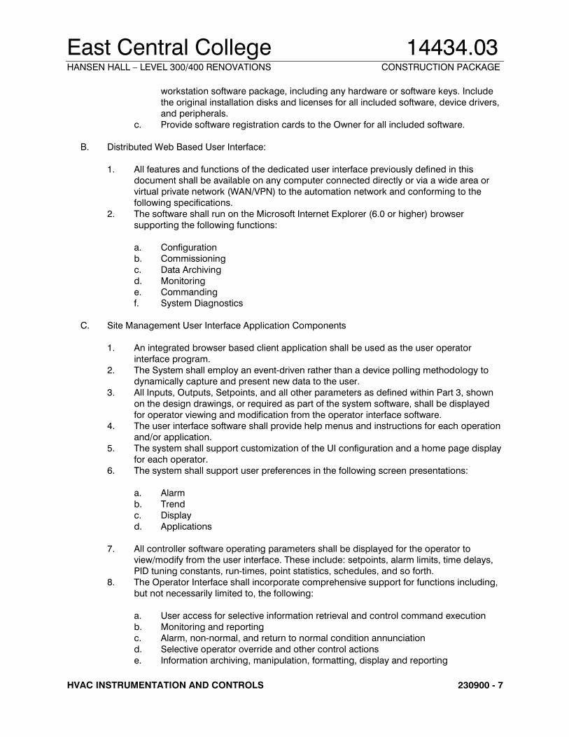
B. Distributed Web Based User Interface:
1. All features and functions of the dedicated user interface previously defined in this document shall be available on any computer connected directly or via a wide area or
virtual private network (WAN/VPN) to the automation network and conforming to the
following specifications.
2. The software shall run on the Microsoft Internet Explorer (6.0 or higher) browser
supporting the following functions:
a. Configuration
b. Commissioning
c. Data Archiving
d. Monitoring
e. Commanding f. System Diagnostics
C. Site Management User Interface Application Components
1. An integrated browser based client application shall be used as the user operator
interface program.
2. The System shall employ an event-driven rather than a device polling methodology to
dynamically capture and present new data to the user.
3. All Inputs, Outputs, Setpoints, and all other parameters as defined within Part 3, shown
on the design drawings, or required as part of the system software, shall be displayed
for operator viewing and modification from the operator interface software. 4. The user interface software shall provide help menus and instructions for each operation
and/or application.
5. The system shall support customization of the UI configuration and a home page display
for each operator.
6. The system shall support user preferences in the following screen presentations:
a. Alarm
b. Trend
c. Display
d. Applications
7. All controller software operating parameters shall be displayed for the operator to view/modify from the user interface. These include: setpoints, alarm limits, time delays,
PID tuning constants, run-times, point statistics, schedules, and so forth.
8. The Operator Interface shall incorporate comprehensive support for functions including,
but not necessarily limited to, the following:
a. User access for selective information retrieval and control command execution
b. Monitoring and reporting
c. Alarm, non-normal, and return to normal condition annunciation
d. Selective operator override and other control actions
e. Information archiving, manipulation, formatting, display and reporting
East Central College 14434.03 HANSEN HALL – LEVEL 300/400 RENOVATIONS CONSTRUCTION PACKAGE
HVAC INSTRUMENTATION AND CONTROLS 230900 - 8
f. BAS internal performance supervision and diagnostics
g. On-line access to user HELP menus
h. On-line access to current BAS as-built records and documentation
i. Means for the controlled re-programming, re-configuration of BAS operation and
for the manipulation of BAS database information in compliance with the
prevailing codes, approvals and regulations for individual BAS applications.
9. The system shall support a list of application programs configured by the users that are
called up by the following means:
a. The Tools Menu
b. Hyperlinks within the graphics displays
c. Key sequences
10. The operation of the control system shall be independent of the user interface, which
shall be used for operator communications only. Systems that rely on an operator
workstation to provide supervisory control over controller execution of the sequences of
operations or system communications shall not be acceptable.
11. Navigation Trees
a. The system will have the capability to display multiple navigation trees that will aid
the operator in navigating throughout all systems and points connected. At
minimum provide a tree that identifies all systems on the networks.
b. Provide the ability for the operator to add custom trees. The operator will be able
to define any logical grouping of systems or points and arrange them on the tree
in any order. It shall be possible to nest groups within other groups. Provide at
minimum 5 levels of nesting.
c. The navigation trees shall be “dockable” to other displays in the user interface
such as graphics. This means that the trees will appear as part of the display, but can be detached and then minimized to the Windows task bar or closed
altogether. A simple keystroke will reattach the navigation to the primary display
of the user interface.
12. Alarms
a. Alarms shall be routed directly from Network Automation Engines to PCs and
servers. It shall be possible for specific alarms from specific points to be routed to
specific PCs and servers. The alarm management portion of the user interface
shall, at the minimum, provide the following functions:
b. Log date and time of alarm occurrence.
c. Generate a “Pop-Up” window, with audible alarm, informing a user that an alarm has been received.
d. Allow a user, with the appropriate security level, to acknowledge, temporarily
silence, or discard an alarm.
e. Provide an audit trail on hard drive for alarms by recording user acknowledgment,
deletion, or disabling of an alarm. The audit trail shall include the name of the
user, the alarm, the action taken on the alarm, and a time/date stamp.
f. Provide the ability to direct alarms to an e-mail address or alphanumeric pager.
This must be provided in addition to the pop up window described above.
Systems that use e-mail and pagers as the exclusive means of annunciating alarms are not acceptable.
g. Any attribute of any object in the system may be designated to report an alarm.
East Central College 14434.03 HANSEN HALL – LEVEL 300/400 RENOVATIONS CONSTRUCTION PACKAGE
HVAC INSTRUMENTATION AND CONTROLS 230900 - 9
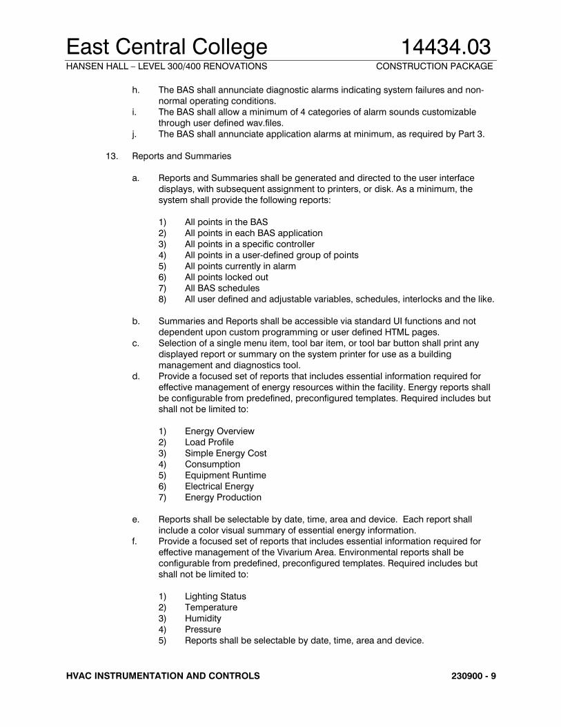
h. The BAS shall annunciate diagnostic alarms indicating system failures and non-
normal operating conditions.
i. The BAS shall allow a minimum of 4 categories of alarm sounds customizable
through user defined wav.files.
j. The BAS shall annunciate application alarms at minimum, as required by Part 3.
13. Reports and Summaries
a. Reports and Summaries shall be generated and directed to the user interface
displays, with subsequent assignment to printers, or disk. As a minimum, the
system shall provide the following reports:
1) All points in the BAS
2) All points in each BAS application
3) All points in a specific controller
4) All points in a user-defined group of points
5) All points currently in alarm
6) All points locked out
7) All BAS schedules 8) All user defined and adjustable variables, schedules, interlocks and the like.
b. Summaries and Reports shall be accessible via standard UI functions and not
dependent upon custom programming or user defined HTML pages.
c. Selection of a single menu item, tool bar item, or tool bar button shall print any
displayed report or summary on the system printer for use as a building
management and diagnostics tool.
d. Provide a focused set of reports that includes essential information required for
effective management of energy resources within the facility. Energy reports shall
be configurable from predefined, preconfigured templates. Required includes but shall not be limited to:
1) Energy Overview
2) Load Profile
3) Simple Energy Cost
4) Consumption
5) Equipment Runtime
6) Electrical Energy
7) Energy Production
e. Reports shall be selectable by date, time, area and device. Each report shall
include a color visual summary of essential energy information. f. Provide a focused set of reports that includes essential information required for
effective management of the Vivarium Area. Environmental reports shall be
configurable from predefined, preconfigured templates. Required includes but
shall not be limited to:
1) Lighting Status
2) Temperature
3) Humidity
4) Pressure
5) Reports shall be selectable by date, time, area and device.
East Central College 14434.03 HANSEN HALL – LEVEL 300/400 RENOVATIONS CONSTRUCTION PACKAGE
HVAC INSTRUMENTATION AND CONTROLS 230900 - 10
14. Schedules
a. A graphical display for time-of-day scheduling and override scheduling of building
operations shall be provided. At a minimum, the following functions shall be
provided:
1) Weekly schedules
2) Exception Schedules 3) Monthly calendars
b. Weekly schedules shall be provided for each group of equipment with a specific
time use schedule.
c. It shall be possible to define one or more exception schedules for each schedule
including references to calendars
d. Monthly calendars shall be provided that allow for simplified scheduling of
holidays and special days for a minimum of five years in advance. Holidays and
special days shall be user-selected with the pointing device or keyboard, and shall
automatically reschedule equipment operation as previously defined on the
exception schedules. e. Changes to schedules made from the User Interface shall directly modify the
Network Automation Engine schedule database.
f. Schedules and Calendars shall comply with ASHRAE SP135/2003 BACnet
Standard.
15. Password
a. Multiple-level password access protection shall be provided to allow the
user/manager to user interface control, display, and database manipulation
capabilities deemed appropriate for each user, based on an assigned password.
b. Each user shall have the following: a user name (accept 24 characters minimum), a password (accept 12 characters minimum), and access levels.
c. The system shall allow each user to change his or her password at will.
d. When entering or editing passwords, the system shall not echo the actual
characters for display on the monitor.
e. A minimum of five levels of access shall be supported individually or in any
6) Level 6 = All privileges, including Password Add/Modify
f. A minimum of 100 unique passwords shall be supported.
g. Operators shall be able to perform only those commands available for their
respective passwords. Display of menu selections shall be limited to only those
items defined for the access level of the password used to log-on.
h. The system shall automatically generate a report of log-on/log-off and system
activity for each user. Any action that results in a change in the operation or
configuration of the control system shall be recorded, including: modification of point values, schedules or history collection parameters, and all changes to the
East Central College 14434.03 HANSEN HALL – LEVEL 300/400 RENOVATIONS CONSTRUCTION PACKAGE
HVAC INSTRUMENTATION AND CONTROLS 230900 - 11
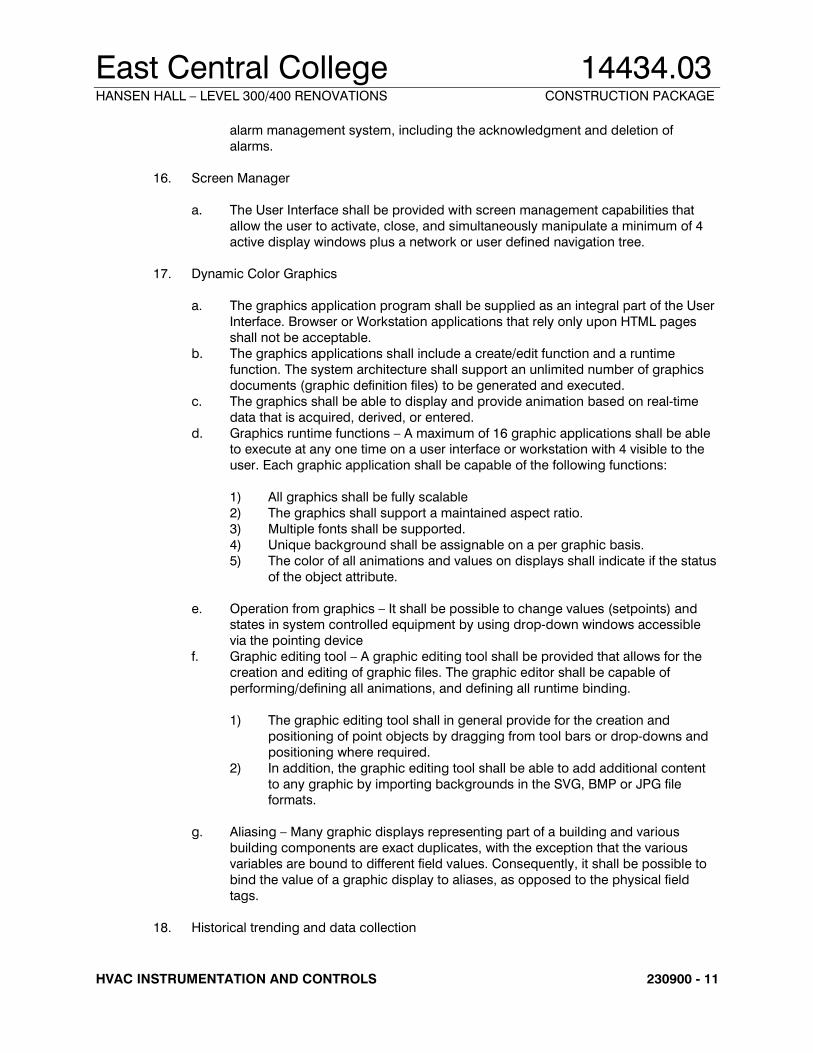
alarm management system, including the acknowledgment and deletion of
alarms.
16. Screen Manager
a. The User Interface shall be provided with screen management capabilities that
allow the user to activate, close, and simultaneously manipulate a minimum of 4
active display windows plus a network or user defined navigation tree.
17. Dynamic Color Graphics
a. The graphics application program shall be supplied as an integral part of the User
Interface. Browser or Workstation applications that rely only upon HTML pages
shall not be acceptable.
b. The graphics applications shall include a create/edit function and a runtime
function. The system architecture shall support an unlimited number of graphics
documents (graphic definition files) to be generated and executed.
c. The graphics shall be able to display and provide animation based on real-time
data that is acquired, derived, or entered.
d. Graphics runtime functions – A maximum of 16 graphic applications shall be able to execute at any one time on a user interface or workstation with 4 visible to the
user. Each graphic application shall be capable of the following functions:
1) All graphics shall be fully scalable
2) The graphics shall support a maintained aspect ratio.
3) Multiple fonts shall be supported.
4) Unique background shall be assignable on a per graphic basis.
5) The color of all animations and values on displays shall indicate if the status
of the object attribute.
e. Operation from graphics – It shall be possible to change values (setpoints) and states in system controlled equipment by using drop-down windows accessible
via the pointing device
f. Graphic editing tool – A graphic editing tool shall be provided that allows for the
creation and editing of graphic files. The graphic editor shall be capable of
performing/defining all animations, and defining all runtime binding.
1) The graphic editing tool shall in general provide for the creation and
positioning of point objects by dragging from tool bars or drop-downs and
positioning where required.
2) In addition, the graphic editing tool shall be able to add additional content
to any graphic by importing backgrounds in the SVG, BMP or JPG file formats.
g. Aliasing – Many graphic displays representing part of a building and various
building components are exact duplicates, with the exception that the various
variables are bound to different field values. Consequently, it shall be possible to
bind the value of a graphic display to aliases, as opposed to the physical field
tags.
18. Historical trending and data collection
East Central College 14434.03 HANSEN HALL – LEVEL 300/400 RENOVATIONS CONSTRUCTION PACKAGE
HVAC INSTRUMENTATION AND CONTROLS 230900 - 12
a. Each Automation Engine shall store trend and point history data for all analog and
digital inputs and outputs, as follows:
1) Any point, physical or calculated, may be designated for trending. Three
methods of collection shall be allowed: Defined time interval Upon a
change of value.
2) Each Automation Engine shall have the capability to store multiple samples for each physical point and software variable based upon available
memory, including an individual sample time/date stamp. Points may be
assigned to multiple history trends with different collection parameters.
b. Trend and change of value data shall be stored within the engine and uploaded to
a dedicated trend database or exported in a selectable data format via a provided
data export utility. Uploads to a dedicated database shall occur based upon one
of the following: user-defined interval, manual command, or when the trend
buffers are full. Exports shall be as requested by the user or on a time scheduled
basis.
c. The system shall provide a configurable data storage subsystem for the collection of historical data. Data can be stored in either Microsoft Access or SQL database
format.
19. Trend data viewing and analysis
a. Provide a trend viewing utility that shall have access to all database points.
b. It shall be possible to retrieve any historical database point for use in displays and
reports by specifying the point name and associated trend name.
c. The trend viewing utility shall have the capability to define trend study displays to
include multiple trends
d. Displays shall be able to be single or stacked graphs with on-line selectable display characteristics, such as ranging, color, and plot style.
e. Display magnitude and units shall both be selectable by the operator at any time
without reconfiguring the processing or collection of data. This is a zoom
capability.
f. Display magnitude shall automatically be scaled to show full graphic resolution of
the data being displayed.
g. Trend studies shall be capable of calculating and displaying calculated variables
including highest value, lowest value and time based accumulation.
h. The Display shall support the user’s ability to change colors, sample sizes, and
types of markers.
20. Software
a. Portable operator terminals shall support all controllers within the system on a
direct-connect communications basis.
b. When used to access First or Second Tier controllers, the portable operator
terminal shall utilize the standard operator workstation software, as previously
defined.
c. When used to access Application Specific Controllers, the portable operator
terminal shall utilize either the standard operator workstation software, as
previously defined, or controller-specific utility software.
East Central College 14434.03 HANSEN HALL – LEVEL 300/400 RENOVATIONS CONSTRUCTION PACKAGE
HVAC INSTRUMENTATION AND CONTROLS 230900 - 13
2.5 NETWORK AUTOMATION ENGINES
A. The Network Automation Engine (NAE) shall be a fully user-programmable, supervisory
controller. The NAE shall monitor the network of distributed application-specific controllers,
provide global strategy and direction, and communicate on a peer-to-peer basis with other
Network Automation Engines.
B. Automation network – The NAE shall reside on the automation network and shall support a subnet of system controllers.
C. Communications Ports – The NAE shall provide the following ports for operation of operator
Input/Output (I/O) devices, such as industry-standard computers, modems, and portable
operator’s terminals.
1. Two (2) USB port
2. Two (2) URS-232 serial data communication port
3. Two (2) RS-485 port
4. One (1) Ethernet port
D. Diagnostics – The NAE shall continuously perform self-diagnostics, communication diagnosis,
and diagnosis of all panel components. The Network Automation Engine shall provide both local and remote annunciation of any detected component failures, low battery conditions, or
repeated failures to establish communication.
E. Power Failure – In the event of the loss of normal power, The NAE shall continue to operate for
a user adjustable period of up to 10 minutes after which there shall be an orderly shutdown of
all programs to prevent the loss of database or operating system software.
1. During a loss of normal power, the control sequences shall go to the normal system
shutdown conditions. All critical configuration data shall be saved into Flash memory.
2. Upon restoration of normal power and after a minimum off-time delay, the controller shall
automatically resume full operation without manual intervention through a normal soft-start sequence.
2.6 CONTROLLERS
A. Provide a separate Controller for each major piece of HVAC equipment. Points used for
control loop reset such as outside air or space temperature are exempt from this requirement.
B. Building Controllers and Custom Application Controllers shall be selected to provide a
minimum of 15% spare I/O point capacity for each point type found at each location. If input
points are not universal, 15% of each type is required. If outputs are not universal, 15% of each
type is required. A minimum of one spare is required for each type of point used.
C. Future use of spare capacity shall require providing the field device, field wiring, points
database definition, and custom software. No additional Controller boards or point modules shall be required to implement use of these spare points.
2.7 INPUT DEVICES
East Central College 14434.03 HANSEN HALL – LEVEL 300/400 RENOVATIONS CONSTRUCTION PACKAGE
HVAC INSTRUMENTATION AND CONTROLS 230900 - 14
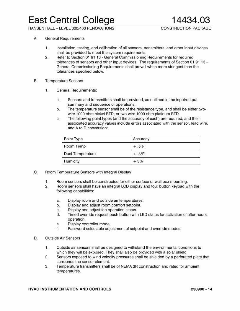
A. General Requirements
1. Installation, testing, and calibration of all sensors, transmitters, and other input devices
shall be provided to meet the system requirements.
2. Refer to Section 01 91 13 - General Commissioning Requirements for required
tolerances of sensors and other input devices. The requirements of Section 01 91 13 –
General Commissioning Requirements shall prevail when more stringent than the tolerances specified below.
B. Temperature Sensors
1. General Requirements:
a. Sensors and transmitters shall be provided, as outlined in the input/output
summary and sequence of operations.
b. The temperature sensor shall be of the resistance type, and shall be either two-
c. Thermal Effects: <+.033 F.S./Deg. F. over 40°F. to 100°F. (calibrated at 70°F.).
2. Standalone pressure transmitters shall be mounted in a bypass valve assembly panel.
The panel shall be constructed to NEMA 1 standards. The transmitter shall be installed in
East Central College 14434.03 HANSEN HALL – LEVEL 300/400 RENOVATIONS CONSTRUCTION PACKAGE
HVAC INSTRUMENTATION AND CONTROLS 230900 - 17
the panel with high and low connections piped and valved. Air bleed units, bypass
valves, and compression fittings shall be provided.
3. Acceptable manufacturers: Johnson Controls and Setra.
L. Power Monitoring Devices
1. Current Measurement (Amps)
a. Current measurement shall be by a combination current transformer and a current transducer. The current transformer shall be sized to reduce the full amperage of
the monitored circuit to a maximum 5 Amp signal, which will be converted to a 4-
20 mA DDC compatible signal for use by the Facility Management System.
b. Current Transformer – A split core current transformer shall be provided to monitor
motor amps.
1) Operating frequency – 50 - 400 Hz.
2) Insulation – 0.6 Kv class 10Kv BIL.
3) UL recognized.
4) Five amp secondary.
5) Select current ration as appropriate for application. 6) Acceptable manufacturers: Veris Industries.
c. Current Transducer – A current to voltage or current to mA transducer shall be
provided. The current transducer shall include:
1) 6X input over amp rating for AC inrushes of up to 120 amps.
2) Manufactured to UL 1244.
3) Accuracy: +.5%, Ripple +1%.
4) Minimum load resistance 30kOhm.
5) Input 0-20 Amps.
6) Output 4-20 mA. 7) Transducer shall be powered by a 24VDC regulated power supply (24 VDC
+5%).
8) Acceptable manufacturers: Veris Industries
M. Status and Safety Switches
1. General Requirements
a. Switches shall be provided to monitor equipment status, safety conditions, and
generate alarms at the BAS when a failure or abnormal condition occurs. Safety
switches shall be provided with two sets of contacts and shall be interlock wired to
shut down respective equipment.
2. Current Sensing Switches
a. The current sensing switch shall be self-powered with solid-state circuitry and a
dry contact output. It shall consist of a current transformer, a solid state current
sensing circuit, adjustable trip point, solid state switch, SPDT relay, and an LED
indicating the on or off status. A conductor of the load shall be passed through the
window of the device. It shall accept over-current up to twice its trip point range.
b. Current sensing switches shall be used for run status for fans, pumps, and other
East Central College 14434.03 HANSEN HALL – LEVEL 300/400 RENOVATIONS CONSTRUCTION PACKAGE
HVAC INSTRUMENTATION AND CONTROLS 230900 - 18
miscellaneous motor loads.
c. Current sensing switches shall be calibrated to show a positive run status only
when the motor is operating under load. A motor running with a broken belt or
coupling shall indicate a negative run status.
d. Acceptable manufacturers: Veris Industries
N. Air Filter Status Switches
1. Differential pressure switches used to monitor air filter status shall be of the automatic
reset type with SPDT contacts rated for 2 amps at 120VAC.
2. A complete installation kit shall be provided, including: static pressure tops, tubing,
fittings, and air filters.
3. Provide appropriate scale range and differential adjustment for intended service.
4. Acceptable manufacturers: Johnson Controls, Cleveland Controls
O. Air Flow Switches
1. Differential pressure flow switches shall be bellows actuated mercury switches or snap
acting micro-switches with appropriate scale range and differential adjustment for
intended service. 2. Acceptable manufacturers: Johnson Controls, Cleveland Controls
P. Air Pressure Safety Switches
1. Air pressure safety switches shall be of the manual reset type with SPDT contacts rated
for 2 amps at 120VAC.
2. Pressure range shall be adjustable with appropriate scale range and differential
adjustment for intended service.
3. Acceptable manufacturers: Johnson Controls, Cleveland Controls
Q. Low Temperature Limit Switches
1. The low temperature limit switch shall be of the manual reset type with Double Pole/Single Throw snap acting contacts rated for 16 amps at 120VAC.
2. The sensing element shall be a minimum of 15 feet in length and shall react to the
coldest 18-inch section. Element shall be mounted horizontally across duct in
accordance with manufacturers recommended installation procedures.
3. For large duct areas where the sensing element does not provide full coverage of the air
stream, additional switches shall be provided as required to provide full protection of the
air stream.
4. The low temperature limit switch shall be equal to Johnson Controls A70.
2.8 OUTPUT DEVICES
A. Actuators
1. General Requirements
a. Damper and valve actuators shall be electronic, as specified in the System
Description section.
East Central College 14434.03 HANSEN HALL – LEVEL 300/400 RENOVATIONS CONSTRUCTION PACKAGE
HVAC INSTRUMENTATION AND CONTROLS 230900 - 19
B. Electronic Damper Actuators
1. Electronic damper actuators shall be direct shaft mount.
2. Modulating and two-position actuators shall be provided as required by the sequence of
operations. Damper sections shall be sized Based on actuator manufacturer’s
recommendations for face velocity, differential pressure and damper type. The actuator
mounting arrangement and spring return feature shall permit normally open or normally closed positions of the dampers, as required. All actuators (except terminal units) shall
be furnished with mechanical spring return unless otherwise specified in the sequences
of operations. All actuators shall have external adjustable stops to limit the travel in either
direction, and a gear release to allow manual positioning.
3. Modulating actuators shall accept 24 VAC or VDC power supply, consume no more than
15 VA, and be UL listed. The control signal shall be 2-10 VDC or 4-20 mA, and the
actuator shall provide a clamp position feedback signal of 2-10 VDC. The feedback
signal shall be independent of the input signal and may be used to parallel other
actuators and provide true position indication. The feedback signal of one damper
actuator for each separately controlled damper shall be wired back to a terminal strip in the control panel for trouble-shooting purposes.
4. Two-position or open/closed actuators shall accept 24 or 120 VAC power supply and be
UL listed. Isolation, smoke, exhaust fan, and other dampers, as specified in the
sequence of operations, shall be furnished with adjustable end switches to indicate
open/closed position or be hard wired to start/stop associated fan. Two-position
actuators, as specified in sequences of operations as “quick acting,” shall move full
stroke within 20 seconds. All smoke damper actuators shall be quick acting.
5. Acceptable manufacturers: Johnson Controls, Mamac.
C. Control Dampers
1. The BAS Contractor shall furnish all automatic dampers except those provided with air
handling units. All automatic dampers shall be sized for the application by the BAS
Contractor or as specifically indicated on the Drawings.
2. All dampers used for throttling airflow shall be of the opposed blade type arranged for
normally open or normally closed operation, as required. The damper is to be sized so
that, when wide open, the pressure drop is a sufficient amount of its close-off pressure
drop to shift the characteristic curve to near linear.
3. All dampers used for two-position, open/close control shall be parallel blade type
arranged for normally open or closed operation, as required.
4. Damper frames and blades shall be constructed of either galvanized steel or aluminum. Maximum blade length in any section shall be 60”. Damper blades shall be 16-gauge
minimum and shall not exceed eight (8) inches in width. Damper frames shall be 16-
gauge minimum hat channel type with corner bracing. All damper bearings shall be
made of reinforced nylon, stainless steel or oil-impregnated bronze. Dampers shall be
tight closing, low leakage type, with synthetic elastomer seals on the blade edges and
flexible stainless steel side seals. Dampers of 48”x48” size shall not leak in excess of 8.0
cfm per square foot when closed against 4” w.g. static pressure when tested in
accordance with AMCA Std. 500.
5. Airfoil blade dampers of double skin construction with linkage out of the air stream shall be used whenever the damper face velocity exceeds 1500 FPM or system pressure
exceeds 2.5” w.g., but no more than 4000 FPM or 6” w.g. Acceptable manufacturers are
Johnson Controls D-7250 D-1250 or D-1300, Ruskin CD50, and Vent Products 5650.
6. One piece rolled blade dampers with exposed or concealed linkage may be used with
face velocities of 1500 FPM or below. Acceptable manufacturers are: Johnson Controls
East Central College 14434.03 HANSEN HALL – LEVEL 300/400 RENOVATIONS CONSTRUCTION PACKAGE
HVAC INSTRUMENTATION AND CONTROLS 230900 - 20
D-1600, Ruskin CD36, and Vent Products 5800.
7. Multiple section dampers may be jack-shafted to allow mounting of piston pneumatic
actuators and direct connect electronic actuators. Each end of the jackshaft shall receive
at least one actuator to reduce jackshaft twist.
D. Control Relays
1. Control Pilot Relays
a. Control pilot relays shall be of a modular plug-in design with retaining springs or
clips.
b. Mounting Bases shall be snap-mount.
c. DPDT, 3PDT, or 4PDT relays shall be provided, as appropriate for application.
d. Contacts shall be rated for 10 amps at 120VAC.
e. Relays shall have an integral indicator light and check button.
f. Acceptable manufacturers: Johnson Controls, Lectro
E. Electronic Signal Isolation Transducers
1. A signal isolation transducer shall be provided whenever an analog output signal from
the BAS is to be connected to an external control system as an input (such as a chiller control panel), or is to receive as an input signal from a remote system.
2. The signal isolation transducer shall provide ground plane isolation between systems.
3. Signals shall provide optical isolation between systems.
4. Acceptable manufacturers: Advanced Control Technologies
F. External Manual Override Stations
1. External manual override stations shall provide the following:
a. An integral HAND/OFF/AUTO switch shall override the controlled device pilot
relay.
b. A status input to the Facility Management System shall indicate whenever the switch is not in the automatic position.
c. A Status LED shall illuminate whenever the output is ON.
d. An Override LED shall illuminate whenever the HOA switch is in either the HAND
or OFF position.
e. Contacts shall be rated for a minimum of 1 amp at 24 VAC.
2.9 MISCELLANEOUS DEVICES
A. Variable Frequency Motor Speed Control Drives – See Section 230514 – Variable Frequency
Drives
B. Local Control Panels
1. All control panels shall be factory constructed, incorporating the BAS manufacturer’s standard designs and layouts. All control panels shall be UL inspected and listed as an
assembly and carry a UL 508 label listing compliance. Control panels shall be fully
enclosed, with perforated sub-panel, hinged door, and slotted flush latch.
2. In general, the control panels shall consist of the DDC controller(s), display module as
East Central College 14434.03 HANSEN HALL – LEVEL 300/400 RENOVATIONS CONSTRUCTION PACKAGE
HVAC INSTRUMENTATION AND CONTROLS 230900 - 21
specified and indicated on the plans, and I/O devices—such as relays, transducers, and
so forth—that are not required to be located external to the control panel due to function.
Where specified the display module shall be flush mounted in the panel face unless
otherwise noted.
3. All I/O connections on the DDC controller shall be provide via removable or fixed screw
terminals. 4. Low and line voltage wiring shall be segregated. All provided terminal strips and wiring
shall be UL listed, 300-volt service and provide adequate clearance for field wiring.
5. All wiring shall be neatly installed in plastic trays or tie-wrapped.
6. A convenience 120 VAC duplex receptacle shall be provided in each enclosure, fused
on/off power switch, and required transformers.
C. Power Supplies
1. DC power supplies shall be sized for the connected device load. Total rated load shall
not exceed 75% of the rated capacity of the power supply.
2. Input: 120 VAC +10%, 60Hz.
3. Output: 24 VDC. 4. Line Regulation: +0.05% for 10% line change.
5. Load Regulation: +0.05% for 50% load change.
6. Ripple and Noise: 1 mV rms, 5 mV peak to peak.
7. An appropriately sized fuse and fuse block shall be provided and located next to the
power supply.
8. A power disconnect switch shall be provided next to the power supply.
PART 3 - PERFORMANCE/EXECUTION
3.1 BAS SPECIFIC REQUIREMENTS
A. Graphic Displays
1. Provide a color graphic system flow diagram display for each system with all points as indicated on the point list. All terminal unit graphic displays shall be from a standard
design library.
2. User shall access the various system schematics via a graphical penetration scheme
and/or menu selection.
B. Custom Reports:
1. Provide custom reports as required for this project as directed by owner and defined in
the points list.
C. Actuation Type
1. All Mechanical Equipment:
a. Actuation of dampers to be Electric
3.2 INSTALLATION PRACTICES
East Central College 14434.03 HANSEN HALL – LEVEL 300/400 RENOVATIONS CONSTRUCTION PACKAGE
HVAC INSTRUMENTATION AND CONTROLS 230900 - 22
A. BAS Wiring
1. All conduit, wiring, accessories and wiring connections required for the installation of the
Building Management System, as herein specified, shall be provided by the BAS
Contractor unless specifically shown on the Electrical Drawings. All wiring shall comply
with the requirements of applicable portions of 26 05 19 – Building Wire & Cable and all
local and national electric codes, unless specified otherwise in this section. 2. All BAS wiring materials and installation methods shall comply with BAS manufacturer
recommendations.
3. The sizing, type and provision of cable, conduit, cable trays, and raceways shall be the
design responsibility of the BAS Contractor. If complications arise, however, due to the
incorrect selection of cable, cable trays, raceways and/or conduit by the BAS Contractor,
the Contractor shall be responsible for all costs incurred in replacing the selected
components.
4. Class 2 Wiring
a. All Class 2 (24VAC or less) wiring shall be installed in conduit unless otherwise specified.
b. Conduit is not required for Class 2 wiring in concealed accessible locations. Class
2 wiring not installed in conduit shall be supported every 5’ from the building
structure utilizing metal hangers designed for this application. Wiring shall be
installed parallel to the building structural lines. All wiring shall be installed in
accordance with local code requirements.
5. Class 2 signal wiring and 24VAC power can be run in the same conduit. Power wiring
120VAC and greater cannot share the same conduit with Class 2 signal wiring.
6. Provide for complete grounding of all applicable signal and communications cables, panels and equipment so as to ensure system integrity of operation. Ground cabling
and conduit at the panel terminations. Avoid grounding loops.
B. BAS Line Voltage Power Source
1. 120-volt AC circuits used for the Building Management System shall be taken from panel
boards and circuit breakers provided by 26 24 16 - Panelboards.
2. Circuits used for the BAS shall be dedicated to the BAS and shall not be used for any
other purposes.
3. DDC terminal unit controllers may use AC power from motor power circuits.
C. BAS Raceway
1. All wiring shall be installed in conduit or raceway except as noted elsewhere in this specification. Minimum control wiring conduit size 1/2”.
2. All conduits and raceways shall be installed level, plumb, at right angles to the building
lines and shall follow the contours of the surface to which they are attached.
3. Flexible Metal Conduit shall be used for vibration isolation and shall be limited to 3 feet in
length when terminating to vibrating equipment. Flexible Metal Conduit may be used
within partition walls. Flexible Metal Conduit shall be UL listed.
4. BAS conduit shall be blue in color. See Specification Section 26 05 53 for identification
for electrical systems.
D. Penetrations
East Central College 14434.03 HANSEN HALL – LEVEL 300/400 RENOVATIONS CONSTRUCTION PACKAGE
HVAC INSTRUMENTATION AND CONTROLS 230900 - 23
1. Provide fire stopping for all penetrations used by dedicated BAS conduits and raceways.
2. All openings in fire proofed or fire stopped components shall be closed by using
approved fire resistive sealant.
3. All wiring passing through penetrations, including walls shall be in conduit or enclosed
raceway.
4. Penetrations of floor slabs shall be by core drilling. All penetrations shall be plumb, true, and square.
E. BAS Identification Standards
1. Node Identification. All nodes shall be identified by a permanent label fastened to the
enclosure. Labels shall be suitable for the node location.
2. Cable types specified in Item A shall be color coded for easy identification and
troubleshooting.
F. BAS Panel Installation
1. The BAS contractor shall be responsible for coordinating panel locations with other
trades and electrical and mechanical contractors.
G. Input Devices
1. All Input devices shall be installed per the manufacturer recommendation
2. Locate components of the BAS in accessible local control panels wherever possible.
H. HVAC Input Devices – Genera1
1. All Input devices shall be installed per the manufacturer recommendation
2. Locate components of the BAS in accessible local control panels wherever possible.
3. The mechanical contractor shall install all in-line devices such as temperature wells,
pressure taps, airflow stations, etc.
4. Input Flow Measuring Devices shall be installed in strict compliance with ASME
guidelines affecting non-standard approach conditions. 5. Outside Air Sensors
a. Sensors shall be mounted on the North wall to minimize solar radiant heat impact
or located in a continuous intake flow adequate to monitor outside air conditions
accurately.
b. Sensors shall be installed with a rain proof, perforated cover.
6. Water Differential Pressure Sensors
a. Differential pressure transmitters used for flow measurement shall be sized to the
flow-sensing device.
b. Differential pressure transmitters shall be supplied with tee fittings and shut-off
valves in the high and low sensing pick-up lines. c. The transmitters shall be installed in an accessible location wherever possible.
7. Medium to High Differential Water Pressure Applications (Over 21” w.c.):
a. Air bleed units, bypass valves and compression fittings shall be provided.
East Central College 14434.03 HANSEN HALL – LEVEL 300/400 RENOVATIONS CONSTRUCTION PACKAGE
HVAC INSTRUMENTATION AND CONTROLS 230900 - 24
8. Building/Space Differential Air Pressure Applications (-1” to +1” w.c.):
a. Transmitter’s exterior sensing tip shall be installed with a shielded static air probe
to reduce pressure fluctuations caused by wind.
b. The interior tip shall be inconspicuous and located as shown on the drawings.
9. Duct Temperature Sensors:
a. Duct mount sensors shall mount in an electrical box through a hole in the duct and be positioned so as to be easily accessible for repair or replacement.
b. The sensors shall be insertion type and constructed as a complete assembly
including lock nut and mounting plate.
c. For ductwork greater in any dimension than 48 inches or where air temperature
stratification exists such as a mixed air plenum, utilize an averaging sensor.
d. The sensor shall be mounted to suitable supports using factory approved element
holders.
10. Space Sensors:
a. Shall be mounted per ADA requirements.
b. Provide lockable tamper-proof covers in public areas and/or where indicated on the plans.
11. Low Temperature Limit Switches:
a. Install on the discharge side of the first water or steam coil in the air stream.
b. Mount element horizontally across duct in a serpentine pattern insuring each
square foot of coil is protected by 1 foot of sensor.
c. For large duct areas where the sensing element does not provide full coverage of
the air stream, provide additional switches as required to provide full protection of
the air stream.
12. Air Differential Pressure Status Switches:
a. Install with static pressure tips, tubing, fittings, and air filter.
I. HVAC Output Devices
1. All output devices shall be installed per the manufacturer’s recommendation. The
mechanical contractor shall install all in-line devices such as control valves, dampers,
airflow stations, pressure wells, etc.
2. Actuators: All control actuators shall be sized capable of closing against the maximum
system shut-off pressure. The actuator shall modulate in a smooth fashion through the
entire stroke. When any pneumatic actuator is sequenced with another device, pilot
positioners shall be installed to allow for proper sequencing.
3. Control Dampers: Shall be opposed blade for modulating control of airflow. Parallel blade dampers shall be installed for two position applications.
4. Electronic Signal Isolation Transducers: Whenever an analog output signal from the
Building Management System is to be connected to an external control system as an
input (such as a chiller control panel), or is to receive as an input a signal from a remote
system, provide a signal isolation transducer. Signal isolation transducer shall provide
ground plane isolation between systems. Signals shall provide optical isolation between
East Central College 14434.03 HANSEN HALL – LEVEL 300/400 RENOVATIONS CONSTRUCTION PACKAGE
HVAC INSTRUMENTATION AND CONTROLS 230900 - 25
systems
3.3 TRAINING
A. The BAS contractor shall provide the following training services:
1. Two days of on-site orientation by a system technician who is fully knowledgeable of the
specific installation details of the project. This orientation shall, at a minimum, consist of
a review of the project as-built drawings, the BAS software layout and naming conventions, and a walk through of the facility to identify panel and device locations.
2. Two Tuitions for a Building Managers course at the local JCI Training Center.
3.4 SEQUENCE OF OPERATIONS
A. Ductless Split System (AC-1/CU-1) (Alternate Bid 3): Stand-alone space thermostat shall cycle
fan and associated condensing unit as required to maintain space temperature set point.
1. AC-1/CU-1: The ductless split system shall serve as backup to the primary cooling
source under alternate bid #3. The primary cooling source shall be a variable air
volume (VAV) air damper off of the existing rooftop unit. The set point for the AC-1/CU-1
shall be 3° F. (adjustable) higher than the cooling set point for the air terminal.
B. Existing Air Handling Unit (AHU-1):
1. Variable volume unit consists of a supply fan and DX coil. The supply fan is controlled
by a variable frequency drive. A static pressure sensor shall be located in the main
supply duct approximately 2/3 of the length from the supply fan discharge. The unit
shall be controlled through the BAS as follows:
a. Occupied Mode:
1) The supply fans shall operate continuously and the associated variable
frequency drive shall adjust the speed of the fan uniformly as required to
maintain the duct static pressure set point (adjustable). Static pressure set
point shall be reset using the Trim & Respond logic within the range of 0.15 in. w.g. (adjustable) to 3.0 in. w.g. (adjustable). When the fan is off the set
point shall be 0.5 in. w.g. (adjustable). While the fan is proven on, every
two minutes (adjustable), trim the set point by 0.04 in. w.g. (adjustable) if
there are two or fewer zone pressure requests. If there are more than two
zone pressure requests, respond by increasing the set point by 0.06 in.
w.g. (adjustable).
2) The existing outside air damper shall open to minimum set point (10%,
adjustable). The damper shall modulate as required to maintain the CO2
level set point of 1100 ppm (adjustable). CO2 sensor shall be located in
return air duct. 3) The existing relief air damper shall modulate as required to maintain
building differential set point of +0.1” w.g.(adjustable).
4) Cooling Mode: In the cooling mode, the DX coil shall modulate as required
to maintain supply air discharge temperature set point of 55° F.
(adjustable). Associated condensing unit shall operate per original
East Central College 14434.03 HANSEN HALL – LEVEL 300/400 RENOVATIONS CONSTRUCTION PACKAGE
HVAC INSTRUMENTATION AND CONTROLS 230900 - 26
sequence of operation.
5) Heating Mode: Cooling shall be disabled. Outside air and return air
dampers shall modulate to provide 55°F (adjustable) supply air. All heating
is at electric reheat coils at zone air terminals. See Variable Volume Air
Terminal Box sequence below.
6) An enthalpy based economizer shall be engaged whenever outdoor air conditions permit. In the economizer mode, excess outdoor air shall be
relieved through the motorized relief damper in the basement.
b. Unoccupied Mode:
1) Heating Mode: Supply fan shall cycle on along with reheat coils as required
to maintain a reduced space temperature of 65° F. (adjustable). Morning
warm up mode will begin one hour (adjustable) before the occupied mode is scheduled to begin. During the warm up mode, the following shall occur:
a) The supply fan shall operate continuously. The outside air damper
shall be fully closed, the return air damper shall be fully open. The
variable frequency drive shall operate in the occupied mode of
control.
b) The zone reheat coils will modulate to reach occupied set point.
c) Warm-up mode will end when the space temperature reaches
occupied set point. At this time, the unit shall be returned to the
occupied mode of control.
2) Cooling Mode: System is off and all controls are de-energized. Morning
cool down mode will begin one hour (adjustable) before the occupied
mode is scheduled to begin. During the cool down mode, the following
shall occur:
a) The supply fan shall operate continuously. The outside air damper
shall be fully closed, the return air damper shall be fully open. The
variable frequency drive shall operate in the occupied mode of
control.
b) The DX coil and associated condensing unit shall stage on as required to maintain a supply air discharge temperature set point of
55° F. (adjustable).
c) Cool down mode will end when the space temperature reaches
occupied set point. At this time, the unit shall be returned to the
occupied mode of control.
3) Safety Devices:
a) When mixed air temperature falls below 35° F. (adjustable), freezestat
shall shut down supply fan, close outside air damper, open return air
damper and signal an alarm.
b) When smoke is detected the Unit (including relief fan) will shut down.
c) When the AHU is in the occupied mode, at minimum air flow and duct static pressure rises 0.2” (adjustable) above set point, the
modulating air damper in all AT boxes in the unoccupied mode and
at zero air flow shall be overridden to modulate open to their
East Central College 14434.03 HANSEN HALL – LEVEL 300/400 RENOVATIONS CONSTRUCTION PACKAGE
HVAC INSTRUMENTATION AND CONTROLS 230900 - 27
minimum air flow. If duct static pressure rises to 0.4” (adjustable)
above set point, the BAS shall shut down the supply fan, close the
outside air damper, open the return air damper and signal an alarm.
C. Variable Volume Air Terminal Boxes (AT’s):
1. General: Air Terminal (AT) controller shall be supplied to the AT manufacturer for factory
mounting. 2. Each air terminal shall have a modulating air damper and modulating electric heating
coil. In the cooling mode, the air damper shall modulate as required to maintain space
set point temperature. In the heating mode, the air damper shall maintain the scheduled
heating airflow position and the electric heating coil shall modulate as required to
maintain the space set point temperature. Control of the air terminal shall be via a
remote temperature sensor with local set point adjustment and the following features:
a. Local space temperature adjustment with maximum/minimum limits set through
the BAS.
D. Electric Reheat Coils (EHC’s):
1. General: Controller shall be provided to control existing zone air damper and new electric reheat coil.
2. In the cooling mode, the air damper shall modulate as required to maintain space set
point temperature. In the heating mode, the air damper shall maintain the scheduled
heating airflow position and the electric heating coil shall modulate as required to
maintain the space set point temperature. Control of the damper and heating coil shall
be via a remote temperature sensor with local set point adjustment and the following
features:
a. Local space temperature adjustment with maximum/minimum limits set through
the BAS.
E. Exhaust Fan (EF-1):
1. Inline exhaust fan located above ceiling shall be controlled through the BAS via a remote
wall-mounted temperature sensor with local set point adjustment.
F. All existing components not listed in this specification shall be controlled per existing