36
Issued 12/03 Operating Instructions and Spare parts list EASY 1-S Powder Coating Equipment (MS01 / 02) E 0102 II (2) D
27EASY 1-S / EASY 2-S
Issu
ed
12/0
3
Operating Instructions and Spare parts list
EASY 1-S
Powder Coating Equipment
(MS01 / 02)
E
0102 II (2) D
28 EASY 1-S / EASY 2-S
Issu
ed
12/0
3
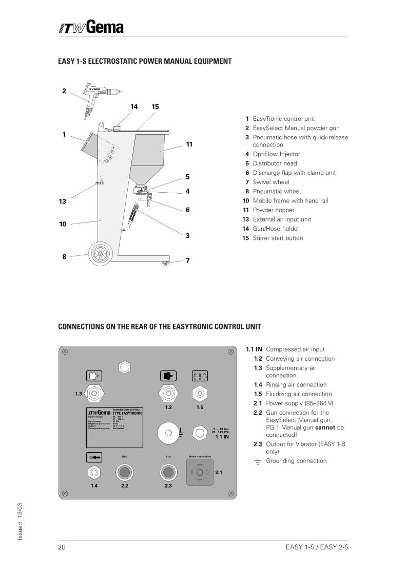
CONNECTIONS ON THE REAR OF THE EASYTRONIC CONTROL UNIT
1 EasyTronic control unit
2 EasySelect Manual powder gun3 Pneumatic hose with quick-release
connection
4 OptiFlow Injector
5 Distributor head
6 Discharge flap with clamp unit7 Swivel wheel
8 Pneumatic wheel
10 Mobile frame with hand rail
11 Powder hopper13 External air input unit
14 Gun/Hose holder
15 Stirrer start button
EASY 1-S ELECTROSTATIC POWER MANUAL EQUIPMENT
1.1 IN Compressed air input
1.2 Conveying air connection
1.3 Supplementary airconnection
1.4 Rinsing air connection1.5 Fluidizing air connection
2.1 Power supply (85–264 V)
2.2 Gun connection for theEasySelect Manual gun.PG 1 Manual gun cannot beconnected!
2.3 Output for Vibrator (EASY 1-Bonly)Grounding connection
Mains connectionAuxGun
1.1 IN
5 ... 10 bar73...145 PSI
1.4 2.2 2.3
2.1
1.3
1.2 1.5
Input voltage:
Input power:
Degree of protection:
Output:
Corresponding guns:
85 – 264 V
47 – 440 Hz
65 VA
IP 54
10 V 1,2 A
EasySelect
POWDER GUN CONTROL
TYPE EASYTRONIC
4
11
5
6
3
87
13
14
2
1
10
15
29EASY 1-S / EASY 2-S
Issu
ed
12/0
3
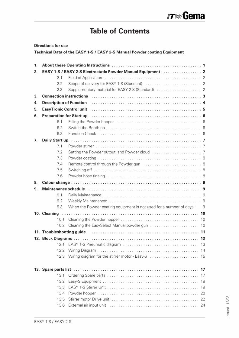
Table of Contents
Directions for use
Technical Data of the EASY 1-S / EASY 2-S Manual Powder coating Equipment
1. About these Operating Instructions . . . . . . . . . . . . . . . . . . . . . . . . . . . . . . . . . . . . . . . . 1
2. EASY 1-S / EASY 2-S Electrostatic Powder Manual Equipment . . . . . . . . . . . . . . . . . 2
2.1 Field of Application . . . . . . . . . . . . . . . . . . . . . . . . . . . . . . . . . . . . . . . . . . . 22.2 Scope of delivery for EASY 1-S (Standard) . . . . . . . . . . . . . . . . . . . . . . . . . 22.3 Supplementary material for EASY 2-S (Standard) . . . . . . . . . . . . . . . . . . . . 2
3. Connection instructions . . . . . . . . . . . . . . . . . . . . . . . . . . . . . . . . . . . . . . . . . . . . . . . . . 3
4. Description of Function . . . . . . . . . . . . . . . . . . . . . . . . . . . . . . . . . . . . . . . . . . . . . . . . . . 4
5. EasyTronic Control unit . . . . . . . . . . . . . . . . . . . . . . . . . . . . . . . . . . . . . . . . . . . . . . . . . . 5
6. Preparation for Start up . . . . . . . . . . . . . . . . . . . . . . . . . . . . . . . . . . . . . . . . . . . . . . . . . . 6
6.1 Filling the Powder hopper . . . . . . . . . . . . . . . . . . . . . . . . . . . . . . . . . . . . . . 66.2 Switch the Booth on . . . . . . . . . . . . . . . . . . . . . . . . . . . . . . . . . . . . . . . . . . 66.3 Function Check . . . . . . . . . . . . . . . . . . . . . . . . . . . . . . . . . . . . . . . . . . . . . . 6
7. Daily Start up . . . . . . . . . . . . . . . . . . . . . . . . . . . . . . . . . . . . . . . . . . . . . . . . . . . . . . . . . . 7
7.1 Powder stirrer . . . . . . . . . . . . . . . . . . . . . . . . . . . . . . . . . . . . . . . . . . . . . . . 77.2 Setting the Powder output, and Powder cloud . . . . . . . . . . . . . . . . . . . . . . 77.3 Powder coating . . . . . . . . . . . . . . . . . . . . . . . . . . . . . . . . . . . . . . . . . . . . . . 87.4 Remote control through the Powder gun . . . . . . . . . . . . . . . . . . . . . . . . . . 87.5 Switching off . . . . . . . . . . . . . . . . . . . . . . . . . . . . . . . . . . . . . . . . . . . . . . . . 87.6 Powder hose rinsing . . . . . . . . . . . . . . . . . . . . . . . . . . . . . . . . . . . . . . . . . . 8
8. Colour change . . . . . . . . . . . . . . . . . . . . . . . . . . . . . . . . . . . . . . . . . . . . . . . . . . . . . . . . . . 9
9. Maintenance schedule . . . . . . . . . . . . . . . . . . . . . . . . . . . . . . . . . . . . . . . . . . . . . . . . . . . 9
9.1 Daily Maintenance: . . . . . . . . . . . . . . . . . . . . . . . . . . . . . . . . . . . . . . . . . . . 99.2 Weekly Maintenance: . . . . . . . . . . . . . . . . . . . . . . . . . . . . . . . . . . . . . . . . . 99.3 When the Powder coating equipment is not used for a number of days: . . 9
10. Cleaning . . . . . . . . . . . . . . . . . . . . . . . . . . . . . . . . . . . . . . . . . . . . . . . . . . . . . . . . . . . . . 10
10.1 Cleaning the Powder hopper . . . . . . . . . . . . . . . . . . . . . . . . . . . . . . . . . . . 1010.2 Cleaning the EasySelect Manual powder gun . . . . . . . . . . . . . . . . . . . . . . 10
11. Troubleshooting guide . . . . . . . . . . . . . . . . . . . . . . . . . . . . . . . . . . . . . . . . . . . . . . . . . 11
12. Block Diagrams . . . . . . . . . . . . . . . . . . . . . . . . . . . . . . . . . . . . . . . . . . . . . . . . . . . . . . . . 13
12.1 EASY 1-S Pneumatic diagram . . . . . . . . . . . . . . . . . . . . . . . . . . . . . . . . . . 1312.2 Wiring Diagram . . . . . . . . . . . . . . . . . . . . . . . . . . . . . . . . . . . . . . . . . . . . . 1412.3 Wiring diagram for the stirrer motor - Easy-S . . . . . . . . . . . . . . . . . . . . . . 15
13. Spare parts list . . . . . . . . . . . . . . . . . . . . . . . . . . . . . . . . . . . . . . . . . . . . . . . . . . . . . . . . 17
13.1 Ordering Spare parts . . . . . . . . . . . . . . . . . . . . . . . . . . . . . . . . . . . . . . . . . 1713.2 Easy-S Equipment . . . . . . . . . . . . . . . . . . . . . . . . . . . . . . . . . . . . . . . . . . . 1813.3 EASY 1-S Stirrer Unit . . . . . . . . . . . . . . . . . . . . . . . . . . . . . . . . . . . . . . . . . 1913.4 Powder hopper . . . . . . . . . . . . . . . . . . . . . . . . . . . . . . . . . . . . . . . . . . . . . 2013.5 Stirrer motor Drive unit . . . . . . . . . . . . . . . . . . . . . . . . . . . . . . . . . . . . . . . 2213.6 External air input unit . . . . . . . . . . . . . . . . . . . . . . . . . . . . . . . . . . . . . . . . 24

30 EASY 1-S / EASY 2-S
Issu
ed
12/0
3
Safety regulations - H V. 2004
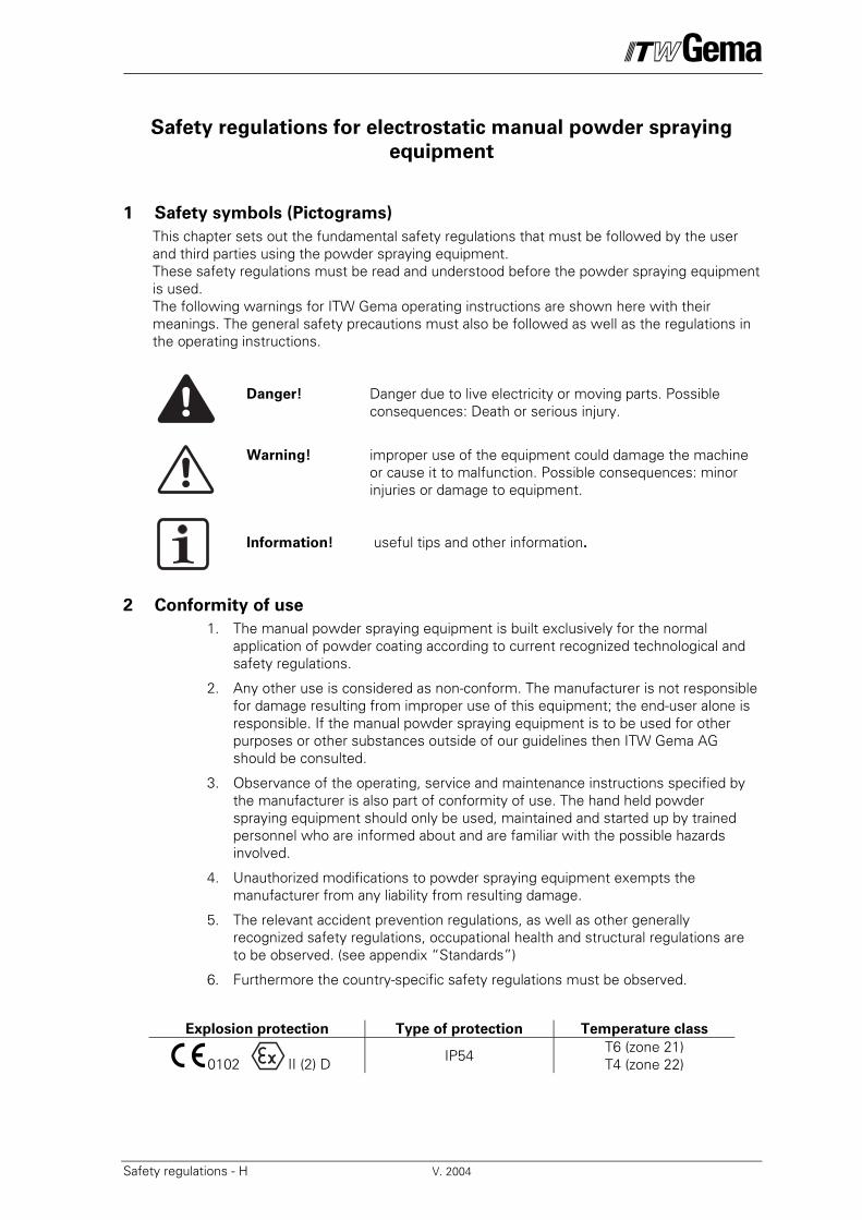
Safety regulations for electrostatic manual powder spraying
equipment
1 Safety symbols (Pictograms)
This chapter sets out the fundamental safety regulations that must be followed by the user and third parties using the powder spraying equipment. These safety regulations must be read and understood before the powder spraying equipment is used. The following warnings for ITW Gema operating instructions are shown here with their meanings. The general safety precautions must also be followed as well as the regulations in the operating instructions.
Danger! Danger due to live electricity or moving parts. Possible consequences: Death or serious injury.
Warning! improper use of the equipment could damage the machine
or cause it to malfunction. Possible consequences: minor injuries or damage to equipment.
Information! useful tips and other information.
2 Conformity of use
1. The manual powder spraying equipment is built exclusively for the normal application of powder coating according to current recognized technological and safety regulations.
2. Any other use is considered as non-conform. The manufacturer is not responsible for damage resulting from improper use of this equipment; the end-user alone is responsible. If the manual powder spraying equipment is to be used for other purposes or other substances outside of our guidelines then ITW Gema AG should be consulted.
3. Observance of the operating, service and maintenance instructions specified by the manufacturer is also part of conformity of use. The hand held powder spraying equipment should only be used, maintained and started up by trained personnel who are informed about and are familiar with the possible hazards involved.
4. Unauthorized modifications to powder spraying equipment exempts the manufacturer from any liability from resulting damage.
5. The relevant accident prevention regulations, as well as other generally recognized safety regulations, occupational health and structural regulations are to be observed. (see appendix “Standards”)
6. Furthermore the country-specific safety regulations must be observed.
Explosion protection Type of protection Temperature class
0102 II (2) D IP54 T6 (zone 21) T4 (zone 22)
V. 2004 Safety regulations - H
3 Safety Technical Information
3.1 General information
The powder spraying equipment from ITW Gema is safe to operate and is built according to the latest technological specifications. This equipment can be dangerous if it is not used for its specified purpose. It should also be noted that because of this there exists:
- A danger to life and limb of the user or third party.
- A danger of damage to the equipment and other machinery belonging to the user.
- A hazard to the efficient operation of the equipment.
1. The powder spraying equipment should only be started up and used once the operating instructions have been carefully studied.
2. Before every Start-up check the equipment for operational safety (regular servicing is essential)!
3. Safety regulations BGI 764 and VDE regulations DIN VDE 0147, Part 1, must be observed for safe operation.
4. Safety precautions specified by local legislation must be observed.
5. The plug must be disconnected before the machine is opened for repair.
6. Only original ITW-Gema replacement parts should be used, because the explosion protection will also be preserved that way. Damage caused by other parts is not covered by guarantee.
7. If ITW-Gema powder spraying equipment is used in conjunction with machinery from other manufacturers then their safety regulations must also be taken into account.
8. Caution must be exercised when working with a powder/air mixture! A powder/air mixture in the right concentration is flammable! No smoking during powder coating.
9. As a general rule for all powder spraying installations, persons with pacemakers should never enter high voltage areas or areas with electromagnetic fields. Persons with pacemakers should not enter areas with powder spraying installations!
Warning! We emphasize that the customer themselves is
responsible for safe operation of equipment. ITW-Gema
is in no way responsible for any resulting damages.
3.2 Safety conscious working
Each person responsible for the assembly, start-up, operation, service and repair of powder spraying equipment must have read and understood the operating instructions and the “Safety” chapter. The operator must ensure that the user has had the appropriate training for powder spraying equipment and is aware of the possible sources of danger.
The control devices for the spray guns must only be set up and used inside of the zone 22, and the spray guns should be used in the zone 21.
Safety regulations - H V. 2004
3.3 Individual safety regulations for the operating firm and/or operating
personnel
1. Any operating method which will negatively influence the technical safety of the powder spraying equipment is to be avoided.
2. The operator is under obligation to check the powder spraying equipment at least once a month for signs of external damage, defects or changes (including the operating characteristics) which could influence safety and to report them immediately.
3. The operator is obliged to check that the powder spraying equipment is only operated when in satisfactory condition.
4. As far as is necessary, the operating firm must ensure that the operating personnel wear protective clothing (e.g. facemasks).
5. The operating firm must guarantee cleanliness and an overview of the workplace with suitable instructions and checks in and around the powder spraying equipment.
3.4 Notes on special types of hazard
3.4.1 Power
High voltage equipment must not be opened - the plug must first be taken out – otherwise there is the danger of electric shock.
3.4.2 Powder
Powder/air mixtures can be ignited by sparks. There must be sufficient ventilation in the powder coating booth. Powder lying on the floor around the powder spraying device is a potentially dangerous source of slipping.
3.4.3 Static charges
Static charges can have the following consequences: Charges from people, electric shocks, sparking. Charges from objects must be avoided – see Earthing
3.4.4 Earthing
All electricity conducting parts and machinery found in the workplace (according to DIN VDE 0745, Part 102) must be earthed 1.5 m either side and 2.5 m around each booth opening. The earthing resistance of each piece of machinery must amount to 1 MΩ. The resistance must be tested on a regular basis. The condition of the machinery surroundings as well as the suspension gear must ensure that the machinery remains earthed. If the earthing of the machinery includes the suspension arrangements then these this must constantly be kept clean in order to keep the necessary conductivity. The appropriate measuring devices must be kept ready in the workplace in order to carry out the testing.
3.4.5 Compressed air
When there are to be longer pauses or stand-still times between working then the powder spraying equipment should be drained of compressed air. There is a danger of injury when pneumatic hoses are damaged and from the uncontrolled release and improper use of compressed air.
3.5 Prohibition of unauthorized conversions and modifications to equipment
All unauthorized conversions and modifications to powder spraying equipment are forbidden for safety reasons. The powder spraying equipment should not be used if damaged, the faulty part must be immediately replaced or repaired. Only original ITW-Gema replacement parts should be used. Damage caused by other parts is not covered by guarantee. Repairs must only be carried out by specialists or in ITW-Gema workshops. Unauthorized modifications can lead to personal injury and damage to machinery. The ITW Gema AG guarantee would no longer be valid.
V. 2004 Safety regulations - H
4 Safety requirements for electrostatic powder coating
1. This equipment is dangerous if the instructions in this operating manual are not followed.
2. All electrostatic conductive parts and in particular the machinery, within 5m of the coating equipment must be earthed.
3. The floor of the coating area must conduct electricity (normal concrete is generally conductive).
4. The operating personnel must wear electricity conducting footwear (e.g. leather soles).
5. The operating personnel should hold the gun with bare hands. If gloves are worn, these must also conduct electricity.
6. The supplied earthing cable (green/ yellow) must be connected to the earthing screw of the electrostatic powder spraying hand appliance. The earthing cable must have a good metallic connection with the coating booth, the recovery unit and the conveyor chain and with the suspension arrangement of the objects.
7. The electricity and powder supply to the hand guns must be set up so that they are fully protected against heat and chemical damage.
8. The powder coating device may only be switched on, once the booth has been started up. If the booth cuts out then the powder coating device must be switched off.
9. The earthing of all electricity conducting devices (e.g. hooks, conveyor chains) must be checked on a weekly basis. The earthing resistance must amount to ≤ 1 MΩ.
10. The control device must be switched off if the hand gun is cleaned or the nozzle is changed. The control device is also to be switched off when filling powder, so that ex atmosphere is not produced unnecessarily.
11. When working with cleaning agents there may be a risk of hazardous fumes. The manufactures information must be observed when using such cleaning agents.
12. The manufacturers instructions and the applicable environmental requirements must be observed when disposing of powder lacquer and cleaning agents.
13. If any part of the spray gun is damaged (broken parts, tears) or missing then it should not be used.
14. For your own safety, only use accessories and attachments listed in the operating instructions. The use of other parts can lead to risk of injury. Only original ITW-Gema replacement parts should be used.
15. Repairs must only be carried out by specialists and under no circumstances should they be carried out in the operating area. All unauthorized conversions and modifications may lead to injury or damage to machinery. The former protection must not be reduced.
16. Conditions leading to dangerous levels of dust concentration in the powder spraying booths or in the powder spraying areas must be avoided. There must be sufficient technical ventilation available, to prevent a dust concentration of more than 50% of the lower explosion limit (UEG) (UEG = max. permissible powder/air concentration) If the UEG is not known then a value of 20 g/m3 should be used.
Safety regulations - H V. 2004
5 A summary of the rules and regulations
The following is a list of relevant rules and regulations which are to be observed:
5.1 Guidelines and Regulations, German professional association
BGV A1 General Regulations. BGV A2 Electrical equipment and material. BGI764 Electrostatic coating BGR132 Guidelines for the avoidance of the dangers of ignition due to electrostatic
charging (Guideline “Static Electricity”) VDMA 24371 Guidelines for electrostatic coating with synthetic powder 1)
- Part 1 General requirements. - Part 2 Examples of use.
5.2 Leaflets
ZH 1/310 Leaflet on the use of tools in locations where there is danger of explosion. 1)
5.3 European Standards EN
RL94/9/EG The approximation of the laws of the Member States relating to apparatus and safety systems for their intended use in potentially explosive atmospheres
EN 292-1 EN 292-2 Machine safety 2)
EN 50 014 to EN 50
020 identical DIN VDE
0170/0171
Electrical equipment for locations where there is danger of explosion 3)
EN 50 050 Electrical apparatus for potentially explosive atmospheres - Electrostatic hand-held spraying equipment 2)
EN 50 053 Part 2 Requirements for the selection, installation and use of electrostatic spraying equipment for flammable materials - Hand-held electrostatic powder spray guns 2)
PR EN 12981 Coating plants - Spray booths for application of organic powder coating material - Safety requirements
EN 60529 identical DIN 40050
IP-Type protection: contact, foreign bodies and water protection for electrical equipment. 2)
EN 60 204 identical DIN VDE 0113
VDE Regulations for the setting up of high-voltage electrical machine tools and processing machines with nominal voltages up to 1000 V 3)
5.4 VDE (Association of German Engineers) Regulations
DIN VDE 0100 Regulations for setting-up high voltage equipment with nominal voltages up to 1000 V. 4)
DIN VDE 0105
Part 1
Part 4
VDE Regulations for the operation of high voltage equipment. 4) General regulations. Supplementary definitions for stationary electrical spraying equipment.
DIN VDE 0147
Part 1
Setting up stationary electrostatic spraying equipment 4)
DIN VDE 0165 Setting up electrical equipment in locations where there is a danger of explosion. 4)
Source:
1) Carl Heymanns Verlag KG, Luxemburger Strasse 449, 5000 Köln 41, or from the appropriate employers association.
2) Beuth Verlag GmbH, Burgrafenstrasse 4, 1000 Berlin 30 3) Generalsecretariat, Rue Bréderode 2, B-1000 Brüssel, or the appropriate national committee. 4) VDE Verlag GmbH, , Bismarckstrasse 33, 1000 Berlin 12
32 EASY 1-S / EASY 2-S
Issu
ed
12/0
3
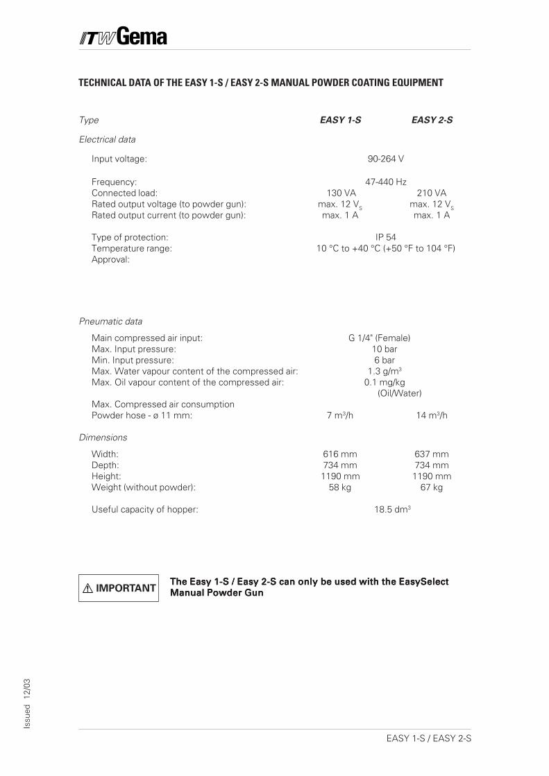
TECHNICAL DATA OF THE EASY 1-S / EASY 2-S MANUAL POWDER COATING EQUIPMENT
Type EASY 1-S EASY 2-S
Electrical data
Input voltage: 90-264 V
Frequency: 47-440 HzConnected load: 130 VA 210 VARated output voltage (to powder gun): max. 12 VS max. 12 VS
Rated output current (to powder gun): max. 1 A max. 1 A
Type of protection: IP 54Temperature range: 10 °C to +40 °C (+50 °F to 104 °F)Approval:
Pneumatic data
Main compressed air input: G 1/4" (Female)Max. Input pressure: 10 barMin. Input pressure: 6 barMax. Water vapour content of the compressed air: 1.3 g/m3
Max. Oil vapour content of the compressed air: 0.1 mg/kg (Oil/Water)
Max. Compressed air consumptionPowder hose - ø 11 mm: 7 m3/h 14 m3/h
Dimensions
Width: 616 mm 637 mmDepth: 734 mm 734 mmHeight: 1190 mm 1190 mmWeight (without powder): 58 kg 67 kg
Useful capacity of hopper: 18.5 dm3
The Easy 1-S / Easy 2-S can only be used with the EasySelectThe Easy 1-S / Easy 2-S can only be used with the EasySelectThe Easy 1-S / Easy 2-S can only be used with the EasySelectThe Easy 1-S / Easy 2-S can only be used with the EasySelectThe Easy 1-S / Easy 2-S can only be used with the EasySelectManual Powder GunManual Powder GunManual Powder GunManual Powder GunManual Powder GunIMPORTANT
1EASY 1-S / EASY 2-S
Issu
ed
12/0
3
1. ABOUT THESE OPERATING INSTRUCTIONS
These operating instructions contain all the important information whichis required to operate the EASY powder coating equipment. It will guideyou safely through the installation stage, give you information to con-vert your EASY 1 system to an EASY 2 system, also notes and tips forthe optimum use of your new powder coating system.The information about the functioning of the individual system compo-nents - EasyTronic powder gun control, EasySelect manual powder gunor OptiFlow powder injector will be found in the respective accompany-ing documentation.
2 EASY 1-S / EASY 2-S
Issu
ed
12/0
3
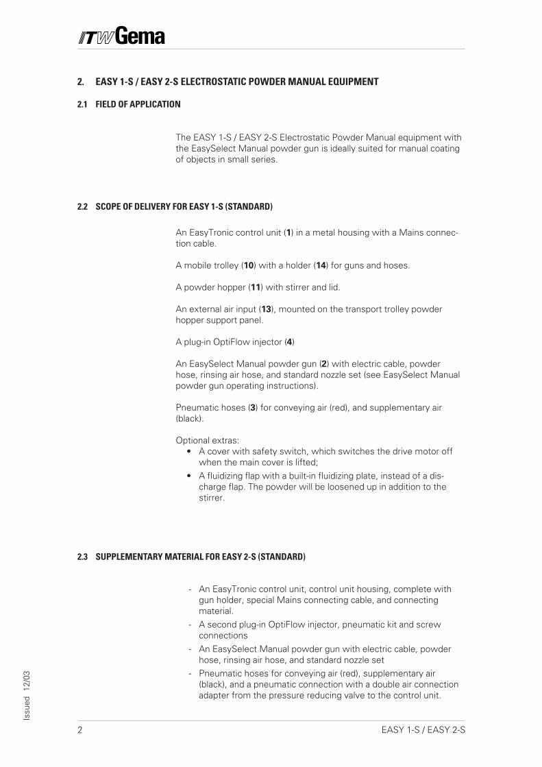
2. EASY 1-S / EASY 2-S ELECTROSTATIC POWDER MANUAL EQUIPMENT
2.1 FIELD OF APPLICATION
The EASY 1-S / EASY 2-S Electrostatic Powder Manual equipment withthe EasySelect Manual powder gun is ideally suited for manual coatingof objects in small series.
2.2 SCOPE OF DELIVERY FOR EASY 1-S (STANDARD)
An EasyTronic control unit (1) in a metal housing with a Mains connec-tion cable.
A mobile trolley (10) with a holder (14) for guns and hoses.
A powder hopper (11) with stirrer and lid.
An external air input (13), mounted on the transport trolley powderhopper support panel.
A plug-in OptiFlow injector (4)
An EasySelect Manual powder gun (2) with electric cable, powderhose, rinsing air hose, and standard nozzle set (see EasySelect Manualpowder gun operating instructions).
Pneumatic hoses (3) for conveying air (red), and supplementary air(black).
Optional extras:• A cover with safety switch, which switches the drive motor off
when the main cover is lifted;• A fluidizing flap with a built-in fluidizing plate, instead of a dis-
charge flap. The powder will be loosened up in addition to thestirrer.
2.3 SUPPLEMENTARY MATERIAL FOR EASY 2-S (STANDARD)
- An EasyTronic control unit, control unit housing, complete withgun holder, special Mains connecting cable, and connectingmaterial.
- A second plug-in OptiFlow injector, pneumatic kit and screwconnections
- An EasySelect Manual powder gun with electric cable, powderhose, rinsing air hose, and standard nozzle set
- Pneumatic hoses for conveying air (red), supplementary air(black), and a pneumatic connection with a double air connectionadapter from the pressure reducing valve to the control unit.
3EASY 1-S / EASY 2-S
Issu
ed
12/0
3
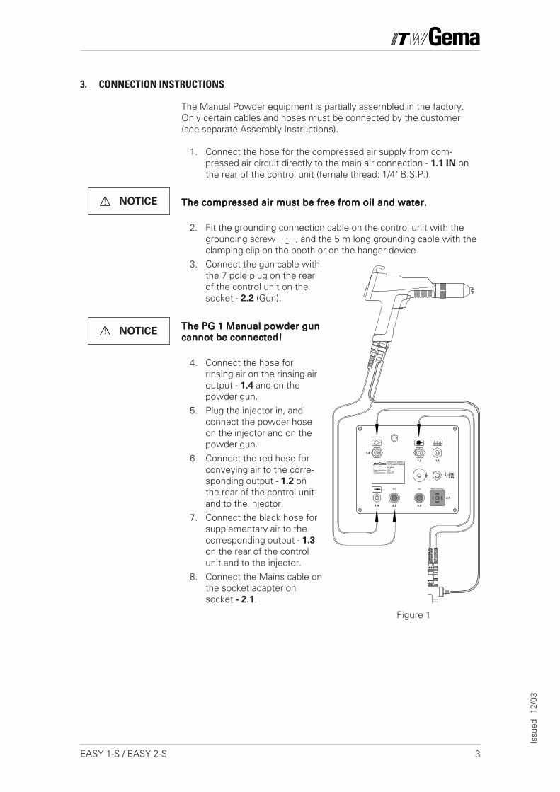
Figure 1
3. CONNECTION INSTRUCTIONS
The Manual Powder equipment is partially assembled in the factory.Only certain cables and hoses must be connected by the customer(see separate Assembly Instructions).
1. Connect the hose for the compressed air supply from com-pressed air circuit directly to the main air connection - 1.1 IN onthe rear of the control unit (female thread: 1/4" B.S.P.).
The compressed air must be free from oil and water.The compressed air must be free from oil and water.The compressed air must be free from oil and water.The compressed air must be free from oil and water.The compressed air must be free from oil and water.
2. Fit the grounding connection cable on the control unit with thegrounding screw , and the 5 m long grounding cable with theclamping clip on the booth or on the hanger device.
3. Connect the gun cable withthe 7 pole plug on the rearof the control unit on thesocket - 2.2 (Gun).
The PG 1 Manual powder gunThe PG 1 Manual powder gunThe PG 1 Manual powder gunThe PG 1 Manual powder gunThe PG 1 Manual powder guncannot be connected!cannot be connected!cannot be connected!cannot be connected!cannot be connected!
4. Connect the hose forrinsing air on the rinsing airoutput - 1.4 and on thepowder gun.
5. Plug the injector in, andconnect the powder hoseon the injector and on thepowder gun.
6. Connect the red hose forconveying air to the corre-sponding output - 1.2 onthe rear of the control unitand to the injector.
7. Connect the black hose forsupplementary air to thecorresponding output - 1.3
on the rear of the controlunit and to the injector.
8. Connect the Mains cable onthe socket adapter onsocket - 2.1.
NOTICE
NOTICE
Mains connectionAuxGun
1.1 IN
5 ... 10 bar73...145 PSI
1.4 2.2 2.3
2.1
1.3
1.2 1.5
Input voltage:
Input power:
Degree of protection:
Output:
Corresponding guns:
85 – 264 V
47 – 440 Hz
65 VA
IP 54
10 V 1,2 A
EasySelect
POWDER GUN CONTROL
TYPE EASYTRONIC
4 EASY 1-S / EASY 2-S
Issu
ed
12/0
3
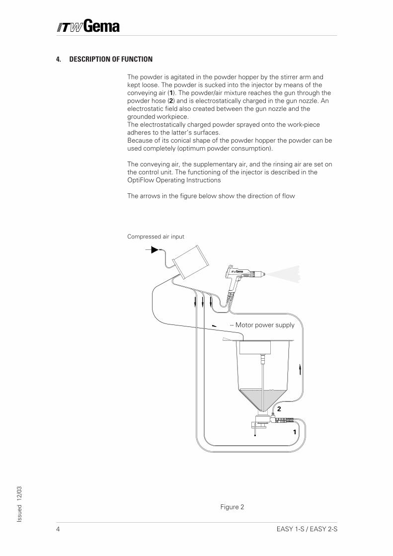
Figure 2
4. DESCRIPTION OF FUNCTION
The powder is agitated in the powder hopper by the stirrer arm andkept loose. The powder is sucked into the injector by means of theconveying air (1). The powder/air mixture reaches the gun through thepowder hose (2) and is electrostatically charged in the gun nozzle. Anelectrostatic field also created between the gun nozzle and thegrounded workpiece.The electrostatically charged powder sprayed onto the work-pieceadheres to the latter’s surfaces.Because of its conical shape of the powder hopper the powder can beused completely (optimum powder consumption).
The conveying air, the supplementary air, and the rinsing air are set onthe control unit. The functioning of the injector is described in theOptiFlow Operating Instructions
The arrows in the figure below show the direction of flow
Compressed air input
-- Motor power supply
2
1
5EASY 1-S / EASY 2-S
Issu
ed
12/0
3
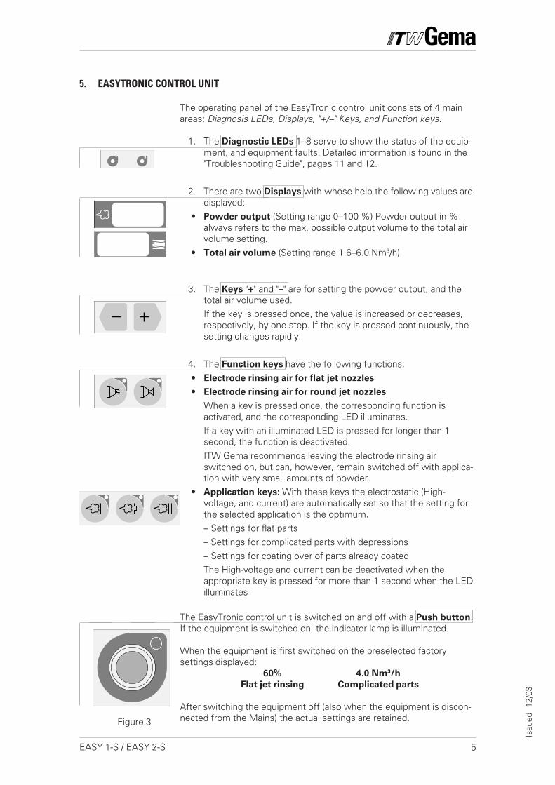
The operating panel of the EasyTronic control unit consists of 4 mainareas: Diagnosis LEDs, Displays, "+/–" Keys, and Function keys.
1. The Diagnostic LEDs 1–8 serve to show the status of the equip-ment, and equipment faults. Detailed information is found in the"Troubleshooting Guide", pages 11 and 12.
2. There are two Displays with whose help the following values aredisplayed:
• Powder output (Setting range 0–100 %) Powder output in %always refers to the max. possible output volume to the total airvolume setting.
• Total air volume (Setting range 1.6–6.0 Nm3/h)
3. The Keys "+" and "–" are for setting the powder output, and thetotal air volume used.If the key is pressed once, the value is increased or decreases,respectively, by one step. If the key is pressed continuously, thesetting changes rapidly.
4. The Function keys have the following functions:• Electrode rinsing air for flat jet nozzles
• Electrode rinsing air for round jet nozzles
When a key is pressed once, the corresponding function isactivated, and the corresponding LED illuminates.If a key with an illuminated LED is pressed for longer than 1second, the function is deactivated.ITW Gema recommends leaving the electrode rinsing airswitched on, but can, however, remain switched off with applica-tion with very small amounts of powder.
• Application keys: With these keys the electrostatic (High-voltage, and current) are automatically set so that the setting forthe selected application is the optimum.– Settings for flat parts– Settings for complicated parts with depressions– Settings for coating over of parts already coatedThe High-voltage and current can be deactivated when theappropriate key is pressed for more than 1 second when the LEDilluminates
The EasyTronic control unit is switched on and off with a Push button.If the equipment is switched on, the indicator lamp is illuminated.
When the equipment is first switched on the preselected factorysettings displayed:
60% 4.0 Nm3/h
Flat jet rinsing Complicated parts
After switching the equipment off (also when the equipment is discon-nected from the Mains) the actual settings are retained.
5. EASYTRONIC CONTROL UNIT
Figure 3
6 EASY 1-S / EASY 2-S
Issu
ed
12/0
3
6. PREPARATION FOR START UP
6.1 FILLING THE POWDER HOPPER
Switch the powder coating booth on according to the operatinginstructions.
6.2 SWITCH THE BOOTH ON
6.3 FUNCTION CHECK
1. Press the main switch on the control unit. The indicator lamp inthe switch illuminates.The equipment carries out the calibration automatically. Anincrease in sound can be heard inside the control unit. Bothdisplays show 888. The equipment is ready for operation after notmore than 20 seconds and switches to the factory settings.
2. Take the powder gun in the hand and point at a grounded objectin the booth, distance approx. 20 cm.
3. Press the gun trigger.The LED No. 8 illuminates. The High-voltage is switched on andpowder is conveyed.
If all tests are positive, the control unit, and the powder gun are readyfor operation. If one of the functions is not operating as expected,check this in the "Troubleshooting Guide", on pages 11 and 12.
1. Open the hinged flap of the hopper cover. (Do not fill with themain cover open as it may be difficult to fit the stirrer arm into thecorrect operating position).
2. Pour the powder into the hopper. Maximum filling level of thepowder is marked on the inside of the hopper (useful capacity:approx. 18.5 dm3 powder).
3. Close the hinged flap of the hopper cover.4. Press the push button on the stirrer cover, the stirrer starts up.
7EASY 1-S / EASY 2-S
Issu
ed
12/0
3
7. DAILY START UP
7.1 POWDER STIRRERAfter the trigger is released the stirred motor continues to run forapproximately 20 seconds. The cover should only be opened afterthe stirrer arm has come to a standstill!
The stirrer motor switches off immediately, as soon as the main coveris lifted.
7.2 SETTING THE POWDER OUTPUT, AND POWDER CLOUD
The powder output is dependent on the powder, and the setting of thetotal air volume.
1. Switch on the control unit2. Set the total air volume (For further information see the OptiFlow
Operating Instructions)The total air volume is dependent on the powder hose length, thenumber of turns of the hose, the hose diameter, and the object tobe coated.The value set for the total air volume can be left as it is, as longas the same powder hose is used. If the hose length and/or thehose diameter are changed, then the total air volume must bereset.
3. Select the powder output volume according to the desired coat-ing thickness.The selection takes place with the aid of the keys + and – eitheron the control unit or on the rear of the powder gun.To start, a standard setting of 60% is recommended. The total airvolume is maintained constant automatically.
4. Check the fluidizing of the powder5. Point the powder gun into the booth and press the powder gun
trigger6. Select the correct electrode rinsing
When using flat jet nozzles:
- Press the key with the corresponding symbol . The LED of thecorresponding key illuminates.When using round jet nozzles with air rinsed deflector plates:
- Press the key with the corresponding symbol . The LED of thecorresponding key illuminates.
(continued)
SET TOTAL AIRVOLUME
SELECT POWDEROUTPUT VOLUME
SELECT ELECTRODERINSING
CAUTION
8 EASY 1-S / EASY 2-S
Issu
ed
12/0
3
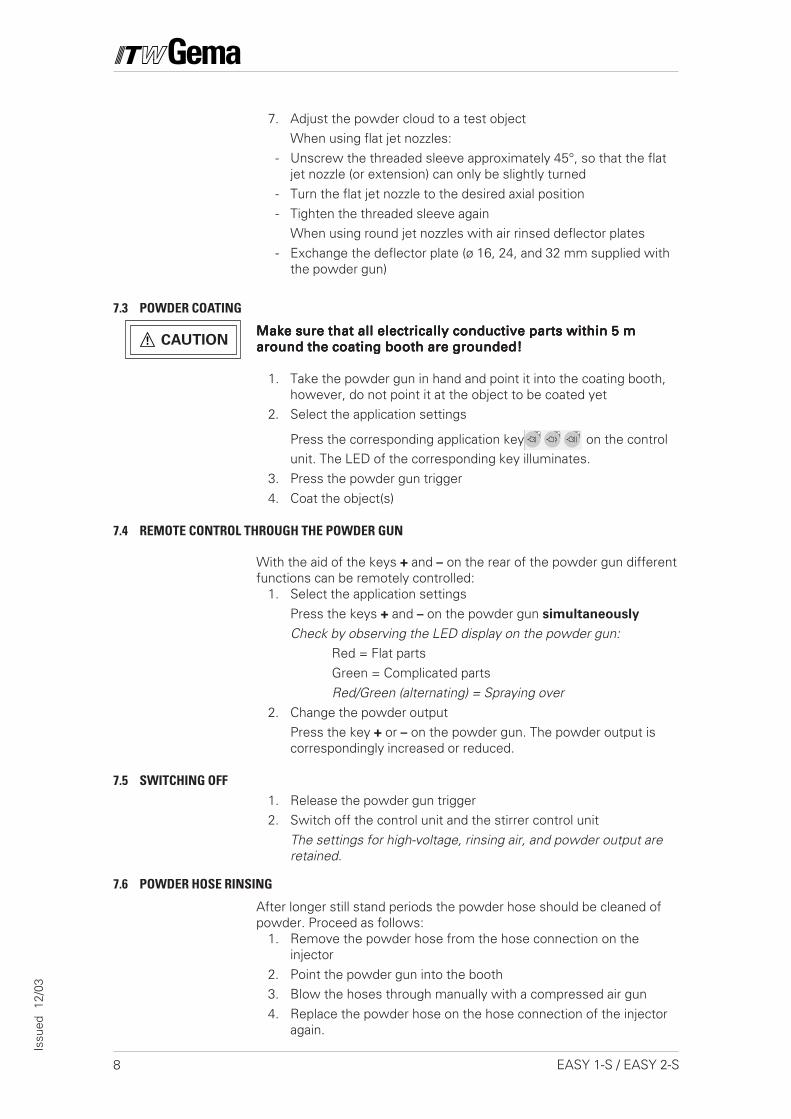
7.3 POWDER COATING
Make sure that all electrically conductive parts within 5 mMake sure that all electrically conductive parts within 5 mMake sure that all electrically conductive parts within 5 mMake sure that all electrically conductive parts within 5 mMake sure that all electrically conductive parts within 5 maround the coating booth are grounded!around the coating booth are grounded!around the coating booth are grounded!around the coating booth are grounded!around the coating booth are grounded!
1. Take the powder gun in hand and point it into the coating booth,however, do not point it at the object to be coated yet
2. Select the application settings
Press the corresponding application key on the controlunit. The LED of the corresponding key illuminates.
3. Press the powder gun trigger4. Coat the object(s)
7.5 SWITCHING OFF1. Release the powder gun trigger2. Switch off the control unit and the stirrer control unit
The settings for high-voltage, rinsing air, and powder output areretained.
7.6 POWDER HOSE RINSING
After longer still stand periods the powder hose should be cleaned ofpowder. Proceed as follows:
1. Remove the powder hose from the hose connection on theinjector
2. Point the powder gun into the booth3. Blow the hoses through manually with a compressed air gun4. Replace the powder hose on the hose connection of the injector
again.
7. Adjust the powder cloud to a test objectWhen using flat jet nozzles:
- Unscrew the threaded sleeve approximately 45°, so that the flatjet nozzle (or extension) can only be slightly turned
- Turn the flat jet nozzle to the desired axial position- Tighten the threaded sleeve again
When using round jet nozzles with air rinsed deflector plates- Exchange the deflector plate (ø 16, 24, and 32 mm supplied with
the powder gun)
7.4 REMOTE CONTROL THROUGH THE POWDER GUN
With the aid of the keys + and – on the rear of the powder gun differentfunctions can be remotely controlled:
1. Select the application settingsPress the keys + and – on the powder gun simultaneously
Check by observing the LED display on the powder gun:Red = Flat partsGreen = Complicated partsRed/Green (alternating) = Spraying over
2. Change the powder outputPress the key + or – on the powder gun. The powder output iscorrespondingly increased or reduced.
CAUTION
9EASY 1-S / EASY 2-S
Issu
ed
12/0
3
8. COLOUR CHANGE
1. Empty and clean the powder hopper (see page 10)2. Blow out the powder hose with compressed air
Powder hoses are easily cleaned by taking a cube of foam pack-ing material and blowing it through the hose with compressed air.Use our specially designed compressed air gun (Order No.
346 055).The foam cubes can be ordered in sheets of 100 pieces (Order
No. 241 717).3. Dismantle the powder gun and clean (see EasySelect Manual
powder gun operating instructions).4. Clean the injector (see OptiFlow Injector operating instructions).5. Prepare the coating equipment for start-up with new powder (see
"6.1 Filling the powder hopper" page 6).
9. MAINTENANCE SCHEDULE
Regular and conscientious maintenance increases the operating life ofthe unit and ensures a longer constant coating quality!
9.1 DAILY MAINTENANCE:
a) Clean the injector, see OptiFlow Injector Operating Instructionsb) Clean the powder gun, see EasySelect powder gun Operating
Instructionsc) Clean the powder hoses, see "Color Change, point 2
9.3 WHEN THE POWDER COATING EQUIPMENT IS NOT USED FOR A NUMBER OF DAYS:
a) Disconnect the Mains plugb) Clean the coating equipment, see Point 9.2bc) Turn off the main compressed air supply
9.2 WEEKLY MAINTENANCE:
a) Clean the powder hopper, injector, and gun. Do not refill thepowder hopper until coating is to be resumed!
b) Check the grounding connections between the control unit, andthe coating booth, the object hanger device and the chain con-veyor.
10 EASY 1-S / EASY 2-S
Issu
ed
12/0
3
10. CLEANING
10.1 CLEANING THE POWDER HOPPER
1. Place an empty container under the discharge flap. Open thedischarge flap by pushing the lever towards the control module.
2. Press the Push button on the powder hopper cover and continueto hold it down. The powder then empties into the container.
3. Remove the injector, and the plug covering the second injectorhole.
4. Clean the injector and the injector connection (see Injector Oper-ating Instructions).
Danger of accidents!! Never put fingers or any other objectsDanger of accidents!! Never put fingers or any other objectsDanger of accidents!! Never put fingers or any other objectsDanger of accidents!! Never put fingers or any other objectsDanger of accidents!! Never put fingers or any other objectsinto the injector seat hole(s) at the bottom of the powder hop-into the injector seat hole(s) at the bottom of the powder hop-into the injector seat hole(s) at the bottom of the powder hop-into the injector seat hole(s) at the bottom of the powder hop-into the injector seat hole(s) at the bottom of the powder hop-per when the stirrer is operating.per when the stirrer is operating.per when the stirrer is operating.per when the stirrer is operating.per when the stirrer is operating.
5. Remove the cover (take care not to damage the stirrer arm) andwipe with a clean, dry brush, and a clean cloth.
6. Carefully close the cover again (taking care of the stirrer arm). Fitthe injector, the second injector plug, and hoses.
10.2 CLEANING THE EASYSELECT MANUAL POWDER GUN
Frequent cleaning of the powder gun serves to ensure the quality ofthe coating.
Switch off the control unit before cleaning the powder gun.Switch off the control unit before cleaning the powder gun.Switch off the control unit before cleaning the powder gun.Switch off the control unit before cleaning the powder gun.Switch off the control unit before cleaning the powder gun.The compressed air used for cleaning must be free from oil andThe compressed air used for cleaning must be free from oil andThe compressed air used for cleaning must be free from oil andThe compressed air used for cleaning must be free from oil andThe compressed air used for cleaning must be free from oil andwater.water.water.water.water.
Daily:
1. Blow off the exterior of the powder gun, and wipe clean etc.
Weekly:
2. Remove the powder hose from the connection.3. Remove the nozzle from the powder gun and clean.4. Remove the powder gun from the connection and blow through
with compressed air in the direction of flow.5. Clean the powder gun tube with the spiral brush supplied.6. Blow the powder gun through with compressed air again.7. Clean the powder hose.8. Assemble the powder gun and reconnect.
CAUTION
CAUTION
11EASY 1-S / EASY 2-S
Issu
ed
12/0
3
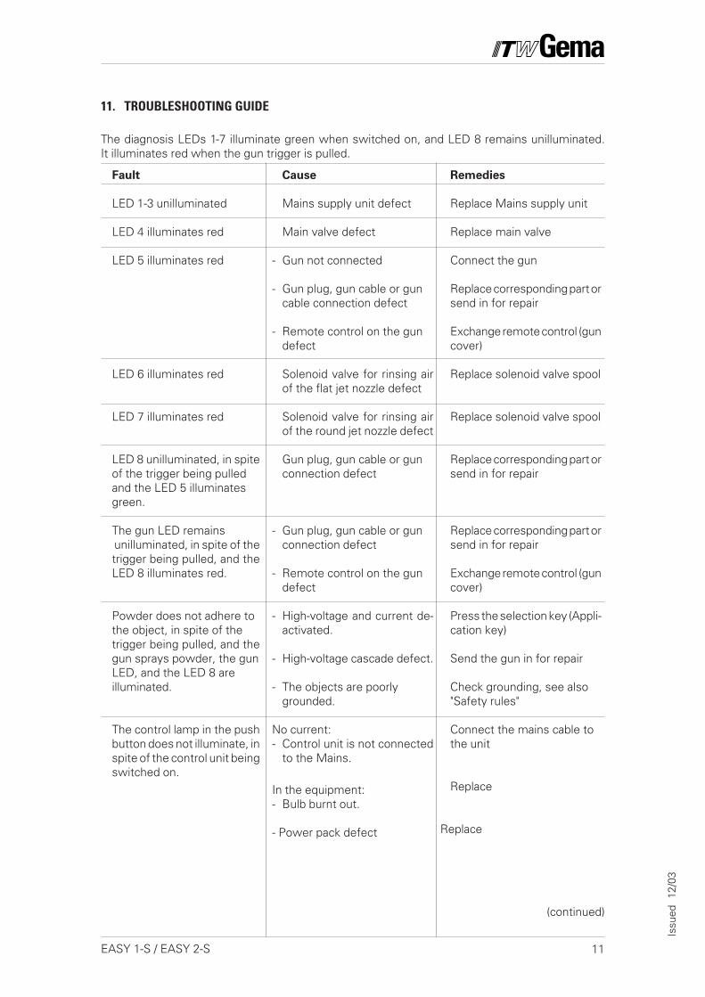
11. TROUBLESHOOTING GUIDE
(continued)
The diagnosis LEDs 1-7 illuminate green when switched on, and LED 8 remains unilluminated.It illuminates red when the gun trigger is pulled.
Fault
LED 1-3 unilluminated
LED 4 illuminates red
LED 5 illuminates red
LED 6 illuminates red
LED 7 illuminates red
LED 8 unilluminated, in spiteof the trigger being pulledand the LED 5 illuminatesgreen.
The gun LED remains unilluminated, in spite of thetrigger being pulled, and theLED 8 illuminates red.
Powder does not adhere tothe object, in spite of thetrigger being pulled, and thegun sprays powder, the gunLED, and the LED 8 areilluminated.
The control lamp in the pushbutton does not illuminate, inspite of the control unit beingswitched on.
Cause
Mains supply unit defect
Main valve defect
- Gun not connected
- Gun plug, gun cable or guncable connection defect
- Remote control on the gundefect
Solenoid valve for rinsing airof the flat jet nozzle defect
Solenoid valve for rinsing airof the round jet nozzle defect
Gun plug, gun cable or gunconnection defect
- Gun plug, gun cable or gunconnection defect
- Remote control on the gundefect
- High-voltage and current de-activated.
- High-voltage cascade defect.
- The objects are poorlygrounded.
No current:- Control unit is not connected
to the Mains.
In the equipment:- Bulb burnt out.
- Power pack defect
Remedies
Replace Mains supply unit
Replace main valve
Connect the gun
Replace corresponding part orsend in for repair
Exchange remote control (guncover)
Replace solenoid valve spool
Replace solenoid valve spool
Replace corresponding part orsend in for repair
Replace corresponding part orsend in for repair
Exchange remote control (guncover)
Press the selection key (Appli-cation key)
Send the gun in for repair
Check grounding, see also"Safety rules"
Connect the mains cable tothe unit
Replace
Replace
12 EASY 1-S / EASY 2-S
Issu
ed
12/0
3
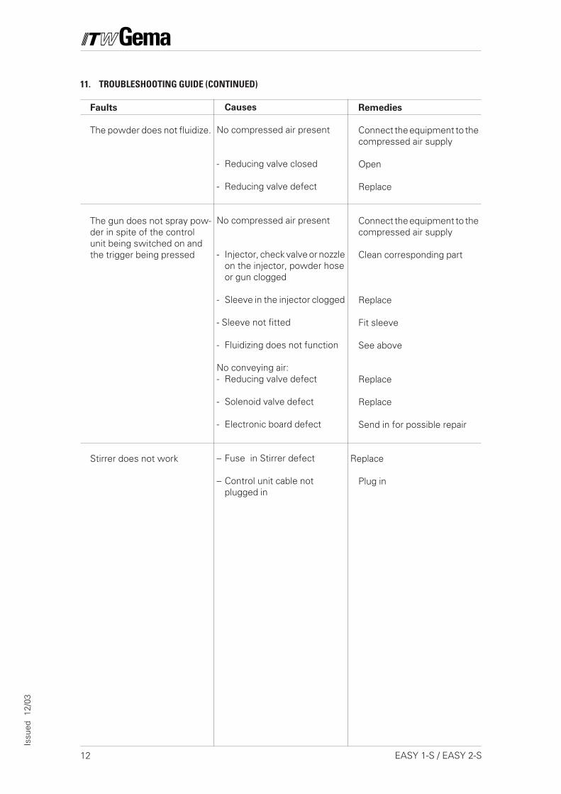
Faults
The powder does not fluidize.
The gun does not spray pow-der in spite of the controlunit being switched on andthe trigger being pressed
Stirrer does not work
Causes
No compressed air present
- Reducing valve closed
- Reducing valve defect
No compressed air present
- Injector, check valve or nozzleon the injector, powder hoseor gun clogged
- Sleeve in the injector clogged
- Sleeve not fitted
- Fluidizing does not function
No conveying air:- Reducing valve defect
- Solenoid valve defect
- Electronic board defect
– Fuse in Stirrer defect
– Control unit cable notplugged in
11. TROUBLESHOOTING GUIDE (CONTINUED)
Remedies
Connect the equipment to thecompressed air supply
Open
Replace
Connect the equipment to thecompressed air supply
Clean corresponding part
Replace
Fit sleeve
See above
Replace
Replace
Send in for possible repair
Replace
Plug in
13EASY 1-S / EASY 2-S
Issu
ed
12/0
3
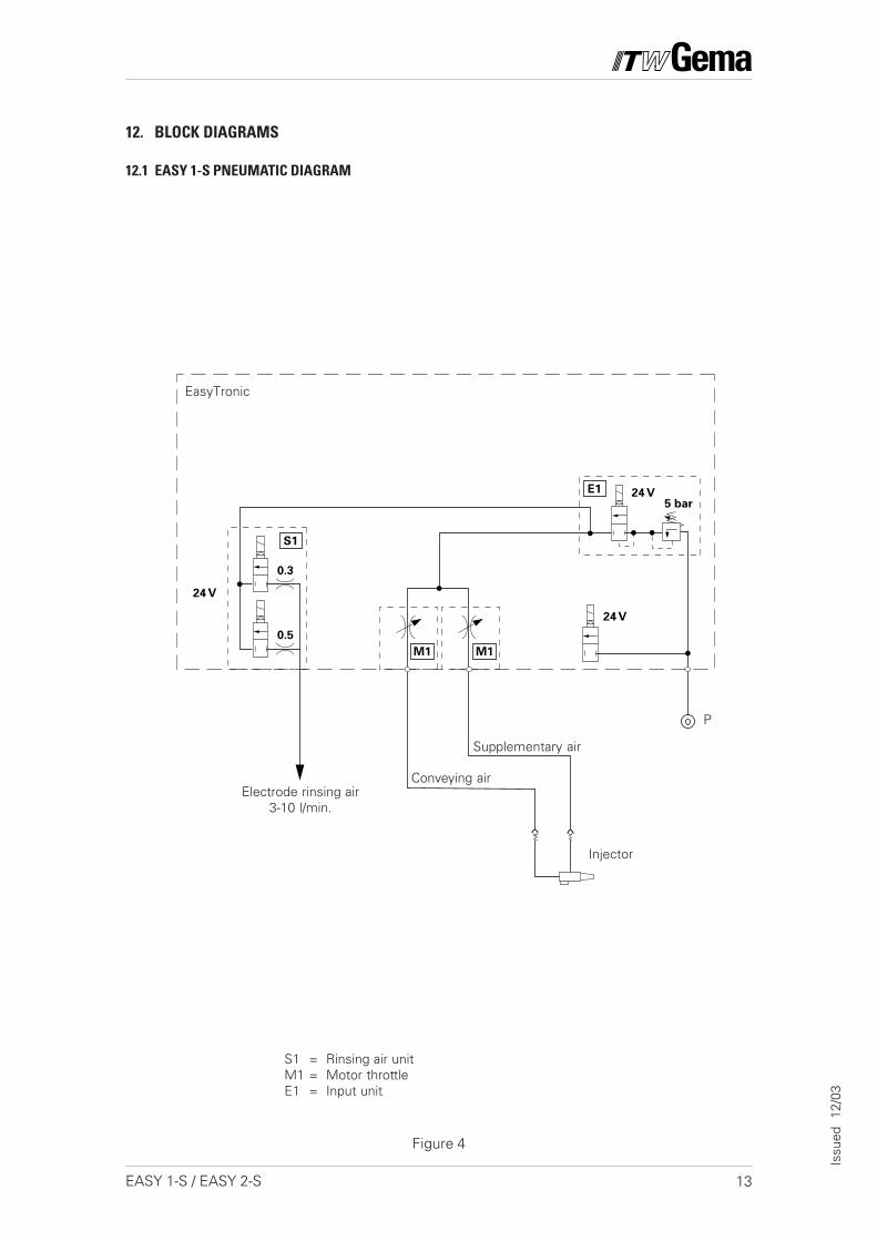
12. BLOCK DIAGRAMS
12.1 EASY 1-S PNEUMATIC DIAGRAM
P
Conveying air
Supplementary air
Electrode rinsing air3-10 l/min.
Injector
S1 = Rinsing air unitM1 = Motor throttleE1 = Input unit
Figure 4
EasyTronic
14 EASY 1-S / EASY 2-S
Issu
ed
12/0
3
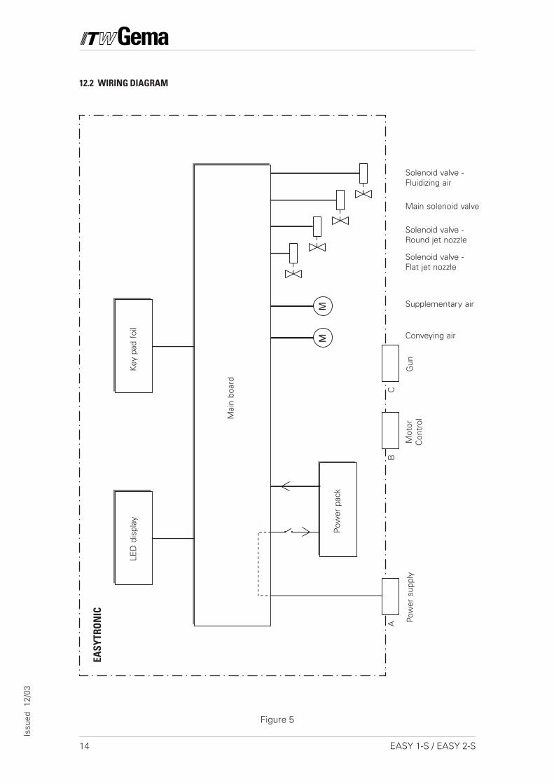
12.2 WIRING DIAGRAM
Figure 5
LED
dis
play
Key
pad
foi
l
Mai
n bo
ard
Pow
er s
uppl
yM
otor
Con
trol
Gun
Pow
er p
ack
Conveying air
Supplementary air
Solenoid valve -Round jet nozzle
Solenoid valve -Flat jet nozzle
Main solenoid valve
Solenoid valve -Fluidizing air
A
MM
BC
EASY
TRO
NIC
15EASY 1-S / EASY 2-S
Issu
ed
12/0
3
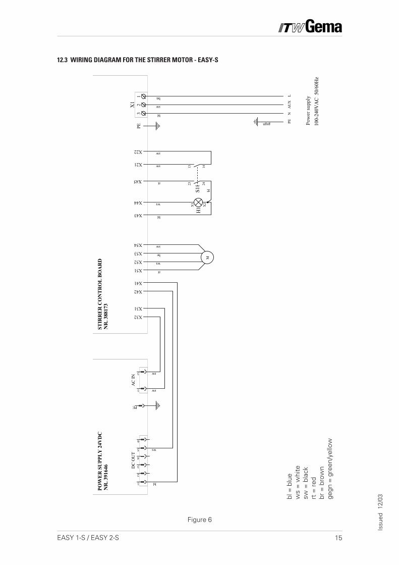
12.3 WIRING DIAGRAM FOR THE STIRRER MOTOR - EASY-S
Figure 6
PE
3
1
1
5
4
3
2
6
13 14
POW
ER S
UPP
LY 2
4VD
C
H1 X
2
X1
PEL
N
SPEI
SUN
G10
0-24
0VA
C 5
0/60
Hz
AC
IND
C O
UT
X32
X31
ws
gegn
bl
bl
bl
ws
NR
. 391
646
sw
sw
45V
A
STIR
RER
CO
NTR
OL
BOA
RD
NR
. 388
173
X42
X41
12
3PE
X1
AU
X
X21
X22
X44
X43
sw
bn
M
rt
ws
br
sw
X51
X52
X53
X54
sw
sw
23 24S1
X45 rt
bl
Pow
er s
uppl
y
bl =
blu
ew
s =
whi
tesw
= b
lack
rt =
red
br =
bro
wn
gegn
= g
reen
/yel
low

16 EASY 1-S / EASY 2-S
Issu
ed
12/0
3
NOTES:
17EASY 1-S / EASY 2-S
Issu
ed
12/0
3
13. SPARE PARTS LIST
13.1 ORDERING SPARE PARTS
When ordering Spare parts for powder coating equipment, pleaseindicate the following specifications:
1. Type and serial number of your powder coating equipment
2. Order number, quantity, and description of each spare part
Example:
1. Type EASY 1-S , Serial No.: XXX XXX
2. Order No.: 201 073, 5 pieces, Fine wire fuse
When ordering cable and hose material the length required must begiven.The spare part numbers of yard/meter ware always begins with 1.....and are always marked with an * in the spare parts list.
Wear parts are always marked with a #.
All dimensions for plastic powder hoses are given as external diameter(o/d) and internal diameter (i/d):
e. g. ø 8 / 6 mm, 8 mm outside diameter / 6 mm inside diameter(i/d).
18 EASY 1-S / EASY 2-S
Issu
ed
12/0
3
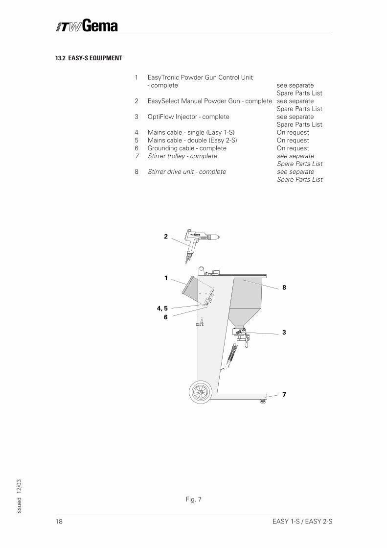
13.2 EASY-S EQUIPMENT
1 EasyTronic Powder Gun Control Unit- complete see separate
Spare Parts List2 EasySelect Manual Powder Gun - complete see separate
Spare Parts List3 OptiFlow Injector - complete see separate
Spare Parts List4 Mains cable - single (Easy 1-S) On request5 Mains cable - double (Easy 2-S) On request6 Grounding cable - complete On request7 Stirrer trolley - complete see separate
Spare Parts List8 Stirrer drive unit - complete see separate
Spare Parts List
3
8
4, 5
7
2
1
6
Fig. 7
19EASY 1-S / EASY 2-S
Issu
ed
12/0
3
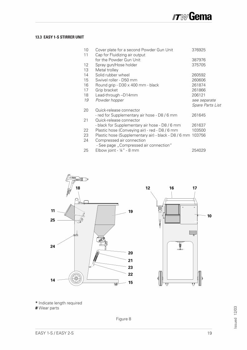
* Indicate length required# Wear parts
13.3 EASY 1-S STIRRER UNIT
Figure 8
10 Cover plate for a second Powder Gun Unit 37692511 Cap for Fluidizing air output
for the Powder Gun Unit 38797612 Spray gun/Hose holder 37570513 Metal trolley14 Solid rubber wheel 26059215 Swivel roller - D50 mm 26060616 Round grip - D30 x 400 mm - black 26187417 Grip bracket 26186618 Lead-through –D14mm 20612119 Powder hopper see separate
Spare Parts List20 Quick-release connector
- red for Supplementary air hose - D8 / 6 mm 26164521 Quick-release connector
- black for Supplementary air hose - D8 / 6 mm 26163722 Plastic hose (Conveying air) - red - D8 / 6 mm 10350023 Plastic hose (Supplementary air) - black - D8 / 6 mm 10375624 Compressed air connection
- See page „Compressed air connection“25 Elbow joint - ¼“ - 8 mm 254029
16
10
12 17
19
21
1415
24
11
25
23
22
20
18

20 EASY 1-S / EASY 2-S
Issu
ed
11/0
4
* Indicate length required
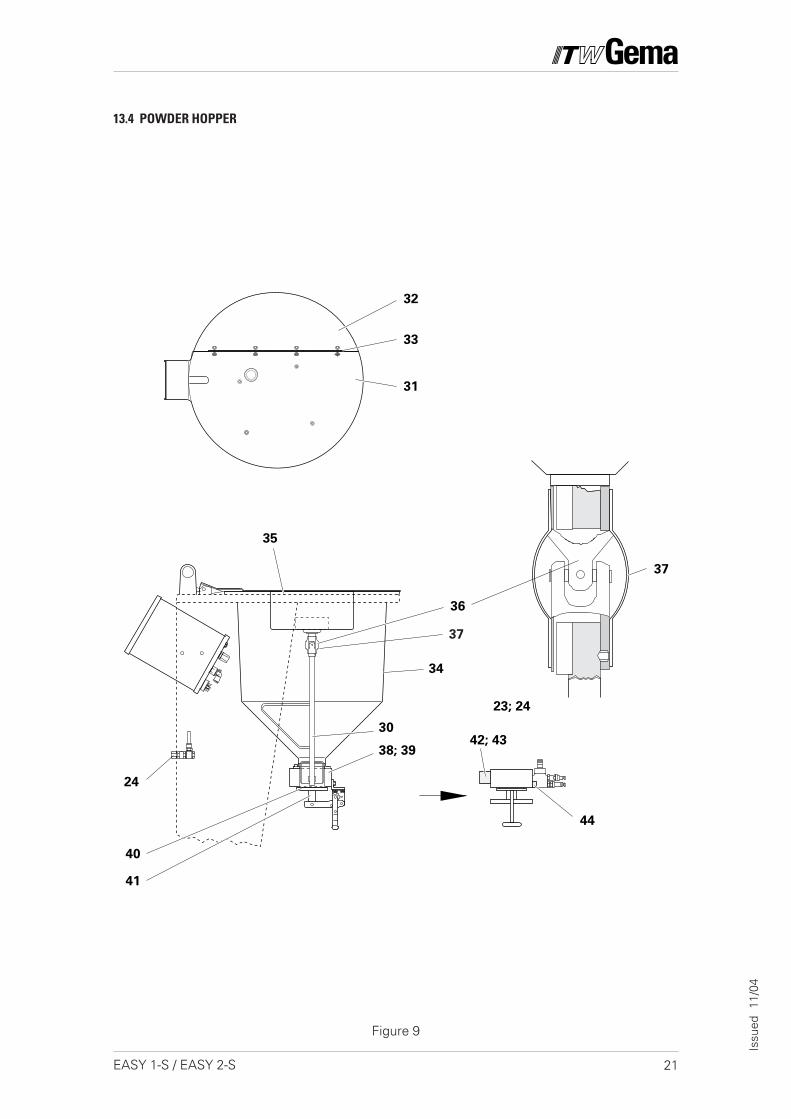
13.4 POWDER HOPPER
30 Mini-brush (not shown) 366 86231 Main filler cover 393 91632 Filler cover 380 63633 Hinge 305 47234 Powder hopper 366 85435 Seal for Powder hopper 101 63036 Cardan joint D=12 mm 206 369
206 075214 728
37 Sleeve for Cardan joint 206 35038 Distributor head 379 39539 O Ring – D = 67*2 mm 236 40340 Gasket for emptying valve 303 24041 Emptying valve with clamping lever 303 19442 Grommet 380 29643 O Ring for the Grommet 231 517
Key 4x4x16 mm (to Item 36)Grubscrew M4x5 mm (to Item 36)
44 Injector holder 380 288
21EASY 1-S / EASY 2-S
Issu
ed
11/0
4
Figure 9
30
36
38; 39
40
41
35
42; 43
24
34
31
32
33
44
37
23; 24
37
13.4 POWDER HOPPER
22 EASY 1-S / EASY 2-S
Issu
ed
11/0
4
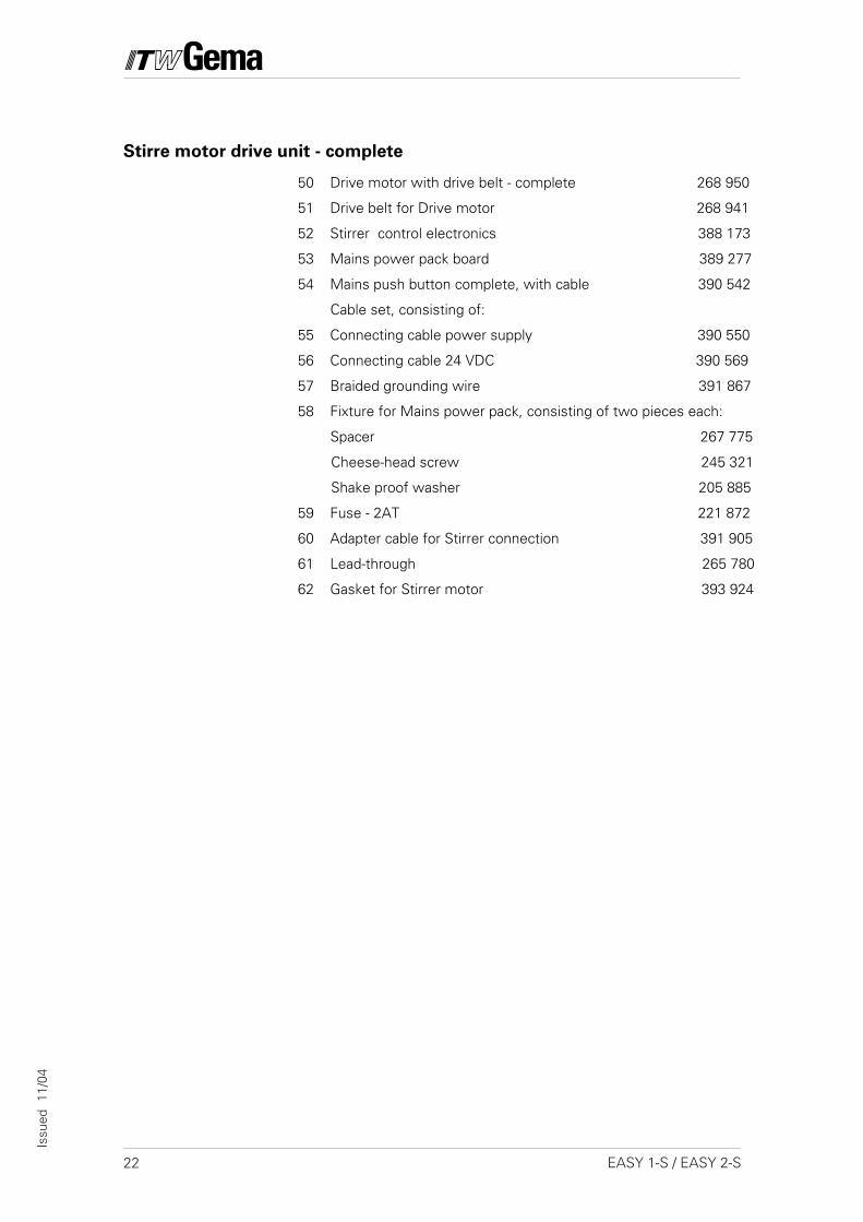
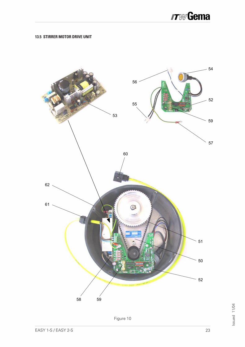
Stirre motor drive unit - complete
50 Drive motor with drive belt - complete 268 950
51 Drive belt for Drive motor 268 941
52 Stirrer control electronics 388 173
53 Mains power pack board 389 277
54 Mains push button complete, with cable 390 542
Cable set, consisting of:
55 Connecting cable power supply 390 550
56 Connecting cable 24 VDC 390 569
57 Braided grounding wire 391 867
58 Fixture for Mains power pack, consisting of two pieces each:
Spacer 267 775
Cheese-head screw 245 321
Shake proof washer 205 885
59 Fuse - 2AT 221 872
60 Adapter cable for Stirrer connection 391 905
61 Lead-through 265 780
62 Gasket for Stirrer motor 393 924
23EASY 1-S / EASY 2-S
Issu
ed
11/0
4
13.5 STIRRER MOTOR DRIVE UNIT
Figure 10
53
60
61
58
62
54
52
51
50
59
57
55
56
52
59
24 EASY 1-S / EASY 2-S
Issu
ed
12/0
3
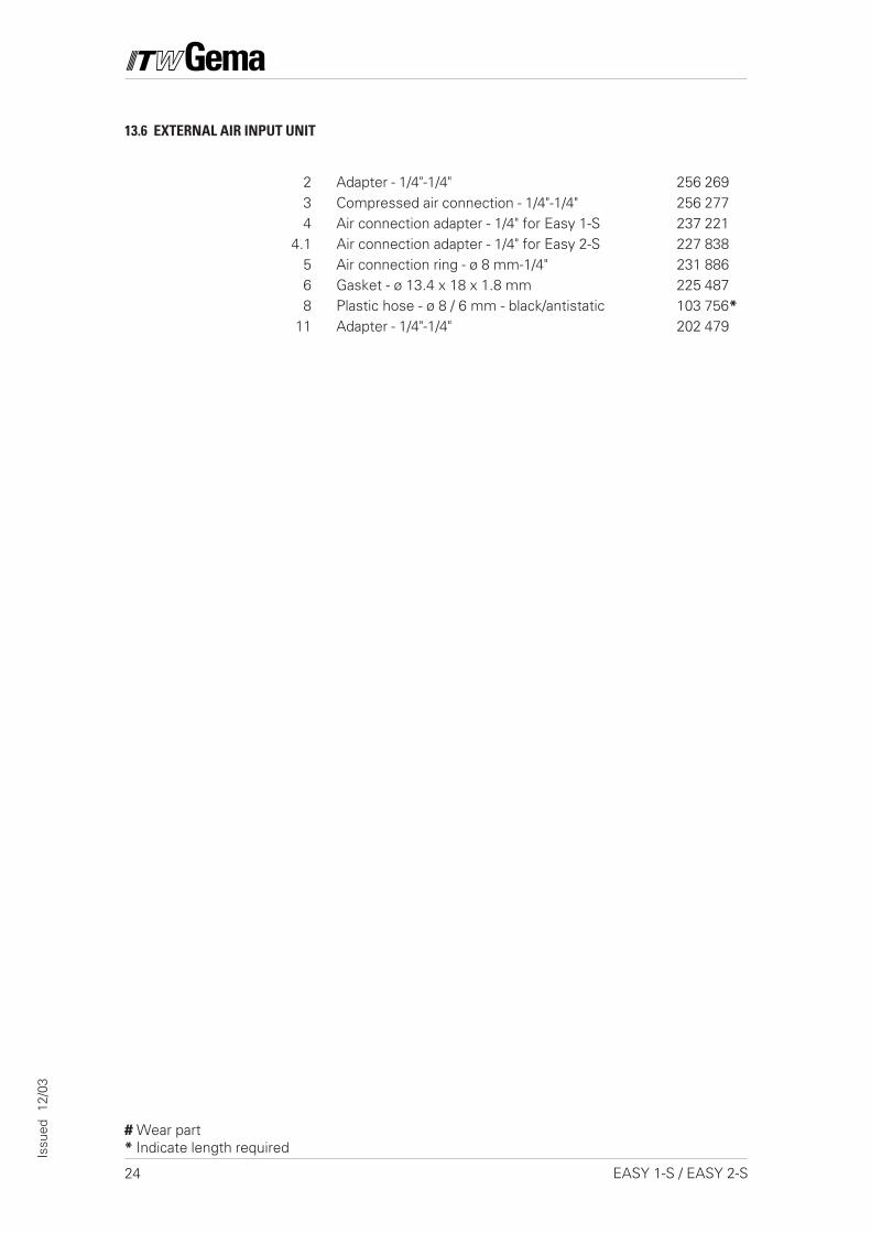
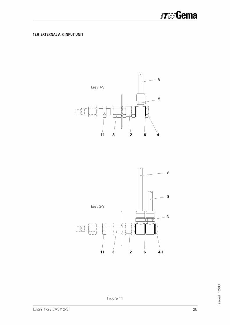
13.6 EXTERNAL AIR INPUT UNIT
2 Adapter - 1/4"-1/4" 256 2693 Compressed air connection - 1/4"-1/4" 256 2774 Air connection adapter - 1/4" for Easy 1-S 237 221
4.1 Air connection adapter - 1/4" for Easy 2-S 227 8385 Air connection ring - ø 8 mm-1/4" 231 8866 Gasket - ø 13.4 x 18 x 1.8 mm 225 4878 Plastic hose - ø 8 / 6 mm - black/antistatic 103 756*
11 Adapter - 1/4"-1/4" 202 479
# Wear part* Indicate length required
25EASY 1-S / EASY 2-S
Issu
ed
12/0
3
11 3 2 6 4.1
11 3 2 6 4
5
8
5
8
8
Easy 1-S
Easy 2-S
13.6 EXTERNAL AIR INPUT UNIT
Figure 11
26 EASY 1-S / EASY 2-S
Issu
ed
12/0
3
© Copyright 2000 ITW Gema AG.All rights reserved.
This publication is protected by copyright. Unauthorized copying isprohibited by law. No part of this publication may be reproduced,photocopied, translated, stored on a retrieval system or transmitted inany form or by any means for any purpose, neither as a whole norpartially, without the express written consent of ITW Gema AG.
OptiTronic, OptiGun, EasyTronic, EasySelect, EasyFlow andSuperCorona are registered trademarks of ITW Gema AG.
OptiMatic, OptiMove, OptiMaster, OptiPlus, OptiMulti and Gematicare trademarks of ITW Gema AG.
All other product names are trademarks or registered trademarks oftheir respective holders.
Reference is made in this manual to different trademarks or registeredtrademarks. Such references do not mean that the manufacturersconcerned approve of or are bound in any form by this manual. Wehave endeavoured to retain the preferred spelling of the trademarks,and registered trademarks of the copyright holders.
To the best of our knowledge and belief, the information contained inthis publication was correct and valid on the date of issue. ITW GemaAG makes no representations or warranties with respect to thecontents or use of this publication, and reserves the right to revise thispublication and make changes to its content without prior notice.
Printed in Switzerland
ITW Gema AG
Mövenstrass 179051 St.GallSwitzerland
Tel.: +41 71 313 83 00Fax.: +41 71 313 83 83
E-Mail: [email protected]: www.itwgema.ch


