11
Eaton ELocker™ Differential Operating & Installation Instructions 99998142000 Eaton Performance Differentials ELocker™ – Pin type ELocker™ – Collar type

Eaton ELocker™ Differential Operating & Installation Instructions
99998142000
Eaton Performance Differentials
ELocker™ – Pin type
ELocker™ – Collar type

Eaton ELocker™ Differential Operating & Installation Instructions
99998142000
Congratulations! You have just purchased the latest innovation in locking differential technology – the Eaton ELocker™ differential.
The following information has been designed to help you become familiar with how your Eaton ELocker™ differential works, how it should be installed, and how it should be used.
How does the Eaton ELocker™ differential work?
The Eaton ELocker™ differential is a driver-controlled, electronically activated locking differential that can easily replace a traditional differential to gain much more traction and off-road capability. During everyday use or on-road driving, the Eaton ELocker™ differential operates as an “open” differential. This enables easy maneuverability in tight parking lots and good
road manners while cornering. However, when the terrain gets tough, or ultimate traction is needed, a switch allows the driver to fully lock the differential. A locked differential provides 100% of the drive torque to both wheels at any given moment, enabling difficult obstacles to be easily overcome. Eaton ELocker™ differentials can be used on the front, as well as the rear axle for off-road capabilities, or track use that is unsurpassed by other traction modifying devices.
The Eaton ELocker™ differential is a new age electro-mechanical product from Eaton Corporation. When the switch is activated, electric current is supplied to a powerful electromagnet. As the electromagnet is energized, a torque is created
on a drag-plate that activates a ramping mechanism. The ramping mechanism, in turn, translates rotational force into the axial motion of a locking mechanism. The locking mechanism engages into slots or tabs on the differential side gear and locks the side gear rotation to the differential housing. The result is on-demand traction and a fully locked differential. Once the obstacle is overcome and the Eaton ELocker™ differential is deactivated through the switch, a series of return springs promptly force the locking mechanism to disengage and the Eaton ELocker™ differential again operates as an “open” differential.
How do I use the Eaton ELocker™ differential?
The following information discusses proper operation of the Eaton ELocker™ differential:
Differential engagement should occur before an obstacle is encountered. If you feel that you are in a situation that may require extra traction, it is recommended to use the Eaton ELocker™ differential as an anticipatory device.
WARNING! - Only engage the Eaton ELocker™ differential while the vehicle is stationary or operating at speeds of 3 mph or less with minimal wheel slippage. Engaging the Eaton ELocker™ while the wheel is spinning at a high rate or the vehicle is moving at more that 3 mph may damage the differential’s engagement pins or lock collar will be considered improper or abnormal use voiding the warranty. Eaton will reject warranty claims if the returned Eaton ELocker™ has engagement pins or lock collars damaged by operation contrary to this warning.
Differential engagement should be deactivated after the difficult terrain is overcome. It is not recommended to deactivate the Eaton ELocker™ differential while the drivetrain has load or bind on it, such as under cornering. When the drivetrain is loaded, the Eaton ELocker™ differential may not immediately disengage, resulting in a locked differential when it is not desired.
Differential engagement should not be maintained at high speeds (greater than 20 mph). A locked differential at higher speeds can cause undesirable vehicle behavior or loss of vehicle control. The Eaton ELocker™ differential may be
deactivated via the switch while the vehicle is in motion.
When a front or rear differential is locked, the behavior and maneuverability of a vehicle is altered. Steering response and vehicle maneuverability may be reduced dramatically. Steering may be difficult with a front Eaton ELocker™ differential engaged. For this reason, a front Eaton ELocker™ differential should be used only at low vehicle speeds and only in 4WD mode.
Differential engagement should be used on low traction surfaces, such as those encountered in off-road use. Continuous operation of a locked differential on high traction surfaces produces unnecessary strain on drivetrain and chassis components while cornering in the vehicle. Caution should be taken when operating locked differentials on slippery terrain,

Eaton ELocker™ Differential Operating & Installation Instructions
99998142000
such as icy surfaces. High speeds on slippery surfaces with a differential locked can result in undesirable vehicle behavior or loss of vehicle control. Always operate vehicle with care and reduced speed.
How do I maintain my ELocker™ differential?
The Eaton ELocker™ differential is built for robust performance and life. It is constructed of precision-forged gears,
hardened lock pins or lock collar, and a durable cast nodular iron housing.
Installing a new differential is a fairly demanding job that requires close attention to tolerances and pre-loads. Each vehicle is different, so it is necessary to follow all of the vehicle manufacturer's recommendations and installation requirements.
The following information details a few tech tips to ensure long life for your Eaton ELocker™ differential with proper installation and maintenance:
1. Side-bearing pre-load is extremely critical and must be set to the specifications of the vehicle’s original equipment manufacturer.
2. Ring gear backlash is also performance critical and must be set to the specifications of the vehicle’s original equipment manufacturer. Failure to properly set gear backlash can result in a poor ring and pinion contact pattern, and undesirable noise is likely.
3. If installing a new ring and pinion with your Eaton ELocker™ differential, proper break-in will help extend performance
life. Avoid wide-open throttle starts for the first 50 miles. Avoid trailer towing for the first 500 miles. Once a gear set pattern has been established (typically within 100 miles) corrections will not be effective.
4. The axle lubricant recommended by the vehicle manufacturer should be used and should be changed periodically per the vehicle manufacturer’s recommendations. Always drain and dispose of used lubricant appropriately.
5. Dirt and water deteriorate any differential. Always replace the cover gasket and seal it properly. A silicone sealant is recommended when using a non-synthetic gear lubricant; where a non-RTV sealant should be used with synthetic lubricants. Torque the cover plate and carrier bolts according to the vehicle’s original equipment manufacturer's specifications.
Installation Instructions The following steps outline the procedure for installing an
Eaton ELocker™ differential. It is recommended that you read the entire installation instructions prior to beginning the installation. Please consult the vehicle service manual, in
conjunction with these instructions, to properly assemble and disassemble all components.
Tools and Equipment Vehicle lift or hydraulic jack Grease pencil Jack-stands Drill & Bits
Pneumatic impact wrench and sockets Standard/Metric socket and wrench set Shop light
Oil drain pan Funnel Gasket scraper
Magnetic base dial indicator Large pry-bar Drift punch and hammer
Bearing driver Heavy leather or rubber hammer Torque wrench
ELocker™ Operating & Installation Instructions
99998142000
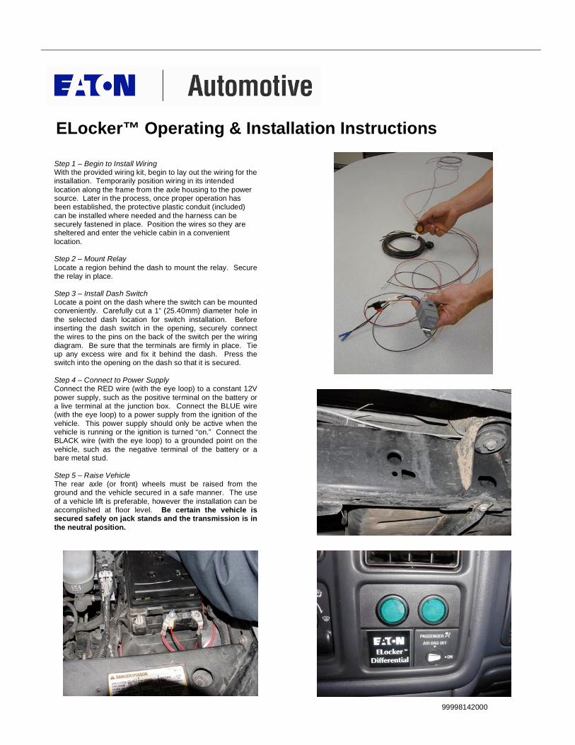
Step 1 – Begin to Install Wiring With the provided wiring kit, begin to lay out the wiring for the installation. Temporarily position wiring in its intended
location along the frame from the axle housing to the power source. Later in the process, once proper operation has been established, the protective plastic conduit (included)
can be installed where needed and the harness can be securely fastened in place. Position the wires so they are sheltered and enter the vehicle cabin in a convenient
location. Step 2 – Mount Relay
Locate a region behind the dash to mount the relay. Secure the relay in place.
Step 3 – Install Dash Switch Locate a point on the dash where the switch can be mounted conveniently. Carefully cut a 1” (25.40mm) diameter hole in
the selected dash location for switch installation. Before inserting the dash switch in the opening, securely connect the wires to the pins on the back of the switch per the wiring
diagram. Be sure that the terminals are firmly in place. Tie up any excess wire and fix it behind the dash. Press the switch into the opening on the dash so that it is secured.
Step 4 – Connect to Power Supply Connect the RED wire (with the eye loop) to a constant 12V
power supply, such as the positive terminal on the battery or a live terminal at the junction box. Connect the BLUE wire (with the eye loop) to a power supply from the ignition of the
vehicle. This power supply should only be active when the vehicle is running or the ignition is turned “on.” Connect the BLACK wire (with the eye loop) to a grounded point on the
vehicle, such as the negative terminal of the battery or a bare metal stud.
Step 5 – Raise Vehicle The rear axle (or front) wheels must be raised from the ground and the vehicle secured in a safe manner. The use
of a vehicle lift is preferable, however the installation can be accomplished at floor level. Be certain the vehicle is secured safely on jack stands and the transmission is in
the neutral position.

ELocker™ Operating & Installation Instructions
99998142000
Step 6 – Remove Wheels Remove the rear wheels and set them aside.
Step 7 – Disassemble Brakes Remove the brake drums. (If the vehicle is equipped with rear disc brakes, carefully remove the calipers and secure
them so that they do not hang by the brake lines. Then remove the brake rotor.) Note: A rear axle assembly is depicted in these photos. Additional steps may be
necessary as required for a front axle application. Step 8 - Drain Gear Lube
Position a drain pan under the axle assembly. Remove the differential cover, starting with the cover bolts at the bottom. It is helpful to loosen, but leave threaded, a bolt at the top to
hold the differential cover. Then, gently pry the cover off, starting at the bottom. Permit the gear oil to fully drain, and then remove the cover entirely. Dispose of waste oil
properly.
Step 9 – Measure Backlash If the same ring and pinion gear set will be used, it is
necessary to measure the current gear backlash (movement between the drive pinion and differential ring gear, typically 0.010 ± 0.002”). Wipe away excess gear oil from work
surfaces. Secure a magnetic base dial indicator on the flat surface of the axle housing. Measure backlash by measuring the free movement of the ring gear back and forth
between the stationary drive pinion gear teeth. Record your measurement. (If you are replacing the ring and pinion gear set at this time, refer to the vehicle service manual for
applicable procedures.
Step 10 – Remove Differential Pinion Shaft – (Required only
on C-clip equipped axles) Remove the pinion shaft lock screw then slide the pinion shaft completely out of the differential housing.

ELocker™ Operating & Installation Instructions
99998142000
Step 11 – Remove C-Clips (if so equipped) Push each axle inward, one at a time, exposing the axle
retaining C-clip at the axle end inside the differential housing. Remove the C-clips for both axles. A magnetic wand is useful in extracting the C-clips.
Step 12 – Move Axle Shafts Carefully pull the axle shafts outward enough to clear the
differential bearing hub. Take care to not damage the axle shaft bearings and seals when moving the axles. Temporarily reinstall the pinion shaft and thread the pinion
shaft lock screw.
Step 13 – Remove Bearing Caps With a grease pencil, mark the bearing caps “Right” and “Left,” “Top” and “Bottom.” They will need to be reinstalled in
their original positions. Remove the bearing caps.
Step 14 – Remove Differential With a pry bar, carefully pry the differential assembly outward while preventing it from falling out by supporting it
with your hand. Do not pry differential out by contact with pry bar and ring gear. Damage could result to ring gear teeth. Once the differential is free, remove it along
with the left and right bearing cups and shims. Keep track of their original locations.
Step 15– Remove Ring Gear
Some ring gear bolts have left hand threads, and must be removed accordingly. Remove the ring gear bolts by loosening bolts opposite one another, then at midpoints
between the loose bolts. The ring gear will be pressed on the pilot diameter of the differential and must be pressed off or removed using a hammer and drift punch. Note the
orientation of the speed pick-up ring found on some differentials. Do not strike the speed pick-up ring, as it is easily damaged or broken.
ELocker™ Operating & Installation Instructions
99998142000
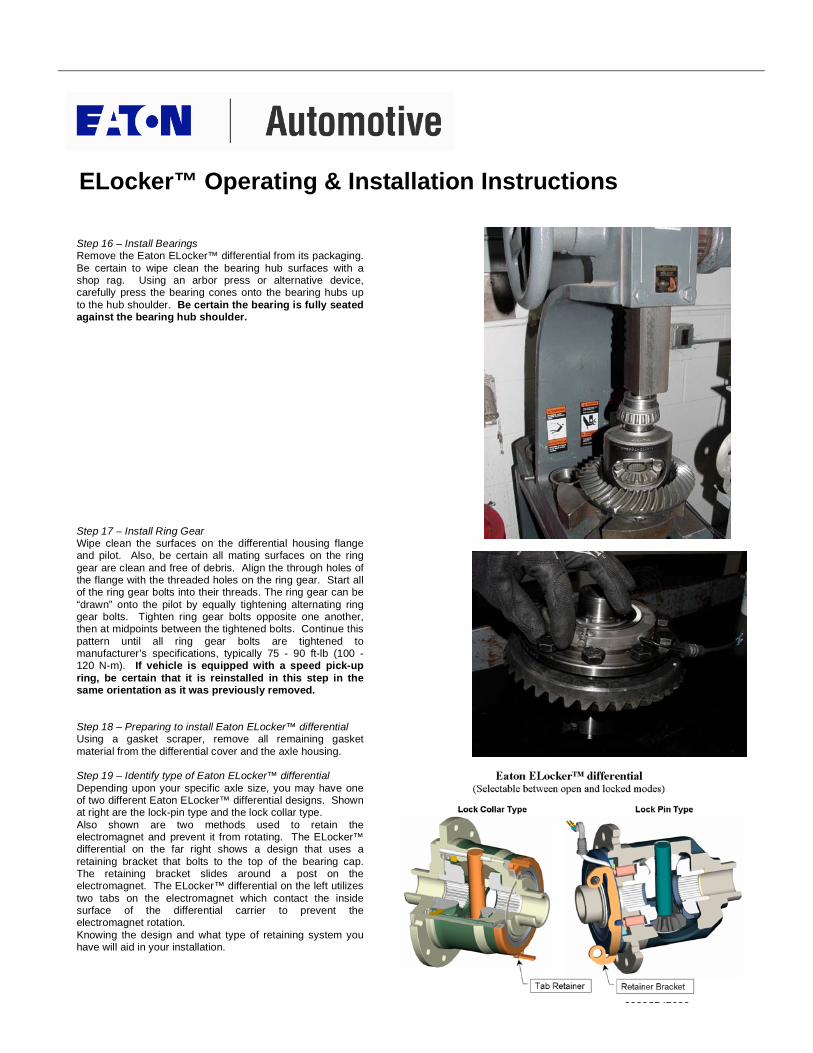
Step 16 – Install Bearings Remove the Eaton ELocker™ differential from its packaging.
Be certain to wipe clean the bearing hub surfaces with a shop rag. Using an arbor press or alternative device, carefully press the bearing cones onto the bearing hubs up
to the hub shoulder. Be certain the bearing is fully seated against the bearing hub shoulder.
Step 17 – Install Ring Gear Wipe clean the surfaces on the differential housing flange and pilot. Also, be certain all mating surfaces on the ring
gear are clean and free of debris. Align the through holes of the flange with the threaded holes on the ring gear. Start all of the ring gear bolts into their threads. The ring gear can be
“drawn” onto the pilot by equally tightening alternating ring gear bolts. Tighten ring gear bolts opposite one another, then at midpoints between the tightened bolts. Continue this
pattern until all ring gear bolts are tightened to manufacturer’s specifications, typically 75 - 90 ft-lb (100 - 120 N-m). If vehicle is equipped with a speed pick-up
ring, be certain that it is reinstalled in this step in the same orientation as it was previously removed.
Step 18 – Preparing to install Eaton ELocker™ differential Using a gasket scraper, remove all remaining gasket
material from the differential cover and the axle housing. Step 19 – Identify type of Eaton ELocker™ differential
Depending upon your specific axle size, you may have one of two different Eaton ELocker™ differential designs. Shown at right are the lock-pin type and the lock collar type.
Also shown are two methods used to retain the electromagnet and prevent it from rotating. The ELocker™ differential on the far right shows a design that uses a
retaining bracket that bolts to the top of the bearing cap. The retaining bracket slides around a post on the electromagnet. The ELocker™ differential on the left utilizes
two tabs on the electromagnet which contact the inside surface of the differential carrier to prevent the electromagnet rotation.
Knowing the design and what type of retaining system you have will aid in your installation.

ELocker™ Operating & Installation Instructions
99998142000
Step 20 – Drill Grommet Hole An exit hole for the Eaton ELocker™ coil wire grommet will
need to be drilled in the upper left or right quadrant of the axle housing depending upon design. Fit the ELocker into the axle housing taking careful note of wire location. The
hole location should be in an area that will keep the wiring away from rotating parts and sharp edges. Once the ideal grommet location has been determined, based on wire
length and axle housing configuration, remove unit and prepare for drilling. You will need to mark, punch, and drill a
” (12.7mm) maximum diameter thru hole. Note: When
drilling through a material thickness less than ” (6.35mm) a slightly smaller hole of 29/64” (11.51mm) –minimum diameter will insure a tighter seal. Take care when drilling
not to contaminate the differential sump with metal shavings. Cover bearings and bearing surfaces before drilling and clean area after drilling. A shop vacuum cleaner works well.
Step 21 – Seat Eaton ELocker™ Differential in Axle Add side bearing cups and side bearing shims (left and right), reassembling in the same configuration as previous
shims were removed. Refer to vehicle service manual for applicable procedures regarding side bearing preload. Firmly grasping the entire assembly, including bearing cups
and shims, place assembly as far as possible into the axle housing. As you install, orient the electromagnet so the wire leads exit the newly drilled hole. Use caution to not pinch
or damage electrical wires while seating the Eaton ELocker™ differential. Take care to ensure the bearing cups and shims are aligned well. Using a heavy leather or
rubber mallet, fully seat the differential assembly in the axle housing. Do not strike the electromagnet or speed pick-up ring (if equipped), as damage may occur. A drift
punch or shim driver tool may be useful in seating shims. Note: Anti-rotation tabs may need to be ground or filed to ensure free play in the electromagnet when the differential is
seated in the axle housing.

ELocker™ Operating & Installation Instructions
99998142000
Step 22 – Install Anti-rotation Bracket (If equipped) Locate the anti-rotation tab on the electromagnet. With the bearing cap seated on the electromagnet side, place the
anti-rotation bracket over the anti-rotation tab. Install and finger-tighten the bearing cap bolts over the anti-rotation bracket, ensuring it is well aligned. Note: The anti rotation
bracket configuration may vary depending on application. The bracket may need to be adjusted by bending to ensure electromagnet free play.
Step 23 – Complete Bearing Cap Installation Complete the installation of left and right bearing caps in the
same orientation as they were removed. “Snug” each bearing cap in place, then tighten bearing cap bolts to the proper torque specification.
Step 24 – Measure Backlash Use the previous procedure to re-check the drive pinion to
ring gear backlash. If the backlash is not the same, re-shimming will be necessary. Please refer to the vehicle’s service manual for applicable procedures for adjusting
backlash. If a new ring and pinion gear set is to be installed, adjust backlash to be within the service manual specification. Once it has been determined that the
differential will now stay in the axle housing, fully seat the grommet through the newly drilled hole.
Step 25 – Reinstall Axle Shafts If C-clip equipped, temporarily remove the differential pinion
shaft. Carefully push both axle shafts inward so that their C-clip grooves may be accessed at the center of the differential. Again, it is important to take care not to damage
bearing and shaft seals when moving the axles. Install each C-clip onto the groove in the axle and gently pull the axle out, ensuring that the C-clip fully seats in the counter-bore
on the differential side gear. Reinstall differential pinion shaft and pinion shaft lock screw, tightening the lock screw to the proper torque specification.
Step 26 – Test Electronics
Temporarily connect the Eaton ELocker™ differential to the lead lines from the relay as installed previously. Note: A special weather-tight connection for the coil wires is provided
along with the wiring harness. This is to be installed once the coil wires and grommet are in place. Test the electronics by turning on the ignition in the vehicle. Activate the dash
switch to the “ON” position. Examine the armature plate directly next to the electromagnet and confirm that it is firmly drawn into the electromagnet. Rotate the drive shaft a
minimum of one full revolution while attempting to hold one wheel stationary. While the drive shaft is being turned, you should feel the wheel that is being held stationary “lock” as
both wheels begin to rotate together. If lock-up is not evident, check to confirm proper electrical connections.

ELocker™ Operating & Installation Instructions
99998142000
Step 27 – Reinstall Differential Cover Wipe both surfaces clean before lining up the new gasket to
the axle assembly. Line up the bolt pattern of the cover plate to that of the gasket and axle assembly. Use sealant if recommended. Tighten differential cover bolts finger-tight
then tighten differential cover in an alternating manner up to the proper torque specification.
Step 28 – Complete Wiring Install plastic conduit over any exposed wiring harness
sections requiring protection. Confirm that all wiring and connectors are securely fastened and cannot be caught in moving parts or road terrain. Make sure that the wiring
harness is securely fastened with wire ties as necessary. Be certain to leave excess wire to provide slack for suspension travel.
Step 29 – Fill Axle with Lubricant Remove lubricant fill plug and install the recommended volume and type of rear axle lubricant. Reinstall and tighten
fill plug. Step 30 – Reassemble Brake Components
Inspect and reassemble all brake components. Refer to vehicle service manual for applicable procedures regarding the reassembly or replacement of brake
components. Step 31 – Reinstall Wheels
Reinstall the wheels taking care to tighten lug nuts in an alternating manner to the proper torque specification.
Step 32 – Lower Vehicle Take account of all tools and components. Lower the vehicle to the ground.
Step 33 – Test Eaton ELocker™ Differential Activate the Eaton ELocker™ differential by pressing the
dash mounted push button switch. Observe that the indicator lamp is lit when the Eaton ELocker™ differential is activated. Turn the steering wheel all the
way to the left and drive in tight circles on loose soil. Observe the bind-up or wheel scrub while circling when the Eaton ELocker™ differential is activated. This
confirms proper functionality. Your newly installed Eaton ELocker™ differential is ready to be used responsibly.

ELocker™ Operating & Installation Instructions
99998142000


