31
Eaton ® ET5040 Crimp Machine Operator's Manual

Eaton® ET5040 Crimp Machine Operator's Manual

2 EATON ET5040 Operator´s Manual E-EQCR-TT002-E May 2014
Table of Contents
ET5040 Operator's Manual
Safety Instructions . . . . . . . . . . . . . . . . . . . . . . . . . . . . . . . . . . . . . . . . . . . . . . . . . . . . . . . . . . . . . . . . . . . . . . . . . . . . . . . . . . . . . . . . .3
Specifications . . . . . . . . . . . . . . . . . . . . . . . . . . . . . . . . . . . . . . . . . . . . . . . . . . . . . . . . . . . . . . . . . . . . . . . . . . . . . . . . . . . . . . . . . . . .4
Machine Setup and Installation
Environment . . . . . . . . . . . . . . . . . . . . . . . . . . . . . . . . . . . . . . . . . . . . . . . . . . . . . . . . . . . . . . . . . . . . . . . . . . . . . . . . . . . . . . . . . .4
Height Adjustment . . . . . . . . . . . . . . . . . . . . . . . . . . . . . . . . . . . . . . . . . . . . . . . . . . . . . . . . . . . . . . . . . . . . . . . . . . . . . . . . . . . . .4
Filling Hydraulic Fluid Reservoir . . . . . . . . . . . . . . . . . . . . . . . . . . . . . . . . . . . . . . . . . . . . . . . . . . . . . . . . . . . . . . . . . . . . . . . . . . .5
Connecting the Electric Supply . . . . . . . . . . . . . . . . . . . . . . . . . . . . . . . . . . . . . . . . . . . . . . . . . . . . . . . . . . . . . . . . . . . . . . . . . . .5
Ventilating the Hydraulic System . . . . . . . . . . . . . . . . . . . . . . . . . . . . . . . . . . . . . . . . . . . . . . . . . . . . . . . . . . . . . . . . . . . . . . . . . .5
Control Symbols Overview . . . . . . . . . . . . . . . . . . . . . . . . . . . . . . . . . . . . . . . . . . . . . . . . . . . . . . . . . . . . . . . . . . . . . . . . . . . . . . . . 6 - 7
Tooling - Installation (QDC) . . . . . . . . . . . . . . . . . . . . . . . . . . . . . . . . . . . . . . . . . . . . . . . . . . . . . . . . . . . . . . . . . . . . . . . . . . . . . . . . . . .8
Tooling - Removal (QDC) . . . . . . . . . . . . . . . . . . . . . . . . . . . . . . . . . . . . . . . . . . . . . . . . . . . . . . . . . . . . . . . . . . . . . . . . . . . . . . . . . . . . .9
Tooling - Installation/Removal (Die-Key)
Tooling Installation with Die Key . . . . . . . . . . . . . . . . . . . . . . . . . . . . . . . . . . . . . . . . . . . . . . . . . . . . . . . . . . . . . . . . . . . . . . . . .10
Tooling Removal with Die Key . . . . . . . . . . . . . . . . . . . . . . . . . . . . . . . . . . . . . . . . . . . . . . . . . . . . . . . . . . . . . . . . . . . . . . . . . .10
General Notes for Crimping . . . . . . . . . . . . . . . . . . . . . . . . . . . . . . . . . . . . . . . . . . . . . . . . . . . . . . . . . . . . . . . . . . . . . . . . . . . . . . . . . .10
Operating Instructions (Crimp Selections - Auto Mode) . . . . . . . . . . . . . . . . . . . . . . . . . . . . . . . . . . . . . . . . . . . . . . . . . . . . . . . . . . 11 - 14
Operating Instructions Manual Operation . . . . . . . . . . . . . . . . . . . . . . . . . . . . . . . . . . . . . . . . . . . . . . . . . . . . . . . . . . . . . . . . . . . . 15 - 16
Adjusting the Switching Point of the Crimp Machine . . . . . . . . . . . . . . . . . . . . . . . . . . . . . . . . . . . . . . . . . . . . . . . . . . . . . . . . . . . . . . .17
Settings Menus
Controller Log-in . . . . . . . . . . . . . . . . . . . . . . . . . . . . . . . . . . . . . . . . . . . . . . . . . . . . . . . . . . . . . . . . . . . . . . . . . . . . . . . . . . . . .18
Language . . . . . . . . . . . . . . . . . . . . . . . . . . . . . . . . . . . . . . . . . . . . . . . . . . . . . . . . . . . . . . . . . . . . . . . . . . . . . . . . . . . . . . . . . . .18
Display Units of Measurement . . . . . . . . . . . . . . . . . . . . . . . . . . . . . . . . . . . . . . . . . . . . . . . . . . . . . . . . . . . . . . . . . . . . . . . . . .19
Software Version . . . . . . . . . . . . . . . . . . . . . . . . . . . . . . . . . . . . . . . . . . . . . . . . . . . . . . . . . . . . . . . . . . . . . . . . . . . . . . . . . . . . .19
User Administration . . . . . . . . . . . . . . . . . . . . . . . . . . . . . . . . . . . . . . . . . . . . . . . . . . . . . . . . . . . . . . . . . . . . . . . . . . . . . . . . . . .20
Tooling Editor . . . . . . . . . . . . . . . . . . . . . . . . . . . . . . . . . . . . . . . . . . . . . . . . . . . . . . . . . . . . . . . . . . . . . . . . . . . . . . . . . . . . . . . .21
Product/Operational Updates . . . . . . . . . . . . . . . . . . . . . . . . . . . . . . . . . . . . . . . . . . . . . . . . . . . . . . . . . . . . . . . . . . . . . . . . . . . .22
User Input Crimp Database . . . . . . . . . . . . . . . . . . . . . . . . . . . . . . . . . . . . . . . . . . . . . . . . . . . . . . . . . . . . . . . . . . . . . . . . . . . . .23
Machine Settings . . . . . . . . . . . . . . . . . . . . . . . . . . . . . . . . . . . . . . . . . . . . . . . . . . . . . . . . . . . . . . . . . . . . . . . . . . . . . . . . . . . . .24
Calibration Procedure . . . . . . . . . . . . . . . . . . . . . . . . . . . . . . . . . . . . . . . . . . . . . . . . . . . . . . . . . . . . . . . . . . . . . . . . . . . . . . 25 - 26
Maintenance . . . . . . . . . . . . . . . . . . . . . . . . . . . . . . . . . . . . . . . . . . . . . . . . . . . . . . . . . . . . . . . . . . . . . . . . . . . . . . . . . . . . . . . . . . . .27
Accessories . . . . . . . . . . . . . . . . . . . . . . . . . . . . . . . . . . . . . . . . . . . . . . . . . . . . . . . . . . . . . . . . . . . . . . . . . . . . . . . . . . . . . . . . . . . .28
Standard Die Part Numbers . . . . . . . . . . . . . . . . . . . . . . . . . . . . . . . . . . . . . . . . . . . . . . . . . . . . . . . . . . . . . . . . . . . . . . . . . . . . . . . . . .29
Large Bore Die Part Numbers . . . . . . . . . . . . . . . . . . . . . . . . . . . . . . . . . . . . . . . . . . . . . . . . . . . . . . . . . . . . . . . . . . . . . . . . . . . . . . . .30
430 U-Series Part Numbers . . . . . . . . . . . . . . . . . . . . . . . . . . . . . . . . . . . . . . . . . . . . . . . . . . . . . . . . . . . . . . . . . . . . . . . . . . . . . . . . . .30
Contact Information . . . . . . . . . . . . . . . . . . . . . . . . . . . . . . . . . . . . . . . . . . . . . . . . . . . . . . . . . . . . . . . . . . . . . . . . . . . . . . . . . . . . . . .31

3EATON ET5040 Operator´s Manual E-EQCR-TT002-E May 2014
Safety Instructions
1. Prevent Unauthorized Operation Do not permit anyone to operate this machine unless they have read and thoroughly understand this manual . Failure to follow operating instructions could result in injury or damage to the equipment .
2. Wear Safety Glasses Risk of eye injury! Eye protection required at all times during the installation, operation and maintenance of this machine .
3. Avoid Pinch Points Stay clear of the crimp ring, keep your hands clear of all moving parts .
Do not allow anyone, other than the operator, to stand close to the machine .
4. Maintain Dies with Care Dies used in the crimp machine are hardened steel, offering the best combination of strength and wear resistance for long life . Hardened dies are generally brittle and care should be taken to avoid any sharp impact . Never strike a die with a hardened instrument .
5. Use Only Specified Eaton Products Use Only Eaton or Eaton approved products .
6. Verify Correct Crimp Diameters Check and verify correct crimp diameters of all fittings after crimping . Do not put any hose assemblies into service if the crimp diameters do not meet Eaton crimp specifications .
7. Die Change Follow prescribed directions regarding tooling change in the manual .
8. Keep Work Area Clean Cluttered areas and benches invite accidents .
9. Emergency Stop Button The controller is provided
with an emergency stop button . In case of an emergency, actuate the emergency button on the front of the controller .
After the emergency stop button has been activated, the production area is without function, but all assemblies are still energized . De-energize the equipment via the main switch .
Read and understand the operator’s manual before attempting to operate this machine . Failure to follow operating instruc-tions could result in injury or damage to the equipment .
Safety Instructions
Failure to follow Eaton process and product instructions and limitations could lead to premature hose assembly failures, resulting in property damage, serious injury or death .
Eaton fitting tolerances are engineered to match Eaton hose tolerances . The use of Eaton fittings on hose supplied by other manufacturers and/or the use of Eaton hose with fittings supplied by other manufacturers may result in the production of unreliable and unsafe hose assemblies and is neither recommended nor authorized by Eaton . Read and understand the operator’s manual before attempting to operate any equipment .
Eaton hereby disclaims any obligation or liability (including incidental and consequential damages) arising from breach of contract, warranty, or tort (under negligence or strict liability theories) should Eaton hose, fittings or assembly equipment be used with the hose, fittings or assembly equipment supplied by another manufacturer, or in the event that product instructions for each specified hose assembly are not followed .
WARNING

4 EATON ET5040 Operator´s Manual E-EQCR-TT002-E May 2014
Specifications
Machine Setup and Installation
Electrical Service Options: 50Hz
ET5040-001-230 Crimp Machine, 230V, 3 Phase (50/60 Hz) 16.8 20.6ET5040-001-380 Crimp Machine, 380V, 3 phase (50/60 Hz) 10.2 12.4ET5040-001-400 Crimp Machine, 400V, 3 Phase (50/60 Hz) 9.7 11.8ET5040-001-420 Crimp Machine, 420V, 3 Phase (50/60 Hz) 9.7 11.2ET5040-001-460 Crimp Machine, 460V, 3 Phase (50/60 Hz) 8.4 10.2ET5040-001-480 Crimp Machine, 480V, 3 Phase (50/60 Hz) 8.0 9.8
Note: Machine was shipped without Hydraulic Oil: Customer will need to supply 13 .2 gallons or 50 liters of AW46(ISO46) hydraulic oil, after filling use reservoir cap dip stick to check level . (Note: Do not attempt to run machine prior to fill-ing with hydraulic fluid) .
Weight: 1,050 lbs . (Dry)
Noise Level: 63 dBA
Overall Machine Dimensions: • Width: 34” • Depth: 25” • Height: 52”- 70” (Adjustable
Motor: 5 HP
Read and understand the operator’s manual before attempting to operate this machine . Failure to follow operating instructions could result in injury or damage to the equipment .
1 . The machine should be installed indoors on a level surface and operated in a clean dry environment, under normal atmospheric pressure . Avoid high humidity, dusty environments . (Optimal operating temperature: 50°F to 95°F)
2 . Cover machine when not in use .
1 . Machine was shipped with adjustable legs fully retracted .
2 . Remove machine from shipping crate and set in desired production location .
3 . Use a fork lift to lift the machine to the desired working height . (See figure 1)
4 . Remove the (4) ball detent pins from each leg and extend the legs to the desired position and re-insert the ball detent pins .
5 . Confirm all legs are extended the same distance and the ball detent pins are secured before lowering the machine with the fork lift .
Environment
Height Adjustment
Figure 1
CAUTION
Never get underneath the machine and keep the load low during transport .CAUTION
60Hz
Amps

5EATON ET5040 Operator´s Manual E-EQCR-TT002-E May 2014
Machine Setup and Installation
Note: The machine is factory set to customer electrical
1. Machine is shipped without hydraulic fluid.
2 . Remove the front panel on the machine to access the oil reservoir fill cap . Fill the reservoir with 50 liters (13 .2 gallons) of AW-46 (ISO46) hydraulic fluid . Replace the vented oil filler cap when the correct oil level has been reached . (See figure 2)
3 . The oil level can be checked with the oil level dipstick attached to the vented cap . (See figure 3)
4 . Review instructions below for ventilating the hydraulic system prior to operating .
Filling Hydraulic Fluid Reservoir
Figure 3
Figure 2
Figure 4
Connecting the Electric Supply
Ventilating the Hydraulic System
supply requirements as noted on electrical pigtail . (See fig-ure 4)
Figure 5
Figure 5
1 . Note: The machine has six voltage options . If your electrical supply changes, voltage settings and amperage settings have to be changed . Contact customer service for assistance .
2 . The machine is supplied with a 12’ electrical pigtail that will require wiring to customer supplied plug/service by a qualified electrician .
3 . The connecting plug must rated for the service connection and comply with local electrical regulations!
4 . After connection to a power source, if the head does not actuate, the rotation of the electrical motor is incorrect and two phases must be switched in the electrical plug or service .
1 . After filling or changing the hydraulic oil, the hydraulic system needs to be ventilated .
2 . Cycle the machine several times by advancing and retracting the crimp head . Upon completion, leave the crimp head in the fully retracted position .
3 . Turn the power off to the machine prior to ventilating .
4 . Ventilate the hydraulic system by loosening (2) screws on top of the crimp head using a 5 mm allen wrench . (See figure 5)
5 . Upon completion, retighten the vent screws .
Note: Always ventilate the system after filling or chang-ing the hydraulic oil .

6 EATON ET5040 Operator´s Manual E-EQCR-TT002-E May 2014
Control Symbols Overview
The following symbols and buttons are utilized in the operation of the crimp machine:
Emergency Stop Button – In the event of an emergency, press the red emergency stop button on the front of the control panel . To restart, pull and twist the emergen-cy stop button .
Closes the crimp tooling .
Takes you to the machine settings .
Displays the next screen .
Motor on – to switch on the hydraulic motor .
Crimp tooling opens auto-matically after crimping
Password entry .
Activates foot switch con-trol .
Motor off – to switch off the hydraulic motor .
Takes you back to the Home screen .
User name .
Exits existing screen, and returns to menu screen .
Opens the crimp tooling .
Crimp tooling does not open automatically after crimping . Manual retract required .
Takes you back to the previ-ous screen .
Crimp Nominal Diameter .

7EATON ET5040 Operator´s Manual E-EQCR-TT002-E May 2014
Control Symbols Overview Continued...
Target is the die change position .
Crimp tooling diameter . (Size)
Offset to crimp target .Displays current tooling posi-tion .
Select the number of pieces to be produced . (Manual operation only)

8 EATON ET5040 Operator´s Manual E-EQCR-TT002-E May 2014
Tooling Installation - Using Quick Die Change Tool QDC
After fitting and hose selections are made on menu screens, screen will display correct tooling for application .
Position the QDC tool with crimp dies in the center of the crimp head . Make sure the holding pins are aligned with the bore holes in the base or intermediate dies and gradually jog - close the crimp head while confirming all eight pins are aligned .
Remove the QDC tool and retract the crimp head . Confirm the crimp dies are secure, then press the check button to acknowledge installation of correct tooling for application .
Figure 6
Figure 8 Figure 9
Step 1
Step 3 Step 4
Align and insert the eight pins of the QDC tool with the holes in the front of desired crimp dies in the storage rack . Rotate the handle to the right (clockwise) to remove the crimp dies from the storage rack .
Figure 7
Step 2

9EATON ET5040 Operator´s Manual E-EQCR-TT002-E May 2014
When prompted to make a tooling change, close the head to the QDC position . Head will stop and light will no longer illuminate when in QDC position .
Align the eight pins on the QDC tool with the holes on the crimp dies, insert the pins fully into the crimp dies until magnets are fully seated .
Place the crimp dies into the storage rack, rotate the QDC to the left, (counter clockwise) this locks the die segments into the storage rack .
Figure 10 Figure 11
Figure 13
Step 1 Step 2
Step 4
Gradually retract the crimp head completely until the crimp die holding pins have completely disengaged from the inter-mediate dies .
Figure 12
Step 3
Tooling Removal - Using Quick Die Change Tool

10 EATON ET5040 Operator´s Manual E-EQCR-TT002-E May 2014
Tooling Installation/Removal - Adapter and Large Bore Dies (Die-Key)
Attention: Always insert a full set of matching dies .
Attention: Do not crimp on the base dies .
Check the achieved crimp diameter after the first crimp . If there are discrepancies between actual size, ovality and specification value an offset adjustment must be entered . (See page 13 for instructions) . Differences may occur due to spring back of the fitting socket after the crimping, as a result of hose or fitting tolerances, or differing material hard-ness of the fittings .
Tooling Installation with Die Key
Tooling Removal with Die Key A BC Die Key
1 . Position the crimp head, leaving site holes (A) exposed .
2 . Turn off the machine on the main switch .
3 . Insert and hold (depress) the die key in hole (A) .
4 . Insert the crimp die segment as shown with the holding pin in the bore hole B .
5 . Release the pressure on holding pin A by pulling out the die key .
6 . This die should now be securely connected .
7 . Repeat same procedure for each die .
8 . Upon completion, restart machine .
1 . Partially open the crimp head leaving site holes (A) exposed .
2 . Turn off the machine on the main switch .
3 . To remove the crimp dies hold the crimp die to be changed in one hand . With the other hand push and hold the die key in the bore hole A in the base die C .
4 . Remove the die and release the pressure on holding pin A by pulling out the die key .
5 . Remove the remaining die segments using the same procedure .
6 . Restart the machine .
General Notes for Crimping

11EATON ET5040 Operator´s Manual E-EQCR-TT002-E May 2014
Rotate the main power switch (See figure 14) on the right side of the machine to the “On” position. Wait for the machine to boot up .
Follow the settings and calibration steps prior to initial production use of the machine (Page 19)
Select “Crimp Selections” for Eaton Factory Pre-populated Specifications (See figure 15)
Select Hose Series (Use either method A or method B):
1 . Use scroll bar on right side of screen to scroll through the available hose series . Make selection by touching hose series, then press check mark . (See figure 17)
2 . Touch filter box on the left, key pad will pop up, type in desired hose series and press check mark .
Note: Key pad will disappear and selected series will populate in option A . Then press check mark .
Figure 14 Figure 15
Figure 17
Step 1 Step 2
Step 4
Select desired product line . (See figure 16) • Aeroquip • Everflex • Industrial • Weatherhead • Synflex
Note: Favorites icon provides direct selection of commonly used crimp selections .
Figure 16
Step 3
A .
B .
Operating Instructions Crimp Selections - Auto Mode

12 EATON ET5040 Operator´s Manual E-EQCR-TT002-E May 2014
Screen will prompt you to select “Hose Dash” size, press down arrow to view options . Make selection by pressing desired dash size . (See figure 18)
Next select “Fitting Type” by pressing down arrow to view options and pressing desired “Fitting Type”. (See figure 19)
Figure 18 Figure 19
Step 5 Step 6
Step 8
Press Check prompt on bottom of screen to finish selection process and to display tooling requirements for hose series selection . (See figure 20)
Install the defined dies per the load/ unload procedure . (Page 9) Select the check mark when the correct dies are securely installed . (See figure 20)
Figure 20
Step 7
Operating Instructions Crimp Selections - Auto Mode Continued
“Current Selection” screen displays selected product, assembly instructions and appropriate specifications . (See figure 21)
Figure 21
Step 9

13EATON ET5040 Operator´s Manual E-EQCR-TT002-E May 2014
Figure 22
Operating Instructions Crimp Selections - Auto Mode Continued
If achieved crimp is larger or smaller than specification, enter offset to correct . Offset will automatically be saved for specific hose configuration .
Note: Product assembly information is displayed in box on right side of screen . Additional information (Such as photos, See figure 22 & 23) are available by pressing the question mark icon . (See figure 21) .
Step 12
Step 11
Load hose & fitting into machine .
1 . Locate fitting to proper position .
2 . Activate crimper by depressing cycle start button on controller or foot pedal if activated .
After first crimp, compare achieved crimp dimensions against crimp specifications .
Step 10
Figure 23
Figure 24
See icon explanation on next page
14 EATON ET5040 Operator´s Manual E-EQCR-TT002-E May 2014
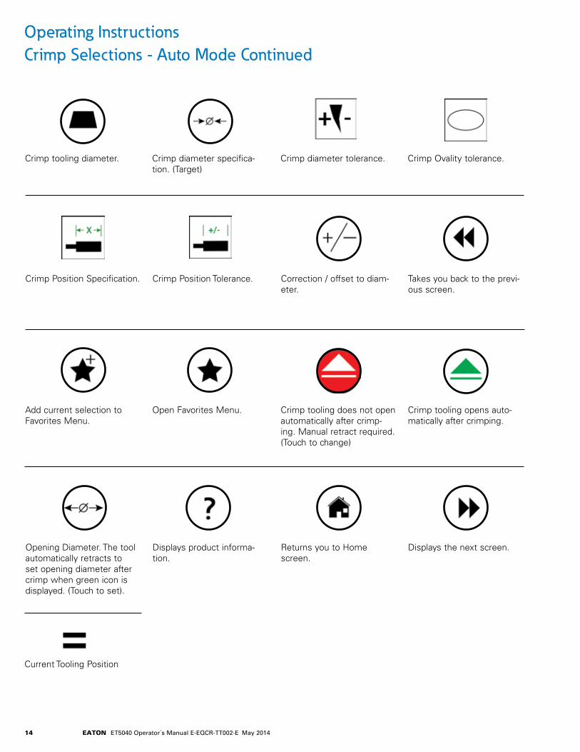
Operating Instructions Crimp Selections - Auto Mode Continued
Crimp tooling diameter .
Crimp Position Specification .
Add current selection to Favorites Menu .
Opening Diameter . The tool automatically retracts to set opening diameter after crimp when green icon is displayed . (Touch to set) .
Current Tooling Position
Crimp diameter tolerance .
Correction / offset to diam-eter .
Crimp tooling does not open automatically after crimp-ing . Manual retract required . (Touch to change)
Returns you to Home screen .
Crimp diameter specifica-tion . (Target)
Crimp Position Tolerance .
Open Favorites Menu .
Displays product informa-tion .
Crimp Ovality tolerance .
Takes you back to the previ-ous screen .
Crimp tooling opens auto-matically after crimping .
Displays the next screen .

15EATON ET5040 Operator´s Manual E-EQCR-TT002-E May 2014
Operating Instructions Manual Operation
Rotate the main power switch located on the right side of the machine to the “On” position. Wait for the machine to boot up . (See figure 25)
Follow the settings and calibration steps prior to initial production use of the machine (Page 18)
Note: Manual Operation is for crimping hose & fittings not in the pre-populated Eaton database .
Select “Manual Operation”. (See figure 26) Note: “Manual Operation” allows operator to enter and save their own desired crimp specifications .
Figure 25 Figure 26
Step 1 Step 2
Manual Operation Screen is shown in figure 27 . See expla-nation of all icon on page 16 . See operation sequence on page 18 .
Figure 27
Step 3

16 EATON ET5040 Operator´s Manual E-EQCR-TT002-E May 2014
Operating Instructions Manual Operation Continued
Icon Explanations:
Data entry field for naming custom crimp specification . Note: Entry not required for operation . Save required to retain for future use .
Offset for achieved diam-eter correction . Click icon to enter value .
Crimp diameter target (User defined via pop up numeri-cal keypad) .
Tooling diameter . Tooling auto populates, displaying suggested tooling for target crimp diameter . Note: User may input an alternate tool-ing selection .
Clears data entered from data entry field .
Set dwell time . (Time at fully closed position prior to auto open)
Set desired automatic retract opening diameter/position .
Note: The crimp tooling automatically retracts to this opening diameter only when green icon is displayed .
Auto Open Red - Off Green - On (Touch icon to change)
Quick die change: Initiates the die change, install sequence . (Touch to change) .
Additional inputs (to switch parameters) (Page 17)
Save data to user input data-base .
Return to “Home” screen.
Select number of pieces to crimp . Note: Not required to crimp . “0” selection will allow unlimited crimps .
Displays total number of pieces crimped so far .
Displays current position of crimp tooling/pressure of crimp .

17EATON ET5040 Operator´s Manual E-EQCR-TT002-E May 2014
Adjusting the Switching Point of the Crimp Machine
Adjust the switching point of the machine from closing speed to (slow) crimping speed in the “Switching Point” fields, either based on the displacement or the pressure .
The value first reached by the machine triggers switch-ing from closing to crimping speed .
Takes you back to the previ-ous screen .
Operational Steps1 . Define crimp specification in the appropriate field
2 . Reference the controller specified die required
3 . Load the appropriate dies utilizing the QDC button and instructions listed in this manual for safe die installation
4 . Verify uncrimped fitting diameter is smaller than the ‘switching point’ dimension (see Pg 18) . Adjust to adhere as needed .
5 . Set any desired dwell time to hold the crimp in the closed position before auto opening (if desired)
6 . Set the auto opening diameter (if desired)
7 . Safely locate the fitting properly within the crimp tooling
8 . Activate crimper by depressing the cycle start button on the controller or the foot pedal if activated, completing the crimp
9 . Measure the crimped fitting to proper specification
10 . If achieved crimp is larger or smaller than acceptable range, enter the needed numerical correction in the offset field (+/-) .
11 . Save the crimp setting under a user specified name (if desired) .
18 EATON ET5040 Operator´s Manual E-EQCR-TT002-E May 2014
Settings
Language
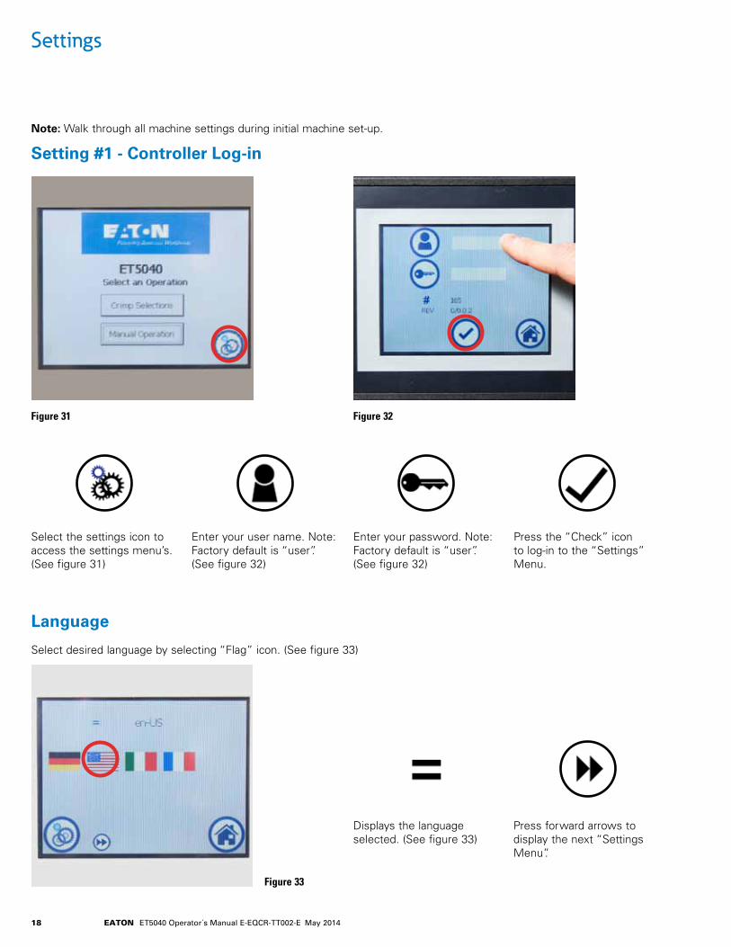
Setting #1 - Controller Log-in
Note: Walk through all machine settings during initial machine set-up .
Figure 31 Figure 32
Figure 33
Select desired language by selecting “Flag” icon. (See figure 33)
Displays the language selected . (See figure 33)
Enter your password . Note: Factory default is “user”. (See figure 32)
Select the settings icon to access the settings menu’s . (See figure 31)
Press the “Check” icon to log-in to the “Settings” Menu .
Enter your user name . Note: Factory default is “user”. (See figure 32)
Press forward arrows to display the next “Settings Menu”.

19EATON ET5040 Operator´s Manual E-EQCR-TT002-E May 2014
Software Version
Setting #2 - Display Units of Measurement
Settings
Figure 34
A B
Return to previous setting (Back)
Settings screen displays current software version loaded . (See figure 35)
No user adjustment or selection is needed .
Proceed to next setting (Forward)
Diameter settings and pres-sure units display menu . (See figure 34) Select unit of measurement for distance, press desired icon, “MM” or “Inches”.
Displays the selected unit of measurement in Millimeters or Inches .
Select unit of measurement for pressure, press desired icon, “Bar, PSI. or MPa”. (See figure 34)
Displays the selected unit of pressure measurement in “Bar, PSI.\, or MPa”. (See figure 34)
Figure 35
20 EATON ET5040 Operator´s Manual E-EQCR-TT002-E May 2014
Settings
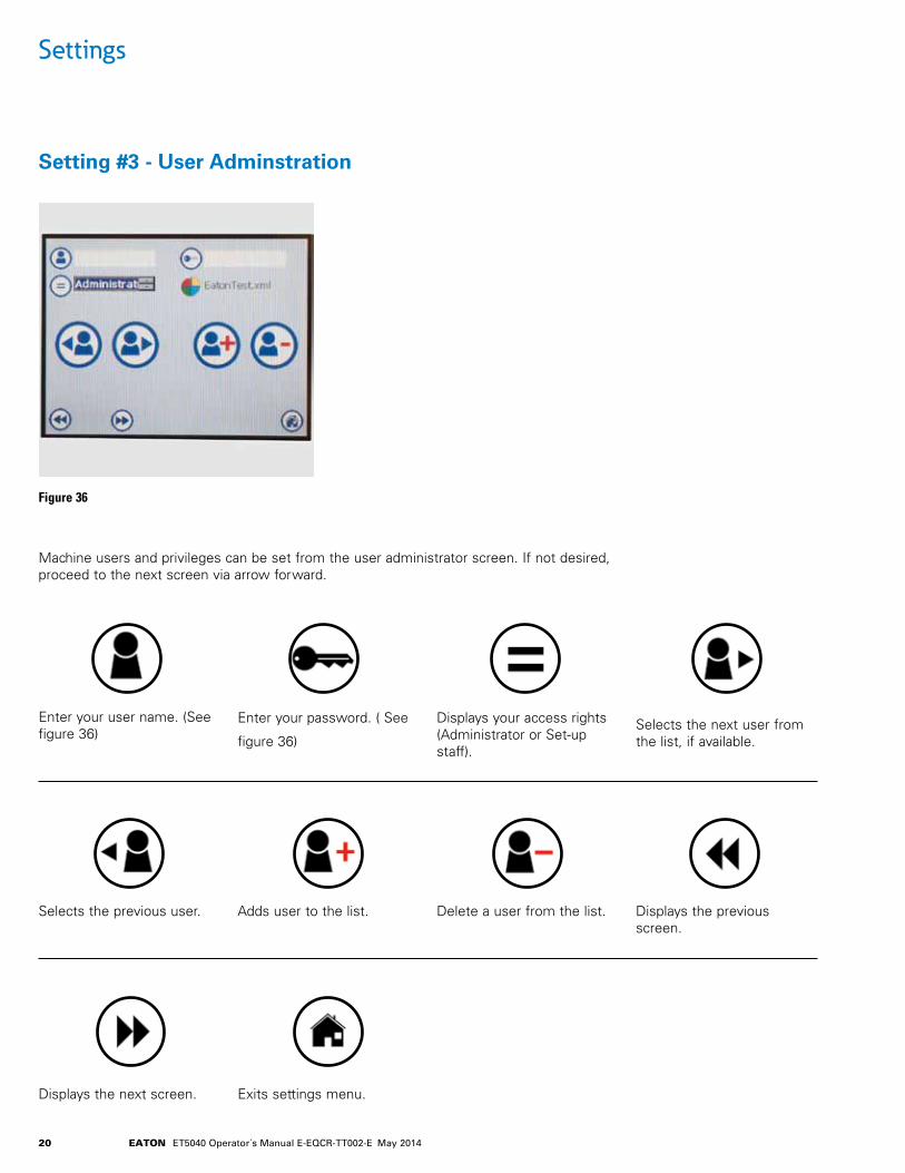
Setting #3 - User Adminstration
Figure 36
Enter your user name . (See figure 36)
Selects the previous user .
Enter your password . ( See
figure 36)
Adds user to the list .
Displays your access rights (Administrator or Set-up staff) .
Delete a user from the list .
Displays the next screen .
Selects the next user from the list, if available .
Displays the previous screen .
Exits settings menu .
Machine users and privileges can be set from the user administrator screen . If not desired, proceed to the next screen via arrow forward .

21EATON ET5040 Operator´s Manual E-EQCR-TT002-E May 2014
Setting #4 - Tooling Editor
Settings
Figure 37
Add a new die set to the list .
Proceed to next setting (for-ward) .
Delete a die set from the list .
Exit settings menu .
Restore complete Eaton tooling list .
Return to previous setting (back) .
Note: When the machine is delivered, the tooling editor contains all of the Eaton die sets . Remove the dies not pur-chased with the machine to direct the machine to the avail-able dies . (See figure 37)
Dies displayed by nominal size . Example: ET5040DC-M320S = 32 .0

22 EATON ET5040 Operator´s Manual E-EQCR-TT002-E May 2014
Setting #5 - Product/Operational Updates
Settings
Figure 38 Figure 39
Download from USB Install the USB device into the back of the controller and press the download icon, (See figure 39)
Exit settings menu .Upload to USB Upload to USB also available for product library backup and machine to machine transfer .
When complete and suc-cessful, an image with a green thumb up will pop up on the screen . Select the check mark to acknowledge .
If no updates are being loaded, step to next setting field via .
Updates will be provided via e-mail or online drop box stor-age . After downloading, store a copy of the files on an empty USB storage device in ‘FAT32’ format . Do not utilize the ‘Quick Format’ Option.
23EATON ET5040 Operator´s Manual E-EQCR-TT002-E May 2014
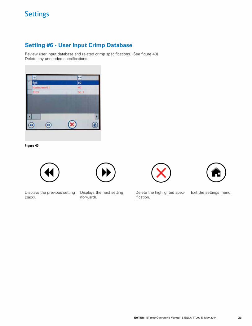
Setting #6 - User Input Crimp Database
Settings
Figure 40
Displays the previous setting (back) .
Displays the next setting (forward) .
Delete the highlighted spec-ification .
Exit the settings menu .
Review user input database and related crimp specifications . (See figure 40) Delete any unneeded specifications .

24 EATON ET5040 Operator´s Manual E-EQCR-TT002-E May 2014
Setting #7 - Machine Settings
Settings
Figure 41
Adjusted zero point and/or reference point of the machine . No user adjustment .
Exit settings menu .
Factory position for die change . No user adjustment .
Hydraulic motor run time after crimping . (Power saver function) . Adjustable by cus-tomer .
Total number of completed machine cycles (life of machine) .
Note: Most fields here are for reference only and should not be updated by the customer .
Displays the previous setting (back) .
Displays the next setting (forward) .

25EATON ET5040 Operator´s Manual E-EQCR-TT002-E May 2014
Setting #8 - Calibration Procedure
Settings
Adapter Dies and 32 mm Dies must be installed for calibra-tion procedure as directed . (See figure 42) Follow safe tooling installation instructions .
Press the motor on button to activate the hydraulic motor and then crimp onto the small end of the mandrel until the green light no longer is illuminated .
Install small end of mandrel as directed . (See figure 43 & 44) (ET5040C-0019 tool)
Figure 42 Figure 43
Figure 44
Motor On Advance
Keep Hands Clear Keep Hands Clear
Retract the crimp head until the large end mandrel loosely fits in . Rotate the calibration tool and insert the large end into the crimp head and advance the crimp tooling by depressing the advance button . (See figure 45) .
Figure 45
Retract Advance

26 EATON ET5040 Operator´s Manual E-EQCR-TT002-E May 2014
Setting #8 - Calibration Procedure Continued
Settings
When fully advanced, the advance button illumination will turn off indicating head is fully advance . The display screen will change showing calibration complete . (See figure 46) Fully retract head and remove calibration tool and press the enter button .
Figure 46

27EATON ET5040 Operator´s Manual E-EQCR-TT002-E May 2014
Maintenance
Power down the machine and lock out the main breaker prior to performing maintenance .
Daily Maintenance Procedures:
• Open the crimp tool completely .
• Power down the machine .
• Clean the master dies and crimp head of any foreign debris .
• Check visually for oil leakage . Wipe down any residue .
• Check the crimp head and associated parts for cracks, signs of damage and wear .
• Check the detent pins on the crimping dies for damage .
Monthly Maintenance
• Switch off the motor and switch off the machine on the main switch .
• Check the hydraulic hose assemblies and connections for leaks below the cabinet
• Check hydraulic oil level with the oil level stick attached to the vented cap by removing the front panel .
Six-month Maintenance
• Check the bearing plates for wear and galling . Worn bearing plates need to be exchanged .
• If replacement is required, contact customer service .
Annual Maintenance
• Switch off the motor and turn off the machine on the main switch .
• Pump out old oil and fill with 13 .2 gallons or 50 liters of new AW46 (ISO46) hydraulic fluid .
• Perform calibration procedure as detailed in settings #8 (page 25) .
Hydraulic Oil Change
• Fully open crimp head .
• Switch off & lock out power .
• Remove rear panel and pump out old oil from reservoir from the filler port .
• Refill with 50 liters (13 .2 Gallons) of AW46 hydraulic oil .
• Verify fill level with filler cap dip stick .
• Cycle crimp machine head and ventilate the crimp head per instructions on page 5 .
WARNING

28 EATON ET5040 Operator´s Manual E-EQCR-TT002-E May 2014
Accessories
Automatic Back Stop
Replaces controller activation of the crimper, hose must engage with back-stop to cycle the crimper . (See figure 47) Crimping stops whenever the hose no longer touches the back stop face .
Set actuation position of backstop prior to plugging into crimper .
Magnetic Work Light
Magnetic work light provides improved visibility in low light conditions . (See figure 51)
Table Top Die Storage Rack
Additional storage for standard size dies . (See figure 52)
Foot Switch
Optional foot switch is available for crimp head activation . (See figure 49) To activate foot switch, select button on controller .
Manual Back Stop
Used for position control . Locate assembly to desired position in crimp jaws . Adjust backstop to contact fitting assembly . (See figure 48)
Mirror
Provides operator with additional view-ing angles to assist in correct align-ment of crimp Position . (See figure 50)
Figure 47
Figure 51 Figure 52
Figure 49Figure 48
Figure 50
Retract Advance
29EATON ET5040 Operator´s Manual E-EQCR-TT002-E May 2014
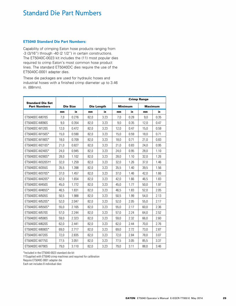
Standard Die Part Numbers
ET5040 Standard Die Part Numbers:
Capability of crimping Eaton hose products ranging from -3 (3/16”) through -40 (2 1/2”) in certain constructions. The ET5040C-0023 kit includes the (11) most popular dies required to crimp Eaton’s most common hose product lines . The standard ET5040DC dies require the use of the ET5040C-0001 adapter dies .
These die packages are used for hydraulic hoses and industrial hoses with a finished crimp diameter up to 3 .46 in . (88mm) .
Standard Die Set Part Numbers Die Size Die Length Minimum Maximum
mm in mm in mm in mm in
ET5040DC-M070S 7,0 0.276 82,0 3.23 7,0 0.28 9,0 0.35
ET5040DC-M090S 9,0 0.354 82,0 3.23 9,0 0.35 12,0 0.47
ET5040DC-M120S 12,0 0.472 82,0 3.23 12,0 0.47 15,0 0.59
ET5040DC-M150S* 15,0 0.590 82,0 3.23 15,0 0.59 18,0 0.71
ET5040DC-M180S* 18,0 0.709 82,0 3.23 18,0 0.71 21,0 0.83
ET5040DC-M210S* 21,0 0.827 82,0 3.23 21,0 0.83 24,0 0.95
ET5040DC-M240S* 24,0 0.945 82,0 3.23 24,0 0.95 28,0 1.10
ET5040DC-M280S* 28,0 1.102 82,0 3.23 28,0 1.10 32,0 1.26
ET5040DC-M320S†† 32,0 1.259 82,0 3.23 32,0 1.26 37,0 1.46
ET5040DC-M355S 35,5 1.398 82,0 3.23 35,5 1.40 39,5 1.56
ET5040DC-M370S* 37,0 1.457 82,0 3.23 37,0 1.46 42,0 1.66
ET5040DC-M420S* 42,0 1.654 82,0 3.23 42,0 1.66 46,5 1.83
ET5040DC-M450S 45,0 1.772 82,0 3.23 45,0 1.77 50,0 1.97
ET5040DC-M465S* 46,5 1.831 82,0 3.23 46,5 1.83 52,0 2.05
ET5040DC-M505S 50,5 1.988 82,0 3.23 50,5 1.99 54,0 2.13
ET5040DC-M520S* 52,0 2.047 82,0 3.23 52,0 2.05 55,0 2.17
ET5040DC-M550S* 55,0 2.165 82,0 3.23 55,0 2.17 60,0 2.36
ET5040DC-M570S 57,0 2.244 82,0 3.23 57,0 2.24 64,0 2.52
ET5040DC-M590S 59,0 2.323 82,0 3.23 59,0 2.32 66,0 2.60
ET5040DC-M620S 62,0 2.441 82,0 3.23 62,0 2.44 70,0 2.76
ET5040DC-M690S* 69,0 2.717 82,0 3.23 69,0 2.72 73,0 2.87
ET5040DC-M720S 72,0 2.835 82,0 3.23 72,0 2.84 78,0 3.07
ET5040DC-M775S 77,5 3.051 82,0 3.23 77,5 3.05 85,5 3.37
ET5040DC-M790S 79,0 3.110 82,0 3.23 79,0 3.11 88,0 3.46
*Included in the ET5040-0023 standard die kit††Supplied with ET5040 crimp machines and required for calibrationRequire ET5040C-0001 adapter dieEach set includes 8 individual dies
Crimp Range

30 EATON ET5040 Operator´s Manual E-EQCR-TT002-E May 2014
Large Bore Die Part Numbers
430 U-Series Part Numbers
ET5040 Large Bore Die Part Numbers:
Capability of crimping Eaton hose products ranging up to -64 (4”) in certain constructions. The large bore ET5040 dies do not require an adapter die and are inserted one segment at a time . The large bore dies are typically used for large I .D . Eaton Industrial hose and -48 two wire braid hose .
Standard Die Set Part Numbers Die Size Die Length Minimum Maximum
mm in mm in mm in mm in
ET5040PBL-M710 71,0 2.795 118,0 4,65 71,0 2.80 78,0 3.07
ET5040PBL-M740 74,0 2.913 118,0 4,65 74,0 2.92 83,0 3.26
ET5040PBL-M780 78,0 3.070 118,0 4,65 78,0 3.07 86,0 3.38
ET5040PBL-M840 84,0 3.307 118,0 4,65 84,0 3.31 92,0 3.62
ET5040PBL-M860 86,0 3.386 118,0 4,65 86,0 3.39 94,0 3.70
ET5040PBL-M900 90,0 3.543 118,0 4,65 90,0 3.55 99,0 3.89
ET5040PBL-M960 96,0 3.800 118,0 4,65 96,0 3.80 105,0 4.13
ET5040PBL-M1030 103,0 4.055 118,0 4,65 103,0 4.06 113,0 4.44
ET5040PBL-M1060 106,0 4.173 126,0 4.96 106,0 4.18 116,0 4.56
ET5040PBL-M1110 110,0 4.331 126,0 4.96 110,0 4.33 121,0 4.76
ET5040PBL-M1160 116,0 4.567 126,0 4.96 116,0 4.57 127,0 4.99
ET5040PBL-M1210 121,0 4.764 126,0 4.96 121,0 4.77 133,0 5.23
ET5040PBL-M1260 126,0 4.961 126,0 4.96 126,0 4.96 138,0 5.43
ET5040PBL-M1310 131,0 5.157 126,0 4.96 131,0 5.16 144,0 5.66
Crimp Range
Each set includes 8 individual dies
ET5040 430 “U” Series Die Part Numbers:
Capable of crimping Weatherhead 430 "U" series fittings ranging from -08 (1/2") through -32 (2") .
430 “U” Die Set Part Numbers
430 “U” Fitting Size Die Size Die Length Minimum Maximum
mm in mm in mm in mm in
ET5040DC-M210S 43006"U" Fittings 21,0 0.827 82,0 3.23 21,0 0.83 24,0 0.95
ET5040DC-08U* 43008"U" Fittings 28,0 1.102 82,0 3.23 28,0 1.10 32,0 1.26
ET5040DC-M280S 43010"U" Fittings 28,0 1.102 82,0 3.23 28,0 1.10 32,0 1.26
ET5040DC-12U* 43012"U" Fittings 32,0 1.259 82,0 3.23 32,0 1.26 36,0 1.41
ET5040DC-16U* 43016"U" Fittings 42,0 1.653 82,0 3.23 42,0 1.65 46,0 1.81
ET5040DC-20U* 43020"U" Fittings 52,0 2.047 82,0 3.23 52,0 2.05 57,0 2.24
ET5040DC-24U* 43024"U" Fittings 57,0 2.244 82,0 3.23 57,0 2.24 62,0 2.44
ET5040DC-32U* 43032"U" Fittings 69,0 2.716 82,0 3.23 69,0 2.72 75,0 2.95
Crimp Range
*Included in the ET5040-0022 430 “U” Series die kit Require ET5040C-0001 adapter dieEach set includes 8 individual dies

EatonHydraulics Group USA14615 Lone Oak RoadEden Prairie, MN 55344USATel: 952-937-9800Fax: 952-294-7722
EatonHydraulics Group EuropeRoute de la Longeraie 71110 MorgesSwitzerlandTel: +41 (0) 21 811 4600Fax: +41 (0) 21 811 4601
EatonHydraulics Group Asia PacificEaton BuildingNo .7 Lane 280 Linhong RoadChangning District,Shanghai 200335ChinaTel: (+86 21) 5200 0099Fax: (+86 21) 2230 7240
© 2014 Eaton All Rights Reserved Printed in USADocument No . E-EQCR-TT002-EMay 2014
Assembly EquipmentTechnical Support | Service | Spare Parts www .EatonCrimperSupport .com 1-888-AT-LOMAR (1-888-285-6627) (517-563-8800)


