32
Emergency Response Guide Eaton Hybrid Transmissions TRDR1100 EN-US October 2013

Emergency Response Guide
Eaton Hybrid TransmissionsTRDR1100 EN-USOctober 2013

Warnings and Cautions
trdr1100.book Page i Friday, October 11, 2013 3:55 PM
Warnings & Cautions
Throughout this manual there are paragraphs that are marked with a title of DANGER, WARNING, or CAUTION. These special paragraphs contain spe-cific safety information, and must be read, understood, and heeded before continuing the procedure, or performing the step(s).
DANGER: DANGER INDICATES YOU WILL BE SEVERLY INJURED OR KILLED IF YOU DO NOT FOLLOW THE INDICATED PROCEDURE
WARNING: WARNING INDICATES AN IMMEDIATE HAZARD, WHICH COULD RESULT IN SEVERE PERSONAL INJURY IF YOU DO NOT FOLLOW THE INDI-CATED PROCEDURE.
CAUTION: CAUTION INDICATES VEHICLE OR PROPERTY DAMAGE COULD OCCUR IF YOU DO NOT FOLLOW THE INDICATED PROCEDURE.
Note: NOTE INDICATES ADDITIONAL DETAIL THAT WILL AID IN THE DIAG-NOSIS OR REPAIR OF A COMPONENT/SYSTEM.
DANGERHAZARDOUS VOLTAGEYou will be severely injured or killedif you do not follow the procedure.Components marked with DANGER High Voltage should be avoided. Service must be performed by qualified personnel only.
WARNING
CAUTION
i

Warnings and Cautions
trdr1100.book Page ii Friday, October 11, 2013 3:55 PM
Read the entire driver instructions before operating this transmission.
Before starting a vehicle always be seated in the driver's seat, select “N” on the shift control, and set the parking brakes.
If engine cranks in any gear other than neutral, service your vehicle imme-diately!
The vehicle should never be worked on while in Hotel mode, since the engine can start.
Anytime you will be working on a vehicle, parking a vehicle, or leaving the cab with the engine running, place the transmission in neutral, set the parking brakes, and block the wheels.
For safety reasons, always engage the service brakes prior to selecting gear positions from "N".
Battery (+) and (-) must be disconnected prior to any type of welding on any Hybrid equipped vehicle.
It is a requirement that the driver of a commercial vehicle specified under paragraph A sections 1-6 of FMCSA regulation 392.10 must only cross rail-road grade crossings in a gear that permits the vehicle to complete the crossing without a change of gears.
This can only be achieved by utilizing the Manual “M” mode. Please refer to the “Manual Mode” section in the book for correct operation.
WARNING
CAUTIONCAUTION
IMPORTANTIMPORTANT
ii

Warnings and Cautions
trdr1100.book Page iii Friday, October 11, 2013 3:55 PM
High-Voltage Warnings & Cautions
Use CO2 or Dry Chemical Fire Extinguishers. The battery or batteries in the Power Electronics carriers (PEC) are Lithium ion.
The high-voltage wiring is covered in orange insulation or convoluted tub-ing and marked with warning labels at the connectors.
All Eaton® Hybrid Diesel/Electric vehicles will be marked 'Hybrid' on the outside of the vehicle, as well as the shift label on the dash.
Do NOT cut into or remove any of the orange high-voltage cables. Refer to the high-voltage diagram in the vehicle.
Do NOT cut into or open the PEC. Refer to the high-voltage diagram in vehi-cle.
Do NOT cut into or open the DC/DC converter. Refer to the high-voltage dia-gram in the vehicle.
Do NOT cut into or open the Inverter. Refer to the high-voltage diagram in the vehicle.
Do NOT work on a Eaton Hybrid vehicle until it has be properly powered down. Refer to the ‘Emergency Shutdown Procedures’ section.
The high-voltage system may remain powered for up to 5 minutes after the vehicle is shut off or disabled. To prevent serious injury or death from severe burns or electric shock, avoid touching any high-voltage cable/com-ponent for a minimum of 5 minutes.
The “Emergency Shutdown Procedures" section of this manual explains how to power down in an emergency.
WARNINGTo reduce risk of possible serious injury (Shock, Burn or Death): Components marked with High Voltage should be avoided. Service must be performed by qualified personnel only.
HAZARDOUS VOLTAGE
DANGERHAZARDOUS VOLTAGEYou will be severely injured or killedif you do not follow the procedure.Components marked with DANGER High Voltage should be avoided. Service must be performed by qualified personnel only.
iii

Warnings and Cautions
trdr1100.book Page iv Friday, October 11, 2013 3:55 PM
iv

Table of Contents
Warnings & Cautions ............................................................................. i
Foreword ............................................................................................... 1
Identifying a Hybrid Vehicle................................................................... 2
High-Voltage Batteries......................................................................... 13
Built-In Safety Features ....................................................................... 15
Hybrid System Emergency Procedures ............................................... 16
Recycling and Emergency Contact Information for the Lithium Ion
Batteries .............................................................................................. 23
Do’s and Don’ts................................................................................... 24
Vehicle Towing and Jumpstarting ....................................................... 25
trdr1100.book Page 0 Friday, October 11, 2013 3:55 PM

1
Foreword
Foreword
This manual has been created to assist the first responders in identifying and responding to vehicles equipped with Eaton® Hybrid systems. Emergency response procedures are similar to current methods used for non-Hybrid trucks.
The Eaton Hybrid system equipped vehicle uses high-voltage AC to power an electric motor in combination with a diesel engine to improve fuel economy and reduce emissions. A high-voltage battery pack stores energy until it is required to power the vehicle. Some applications also use a DC/DC Converter to maintain the 12v batteries during engine off PTO mode.
The Eaton Hybrid system has been designed with many features for user protection, to ensure safe access to and from the vehicle under various conditions. It is important to read and understand the “Emergency Shutdown Procedures”, and you should ALWAYS assume the vehicle is powered up.
trdr1100.book Page 1 Friday, October 11, 2013 3:55 PM

Identification
trdr1100.book Page 2 Friday, October 11, 2013 3:55 PM
Identifying a Hybrid Vehicle
Identification
There are several methods to identify a vehicle equipped with an Eaton® Hybrid system.
• First, the outside of an Eaton Hybrid vehicle will contain the word “HYBRID.”
• Second, the shift label located on the dash states “Eaton Hybrid Transmission.”
• And last, the vehicle will have a large orange cable going to the transmission along with several other components mounted to the frame rails towards the front of the vehicle.
2

Identification
trdr1100.book Page 3 Friday, October 11, 2013 3:55 PM
Component Description and Location
All vehicles equipped with an Eaton Hybrid system will contain a high-voltage location diagram in the truck cab for reference. The following components comprise the Eaton Hybrid system.
Component Location Description
Motor / Generator Mounted between engine and transmission
3-phase AC high-voltage permanent magnet Motor/Generator
Motor/GeneratorMotor/Generator
Motor/Generator
Models EH-XXXXXA-XXX and EH-XXXXXXA-XXX
3

Identification
trdr1100.book Page 4 Friday, October 11, 2013 3:55 PM
Component Description and Location
All vehicles equipped with an Eaton Hybrid system will contain a high-voltage location diagram in the truck cab for reference. The following components comprise the Eaton Hybrid system.
Component Location Description
Motor / Generator Mounted between engine and transmission
3-phase AC high-voltage permanent magnet Motor/Generator
Motor/Generator
Motor/Generator
Motor/Generator
Models EH-XXXXXB-XXX and EH-XXXXXXB-XXX
4

Identification
trdr1100.book Page 5 Friday, October 11, 2013 3:55 PM
Component Location Description
MY08 Inverter Frame rail near cab or bed mounted depending on OEM.
Inverts high-voltage DC to 3-phase AC to power the Motor / Generator and rectifies AC to DC to recharge the high-voltage batteries.
HIgh Voltage 3-Way AC Connector
Low Voltage 56-Way Connector High-Voltage DC Connector to PEC
Inverter
Coolant Port InletCoolant Port Outlet
5

Identification
trdr1100.book Page 6 Friday, October 11, 2013 3:55 PM
Component Location Description
MY09 Inverter Frame rail near cab or bed mounted depending on OEM.
Inverts high-voltage DC to 3-phase AC to power the Motor / Generator and rectifies AC to DC to recharge the high-voltage batteries.
HIgh-Voltage 3-Way AC Connector
Low-Voltage 40-Way ConnectorHigh-Voltage DC Connector to PEC
Coolant Port InletCoolant Port Outlet
6

Identification
trdr1100.book Page 7 Friday, October 11, 2013 3:55 PM
Component Location Description
MY08 Power Electronics Carrier (PEC)
Frame rail near cab or bed mounted depending on OEM.
Contains the high-voltage batteries, wiring and relays. 2 sealed Lithium Ion batteries connected in series produce 340 volts.
Red Service Switch with Cover
DC Connectorto Inverter
DC Connector to DC/DC Converter
DC Connector toAPG (Optional)
Air Exhaust(not shown)
19-Pin Low-Voltage Connector
Air Intake
7
Identification
trdr1100.book Page 8 Friday, October 11, 2013 3:55 PM
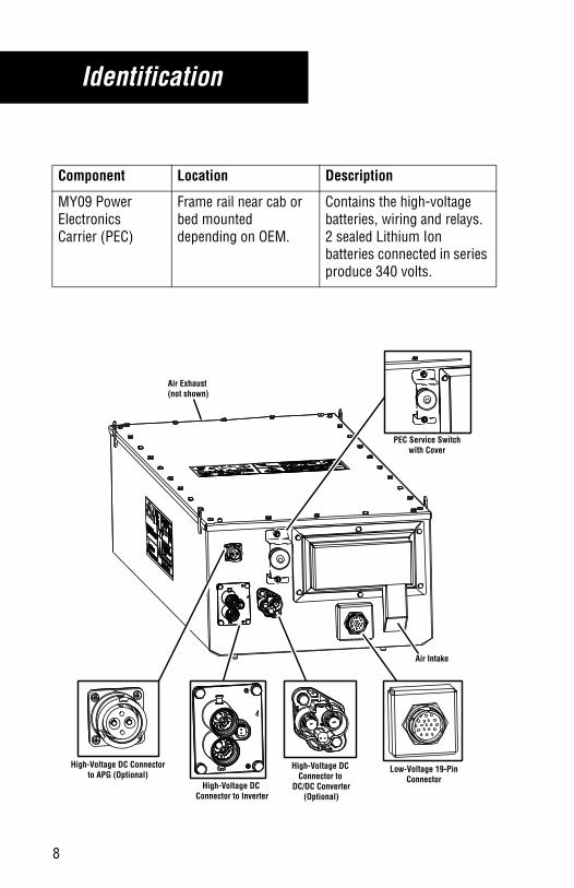
Component Location Description
MY09 Power Electronics Carrier (PEC)
Frame rail near cab or bed mounted depending on OEM.
Contains the high-voltage batteries, wiring and relays. 2 sealed Lithium Ion batteries connected in series produce 340 volts.
PEC Service Switchwith Cover
High-Voltage DC Connector to
DC/DC Converter(Optional)
High-Voltage DC Connectorto APG (Optional)
Air Exhaust(not shown)
Low-Voltage 19-PinConnector
Air Intake
High-Voltage DC Connector to Inverter
8

Identification
trdr1100.book Page 9 Friday, October 11, 2013 3:55 PM
Component Location Description
4-Battery Power Electronics Carrier (PEC)
Frame rail near cab or bed mounted depending on OEM.
Contains the high-voltage batteries, wiring and relays. 4 sealed Lithium Ion batteries connected in series produce 340 volts.
Air Filter Cover Wing Nuts
Exhaust Duct
PEC Service Switch Access Panel Covers
Access Panel Security Screws
Low-Voltage 19-Pin Connector
Top Cover
Air Filter Cover
High-Voltage DC Connector to Inverter
Air Outlet
Access Panel (On side not shown)
Cooling Pipes
(8) Mounting Holes (Mounting hardware supplied by OEM)
Cover Bolts
Lifting EyesCover Security Screws
9

Identification
trdr1100.book Page 10 Friday, October 11, 2013 3:55 PM
Component Location Description
Altenative Power Electronics Carrier (PEC)
Frame rail near cab or bed mounted depending on OEM.
Contains the high-voltage batteries, wiring and relays. 96 Lithium Ion polymer cells connected in series to produce 360 volts.
Front
Rear
High-Voltage DCConnector to Inverter
Low-Voltage 19-Pin Connector
Mechanical Service Disconnect
10

Identification
trdr1100.book Page 11 Friday, October 11, 2013 3:55 PM
DC High-Voltage Connector
Component Location Description
High-Voltage Wiring
Frame rail and transmission mounted. Some applications have body mounted cables if the components are located the truck bed.
Orange colored power cables that carry high- voltage AC (500v) and high-voltage DC (340v). Cables are connected to the Motor/Generator, Inverter, PEC, DC/DC Converter (Optional), and APG (Optional).
11
Identification
trdr1100.book Page 12 Friday, October 11, 2013 3:55 PM
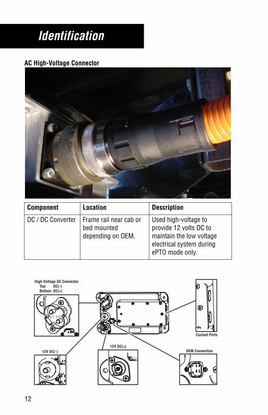
AC High-Voltage Connector
Component Location Description
DC / DC Converter Frame rail near cab or bed mounted depending on OEM.
Used high-voltage to provide 12 volts DC to maintain the low voltage electrical system during ePTO mode only.
12V DC(-)
High-Voltage DC Connector Top: DC(-) Bottom: DC(+)
OEM Connection
Coolant Ports
12V DC(+)
(-) (+)
12

High-Voltage Batteries
trdr1100.book Page 13 Friday, October 11, 2013 3:55 PM
MY08/MY09, 4-Battery, and Alternative PEC High-Voltage Batteries
The high-voltage batteries are located inside the Power Electronics Carrier (PEC). The MY08 PEC is a plastic composite shell with a metal reinforcement. The MY09, 4-Battery, and Alternative PECs are metal shell compositions. The mountings of the PECs are currently frame rail mounted or bed mounted options.
The MY08, MY09, and 4-battery PEC contain two or four high-voltage batter-ies that are connected in series with each battery producing 172 volts. Each battery consists of 48 individual cells that contain 3.6 volts and are connected in series to produce 172 volts.
Each cell is contained in a sealed container. The batteries contain Lithium Manganese Oxide. The electrolyte used in the battery is a Lithium Salt in an organic solvent.
The alternative PEC contains 96 individual Lithium Ion polymer cells that con-tain 3.75 volts connected in series producing 360 volts.
If skin comes in contact with electrolyte wash skin with soap and water.
If eyes come in contact with electrolyte immediately wash eyes with water for 15 minutes and seek medical attention.
MY08/MY09 and 4-Battery PEC Battery Composition• Chemical system: Lithium Manganese Oxide (Partially substituted by
nickel and cobalt)/Carbon. (Li-Mn-Ni-Co-O / C).• Electrolyte: Lithium Salt in an Organic Solvent (non-aqueous liquid).
The electrolyte is absorbed into 48 individual cells per battery and will not normally spill or leak if the battery is damaged.
• If electrolyte leaks from a cell, use a towel to wipe it up.• Max Electrolyte for 2-Battery system is 4000cc (1.2 Gallons).• Max Electrolyte for 4-Battery system is 8000cc (2.4 Gallons).
13

High-Voltage Batteries
trdr1100.book Page 14 Friday, October 11, 2013 3:55 PM
Alternative PEC Battery Composition• Lithium Ion polymer technology.• Safety reinforced separator (SRS).• Prismatic laminated package.• 96 individual cells containing a proprietary metal.• Max Electrolyte is proprietary.
WARNING: The batteries should be kept away from heat, ignition sources, and water.
WARNING
14

15
Built-In Safety Features
Built-In Safety Features
All high-voltage cables are covered in orange insulation and clearly labeled near each connector end. Each high-voltage component is clearly tagged with a warning or danger label.
A high-voltage fuse located in the Power Electronics Carrier (PEC) provides protection in high-voltage battery system.
The high-voltage cables coming from the PEC are controlled by relays that are normally open. When the ignition key is turned off, the relays open, which contains the voltage inside the Power Electronics Carrier (PEC).
All positive and negative high-voltage cables are isolated from the metal chassis to prevent shock by touching the metal chassis.
A ground fault monitor continuously checks for high-voltage leakage to the metal chassis while the vehicle is running. If a malfunction is detected the Amber “Check Hybrid” lamp is lit, and the high-voltage system is shut off.
An inertia switch mounted in the MY08 and MY09 PECs will open the high-voltage relay circuit in the event of an accident.
All high-voltage DC cables contain an Interlock loop that will shut down the high-voltage system if they become loose or disconnected.
The AC cable is continuously monitored to detect an open or short to ground fault. If a fault is detected at key on the vehicle will not crank. If the vehicle is moving the red ‘Stop Hybrid’ lamp will illuminate.
DANGERHAZARDOUS VOLTAGEYou will be severely injured or killedif you do not follow the procedure.Components marked with DANGER High Voltage should be avoided. Service must be performed by qualified personnel only.
WARNINGTo reduce risk of possible serious injury (Shock, Burn or Death): Components marked with High Voltage should be avoided. Service must be performed by qualified personnel only.
HAZARDOUS VOLTAGE
trdr1100.book Page 15 Friday, October 11, 2013 3:55 PM

Emergency Procedures
trdr1100.book Page 16 Friday, October 11, 2013 3:55 PM
Hybrid System Emergency Procedures
High-Voltage ShutdownNote: After disabling the vehicle, power is maintained up to 5 minutes in
the high-voltage electrical system.
Option 1 (Preferred) Turn Ignition Key off on Dash
1. Engine will shut down.2. Dash lights will shut down.3. HEV system will shut down.4. HEV batteries are still “live” but are isolated in the PEC.
Option 2 Disconnect Low Voltage (12v) Vehicle Batteries
1. Engine will shut down.2. Dash lights will shut down.3. HEV system will shut down.4. HEV batteries are still “live” but are isolated in the PEC.
Note: If applicable, the service switch on the PEC may be pushed in, which will shut down the HEV system and isolate the “live” HEV batteries in the PEC.
The high-voltage system may remain powered for up to 5 minutes after the vehicle is shut off or disabled. To prevent serious injury or death from severe burns or electric shock, avoid touching any high-voltage cable/com-ponent for a minimum of 5 minutes.
If you will be working around or removing any high-voltage cables or com-ponents, you MUST use Class 0 insulated rubber gloves.
WARNING
16

Emergency Procedures
trdr1100.book Page 17 Friday, October 11, 2013 3:55 PM
Emergency Procedure in Case of Accident or Extrica-tion
1. Ensure the wheels are chocked.2. Follow one of the ‘Emergency Shutdown Procedures’. After dis-
abling the vehicle, power is maintained up to 5 minutes in the high-voltage electrical system
3. Use Class 0 insulated rubber gloves to work on or near any of the high-voltage wiring or components.
4. If the vehicle must be altered to gain access, ensure that you check to make sure you won’t cut or puncture a high-voltage component
5. If the batteries are damaged, such that a spill is present refer to the “Emergency Procedures for Spills” section.
The high-voltage wiring is covered in orange insulation or convoluted tub-ing and marked with warning labels at the connectors.
All Eaton® Hybrid Diesel/Electric vehicles will be marked 'Hybrid' on the outside of the vehicle, as well as the shift label on the dash.
Do NOT cut into or remove any of the orange high-voltage cables. Refer to the high-voltage diagram in the vehicle.
Do NOT cut into or open the PEC. Refer to the high-voltage diagram in vehi-cle.
Do NOT cut into or open the DC/DC converter. Refer to the high-voltage dia-gram in the vehicle.
Do NOT cut into or open the Inverter. Refer to the high-voltage diagram in the vehicle.
Do NOT work on a Eaton Hybrid vehicle until it has be properly powered down. Refer to the ‘Emergency Shutdown Procedures’ section.
WARNING
17

Emergency Procedures
trdr1100.book Page 18 Friday, October 11, 2013 3:55 PM
The high-voltage system may remain powered for up to 5 minutes after the vehicle is shut off or disabled. To prevent serious injury or death from severe burns or electric shock, avoid touching any high-voltage cable/com-ponent for a minimum of 5 minutes.
If you will be working around or removing any high-voltage cables or com-ponents, you MUST use Class 0 insulated rubber gloves.
18

Emergency Procedures
trdr1100.book Page 19 Friday, October 11, 2013 3:55 PM
Emergency Procedure in Case of Fire
If the vehicle becomes involved in a fire:
1. Use self-contained breathing apparatus (SCBA).2. Battery fire - Dry chemical (ABC), carbon dioxide (CO2), or fire extin-
guishers rated for class D fires 3. Follow one of the ‘Emergency Shutdown Procedures’. After dis-
abling the vehicle, power is maintained up to 5 minutes in the high-voltage electrical system
The high-voltage wiring is covered in orange insulation or convoluted tub-ing and marked with warning labels at the connectors.
All Eaton® Hybrid Diesel/Electric vehicles will be marked 'Hybrid' on the outside of the vehicle, as well as the shift label on the dash.
All Eaton Hybrid Diesel/Electric vehicles will contain a high-voltage compo-nent location diagram in the truck.
Do NOT cut into or remove any of the orange high-voltage cables. Refer to the high-voltage diagram in the vehicle.
Do NOT cut into or open the PEC. Refer to the high-voltage diagram in vehi-cle.
Do NOT cut into or open the DC/DC converter. Refer to the high-voltage dia-gram in the vehicle.
Do NOT cut into or open the Inverter. Refer to the high-voltage diagram in the vehicle.
Do NOT work on a Eaton Hybrid vehicle until it has be properly powered down. Refer to the ‘Emergency Shutdown Procedures’ section.
WARNING
19

Emergency Procedures
trdr1100.book Page 20 Friday, October 11, 2013 3:55 PM
Emergency Procedure for Submerged or Partially Submerged VehicleNote: There is no risk of electric shock from touching the vehicle’s body or
framework - in or out of the water. The entire high-voltage system is iso-lated from the vehicle chassis.
1. Remove the vehicle from the water.2. Drain water from vehicle if possible.3. Ensure wheels are chocked.4. Follow one of the ‘Emergency Shutdown Procedures’. After dis-
abling the vehicle, power is maintained up to 5 minutes in the high-voltage electrical system
5. Use Class 0 insulated rubber gloves to work on or near any of the high-voltage wiring or components.
WARNING: The batteries should be kept away from heat, ignition sources, and water.
Emergency Procedure for Spills
The high-voltage battery or batteries contain an organic solvent. The electro-lyte will not normally spill or leak if the PEC is damaged. If the electrolyte is spilled, wipe up the spill with a towel and dispose of properly.
Note: Refer to “First Aid” section if you do come in contact with the battery contents.
Wear protective equipment:• Safety glasses• Rubber gloves rated for Class 0• Towel• Respiratory protection
WARNING
20

Emergency Procedures
trdr1100.book Page 21 Friday, October 11, 2013 3:55 PM
MY08/MY09 and 4-Battery PEC Battery Composition• Chemical system: Lithium Manganese Oxide (Partially substituted by
nickel and cobalt)/Carbon. (Li-Mn-Ni-Co-O / C).• Electrolyte: Lithium Salt in an Organic Solvent (non-aqueous liquid).
The electrolyte is absorbed into 48 individual cells per battery and will not normally spill or leak if the battery is damaged.
• If electrolyte leaks from a cell, use a towel to wipe it up.• Max Electrolyte for 2-Battery system is 4000cc (1.2 Gallons).• Max Electrolyte for 4-Battery system is 8000cc (2.4 Gallons).
Alternative PEC Battery Composition• Lithium Ion polymer technology.• Safety reinforced separator (SRS).• Prismatic laminated package.• 96 individual cells containing a proprietary metal.• Max Electrolyte is proprietary.
21

Emergency Procedures
trdr1100.book Page 22 Friday, October 11, 2013 3:55 PM
First Aid
Exposure to electrolyte is very unlikely except in a catastrophic crash or through improper handling. Follow the guidelines below in the event of expo-sure.
Absorption
• Skin Contact Remove contaminated clothing and rinse affected area with soap and water for 20 minutes.
• Eye Contact If eyes come in contact with electrolyte wash eyes for 15 minutes with water.
Inhalation Non-Fire Situations
• No toxic gases are emitted under normal conditions
Inhalation Fire Situations
• Toxic gases are produced from combustion by-products. All responders should wear the proper PPE for fire including SCBA. Move patient from hazardous environment to safe area to administer oxygen, then transport to hospital.
22

23
Emergency Procedures
Recycling and Emergency Contact Information for theLithium Ion BatteriesEmergency Contact InformationDuring an emergency, Eaton Material Safety Data Sheets (MSDS) may be requested by contacting 3E.
Call -• Americas (US, Canada, Mexico, South America): 1-760-476-3962• Europe, Middle East and Africa: 1-760-476-3961• Asia Pacific: 1-760-476-3960
You will need to following when calling 3E:• COMPANY: Eaton Corporation (REQUIRED)• COMPANY CODE: 333100
RecyclingFor information regarding recycling of the high-voltage battery pack located in the Power Electronics Carrier (PEC), contact Eaton at 1-800-826-HELP (4357).
trdr1100.book Page 23 Friday, October 11, 2013 3:55 PM
24
Do’s and Don’ts
Do’s and Don’ts
Do’s• Always assume the vehicle is “live” when you approach a Hybrid.• Always perform one of the three “Emergency Shutdown Procedures”
and allow the vehicle to set for 5 minutes prior to working on a Hybrid
Don’ts• Never work on the vehicle if you haven’t performed one of the three
“Emergency Shutdown Procedures” and allowed the vehicle to set for 5 minutes
• If at all possible, never cut the orange high-voltage cables• If at all possible never cut into or open the Inverter, PEC, or DC/DC
Converter
trdr1100.book Page 24 Friday, October 11, 2013 3:55 PM

25
Vehicle Towing
Vehicle Towing and Jumpstarting
When towing the vehicle, the output shaft of the transmission must not be allowed to spin or turn. If the vehicle is towed with the drive wheels still in contact with the road surface, the vehicle axle shafts or driveline must be removed or disconnected.
Serious Internal transmission damage can result from improper vehicle towing.
Jumpstarting (12 volt)
Jump starting vehicles equipped with the Eaton® Hybrid System is identical to Non-Hybrid vehicles, which uses the vehicle 12 volt battery system.
WARNING
Correct
INCORRECT
trdr1100.book Page 25 Friday, October 11, 2013 3:55 PM

Copyright Eaton, 2013.Eaton hereby grant their customers,vendors, or distributors permissionto freely copy, reproduce and/ordistribute this document in printedformat. It may be copied only inits entirety without any changes ormodifications. THIS INFORMATIONIS NOT INTENDED FOR SALE ORRESALE, AND THIS NOTICE MUSTREMAIN ON ALL COPIES.
Note: Features and specificationslisted in this document are subject tochange without notice and representthe maximum capabilities of thesoftware and products with all optionsinstalled. Although every attempt hasbeen made to ensure the accuracy ofinformation contained within, Eatonmakes no representation about thecompleteness, correctness or accuracyand assumes no responsibility forany errors or omissions. Features andfunctionality may vary depending onselected options.
For spec’ing or service assistance, call 1-800-826-HELP (4357) or visit www.eaton.com/roadranger.In Mexico, call 001-800-826-4357.
EatonVehicle GroupP.O. Box 4013Kalamazoo, MI 49003 USA800-826-HELP (4357)www.eaton.com/roadranger
Printed in USA
Roadranger: Eaton and trusted partners providing the best products and services in the industry, ensuring more time on the road.
www.eaton.com/greensolutions


