16
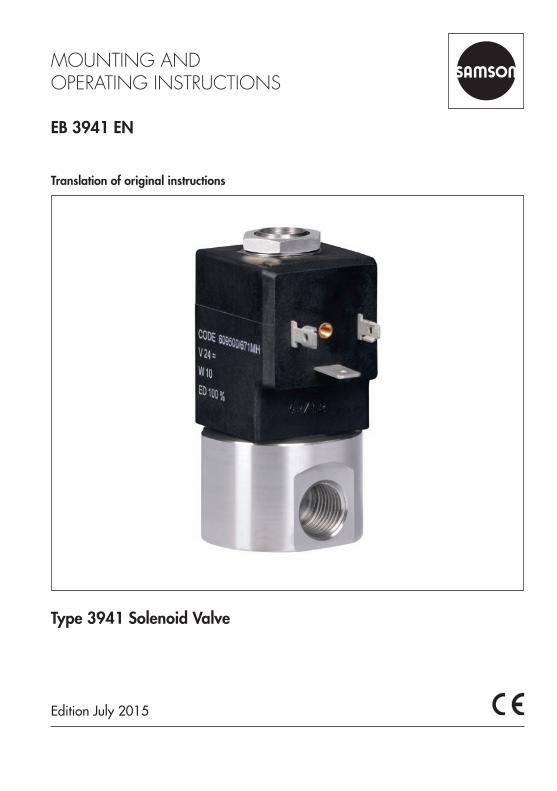
Translation of original instructions EB 3941 EN Edition July 2015 Type 3941 Solenoid Valve
| Date post: | 12-Dec-2018 |
| Category: |
Documents |
| Upload: | nguyenngoc |
| View: | 216 times |
| Download: | 0 times |
Translation of original instructions
EB 3941 EN
Edition July 2015
Type 3941 Solenoid Valve
Note on these mounting and operating instructions
These mounting and operating instructions assist you in mounting and operating the device safely. The instructions are binding for handling SAMSON devices.
Î For the safe and proper use of these instructions, read them carefully and keep them for later reference.
Î If you have any questions about these instructions, contact SAMSON‘s After-sales Service Department ([email protected]).
The mounting and operating instructions for the devices are included in the scope of delivery. The latest documentation is available on our website at www.samson.de > Service & Support > Downloads > Documentation.
Definition of signal words
Hazardous situations which, if not avoided, will result in death or serious injury
Hazardous situations which, if not avoided, could result in death or serious injury
Property damage message or malfunction
Additional information
Recommended action
DANGER!
WARNING!
NOTICE!
Note
Tip
2 EB 3941 EN
Contents
EB 3941 EN 3
1 General safety instructions .............................................................................41.1 Legal information ...........................................................................................42 Markings on the device .................................................................................52.1 Nameplate ....................................................................................................52.2 Article code ...................................................................................................63 Design and principle of operation ..................................................................73.1 Technical data ...............................................................................................83.2 Dimensions in mm ..........................................................................................94 Mounting and start-up .................................................................................104.1 Mounting position ........................................................................................105 Medium connection .....................................................................................106 Electrical connection ....................................................................................116.1 Sizing of the connecting line .........................................................................117 Accessories .................................................................................................12

4 EB 3941 EN
General safety instructions
1 General safety instructions − The device is to be mounted, started up or operated only by trained and experienced
personnel familiar with the product.According to these mounting and operating instructions, trained personnel refers to indi-viduals who are able to judge the work they are assigned to and recognize possible dan-gers due to their specialized training, their knowledge and experience as well as their knowledge of the applicable standards.
− The supply air must not exceed the maximum permissible supply pressure and must be limited by pressure reducing valve, if necessary.
− Proper shipping and storage are assumed.
1.1 Legal informationThe Type 3941 Solenoid Valve bears a CE marking. The declaration of conformity includes information about the applied conformity assessment procedure.

EB 3941 EN 5
Markings on the device
2 Markings on the device
2.1 Nameplate
SAMSON 3941Solenoid valve UN = Air Supply max. 10 bar / 150 psiModel 3941 - 000
Var.-ID
Serial no.
Made in GermanySAMSON AG D-60314 Frankfurt
1
2
3
4
5
1 Nominal signal2 Article code3 Configuration ID4 Serial number5 Compliance

6 EB 3941 EN
General safety instructions
2.2 Article codeSolenoid valve Type 3941- 0 0 0 x 0 x 1 0 1 0 0 0 0 0 0 0 0 0Nominal signal 24 V DC 3
230 V AC 5Manual override Without 0Switching function 3/2-way function 0
2/2-way function 1Attachment Threaded connection for wall or pipe
mounting1
KVS coefficient 0.16 0Pneumatic connection G 1/4 1Body material Stainless steel 0Gasket material NBR 0Electrical connection Connector according to DIN EN 175301-803,
type A, three-pole (without cable socket)0
Degree of protection IP 65 0Permissible ambient temperature –10 to +50 °C 0
EB 3941 EN 7
Design and principle of operation
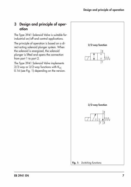
3 Design and principle of oper-ation
The Type 3941 Solenoid Valve is suitable for industrial on/off and control applications.The principle of operation is based on a di-rect-acting solenoid plunger system. When the solenoid is energized, the solenoid plunger is lifted and opens the connection from port 1 to port 2.The Type 3941 Solenoid Valve implements 2/2-way or 3/2-way functions with KVS 0.16 (see Fig. 1) depending on the version.
Fig. 1: Switching functions
1
2
1
2
3
3/2-way function
2/2-way function
8 EB 3941 EN
Design and principle of operation
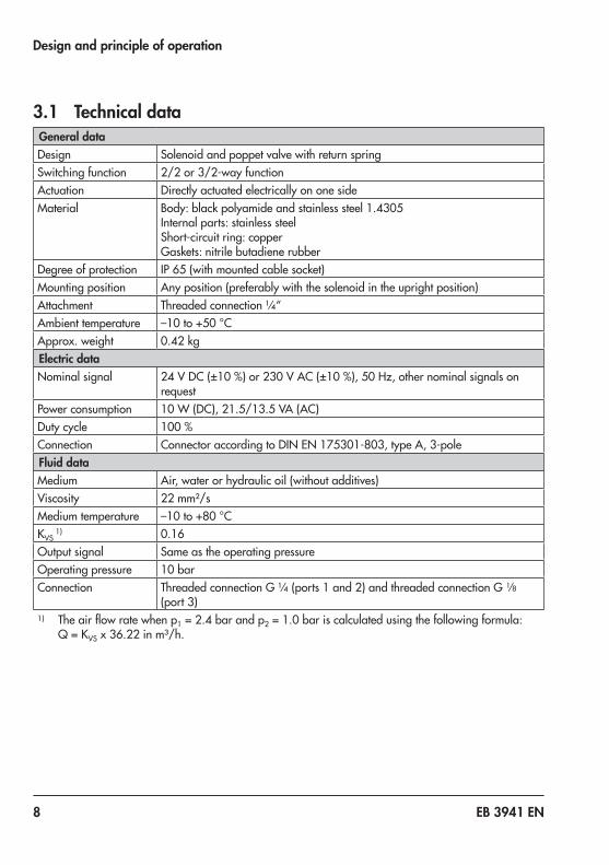
3.1 Technical dataGeneral dataDesign Solenoid and poppet valve with return springSwitching function 2/2 or 3/2-way functionActuation Directly actuated electrically on one sideMaterial Body: black polyamide and stainless steel 1.4305
Internal parts: stainless steel Short-circuit ring: copper Gaskets: nitrile butadiene rubber
Degree of protection IP 65 (with mounted cable socket)Mounting position Any position (preferably with the solenoid in the upright position)Attachment Threaded connection ¼“Ambient temperature –10 to +50 °CApprox. weight 0.42 kgElectric dataNominal signal 24 V DC (±10 %) or 230 V AC (±10 %), 50 Hz, other nominal signals on
requestPower consumption 10 W (DC), 21.5/13.5 VA (AC)Duty cycle 100 %Connection Connector according to DIN EN 175301-803, type A, 3-poleFluid dataMedium Air, water or hydraulic oil (without additives)Viscosity 22 mm²/sMedium temperature –10 to +80 °CKVS
1) 0.16Output signal Same as the operating pressureOperating pressure 10 barConnection Threaded connection G ¼ (ports 1 and 2) and threaded connection G 1/8
(port 3)1) The air flow rate when p1 = 2.4 bar and p2 = 1.0 bar is calculated using the following formula:
Q = KVS x 36.22 in m³/h.
EB 3941 EN 9
Design and principle of operation
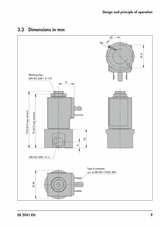
3.2 Dimensions in mm73
(3/2
-way
ver
sion)
2125
8
75.8
(2/2
-way
ver
sion)
DIN ISO 228-1 G ¼
Blanking plugDIN ISO 228-1 G 1/8
Ø 3
8
Type A connectoracc. to DIN EN 175301-803
M4
45°
Ø 3
1
10 EB 3941 EN
Mounting and start-up
4 Mounting and start-upSAMSON solenoid valves are delivered ready for use. In special cases, the solenoid and valve body are delivered separately and must be assembled on site. Proceed as fol-lows to mount and start up the solenoid valve.
4.1 Mounting positionAny mounting position may be used. The fol-lowing applies concerning the installation:
Î The cable entries must face downward or, in cases where this is not possible, mount them in the horizontal position.
5 Medium connection
Risk of injury due to high pressure inside device. Prior to performing repair and maintenance work on the device, depressurize the connecting lines.
The medium connections are designed as threaded holes with G ¼ thread.
Î Run and attach the connecting lines and screw joints according to good profes-sional practice.
Î Check the connecting lines and screw joints for leaks and damage at regular intervals and repair them, if necessary.
Î Protect the exhaust air connections by in-stalling a filter or taking other appropri-ate precautions to prevent water or dirt from entering them.
Port labelingInscription Function
1 Supply air
2 Output
3 Exhaust
WARNING!

EB 3941 EN 11
Electrical connection
6 Electrical connection
For electrical installation, observe the rele-vant electrotechnical regulations and the ac-cident prevention regulations that apply in the country of use. In Germany, these are the VDE regulations and the accident pre-vention regulations of the employers’ liability insurance.The degree of protection (according to IEC 60529: 1989) is only guaranteed when the cable socket is mounted, the exhaust air filter is installed and the connections have been properly mounted.
A three-pole connector according to DIN EN 175301-803, type A, is used for electrical connection (see Fig. 2).
DANGER!
6.1 Sizing of the connecting line
We recommend the following size of the connecting lines: − Wire cross-section ≥0.5 mm² − 8 mm outside diameter
Fig. 2: Connection diagram
81
8 7 62 5
32 1
12
43
3 4
82+
+
+
+
–
–
–
_
BrownBlue
Device cable socket according to DIN EN 175301-803
12 EB 3941 EN
Accessories
7 AccessoriesDesignation Ordering number
Blanking plug G 1/8, stainless steel (for threaded connections) 8323-0028
Seal 1/8" (for blanking plug) 8414-0136
Silencer made of polyethylene, G 1/8 connection, degree of protection IP 54 8504-0065
Cable socket according to DIN EN 175301-803, made of black polyamide, type A, three-pole, with Pg 9 cable gland and gasket of nitrile butadiene rubber
0790-6658


2018
-09-
20 ·
Engl
ish
SAMSON AKTIENGESELLSCHAFTWeismüllerstraße 3 · 60314 Frankfurt am Main, GermanyPhone: +49 69 4009-0 · Fax: +49 69 [email protected] · www.samson.de
EB 3941 EN


![[XLS] · Web view0781 THOROUGHFARE BOND 0783 STREET BOND 0790 CUMULATIVE BRIDGE 0791 CUMULATIVE BRIDGE & STREET 0792 ...](https://static.documents.pub/doc/80x56/5b025b757f8b9a952f8fc77b/xls-view0781-thoroughfare-bond-0783-street-bond-0790-cumulative-bridge-0791-cumulative.jpg)


![[XLS]fia.org VOL AND OPTINT... · Web view655 995 3969 3345 3969 3345 173 124 173 124 138 80 138 80 912 962 912 962 3941 3787 3941 3787 0 40 0 40 95 467 95 467 8738 9591 8738 9591](https://static.documents.pub/doc/80x56/5aeaa8007f8b9ab24d8db41c/xlsfiaorg-vol-and-optintweb-view655-995-3969-3345-3969-3345-173-124-173-124.jpg)


