37
ECE 477 Design Review ECE 477 Design Review Team 1 Team 1 Fall 2008 Fall 2008
| Date post: | 30-Dec-2015 |
| Category: |
Documents |
| Upload: | arthur-murray |
| View: | 38 times |
| Download: | 2 times |

ECE 477 Design Review ECE 477 Design Review Team 1 Team 1 Fall 2008 Fall 2008
OutlineOutline• Project overview Project overview • Project-specific success criteriaProject-specific success criteria• Block diagramBlock diagram• Component selection rationaleComponent selection rationale• Packaging designPackaging design• Schematic and theory of operationSchematic and theory of operation• PCB layoutPCB layout• Software design/development statusSoftware design/development status• Project completion timelineProject completion timeline• Questions / discussionQuestions / discussion

Project OverviewProject Overview
• Will measure distance run using GPSWill measure distance run using GPS• Will calculate data such as pace and Will calculate data such as pace and
estimated calories burnedestimated calories burned• Will display information in real time via color Will display information in real time via color
screenscreen• Will store data on a micro-SD cardWill store data on a micro-SD card• Will display battery life on screenWill display battery life on screen• Will be self-containedWill be self-contained
Project-Specific Success CriteriaProject-Specific Success Criteria
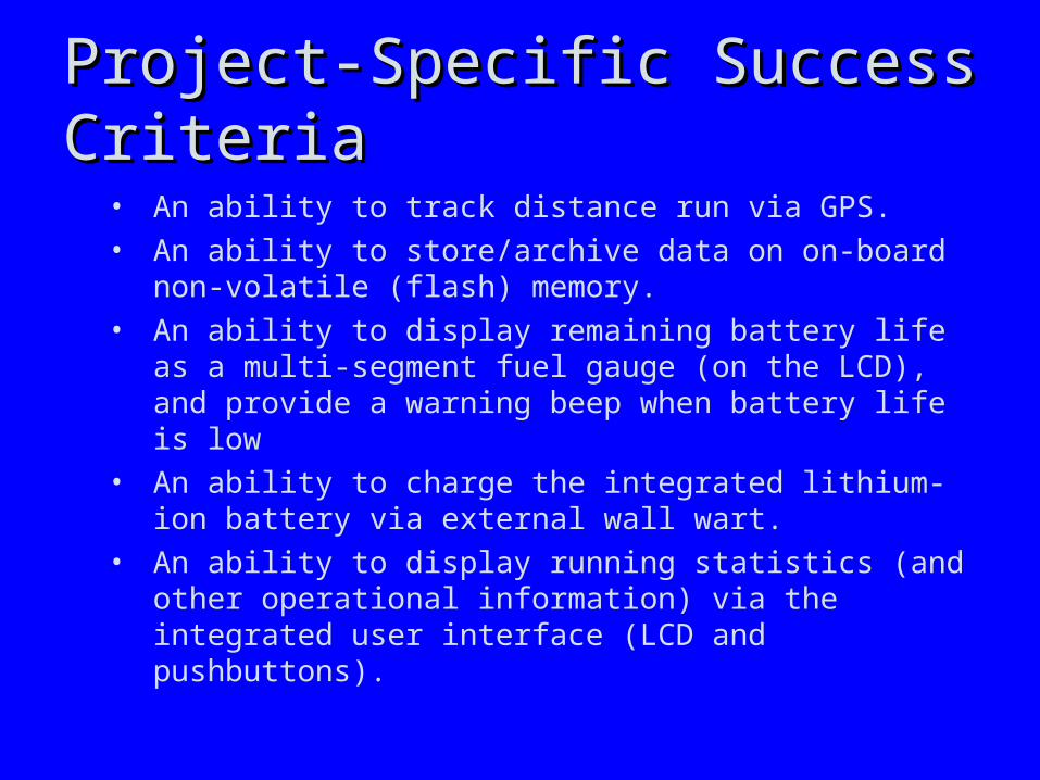
• An ability to track distance run via GPS.• An ability to store/archive data on on-board non-
volatile (flash) memory.• An ability to display remaining battery life as a multi-
segment fuel gauge (on the LCD), and provide a warning beep when battery life is low
• An ability to charge the integrated lithium-ion battery via external wall wart.
• An ability to display running statistics (and other operational information) via the integrated user interface (LCD and pushbuttons).
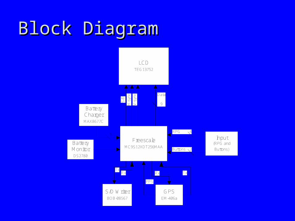
Block DiagramBlock Diagram
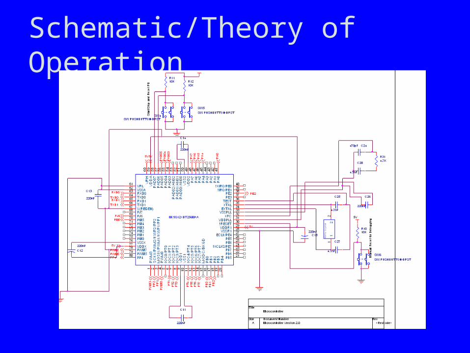
FreescaleMC9S12XDT256MAA
LCDTEG13752
Data
9H-s
ync
V-s
ync
S/D
Input(RPG and
Buttons)
RPG 4
S/D WriterBOB-08567
RxTx
GPSEM-406a
Rx Tx
Buttons 2
Battery ChargerMAX8677C
5
Battery MonitorDS2780
PPS
Component Selection RationaleComponent Selection Rationale
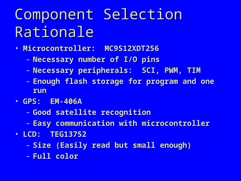
• Microcontroller: MC9S12XDT256Microcontroller: MC9S12XDT256– Necessary number of I/O pinsNecessary number of I/O pins– Necessary peripherals: SCI, PWM, TIMNecessary peripherals: SCI, PWM, TIM– Enough flash storage for program and one runEnough flash storage for program and one run
• GPS: EM-406AGPS: EM-406A– Good satellite recognitionGood satellite recognition– Easy communication with microcontrollerEasy communication with microcontroller
• LCD: TEG13752LCD: TEG13752– Size (Easily read but small enough)Size (Easily read but small enough)– Full colorFull color
Component Selection RationaleComponent Selection Rationale
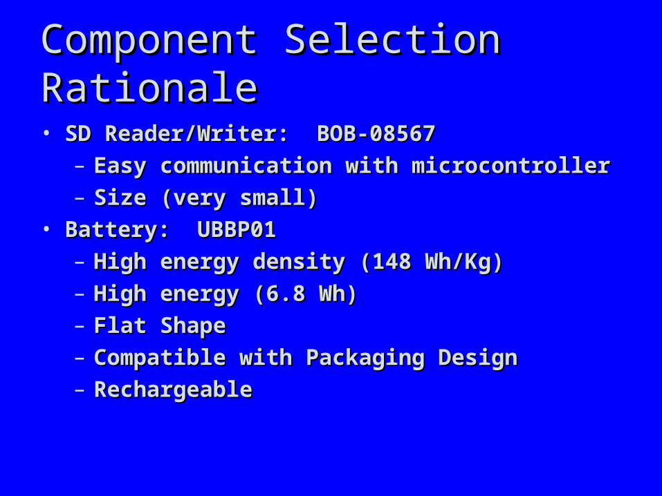
• SD Reader/Writer: BOB-08567SD Reader/Writer: BOB-08567– Easy communication with microcontrollerEasy communication with microcontroller– Size (very small)Size (very small)
• Battery: UBBP01Battery: UBBP01– High energy density (148 Wh/Kg)High energy density (148 Wh/Kg)– High energy (6.8 Wh)High energy (6.8 Wh)– Flat ShapeFlat Shape– Compatible with Packaging DesignCompatible with Packaging Design– RechargeableRechargeable

Component Selection RationaleComponent Selection Rationale• Speaker: 24M5237Speaker: 24M5237
– Size (very small)Size (very small)– Low impedanceLow impedance
• RPG: 61C11-01-08-02RPG: 61C11-01-08-02– Pushbutton for selectingPushbutton for selecting– Free of CostFree of Cost
• Fuel Gauge: DS2780Fuel Gauge: DS2780– Low CostLow Cost– RecommendedRecommended
• Battery Charger: MAX8677CBattery Charger: MAX8677C– Can supply system with power from wall-wart or Can supply system with power from wall-wart or
batterybattery– Compatible with battery voltage and currentCompatible with battery voltage and current
Component Selection RationaleComponent Selection Rationale
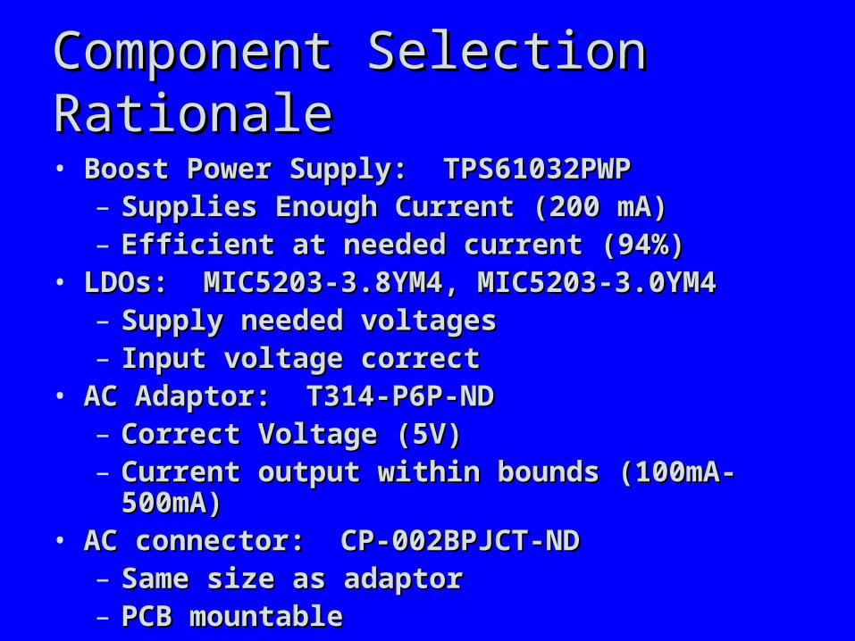
• Boost Power Supply: TPS61032PWPBoost Power Supply: TPS61032PWP– Supplies Enough Current (200 mA)Supplies Enough Current (200 mA)– Efficient at needed current (94%)Efficient at needed current (94%)
• LDOs: MIC5203-3.8YM4, MIC5203-3.0YM4LDOs: MIC5203-3.8YM4, MIC5203-3.0YM4– Supply needed voltagesSupply needed voltages– Input voltage correctInput voltage correct
• AC Adaptor: T314-P6P-NDAC Adaptor: T314-P6P-ND– Correct Voltage (5V)Correct Voltage (5V)– Current output within bounds (100mA-500mA)Current output within bounds (100mA-500mA)
• AC connector: CP-002BPJCT-NDAC connector: CP-002BPJCT-ND– Same size as adaptorSame size as adaptor– PCB mountablePCB mountable
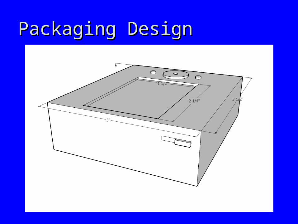
Packaging DesignPackaging Design
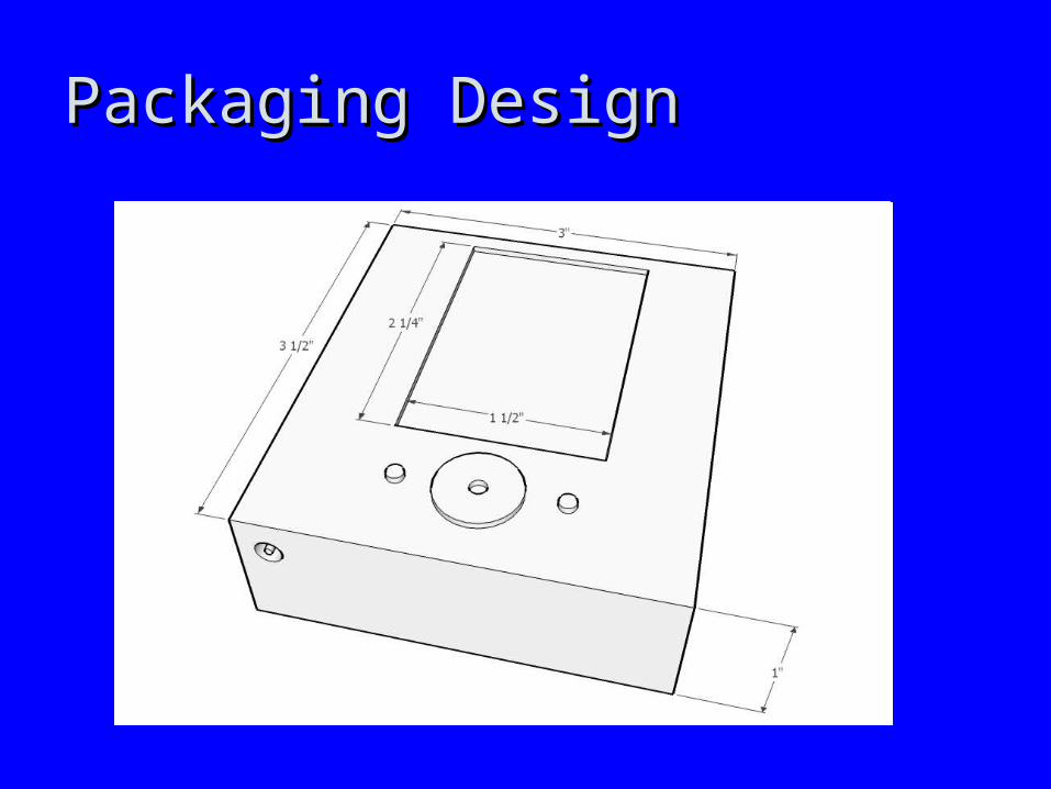
Packaging DesignPackaging Design
Schematic/Theory of Operation
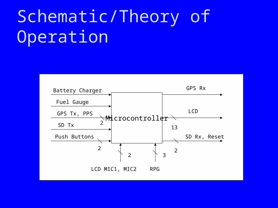
Microcontroller
Battery Charger
Push Buttons
Fuel Gauge
SD Tx
RPGLCD MIC1, MIC2
GPS Tx, PPS
232
SD Rx, Reset
LCD
GPS Rx
132
2
Schematic/Theory of Operation
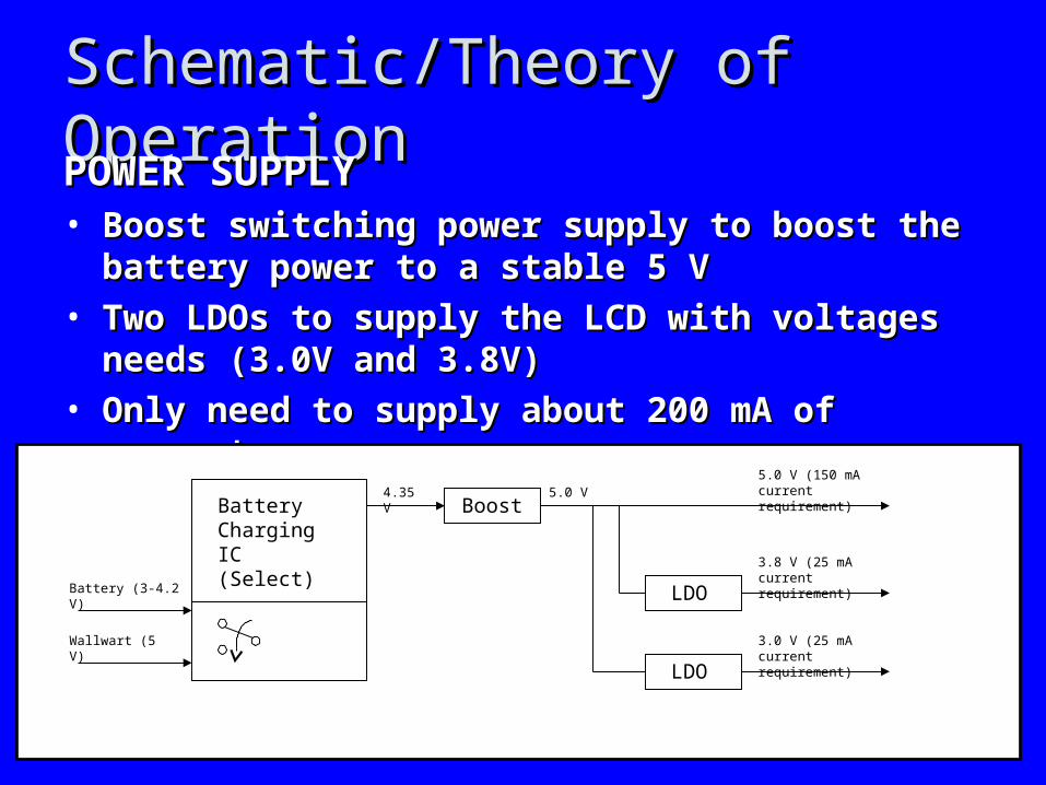
Schematic/Theory of OperationSchematic/Theory of OperationPOWER SUPPLYPOWER SUPPLY• Boost switching power supply to boost the battery Boost switching power supply to boost the battery
power to a stable 5 Vpower to a stable 5 V• Two LDOs to supply the LCD with voltages needs Two LDOs to supply the LCD with voltages needs
(3.0V and 3.8V)(3.0V and 3.8V)• Only need to supply about 200 mA of currentOnly need to supply about 200 mA of current
4.35 VBattery Charging IC (Select)
Battery (3-4.2 V)
Wallwart (5 V)
Boost
LDO
LDO
5.0 V
3.8 V (25 mA current requirement)
3.0 V (25 mA current requirement)
5.0 V (150 mA current requirement)

Schematic/Theory of OperationSchematic/Theory of Operation
Schematic/Theory of OperationSchematic/Theory of Operation
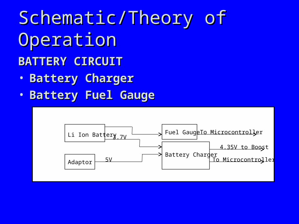
BATTERY CIRCUITBATTERY CIRCUIT• Battery ChargerBattery Charger• Battery Fuel GaugeBattery Fuel Gauge
Li Ion Battery
Battery Charger
Fuel Gauge
Adaptor 5V
3.7V
4.35V to Boost
To Microcontroller
To Microcontroller

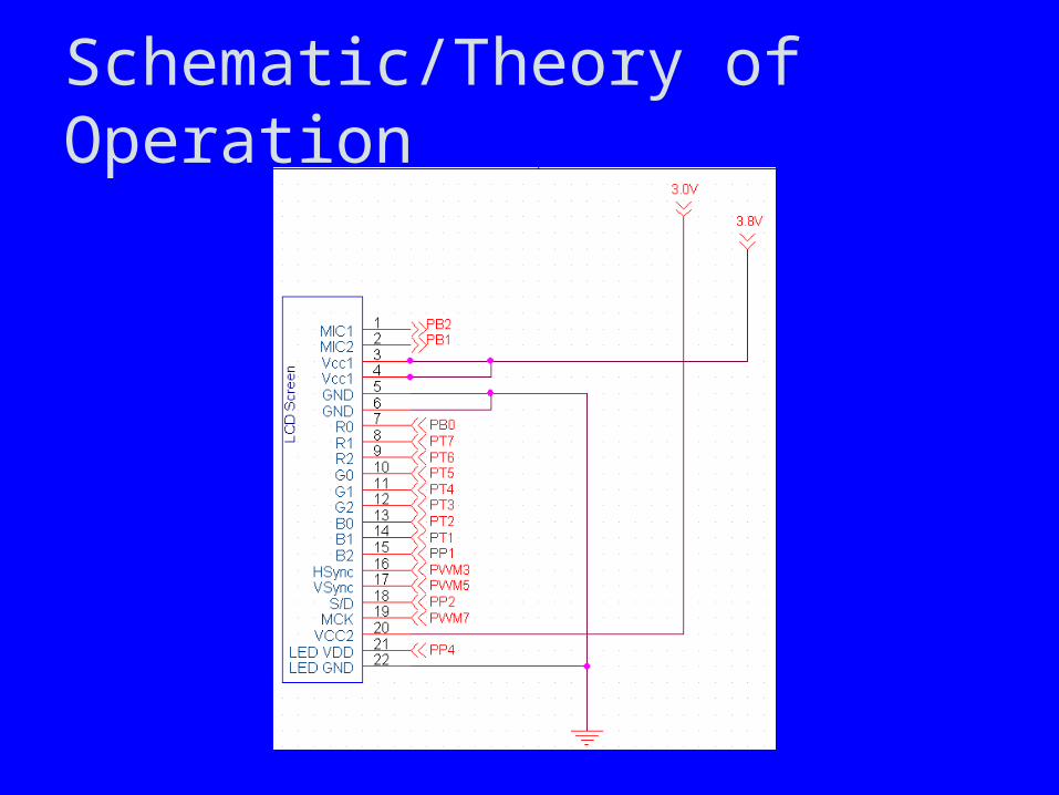
Schematic/Theory of OperationSchematic/Theory of Operation

Schematic/Theory of OperationSchematic/Theory of Operation
LCDTo Microcontroller
9 RGB Data
HSync
VSync
S/D
MCKMIC2
MIC1
From Microcontroller
Schematic/Theory of Operation

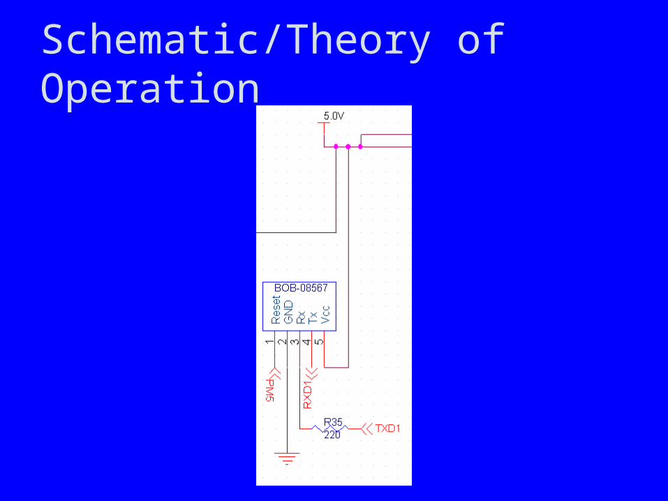
Schematic/Theory of OperationSchematic/Theory of Operation
SDReader/Writer
Rx
Reset
Tx
To MicrocontrollerFrom Microcontroller
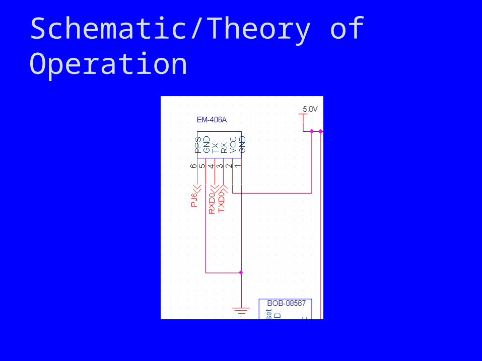
Schematic/Theory of Operation
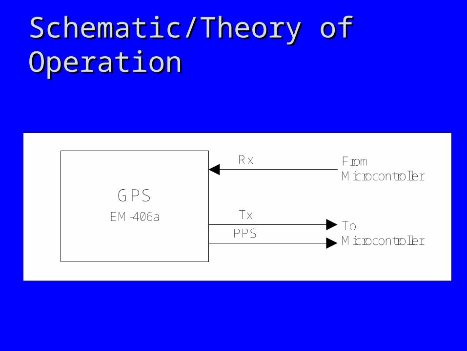
Schematic/Theory of OperationSchematic/Theory of Operation
GPSEM-406a Tx
Rx
PPS
From Microcontroller
To Microcontroller
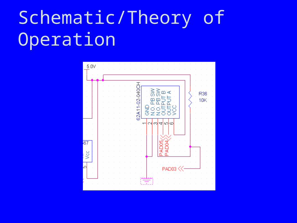
Schematic/Theory of Operation
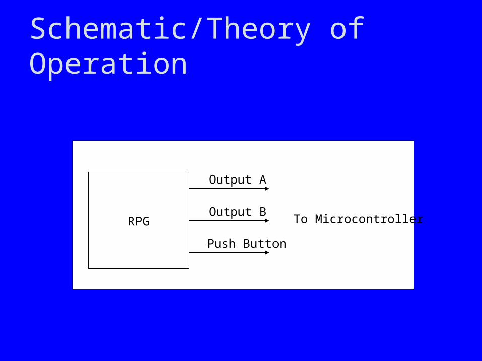
Schematic/Theory of Operation
RPG To Microcontroller
Push Button
Output B
Output A
Schematic/Theory of Operation
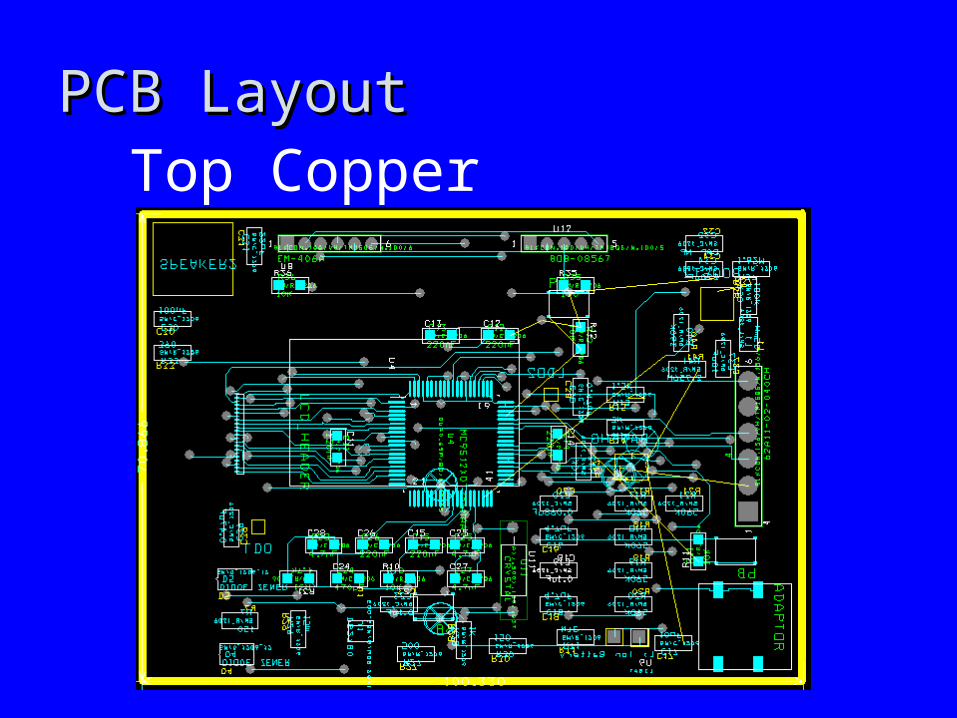
PCB LayoutPCB LayoutTop Copper

PCB LayoutPCB Layout
Bottom Copper/Power
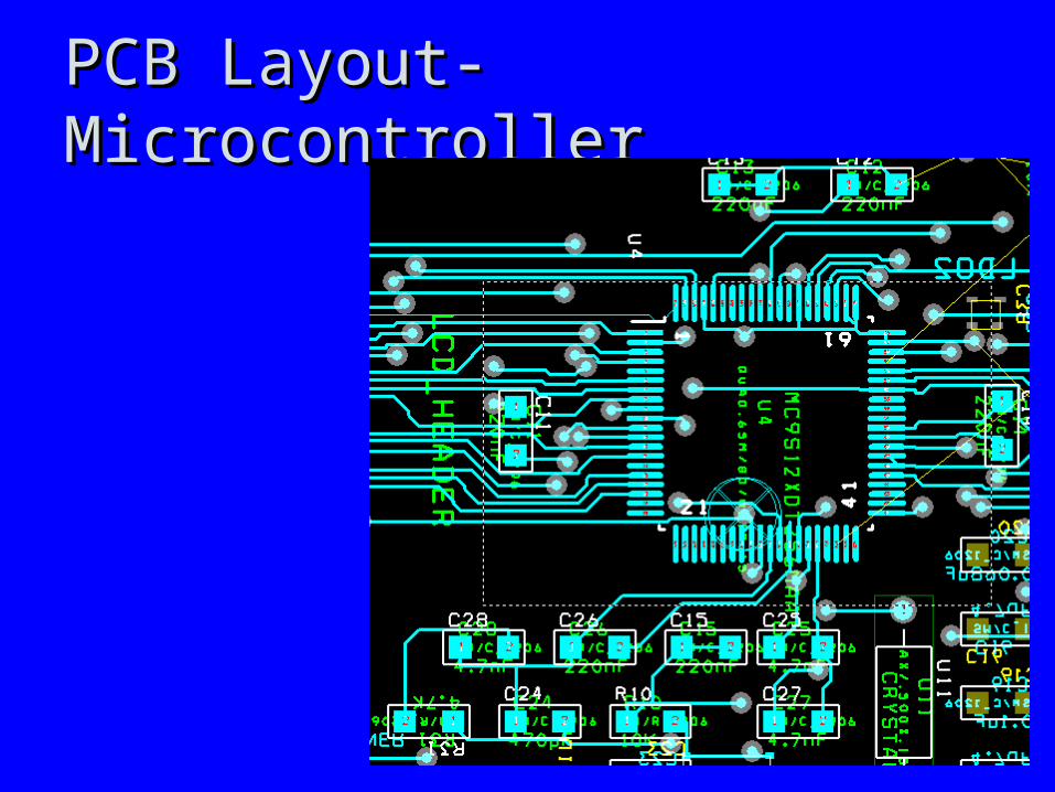
PCB Layout-MicrocontrollerPCB Layout-Microcontroller
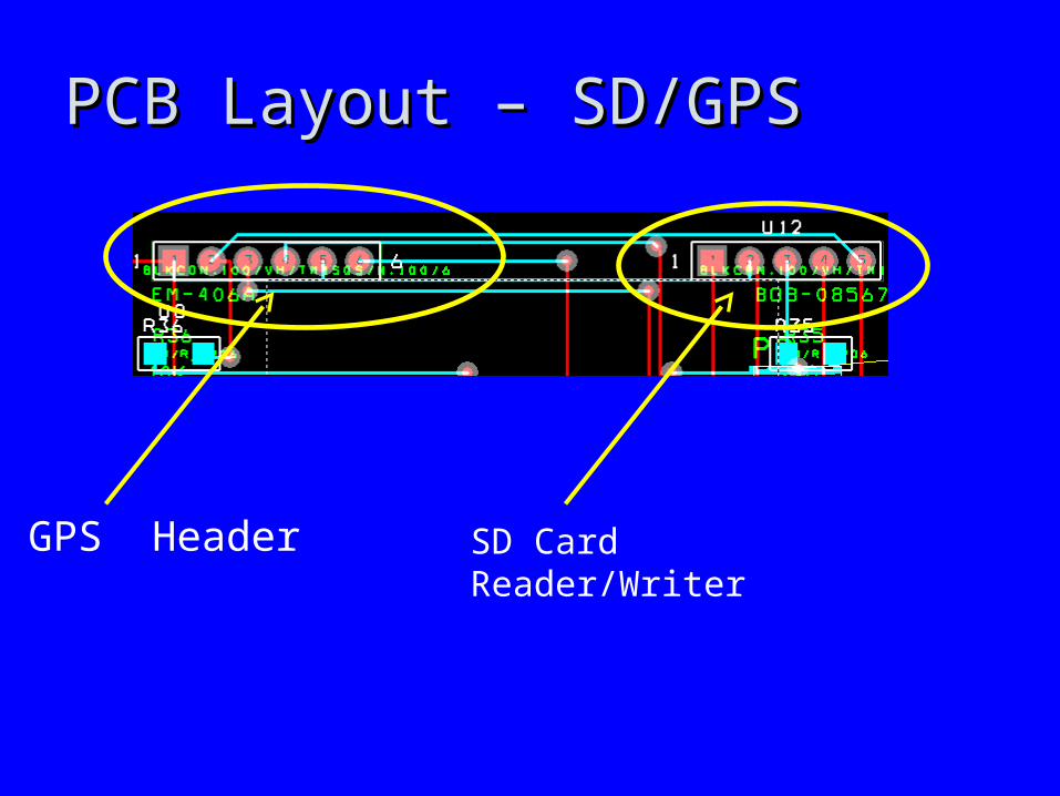
PCB Layout – SD/GPSPCB Layout – SD/GPS
GPS Header SD Card Reader/Writer
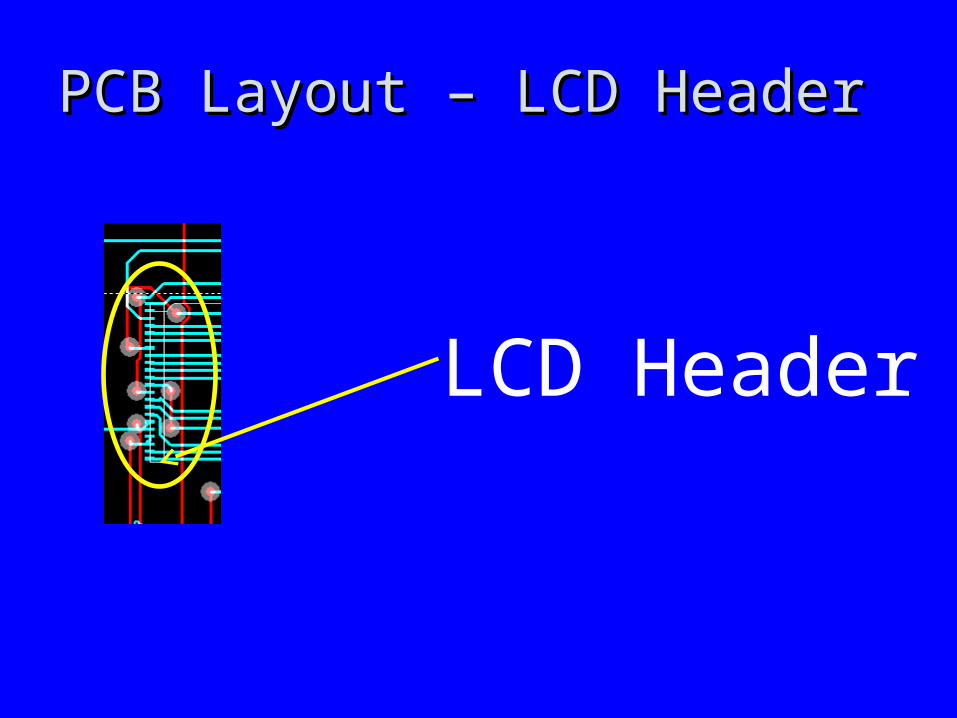
PCB Layout – LCD HeaderPCB Layout – LCD Header
LCD Header

PCB Layout – RPG and PushbuttonsPCB Layout – RPG and Pushbuttons
RPG
Pushbutton
Software Design/Development StatusSoftware Design/Development Status
• Psuedo-code for LCD is underwayPsuedo-code for LCD is underway
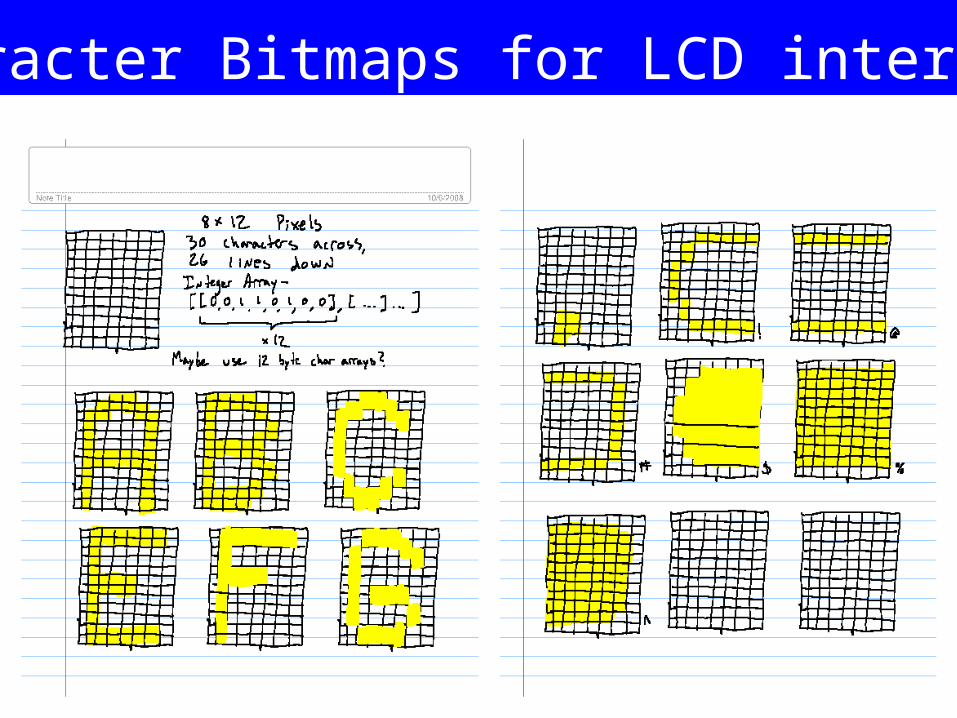
Character Bitmaps for LCD interface
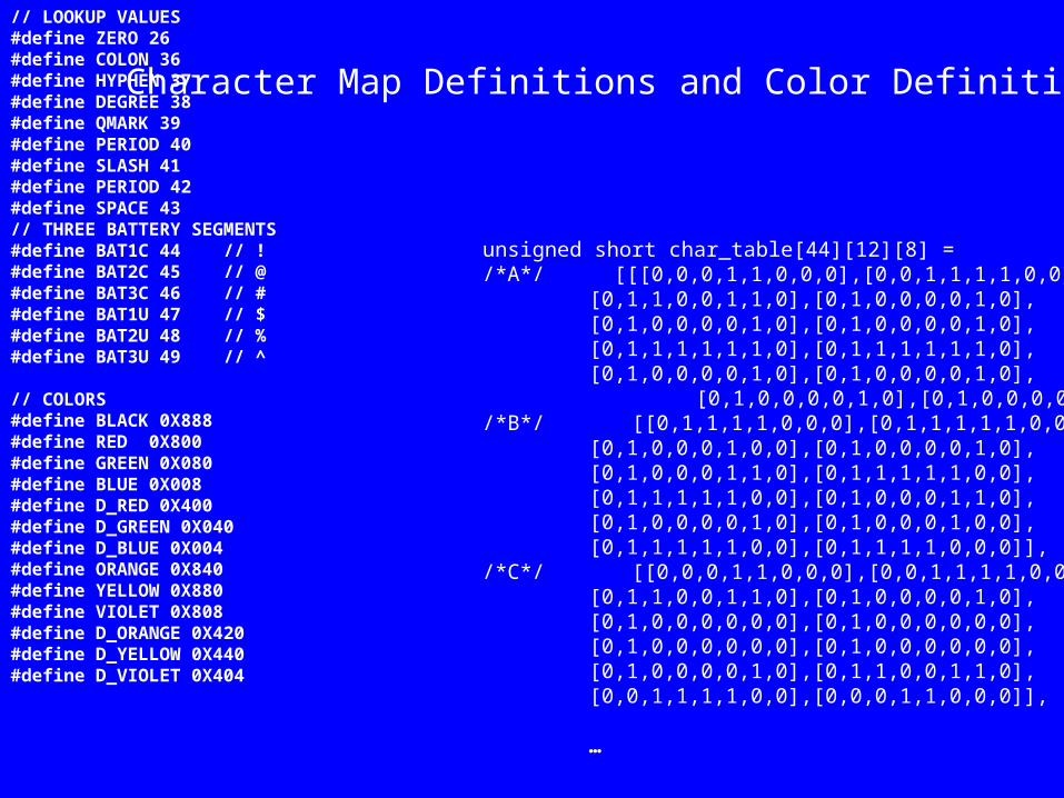
// LOOKUP VALUES #define ZERO 26#define COLON 36#define HYPHEN 37#define DEGREE 38#define QMARK 39#define PERIOD 40#define SLASH 41#define PERIOD 42#define SPACE 43// THREE BATTERY SEGMENTS#define BAT1C 44 // !#define BAT2C 45 // @#define BAT3C 46 // ##define BAT1U 47 // $#define BAT2U 48 // %#define BAT3U 49 // ^
// COLORS#define BLACK 0X888#define RED 0X800#define GREEN 0X080#define BLUE 0X008#define D_RED 0X400#define D_GREEN 0X040#define D_BLUE 0X004#define ORANGE 0X840#define YELLOW 0X880#define VIOLET 0X808#define D_ORANGE 0X420#define D_YELLOW 0X440#define D_VIOLET 0X404
unsigned short char_table[44][12][8] =/*A*/ [[[0,0,0,1,1,0,0,0],[0,0,1,1,1,1,0,0],
[0,1,1,0,0,1,1,0],[0,1,0,0,0,0,1,0],[0,1,0,0,0,0,1,0],[0,1,0,0,0,0,1,0],[0,1,1,1,1,1,1,0],[0,1,1,1,1,1,1,0],[0,1,0,0,0,0,1,0],[0,1,0,0,0,0,1,0],
[0,1,0,0,0,0,1,0],[0,1,0,0,0,0,1,0]],/*B*/ [[0,1,1,1,1,0,0,0],[0,1,1,1,1,1,0,0],
[0,1,0,0,0,1,0,0],[0,1,0,0,0,0,1,0],[0,1,0,0,0,1,1,0],[0,1,1,1,1,1,0,0],[0,1,1,1,1,1,0,0],[0,1,0,0,0,1,1,0],[0,1,0,0,0,0,1,0],[0,1,0,0,0,1,0,0],[0,1,1,1,1,1,0,0],[0,1,1,1,1,0,0,0]],
/*C*/ [[0,0,0,1,1,0,0,0],[0,0,1,1,1,1,0,0],[0,1,1,0,0,1,1,0],[0,1,0,0,0,0,1,0],[0,1,0,0,0,0,0,0],[0,1,0,0,0,0,0,0],[0,1,0,0,0,0,0,0],[0,1,0,0,0,0,0,0],[0,1,0,0,0,0,1,0],[0,1,1,0,0,1,1,0],[0,0,1,1,1,1,0,0],[0,0,0,1,1,0,0,0]],
…
Character Map Definitions and Color Definitions

for (i=0; i<12;i++){vcurr = vsync;for (j=0;j<30;j++){
hcurr = hsync;pixelout(char_table[lookup[j]][i][0]);while (hsync==hcurr){}hcurr = hsync;pixelout(char_table[lookup[j]][i][1]);while (hsync==hcurr){}hcurr = hsync;pixelout(char_table[lookup[j]][i][2]);while (hsync==hcurr){}hcurr = hsync;pixelout(char_table[lookup[j]][i][3]);while (hsync==hcurr){}hcurr = hsync;pixelout(char_table[lookup[j]][i][4]);while (hsync==hcurr){}hcurr = hsync;pixelout(char_table[lookup[j]][i][5]);while (hsync==hcurr){}hcurr = hsync;pixelout(char_table[lookup[j]][i][6]);while (hsync==hcurr){}hcurr = hsync;pixelout(char_table[lookup[j]][i][7]);while (hsync==hcurr){}
}while (vsync==vcurr){}
}
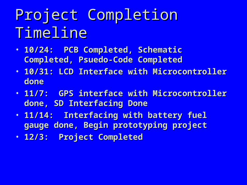
Project Completion TimelineProject Completion Timeline
• 10/24: PCB Completed, Schematic Completed, 10/24: PCB Completed, Schematic Completed, Psuedo-Code CompletedPsuedo-Code Completed
• 10/31: LCD Interface with Microcontroller done10/31: LCD Interface with Microcontroller done• 11/7: GPS interface with Microcontroller done, SD 11/7: GPS interface with Microcontroller done, SD
Interfacing DoneInterfacing Done• 11/14: Interfacing with battery fuel gauge done, 11/14: Interfacing with battery fuel gauge done,
Begin prototyping projectBegin prototyping project• 12/3: Project Completed12/3: Project Completed

Questions & DiscussionQuestions & Discussion


