ECE 546 – Jose Schutt-Aine 1 ECE 546 Lecture - 07 Nonideal Conductors and Dielectrics Spring 2014 Jose E. Schutt-Aine Electrical & Computer Engineering University of Illinois [email protected]
Transcript
ECE 546 – Jose Schutt-Aine 1
ECE 546Lecture - 07
Nonideal Conductors and Dielectrics
Spring 2014
Jose E. Schutt-AineElectrical & Computer Engineering
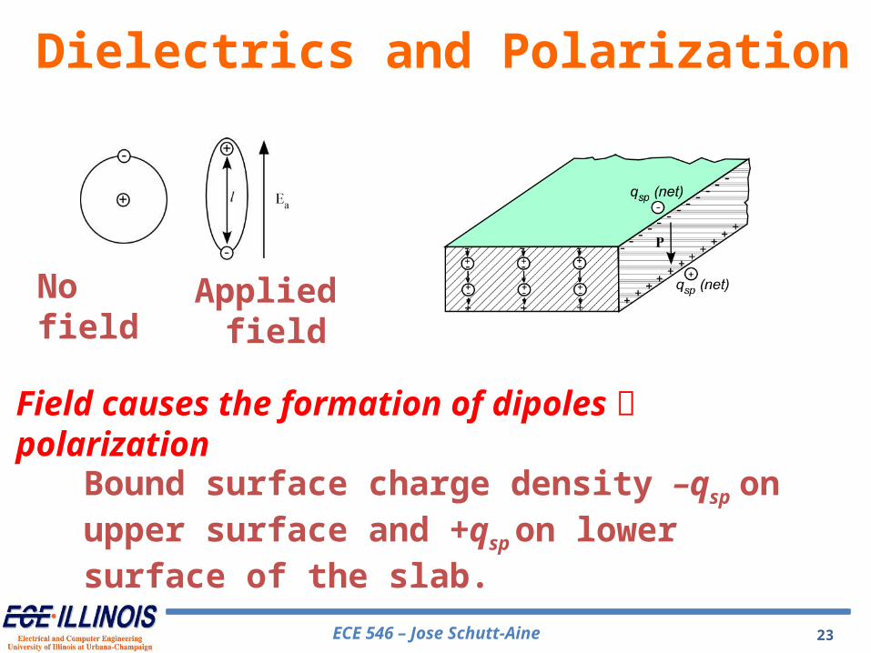
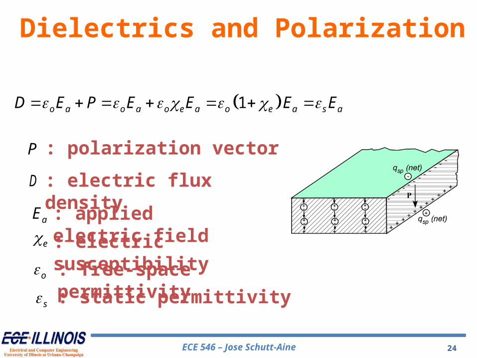
When a material is subjected to an applied electric field, the centroids of the positive and negative charges are displaced relative to each other forming a linear dipole.
When the applied fields begin to alternate in polarity, the permittivities are affected and become functions of the frequency of the alternating fields.
AC Variations
ECE 546 – Jose Schutt-Aine 28
Reverses in polarity cause incremental changes in the static conductivity ssheating of materials using microwaves (e.g. food cooking)
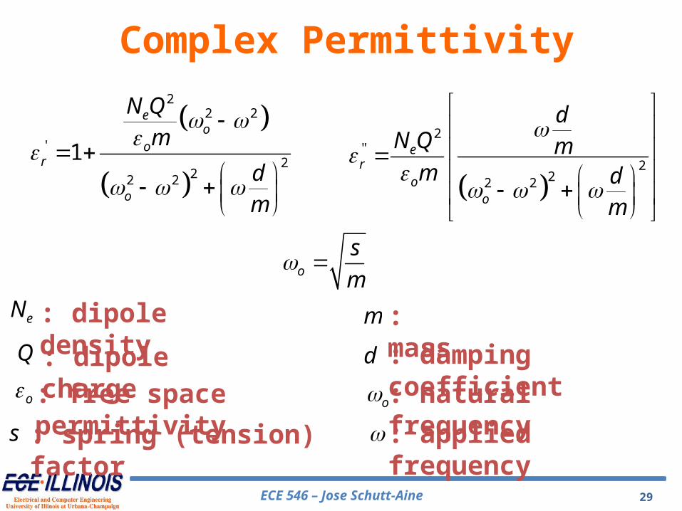
When an electric field is applied, it is assumed that the positive charge remains stationary and the negative charge moves relative to the positive along a platform that exhibits a friction (damping) coefficient d.
AC Variations
ECE 546 – Jose Schutt-Aine 29
22 2
'2
22 2
1
eo
or
o
N Q
m
dm
2"
222 2
er
oo
dN Q m
m dm
Complex Permittivity
eN
o
Q
o
m
d : damping coefficient
: mass
: free space permittivity
: dipole charge
: dipole density
: natural frequency: applied frequency
o
s
m
s : spring (tension) factor
ECE 546 – Jose Schutt-Aine 30
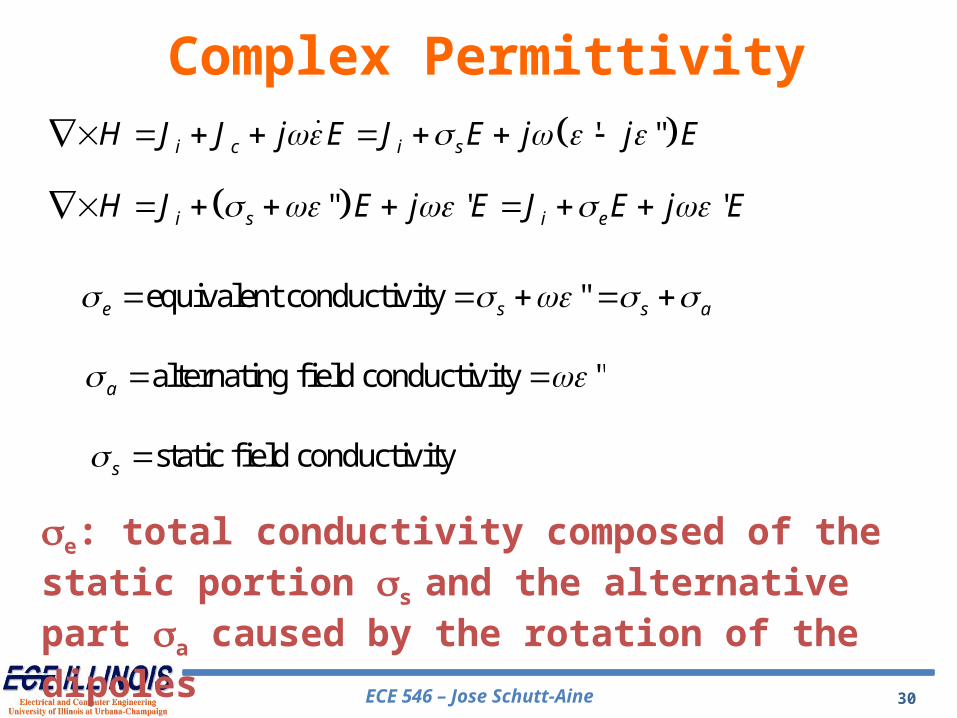
' "i c i sH J J j E J E j j E
Complex Permittivity
" ' 'i s i eH J E j E J E j E
equivalent conductivity "e s s a
alternating field conductivity "a
static field conductivitys
se: total conductivity composed of the static portion ss and the alternative part sa caused by the rotation of the dipoles
ECE 546 – Jose Schutt-Aine 31
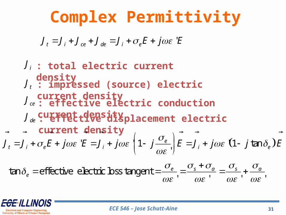
't i ce de i eJ J J J J E j E Complex Permittivity
iJ
tJ
ceJ
deJ
: total electric current density: impressed (source) electric current density: effective electric conduction current density: effective displacement electric current density
' ' 1 ' 1 tan'
et i e i i eJ J E j E J j j E J j j E
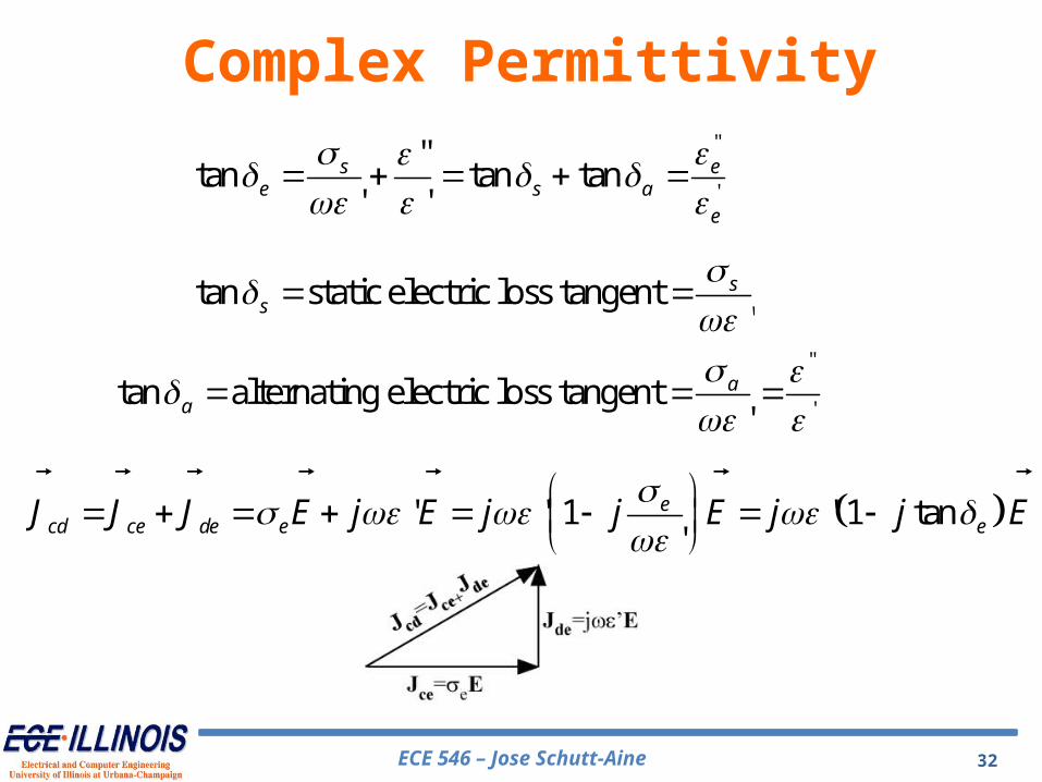
tan effective electric loss tangent' ' ' '
e s a s ae
ECE 546 – Jose Schutt-Aine 32
Complex Permittivity"
'
"tan tan tan
' 's e
e s ae
tan static electric loss tangent'
ss
"
'tan alternating electric loss tangent
'a
a
' ' 1 ' 1 tan'
ecd ce de e eJ J J E j E j j E j j E
ECE 546 – Jose Schutt-Aine 33
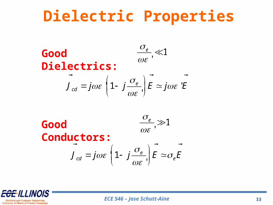
Dielectric Properties
' 1 ''
ecdJ j j E j E
1'
e
' 1'
ecd eJ j j E E
1'
e
Good Dielectrics:
Good Conductors:
ECE 546 – Jose Schutt-Aine 34
Dielectric Properties
' 1 ''
ecdJ j j E j E
1'
e
' 1'
ecd eJ j j E E
1'
e
Good Dielectrics:
Good Conductors:
ECE 546 – Jose Schutt-Aine 35
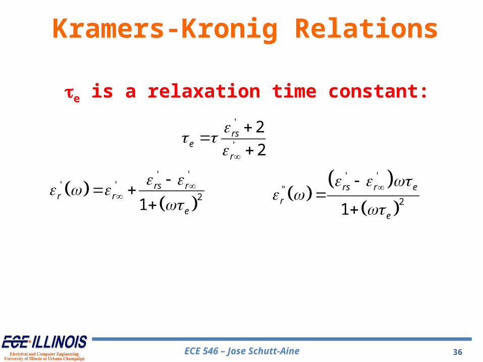
Kramers-Kronig Relations
"'
2 20
' '21 '
'
rr d
There is a relation between the real and imaginary parts of the complex permittivity:
Debye Equation
'"
2 20
1 '2'
'
rr d
' '' " '( ) ( ) ( )
1rs r
r r r re
jj
ECE 546 – Jose Schutt-Aine 36
Kramers-Kronig Relations
'
'
2
2rs
er
te is a relaxation time constant:
' '' '
21
rs rr r
e
' '
"2
1
rs r e
r
e
ECE 546 – Jose Schutt-Aine 37
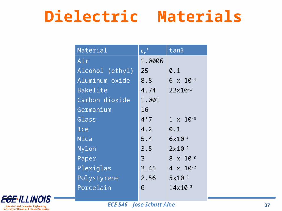
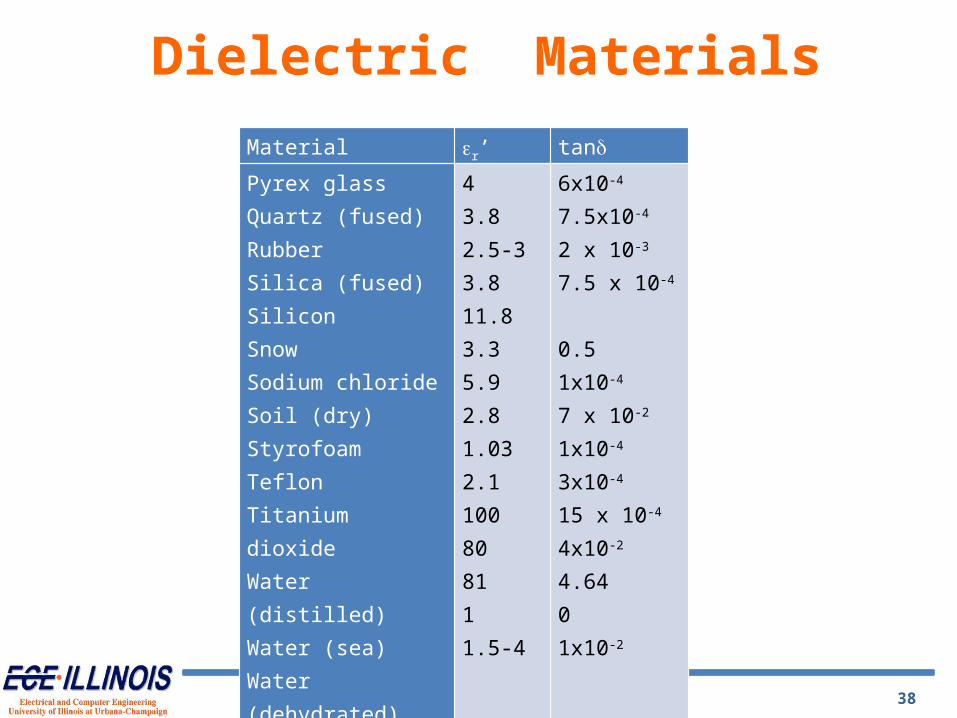
Material er’ tandAirAlcohol (ethyl)Aluminum oxideBakeliteCarbon dioxideGermaniumGlassIceMicaNylonPaperPlexiglasPolystyrenePorcelain
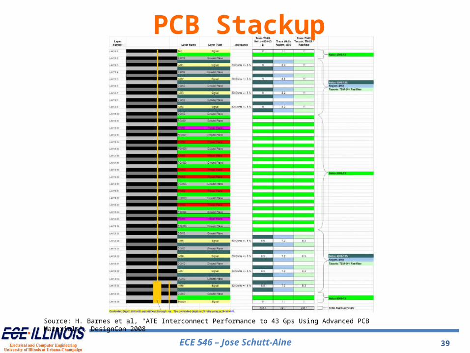
Source: H. Barnes et al, "ATE Interconnect Performance to 43 Gps Using Advanced PCB Materials", DesignCon 2008
PCB Stackup
ECE 546 – Jose Schutt-Aine 40
The skew (time delay) between the two traces of the differential pair should be zero. Any skew between the two traces causes the differential signal to convert into a common signal.
Differential signaling is widely used in the industry today. High-speed serial interfaces such as PCI-E, XAUI, OC768, and CEI use differential signaling for transmitting and receiving data in point-to-point topology between a driver (TX) and receiver (RX) connected by a differential pair.
Differential Signaling
ECE 546 – Jose Schutt-Aine 41
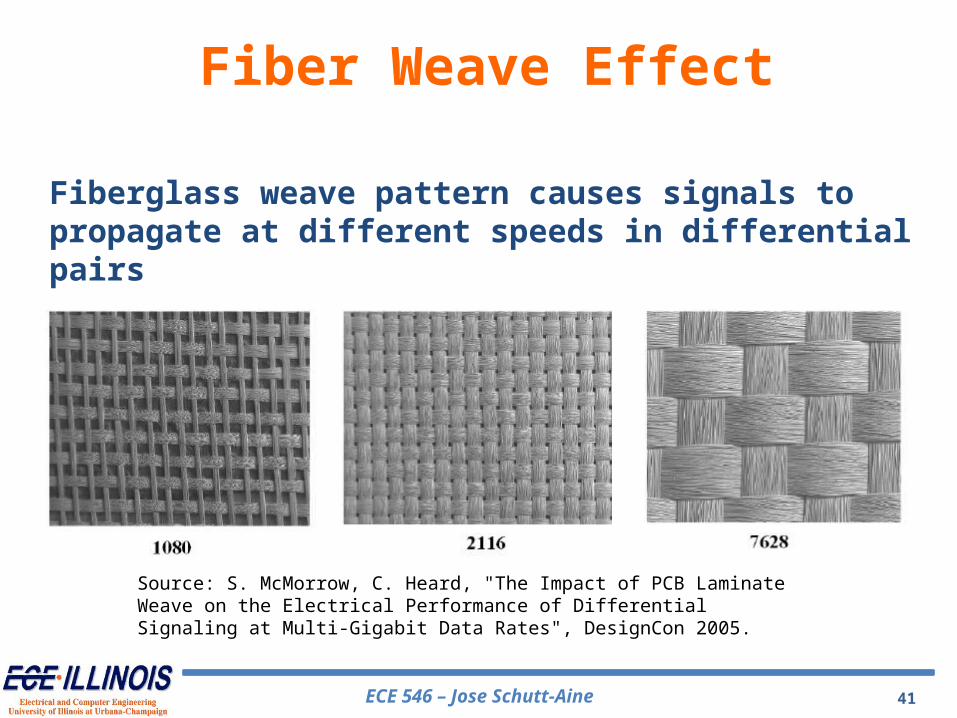
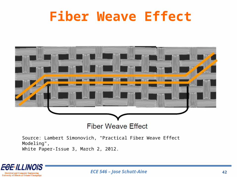
Fiber Weave Effect
Source: S. McMorrow, C. Heard, "The Impact of PCB Laminate Weave on the Electrical Performance of Differential Signaling at Multi-Gigabit Data Rates", DesignCon 2005.
Fiberglass weave pattern causes signals to propagate at different speeds in differential pairs
Source: S. Hall and H. Heck , Advanced Signal Integrity for High-Speed Digital Designs, J. Wiley, IEEE , 2009.
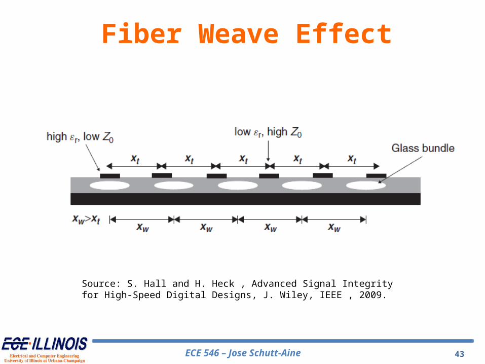
Fiber Weave Effect
ECE 546 – Jose Schutt-Aine 44
Source: S. McMorrow, C. Heard, "The Impact of PCB Laminate Weave on the Electrical Performance of Differential Signaling at Multi-Gigabit Data Rates", DesignCon 2005.
Fiber Weave EffectGroup delay variation
ECE 546 – Jose Schutt-Aine 45
Source: S. McMorrow, C. Heard, "The Impact of PCB Laminate Weave on the Electrical Performance of Differential Signaling at Multi-Gigabit Data Rates", DesignCon 2005.
Fiber Weave EffectGroup delay variation: effect of angle
ECE 546 – Jose Schutt-Aine 46
Source: S. Hall and H. Heck , Advanced Signal Integrity for High-Speed Digital Designs, J. Wiley, IEEE , 2009.
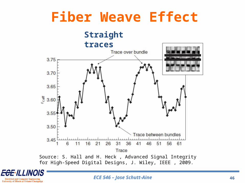
Fiber Weave EffectStraight traces
ECE 546 – Jose Schutt-Aine 47
Source: S. Hall and H. Heck , Advanced Signal Integrity for High-Speed Digital Designs, J. Wiley, IEEE , 2009.
Fiber Weave Effect
45o traces
ECE 546 – Jose Schutt-Aine 48
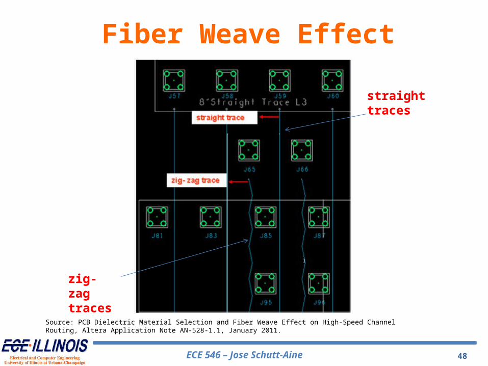
Source: PCB Dielectric Material Selection and Fiber Weave Effect on High-Speed Channel Routing, Altera Application Note AN-528-1.1, January 2011.
Fiber Weave Effect
straight traces
zig-zag traces
ECE 546 – Jose Schutt-Aine 49
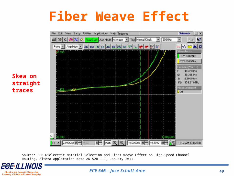
Source: PCB Dielectric Material Selection and Fiber Weave Effect on High-Speed Channel Routing, Altera Application Note AN-528-1.1, January 2011.
Fiber Weave Effect
Skew on straight traces
ECE 546 – Jose Schutt-Aine 50
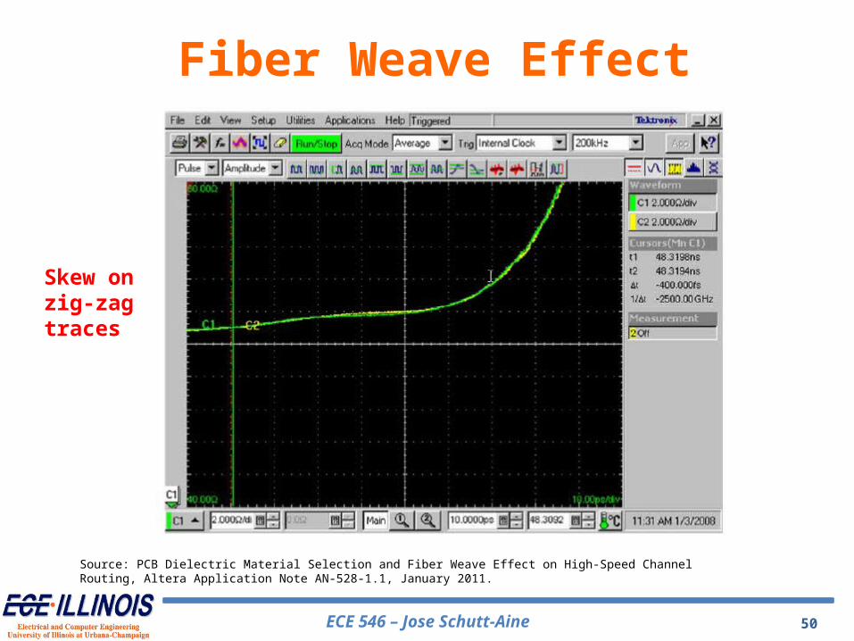
Source: PCB Dielectric Material Selection and Fiber Weave Effect on High-Speed Channel Routing, Altera Application Note AN-528-1.1, January 2011.
Fiber Weave Effect
Skew on zig-zag traces
ECE 546 – Jose Schutt-Aine 51
• Mitigation TechniquesUse wider widths to achieve impedance targets. Specify a denser weave (2116, 2113, 7268, 1652)
compared to a sparse weave (106, 1080). Move to a better substrate such as Nelco 4000-13 Perform floor planning such that routing is at an angle
rather than orthogonal. Make use of zig-zag routing