101
1 ECE2262 Electric Circuits Chapter 2: Resistive Circuits ! ENG 1450

1
ECE2262 Electric Circuits
Chapter 2: Resistive Circuits ! ENG 1450

2

3
2.1 Ohm’s Law
R1

4
The voltage across a resistance is directly proportional to the current flowing through it.
v = Ri
R = vi
- 1 ! (ohm) =1V1A
Conductance: G = 1R
- 1 S (siemens) =1A1V

5
The power absorbed by a resistor
p = vi = Ri2
= v2
R

6
R = vi
!
R = 0 ! “Short” Circuit ! v = 0
R = ! ! “Open” Circuit ! i = 0
7
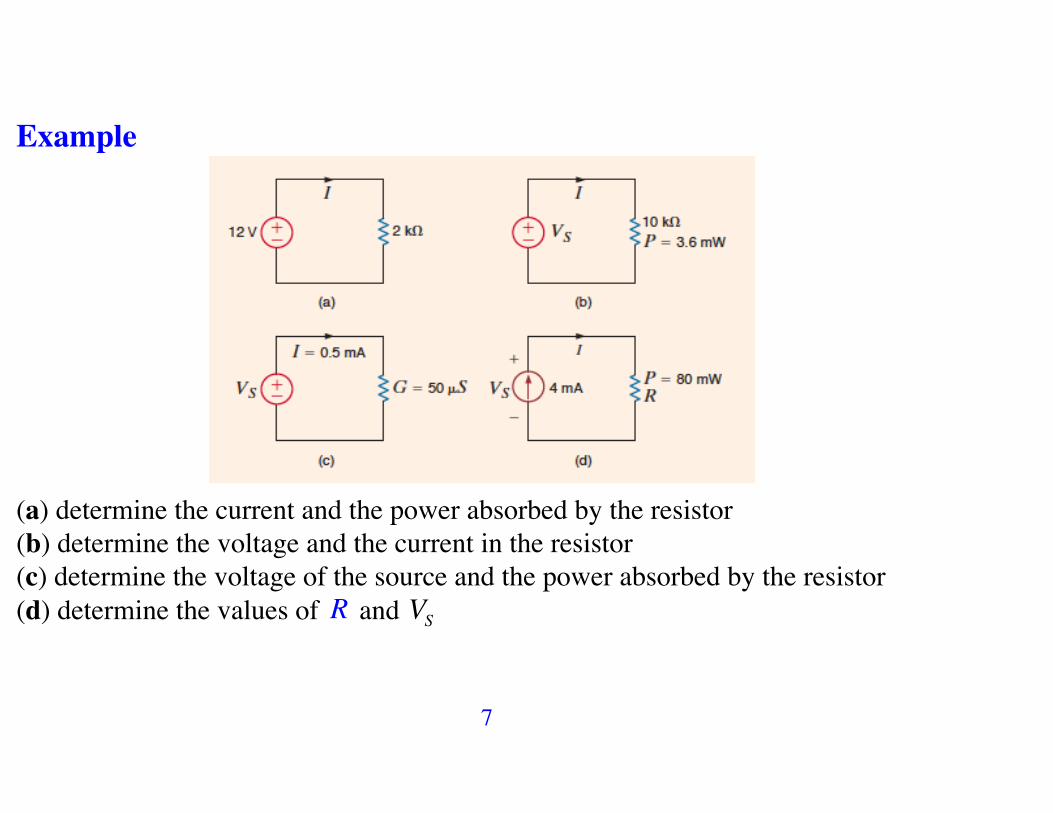
Example
(a) determine the current and the power absorbed by the resistor (b) determine the voltage and the current in the resistor(c) determine the voltage of the source and the power absorbed by the resistor(d) determine the values of R and VS

8
! (d)
I = 4 !10"3A , P = 80 !10"3W
P = RI 2 ! R = PI 2
! R = 5 !103" = 5k!
VS = RI ! VS = 20V
9
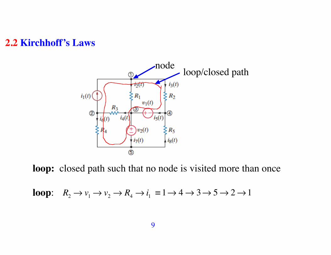
2.2 Kirchhoff’s Laws
nodeloop/closed path
loop: closed path such that no node is visited more than once
loop: R2 ! v1! v2 ! R4 ! i1 ! 1" 4" 3" 5" 2"1

10
Kirchhoff’s Current Law - KCL
The algebraic sum of all currents entering any node is zero ! KCL is based on the principle of the conservation of charge !
Convention*: In writing KCL we consider the current that enters a node with a positive sign and the current that leaves a node with negative sign.
i1 > 0
i2 < 0
i3 > 0 i1 ! i2 + i3 = 0
Convention**: !i1 + i2 ! i3 = 0

11
iin! = iout!
The sum of all the currents flowing into a node equals the sum of all the currents flowing out
In applying this rule we just need to pay attention to the arrows indicating the flow directions of the element currents present at each node

12
Example
• Node 1: !i2 ! i1 + i5 = 0 ; • Node 2: i2 ! i3 + 50i2 = 0
• Node 3: i1 ! i4 ! 50i2 = 0 ; • Node 4: i3 + i4 ! i5 = 0

13
In writing these equations, a positive sign is used for a current leaving a node

14
SUPERNODE: we can make supernodes by aggregating nodes
node 2 : !i1 ! i6 + i4 = 0 node 3 : i2 ! i4 + i5 ! i7 = 0
Adding 2 and 3 : !i1 ! i6 + i2 + i5 ! i7 = 0 ! Supernode 2&3

15
Example: Write all KCL equations

16

17
Kirchhoff’s Voltage Law - KVL
The algebraic sum of all voltages in every loop of the circuit is zero ! KVL is based on the principle of the conservation of energy !
Convention: In writing KVL when we cross a component from positive to negative terminal we consider its voltage with a positive sign. When we cross a component from negative to positive terminal we consider its voltage with a negative sign.
+ !V > 0
+! V < 0

18
vdrop! = vrise!
The sum of all voltage rises encountered around any closed loop of elements in a circuit equals the sum of all voltage drops encountered around the same loop voltage rise ! loop moves from ! to + voltage drop ! loop moves from + to !
19
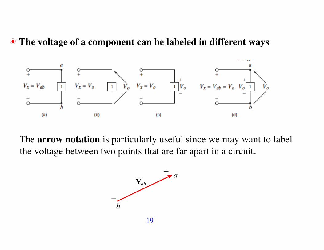
The voltage of a component can be labeled in different ways
The arrow notation is particularly useful since we may want to label the voltage between two points that are far apart in a circuit.
a
b
+
!
Vab

20
Example

21
Example Find Vad , Veb
• loop a!b!c!d!a: 24 ! 4 + 6 !Vad = 0 ! Vad = 26V
• loop a!b!e! f!a: 24 !Veb ! 8 ! 6 = 0 ! Veb = 10V

22
Example R1 , R2 , RC , RE , VCC , V0 , ! - known; (a) find the equations needed to determine the current in each element of this circuit; 6 unknown currents (b) Devise a formula for computing iB

23
• KCL for nodes a, b, c, d
1. Node a: !i1 ! iC + iCC = 0 ; 2. Node b: !iB ! i2 + i1 = 0
3. Node c: !iE + iB + iC = 0 ; • Node d: xxxxxx

24
• Dependent current source: 4. iC = !iB

25
• KVL loop b!c!d!b: 5. V0 + iERE ! i2R2 = 0
loop b!a!d!b: 6. !i1R1 +VCC ! i2R2 = 0
These six equations allow to determine the current in each element of the circuit and obtain
iB =VCCR2 / R1 + R2( )!V0
R1R2 / R1 + R2( ) + 1+ "( )RE

26
Example Find Vx
b!
6 ! 24 + I " (2 "103) + I " (5 "103) + I " (2"103 ) = 0
I
9 "103( ) " I =18
I = 2mA
Vx = 5 "103( )" I = 10V
KVL
27
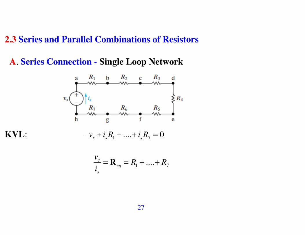
2.3 Series and Parallel Combinations of Resistors
A. Series Connection - Single Loop Network
KVL: !vs + isR1 + ....+ isR7 = 0
vsis= Req = R1 + ....+ R7

28
Equivalent Circuit
Req = Rii!
Note: Req ! Ri

29
Multiple-Source/Resistor Networks
By KVL: R1i + R2i ! v1 + v2 ! v3 + v4 + v5 = 0 ! R1 + R2( )i = v
v = v1 + v3 ! v2 ! v4 ! v5

30
B. Parallel Connection - Single Node Network
KCL: is = i1 + ...+ i4
The voltage across each resistor is the same: i j =vsRj
is =vsR1
+ ...+ vsR4
! isvs
= 1R1
+ ...+ 1R4
Req =1
1R1
+ ...+ 1R4
31
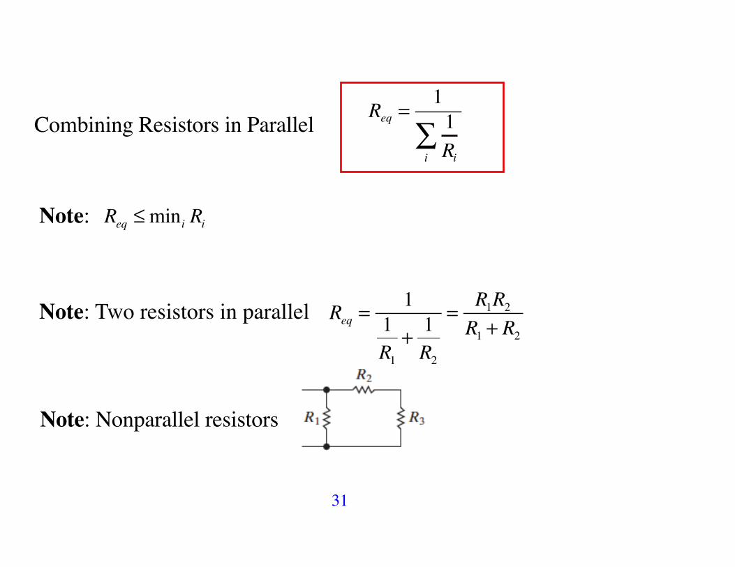
Req =1
1Rii
! Combining Resistors in Parallel
Note: Req !mini Ri
Note: Two resistors in parallel Req =1
1R1
+ 1R2
= R1R2R1 + R2
Note: Nonparallel resistors

32
Multiple-Source/Resistor Networks
By KCL: i1 ! i2 ! i3 + i4 ! i5 ! i6 = 0 ! i1 ! i3 + i4 ! i6sources
! "## $## = i2 + i5
i0 = i1 ! i3 + i4 ! i6

33
Example Find is ,i1,i2
• Equivalent circuit
Req =18 ! 6 + 3( )18 + 6 + 3( ) = 6"
is =1204 + 6
= 12A! vxy = 12 " 6 = 72V ! i1 =vxy18
= 4A , i2 =vxy9
= 8A

34
Example (E2.14)
RAB = 22k!

35
Example Find v and the power delivered to the circuit by the current source.
P5A = 300W - delivered

36
Example (Mathematical Inequality)
a b
ab
A B
•Switch open ! RAB =a + b2
• Switch closed (short circuit) ! RAB =aba + b
+ aba + b
= 2aba + b
is smaller than before
2aba + b
! a + b2
2aba + b
= 121a+ 1b
!"#
$%&
'()
*+,
-1
! The arithmetic mean is greater than the harmonic mean

37
C. ! ! Y Equivalent Circuits
R2
R1 R3
Ra Rb
Rc
! Y
• Terminal c, a: Rca= R1 || R2 + R3( ) Rca = Ra + Rc

38
• Terminal b, c: Rbc= R3 || R1 + R2( ) Rbc = Rb + Rc
R2
R1 R3
Ra Rb
Rc
! Y
a
c
b b
c
aR3 R1
R2 Rb Ra
Rc
• Terminal a, b: Rab= R2 || R1 + R3( ) Rab = Ra + Rb

39
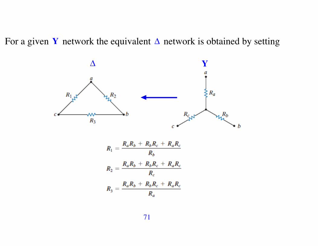
For a given ! network the equivalent Y network is obtained by setting
R2 R1 + R3( )R1 + R2 + R3
= Ra + Rb
R3 R1 + R2( )R1 + R2 + R3
= Rb + Rc
R1 R2 + R3( )R1 + R2 + R3
= Ra + Rc

40
Ra =R1R2
R1 + R2 + R3 ; Rb =
R2R3R1 + R2 + R3
; Rc =R1R3
R1 + R2 + R3
Note: R1 = R2 = R3 = R ! Ra ,Rb ,Rc = ?

41
Example Find the current and power supplied by the 40 V source.
We wish to replace the upper ! network by the equivalent Y network

42
Rc
Ra
Rb
Ra = 100 !125100 +125 + 25
= 50"
Rb = 125 ! 25100 +125 + 25
= 12.5"
Rc = 100 ! 25100 +125 + 25
= 10"

43
The equivalent circuits
Req = 55 +
10 + 40( )! 12.5 + 37.5( )10 + 40( ) + 12.5 + 37.5( ) = 55 + 50 ! 50
100 = 80!
! i40V = 4080
= 0.5A P40V = 40 ! 0.5 = 20W - supplied
44
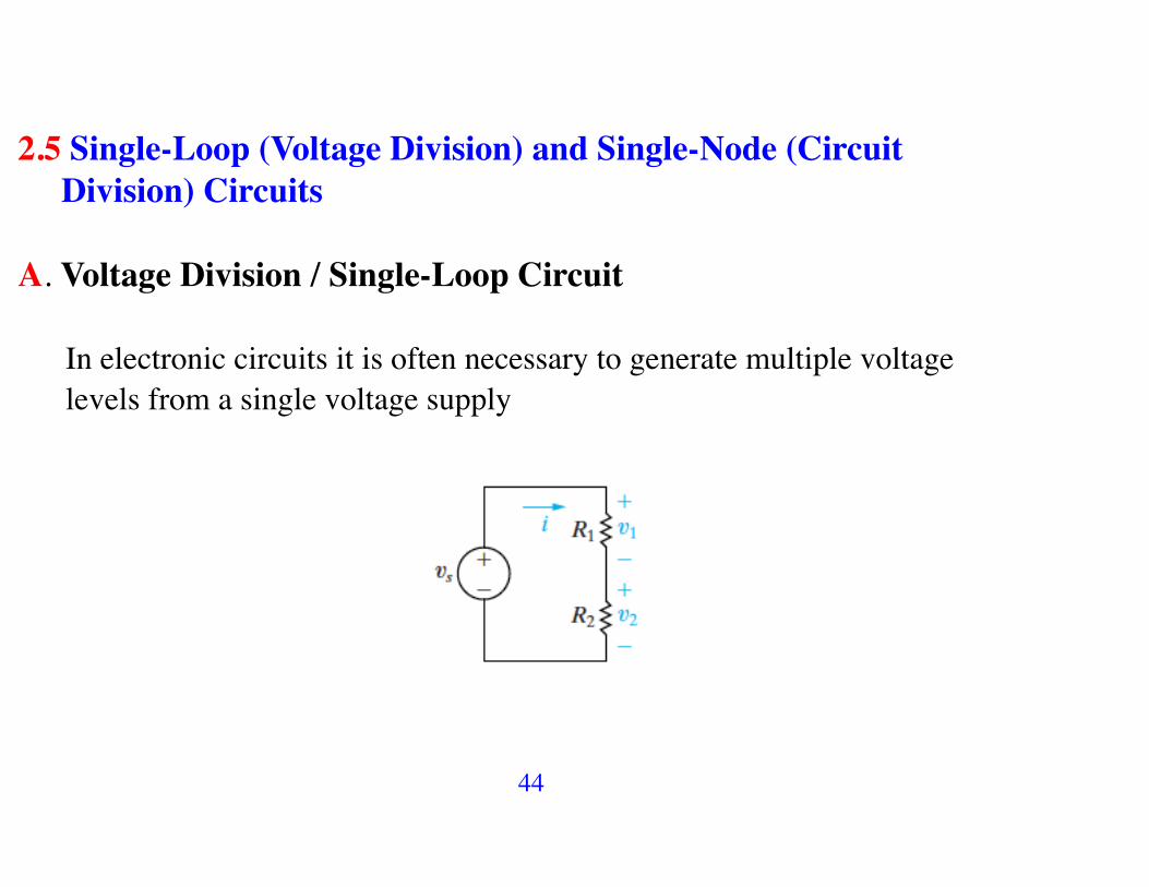
2.5 Single-Loop (Voltage Division) and Single-Node (Circuit Division) Circuits
A. Voltage Division / Single-Loop Circuit
In electronic circuits it is often necessary to generate multiple voltage levels from a single voltage supply

45
KVL + Ohm’s L vs = iR1 + iR2 ! i = vs
R1 + R2
v1 = iR1 , v2 = iR2
v1 =R1
R1 + R2vs , v2 =
R2R1 + R2
vs

46
v2 =R2
R1 + R2vs
v1 =R1
R1 + R2vs
Given vs , we wish to specify v2 ! there is a large number of combinations of R1 and R2 yielding the proper ratio
R2R1 + R2
47
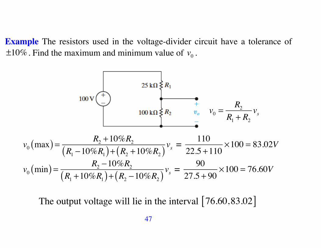
Example The resistors used in the voltage-divider circuit have a tolerance of ±10% . Find the maximum and minimum value of v0 .
v0 =R2
R1 + R2vs
v0 max( ) = R2 +10%R2
R1 !10%R1( ) + R2 +10%R2( ) vs = 11022.5 +110
!100 = 83.02V
v0 min( ) = R2 !10%R2R1 +10%R1( ) + R2 !10%R2( ) vs = 90
27.5 + 90!100 = 76.60V
The output voltage will lie in the interval 76.60,83.02[ ]

48
Multiple-Resistor Networks
i = vR1 + ....+ Rn
= vReq
vj = iRj =Rj
Reqv Voltage Division Equation

49
B. Current Division/ Single Node Circuit
v = i1R1 = i2R2 & v = R1R2
R1 + R2is
i1 =R2
R1 + R2
larger R2 larger i1
!"#$is , i2 =
R1R1 + R2
is

50
Example Find the power dissipated in the 6! resistor
P6! = i6! " v6! = 6 " i6!2
10 R4||6 = 2.4
R1.6!4||6 = 410
i4
R1.6+4||6 = 4"
CD : i4 =16
16 + 4!10 = 8A

51
8Ai6
CD : i6 =44 + 6
! 8 = 3.2A
P6! = 3.22 " 6 = 61.44W

52
Multiple-Resistor Networks
v = i ! Req ; Req =
11Rll
!
i j =vRj
! ij =ReqRj
i Current Division Equation

53
Example Use CD to find i0 and use VD to find v0
Req = 36 + 44( ) ||10 || (40 +10 + 30) || 24 = 6 !
CD: i0 =Req24
! 8 = 2A

54
The voltage drop across 40!10! 30
2A
v40!10!30 = 24 " 2 = 48VBy VD we have v0 =
3040 +10 + 30
v40!10!30 = 3080
! 48 = 18V

55
Example

56
+!
!
+
KCL: 16mA+I2 ! I1 = 0
CD: I1 =120
120 + 40!16 = 12 mA
! I2 = 12 !16 = !4 mA
! P40k! = I12 " 40k! = 5.76W

57
Example

58
+
I1
I2
I3
KCL: !6 ! I1 ! I2 + 4 ! I3 = 0 ! !2 = I1 + I2 + I3
4 ||12 = 3 k!

59
!2mA 3k"I2
CD: I2 =33+ 6
! "2mA( ) = " 23mA
P6k! = 6 "103( )" I22 = 6 !103( )! " 23
#$%
&'(2
!10"6 = 2.67mW

60
2.5. Measuring Resistance: The Wheatstone Bridge
Galvanometer µA( )
R1,R2 ,R3 - known resistors; Rx - unknown resistor
To find Rx we adjust R3 until there is no current in Galvanometer, i.e., ig = 0 .

61
Let ig = 0 , i.e., the bridge is balanced ! KCL: i1 = i3 , i2 = ix
By KVL (points a and b are at the same potential):
i3R3 = ixRx , i1R1 = i2R2
i1 = i3 , i2 = ix

62
i3R3 = ixRx , i1R1 = i2R2 ; i1 = i3 , i2 = ix ! i1R3 = i2Rx
i1R1 = i2R2 !
R3R1
= Rx
R2
!
Rx =R2R1
! R3

63
Rx =R2R1R3
• The range of Rx : 1! - 1 M!
• The range of R3 : 1! - 11 k!

64
2.6 ! ! Y ( ! ! T ) Transformations (Delta ! Wye)
v Req!
A resistive network generated by a Wheatstone bridge circuit
65
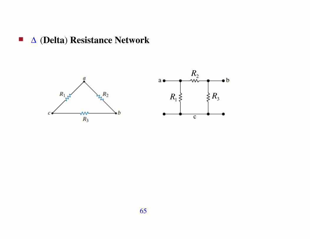
! (Delta) Resistance Network
R2
R1 R3

66
Y (Wye) Resistance Network
Ra Rb
Rc

67
! ! Y Equivalent Circuits
R2
R1 R3
Ra Rb
Rc
! Y
• Terminal c, a: Rca= R1 || R2 + R3( ) Rca = Ra + Rc

68
• Terminal b, c: Rbc= R3 || R1 + R2( ) Rbc = Rb + Rc
R2
R1 R3
Ra Rb
Rc
! Y
a
c
b b
c
aR3 R1
R2 Rb Ra
Rc
• Terminal a, b: Rab= R2 || R1 + R3( ) Rab = Ra + Rb

69
For a given ! network the equivalent Y network is obtained by setting
R2 R1 + R3( )R1 + R2 + R3
= Ra + Rb
R3 R1 + R2( )R1 + R2 + R3
= Rb + Rc
R1 R2 + R3( )R1 + R2 + R3
= Ra + Rc

70
Ra =R1R2
R1 + R2 + R3 ; Rb =
R2R3R1 + R2 + R3
; Rc =R1R3
R1 + R2 + R3
71
For a given Y network the equivalent ! network is obtained by setting
! Y

72
Example* Find the current and power supplied by the 40 V source.
We wish to replace the upper ! network by the equivalent Y network

73
Rc
Ra
Rb
Ra = 100 !125100 +125 + 25
= 50"
Rb = 125 ! 25100 +125 + 25
= 12.5"
Rc = 100 ! 25100 +125 + 25
= 10"

74
The equivalent circuits
Req = 55 +
10 + 40( )! 12.5 + 37.5( )10 + 40( ) + 12.5 + 37.5( ) = 55 + 50 ! 50
100 = 80!
! i40V = 4080
= 0.5A P40V = 40 ! 0.5 = 20W

75
Example

76
!
Ra =54 ! 36108
=18k"
Rb = 6k"Rc = 9k"
Ra = 18k"
Rb =18 ! 36108
= 6k"
Rc =18! 54108
= 9k"
RT = 6 +18 + 9 + 3( ) || 6 +18( ) + 2 = 34 k!

77
Example
!

78
4
4 4
1212
V0
V0 = 12k!" 4mA2
symmetry!
= 24V

79
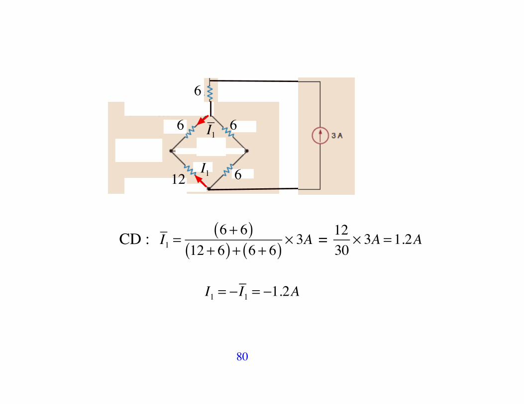
Example
80
6
66
12 6I1
I1
CD : I1 =6 + 6( )
12 + 6( ) + 6 + 6( ) ! 3A = 1230
! 3A = 1.2A
I1 = !I1 = !1.2A

81
Electrical Safety

82
2.7 Circuits with Dependent Sources

83
Example
KVL: !12 + 3I1 !VA + 5I1 = 0 and VA = 2000I1 ! I1 = 2mA
V0 = 5k ! I1 = 10V
84
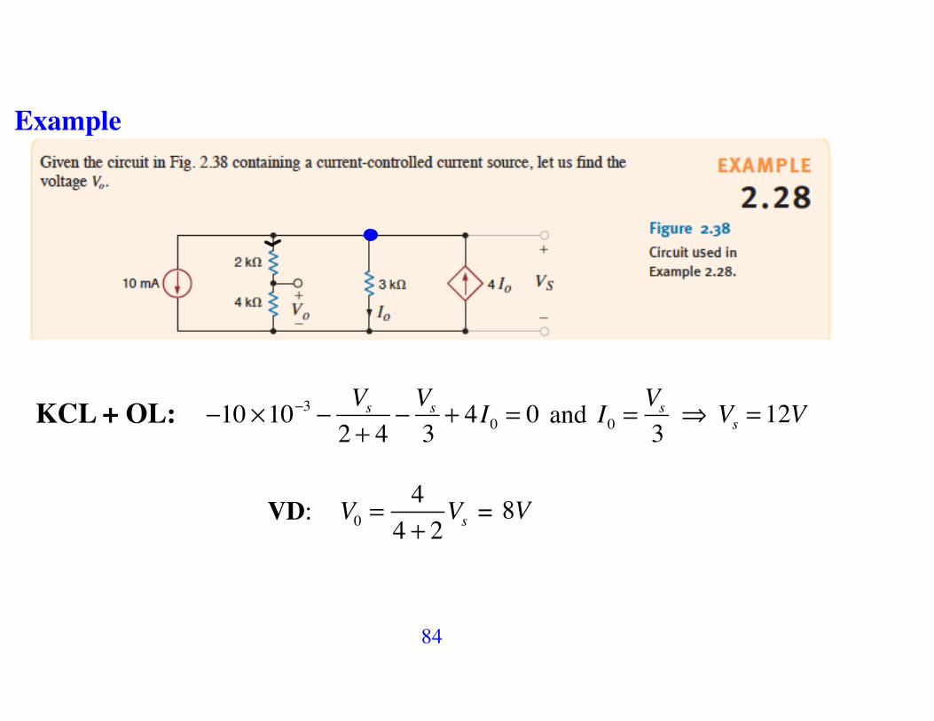
Example
KCL + OL: !10 "10!3 ! Vs
2 + 4! Vs3+ 4I0 = 0 and I0 =
Vs3
! Vs = 12V
VD: V0 =44 + 2
Vs = 8V

85
Example
KVL: !6 + 4I ! 2VA + 8I = 0 and VA = 4I ! I = 1.5mA
V0 = 1.5 ! 8 = 12V
86
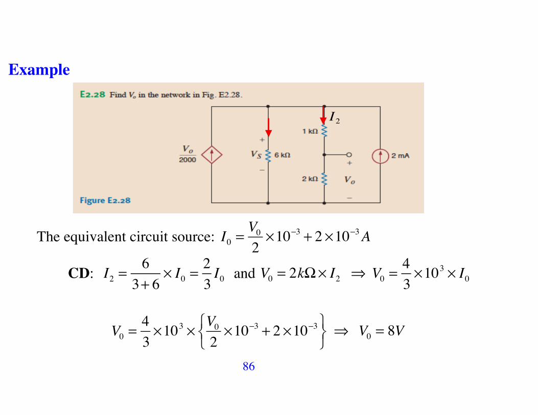
Example
I2
The equivalent circuit source: I0 =V02!10"3 + 2 !10"3A
CD: I2 =63+ 6
! I0 =23I0 and V0 = 2k!" I2 ! V0 =
43!103 ! I0
V0 =43!103 ! V0
2!10"3 + 2 !10"3#
$%
&'(
! V0 = 8V

87
Example
I2I3
• The equivalent circuit source: I0 = 6 !10"3 + 0.5Ix A
• 6 ||12 = 4 k!
• CD: Ix =4
4 + 4! I0 ! Ix = 4mA ! I0 = 6 + 2 = 8mA
• CD: I2 =4
4 + 4! I0 = 4mA and I3 =
66 +12
! I2 =43mA
• V0 = 12 !43= 16V

88
2.8. Analyzing Circuits Containing V/C Sources and Interconnection of Resistors: Examples
Example
V0 = 2V

89
I I1
Req=60 ! 3060 + 30
= 20k"
• I = 12V20k + 20k
= 0.3mA
• CD : I1 =30
30 + 40 + 20( ) I = 0.1mA ! V0 = 20k!" I1 = 2V

90
Example
I1
• I1 =3V30k!
= 0.1mA
• CD: I1 =60
60 + 90 + 30( ) IS =13IS ! IS = 3I1 = 0.3mA

91
Example
I1 I2
• The equivalent circuit source: I0 = 10mA
• CD : I1 =6
6 + 3+ 6( ) I0 = 4mA
• V1 = 3k ! I1 = 12V

92
Example
I1
I2
• CD : I2 =12
3 || 6 + 4( )+12 ! 9mA = 6mA
• CD : I1 =63+ 9
I2 = 4mA ! I0 = !I1 = !4mA

93
Example
I1
I2 I3

94
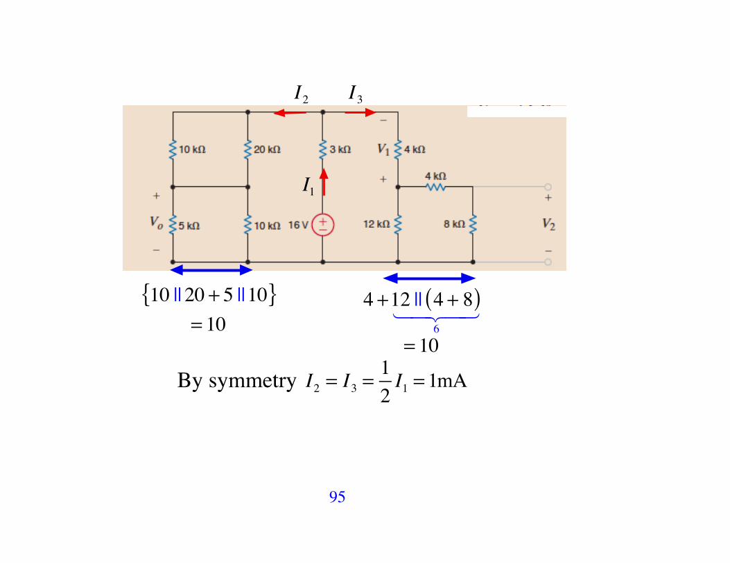
• Equivalent Circuits
I3I2
I1
I1 Req = 10 || 20 + 5 ||10{ } || 4 +12 || 4 + 8( )
6! "# $#
!"#
$#
%&#
'#= 5
I1 =16V3k + 5k
= 2mA
95
I3I2
I1
10 || 20 + 5 ||10{ }= 10
4 +12 || 4 + 8( )6
! "# $#
= 10
By symmetry I2 = I3 =12I1 = 1mA

96
I3I2
I1 2mA
1mA1mA
CD: I5k! = 105 +10
I2 =23mA ! V0 = 5k ! I5k" = 3.33V
OL: V1 = 4k ! "I3( ) = "4V

97
I3I2
I1 2mA
1mA1mA
I4
CD : I4 =12
12 + 4 + 8( ) ! I3 = 0.5mA
V2 = 8k ! I4 = 4V

98
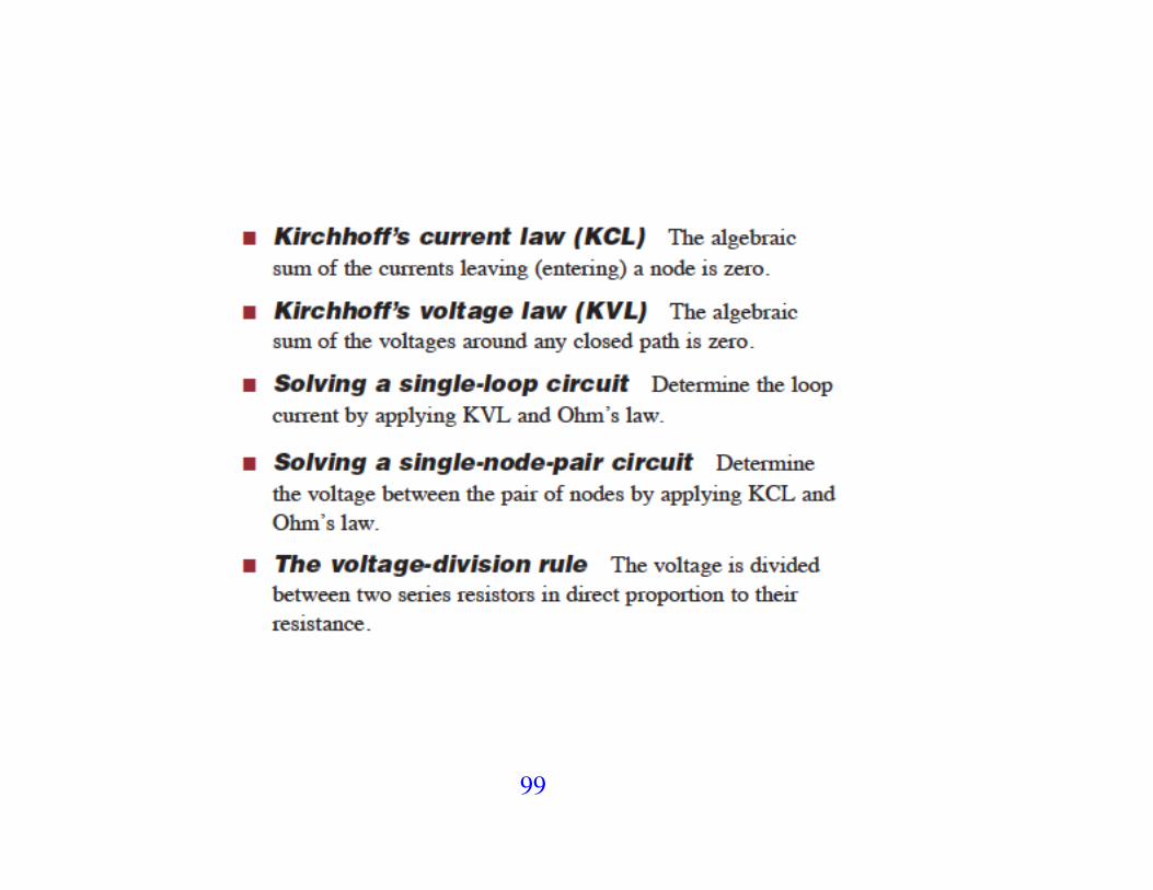
2.9 Summary of Chapter 2
99

100

101
2.10 Problems ! Tutorial


