ECE/CS 252 Fall 2011 Homework 4 (25 points) // Due in Lecture Mon Oct. 17, 2011 Instructions: You should do this homework in groups. You should hand in ONE copy of the homework that lists your section number and names and UW ID numbers of all students. You must staple all pages of your homework together to receive full credit. Warning: Most homeworks will use questions from your textbook, Patt and Patel's Introduction to Computing Systems, which we abbreviate (ItCS). First contact for questions is TA Ripudaman Singh: [email protected]Problem 1 (4+3+2 points) a. In this problem, your task is to design a finite state machine for a simple vending machine. Assume all the items are available for 15 cents and the machine can take in 5 cents or 10 cents as inputs. If at least 15 cents have been put into the machine, it’ll output the item selected but no change will be given back. Draw the state machine to model the behavior. Hint: A state should represent how much money has been put in. b. Draw the truth table and corresponding combinational logic for next states and output. c. What changes will you make to the state diagram you made in previous question if you need to return change as well? Draw the updated state diagram. Hint: Another output signal and state needs to be defined. Solution: Ideally 2 inputs should be considered but single input cases are also being given credit. Considering 2-inputs: a. State Diagram: Output X = 1 when we have received 15 cents or more. Input 00 means that no coin has been inserted Input 01 means that 5 cents coin has been inserted Input 10 means that 10 cents coin has been inserted Input 11 is not possible and hence ignore.
Transcript
ECE/CS 252 Fall 2011 Homework 4 (25 points) // Due in Lecture Mon Oct. 17, 2011 Instructions: You should do this homework in groups. You should hand in ONE copy of the homework that lists your section number and names and UW ID numbers of all students. You must staple all pages of your homework together to receive full credit. Warning: Most homeworks will use questions from your textbook, Patt and Patel's Introduction to Computing Systems, which we abbreviate (ItCS). First contact for questions is TA Ripudaman Singh: [email protected]
Problem 1 (4+3+2 points) a. In this problem, your task is to design a finite state machine for a simple vending machine. Assume all the items are available for 15 cents and the machine can take in 5 cents or 10 cents as inputs. If at least 15 cents have been put into the machine, it’ll output the item selected but no change will be given back. Draw the state machine to model the behavior. Hint: A state should represent how much money has been put in. b. Draw the truth table and corresponding combinational logic for next states and output. c. What changes will you make to the state diagram you made in previous question if you need to return change as well? Draw the updated state diagram. Hint: Another output signal and state needs to be defined. Solution: Ideally 2 inputs should be considered but single input cases are also being given credit. Considering 2-inputs:
a. State Diagram:
Output X = 1 when we have received 15 cents or more. Input 00 means that no coin has been inserted Input 01 means that 5 cents coin has been inserted Input 10 means that 10 cents coin has been inserted Input 11 is not possible and hence ignore.
b. Truth table
Input Current State Next State
I1 I0 S1 S0 S1’ S0’
0 0 0 0 0 0
0 0 0 1 0 1
0 0 1 0 1 0
0 0 1 1 0 0
0 1 0 0 0 1
0 1 0 1 1 0
0 1 1 0 1 1
0 1 1 1 0 1
1 0 0 0 1 0
1 0 0 1 1 1
1 0 1 0 1 1
1 0 1 1 1 0
Current State Output
S1 S0 X
0 0 0
0 1 0
1 0 0
1 1 1
X = S1 AND S0
S1’ = [(NOT I1) AND (NOT I0) AND (S1) AND (NOT S0)] OR
[(NOT I1) AND (I0) AND (S1) AND (NOT S0)] OR
[(NOT I1) AND (I0) AND (NOT S1) AND (S0)] OR
[(I1) AND (NOT I0) AND (NOT S1) AND (NOT S0)] OR
[(I1) AND (NOT I0) AND (NOT S1) AND (S0)] OR
[(I1) AND (NOT I0) AND (S1) AND (NOT S0)] OR
[(I1) AND (NOT I0) AND (S1) AND (S0)]
S0’ = [(NOT I1) AND (NOT I0) AND (NOT S1) AND (S0)] OR
[(NOT I1) AND (I0) AND (NOT S1) AND (NOT S0)] OR
[(NOT I1) AND (I0) AND (S1) AND (NOT S0)] OR
[(NOT I1) AND (I0) AND (S1) AND (S0)] OR
[(I1) AND (NOT I0) AND (NOT S1) AND (S0)] OR
[(I1) AND (NOT I0) AND (S1) AND (NOT S0)]
There can be other solutions to S1’ and S0’ for the state diagram given.
c. Output Y denotes if change is to be given or not
Y = 0 means no change
Y = 1 means change to be provided
Output X denotes if item is to be given out or not
X=1 only when we have 15 cents or more.
Considering 1 – input
a. State diagram
Output X=1 when we have 15 cents or more
Input I0 = 0 means 5 cents were inserted
Input I0 = 1 means 10 cents were inserted
b. Truth Table and logic expression
Input Current State Next State
I0 S1 S0 S1’ S0’
0 0 0 0 1
0 0 1 1 0
0 1 0 1 1
0 1 1 0 0
1 0 0 1 0
1 0 1 1 1
1 1 0 1 1
1 1 1 0 0
Current State Output
S1 S0 X
0 0 0
0 1 0
1 0 0
1 1 1
S1’ = [(NOT I0) AND (NOT S1) AND (S0)] OR
[(NOT I0) AND (S1) AND (NOT S0)] OR
[(I0) AND (NOT S1) AND (NOT S0)] OR
[(I0) AND (NOT S1) AND (S0)] OR
[(I0) AND (S1) AND (NOT S0)]
S0’ = [(NOT I0) AND (NOT S1) AND (NOT S0)] OR
[(NOT I0) AND (S1) AND (NOT S0)] OR
[(I0) AND (NOT S1) AND (S0)] OR
[(I0) AND (S1) AND (NOT S0)]
X = S1 AND S0
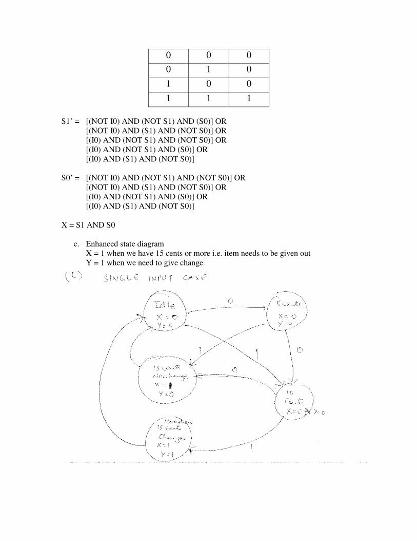
c. Enhanced state diagram
X = 1 when we have 15 cents or more i.e. item needs to be given out
Y = 1 when we need to give change
Problem 2 (3 points) Suppose a 32-bit instruction has a following format:
Opcode DR SR1 SR2 UNUSED
If there are 225 opcodes and 120 registers,
a. What is the minimum number of bits required to represent the OPCODE?
b. What is the minimum number of bits required to represent Destination reg?
c. What is the maximum number of UNUSED bits in the encoding?
Solution:
a. Minimum number of bits for opcodes: 8 (225 lies between 27 = 128 and 28 = 256)
b. Minimum number of bits required for Destination Reg: 7 (120 lies between 26 = 64 and 27 = 128)
c. Maximum number of UNUSED bits in the encoding: 32 - 8 - 7 – 7 - 7 = 32 - 29 = 3 (total bits = 32; opcode bits = 8; DR bits = 7; SR1 bits = 7; SR2 bits = 7)
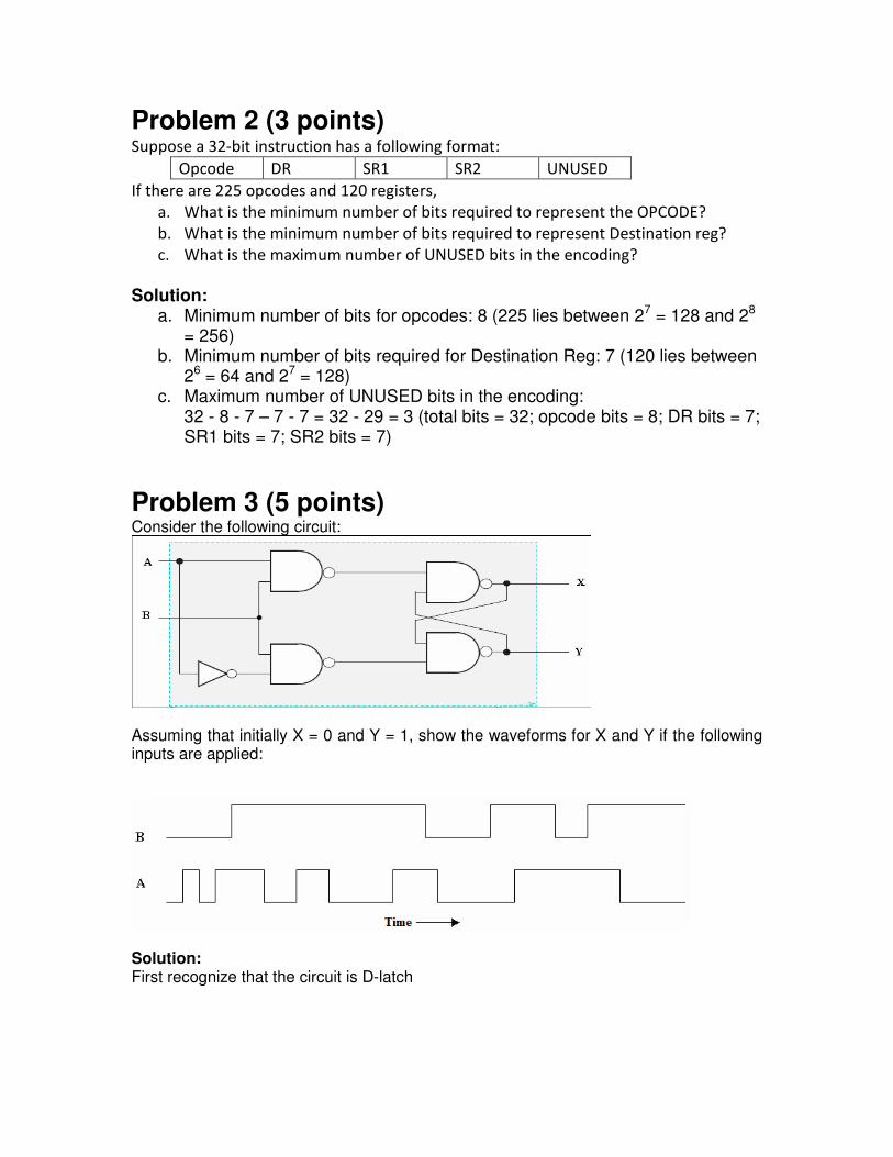
Problem 3 (5 points) Consider the following circuit:
Assuming that initially X = 0 and Y = 1, show the waveforms for X and Y if the following inputs are applied:
Solution: First recognize that the circuit is D-latch
Problem 4 (2 points) Given a memory that is addressed by 22 bits and is 3-bit addressable, how many bits of
storage does memory contain?
Solution:
Address Bits = 22
Number of entries = 222
Addressability = number of bits in each entry = 3 bits
Total number of bits of storage = Number of entries * Number of bits in each entry
= 222
* 3
Problem 5 (6 points)
The following table represents a small memory. Refer to this table for the following questions:
Address (in hex)
Data
0000 0000 0000 0000 0001 1110 0100 0011
0000 0000 0000 0001 0101 1010 0110 0101
0000 0000 0000 0010 1111 1010 1100 1110
0000 0000 0000 0011 1111 1111 0011 0001
0000 0000 0000 0100 0000 0100 1100 1111
0000 0000 0000 0101 0101 0100 0110 1111
0000 0000 0000 0110 0000 0010 0001 1001
0000 0000 0000 0111 0000 0000 0000 0001
a. What hexadecimal value does address 0x2 contain? What about address 0x5?
b. Interpret value at address 0x3 as a 2's complement integer.
c. Interpret value at address 0x1 as an ASCII value.
d. Interpret value at address 0x4 as an unsigned integer.
e. In the von Neumann model, the contents of an entry in memory can be
interpreted as an instruction. If the binary patterns in address 0x6 and address
0x0 were interpreted as a LC-3 instruction, what instructions would they
represent?
Hint: Refer to appendix A.3 for complete instruction set of LC-3 (Page 525 of
ltCS).
f. A binary value can also be interpreted as a memory address. If the value stored
in address 0x7 is a memory address, to what address does it refer? What binary