1 1 ECET 211 Electric Machines & Controls Lecture 9-1 Adjustable-Speed Drives and PLC Installations (1 of 2) Text Book: Electric Motors and Control Systems, by Frank D. Petruzella, published by McGraw Hill, 2015. Paul I-Hai Lin, Professor of Electrical and Computer Engineering Technology P.E. States of Indiana & California Dept. of Computer, Electrical and Information Technology Purdue University Fort Wayne Campus Prof. Paul Lin Lecture 9-1 Adjustable-Speed Drives and PLC Installations (1 of 2) A Quick Overview of Motor Control Electronics (Chapter 9) • Diodes, Transistors, Thyristors and ICs Part 1. AC Motor Drive Fundamentals • Variable-Frequency Drives (VFD) • Volts per Hertz Drive • Flux Vector Drive Part 2. VFD Installation and Programming • Parameters • Selecting the Drive • Lines and Load Reactors • Location • Enclosures Prof. Paul Lin 2 • Mounting Techniques • Operator Interface • Electromagnetic Interference • Grounding • Bypass Contactor • Disconnecting Means • Motor Protection • Braking • Ramping • Control Inputs and Outputs • Motor Nameplate Data • Derating • Types of Variable-Frequency Drives • PID control • Parameter Programming • Diagnostics and Troubleshooting
Transcript
1
1
ECET 211 Electric Machines & Controls
Lecture 9-1
Adjustable-Speed Drives and PLC Installations
(1 of 2)
Text Book: Electric Motors and Control Systems, by Frank D. Petruzella, published by McGraw Hill, 2015.
Paul I-Hai Lin, Professor of Electrical and Computer Engineering Technology
P.E. States of Indiana & California
Dept. of Computer, Electrical and Information Technology
Purdue University Fort Wayne Campus
Prof. Paul Lin
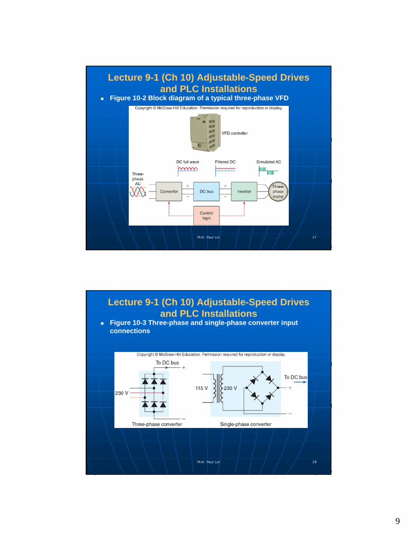
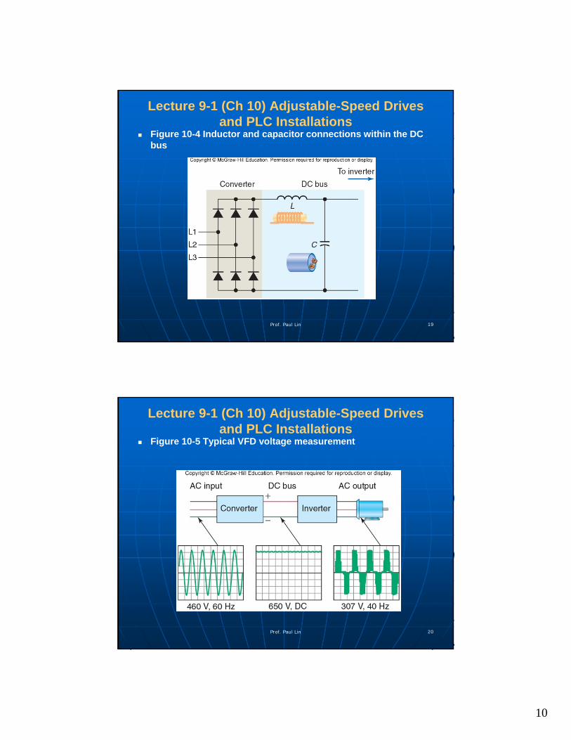
Lecture 9-1 Adjustable-Speed Drives and PLC Installations (1 of 2)
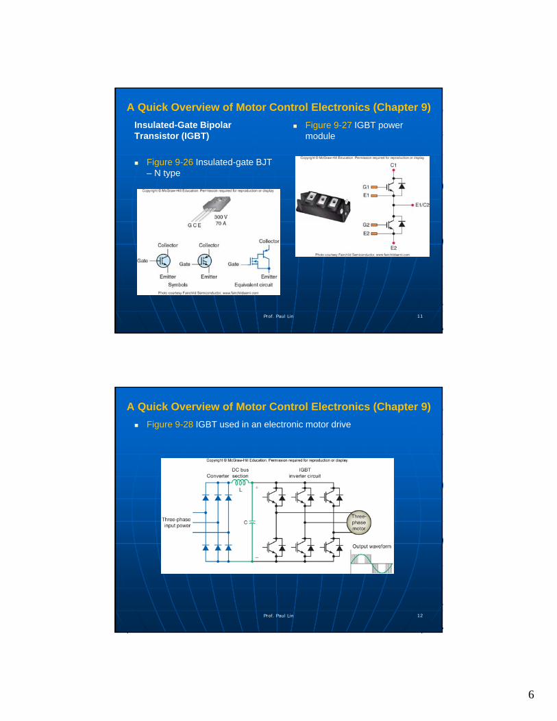
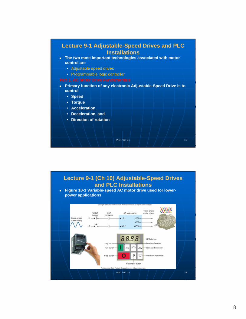
A Quick Overview of Motor Control Electronics (Chapter 9)
• Diodes, Transistors, Thyristorsand ICs
Part 1. AC Motor Drive Fundamentals
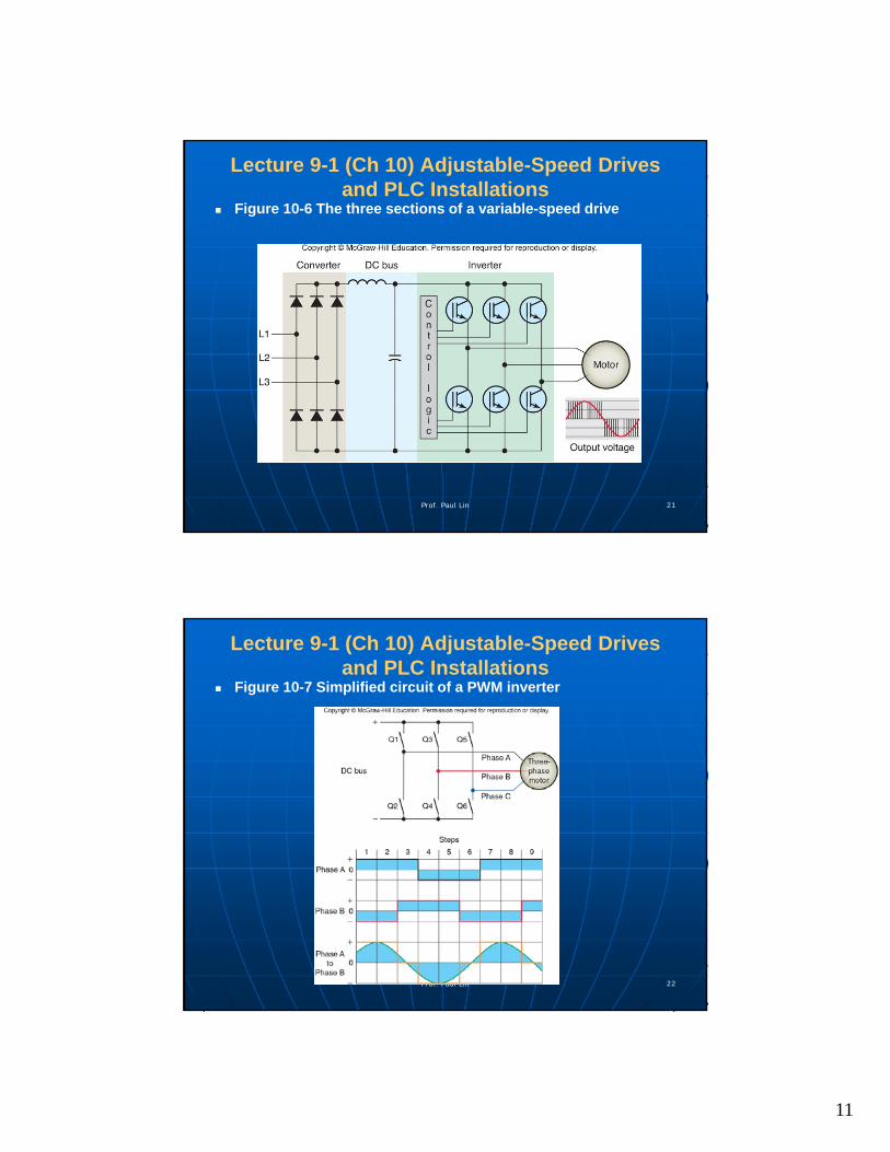
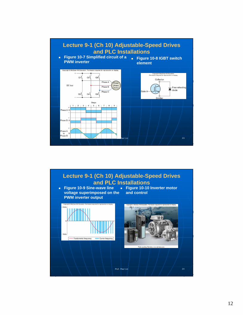
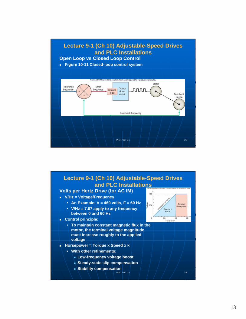
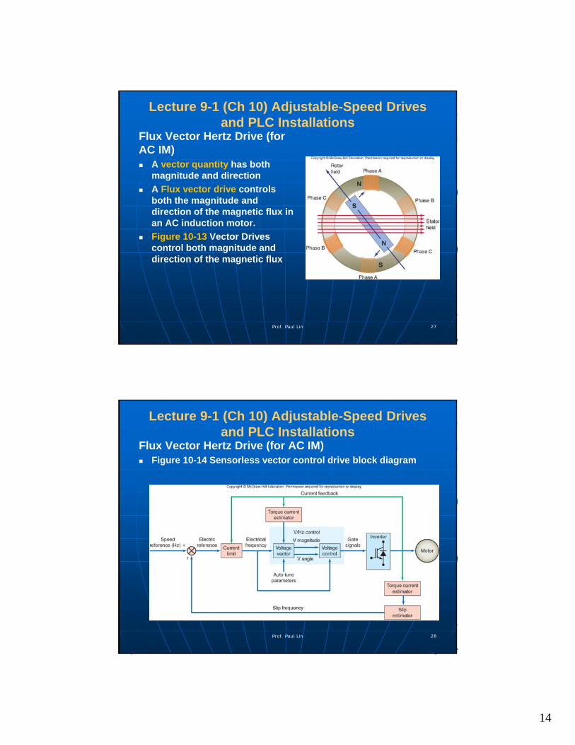
• Variable-Frequency Drives (VFD)
• Volts per Hertz Drive
• Flux Vector Drive
Part 2. VFD Installation and Programming
• Parameters
• Selecting the Drive
• Lines and Load Reactors
• Location
• Enclosures
Prof. Paul Lin 2
• Mounting Techniques
• Operator Interface
• Electromagnetic Interference
• Grounding
• Bypass Contactor
• Disconnecting Means
• Motor Protection
• Braking
• Ramping
• Control Inputs and Outputs
• Motor Nameplate Data
• Derating
• Types of Variable-Frequency Drives
• PID control
• Parameter Programming
• Diagnostics and Troubleshooting
2
Lecture 9-1 Adjustable-Speed Drives and PLC Installations
Part 3. DC Motor Drive Fundamentals (SKIP)
• Applications
• DC Drives – Principles of Operation
• Single-Phase Input – DC Drive
• Three-Phase Input – DC Drive
• Field Voltage Control
• Non-regenerative and Regenerative DC Drives
• Parameter Programming
Prof. Paul Lin 3
Part 4. Programmable Logic Controllers (PLCs)
• PLC Sections and Configurations
• Ladder Logic Programming
• Programming Timers
• Programming Counters
Lecture 9-1 Adjustable-Speed Drives and PLC Installations
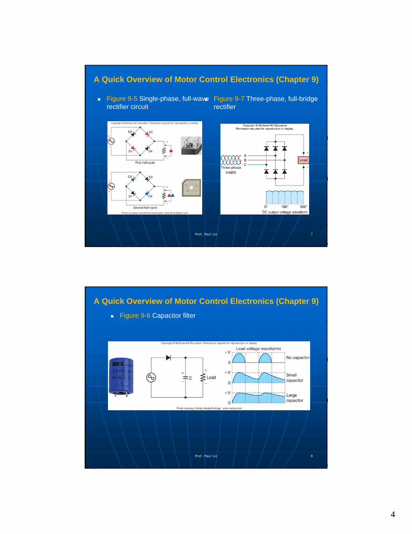
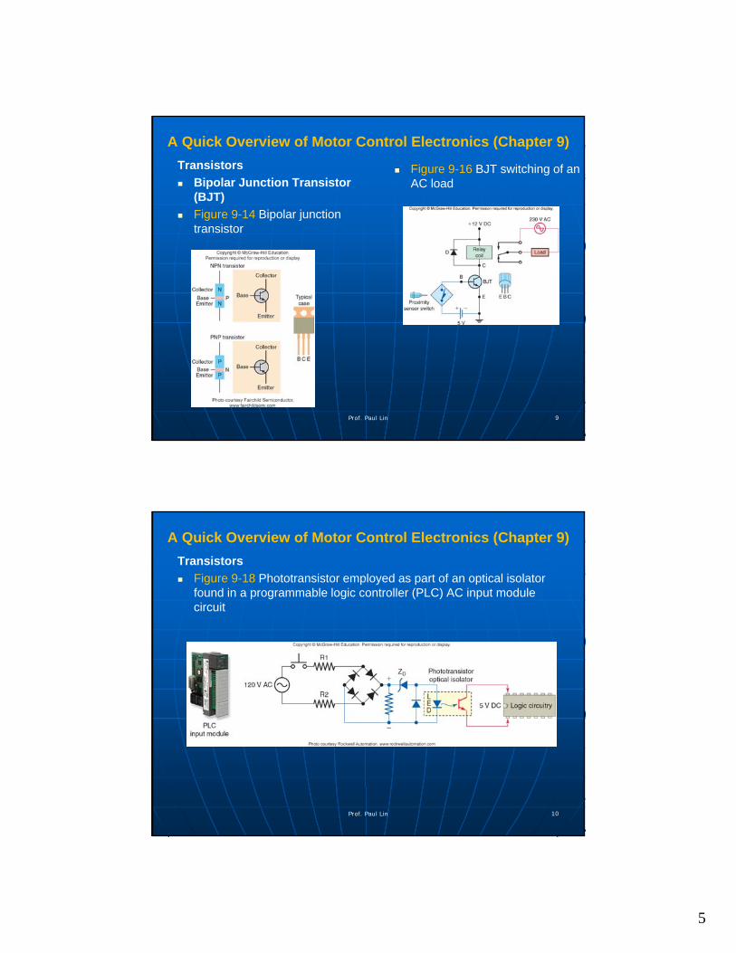
A Quick Overview of Motor Control Electronics (Chapter 9)
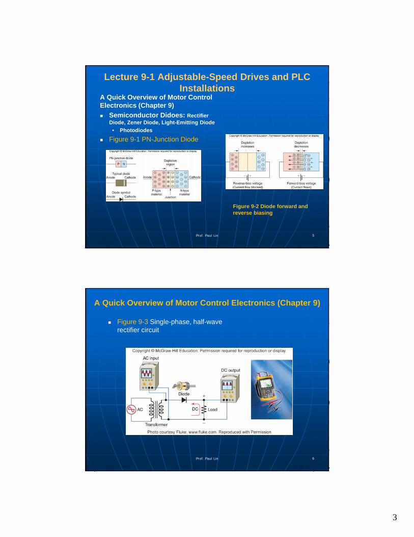
Semiconductor Didoes• Rectifier Diode
• Zener Diode
• Light-Emitting Diode
• Photodiodes
Transistors
Thyristors
ICs
Prof. Paul Lin 4
3
Lecture 9-1 Adjustable-Speed Drives and PLC Installations
A Quick Overview of Motor Control Electronics (Chapter 9)