38
Bioe594-1/26/2006 Echo Planar Imaging BioE 594 – Advanced Topics in MRI Nick Gruszauskas
Bioe594-1/26/2006
Echo Planar Imaging
BioE 594 – Advanced Topics in MRINick Gruszauskas
Bioe594-1/26/2006
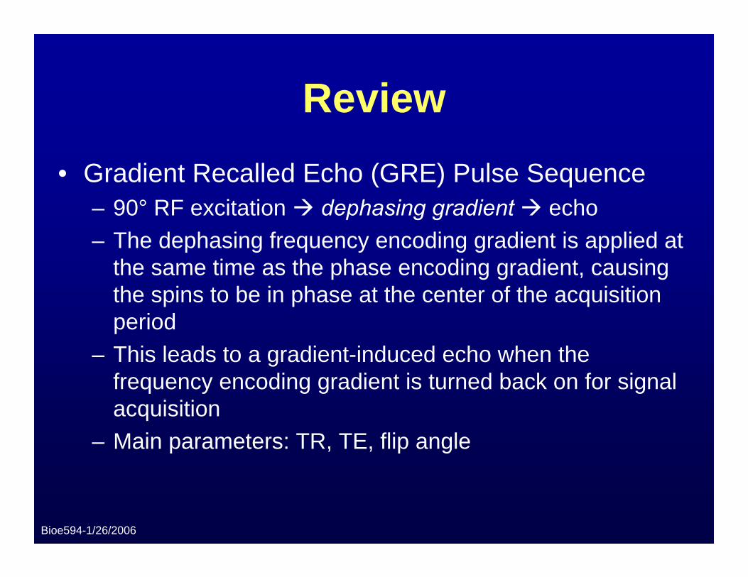
Review• Gradient Recalled Echo (GRE) Pulse Sequence
– 90° RF excitation dephasing gradient echo– The dephasing frequency encoding gradient is applied at
the same time as the phase encoding gradient, causing the spins to be in phase at the center of the acquisition period
– This leads to a gradient-induced echo when the frequency encoding gradient is turned back on for signal acquisition
– Main parameters: TR, TE, flip angle
Bioe594-1/26/2006
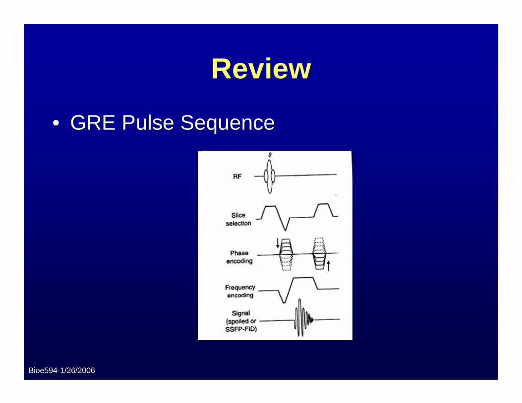
Review
• GRE Pulse Sequence
Bioe594-1/26/2006
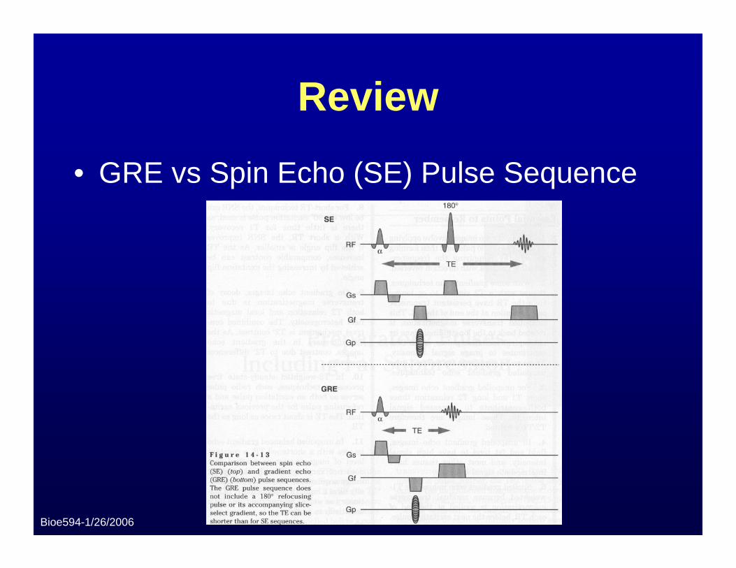
Review
• GRE vs Spin Echo (SE) Pulse Sequence
Bioe594-1/26/2006
Review
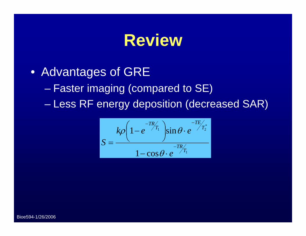
• Advantages of GRE– Faster imaging (compared to SE)– Less RF energy deposition (decreased SAR)
1
*21
cos1
sin1
TTR
TTE
TTR
e
eekS −
−−
⋅−
⋅⎟⎠⎞
⎜⎝⎛ −
=θ
θρ
Bioe594-1/26/2006
Review
• Disadvantages of GRE– Poor T2-weighted image quality (highly
susceptible to T2* effects)– Potentially large signal loss due to magnetic
field inhomogeneities and other off-resonance effects
Bioe594-1/26/2006
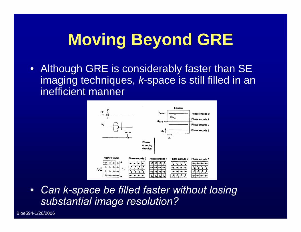
Moving Beyond GRE• Although GRE is considerably faster than SE
imaging techniques, k-space is still filled in an inefficient manner
• Can k-space be filled faster without losing substantial image resolution?
Bioe594-1/26/2006
Echo Planar Imaging
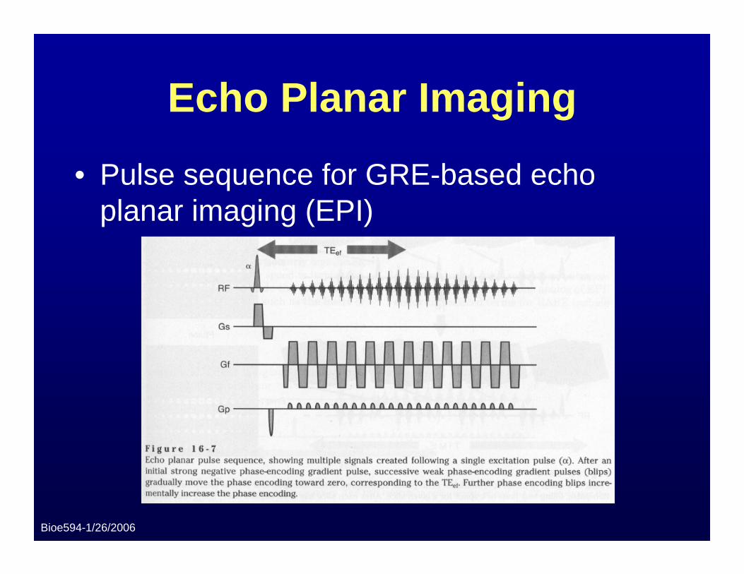
• Pulse sequence for GRE-based echo planar imaging (EPI)
Bioe594-1/26/2006
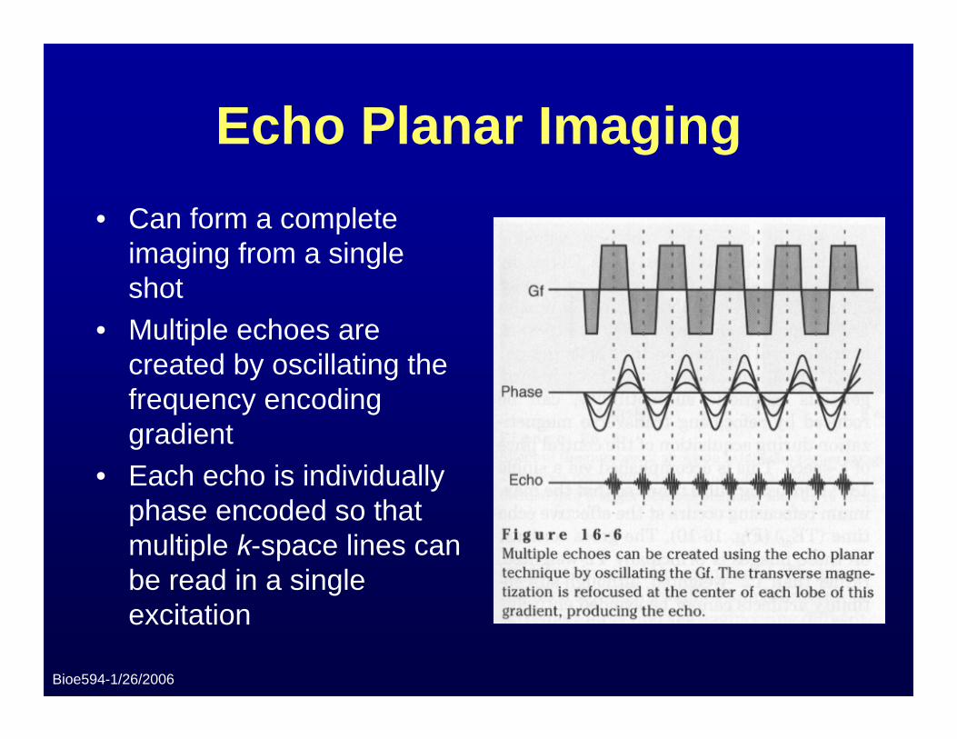
Echo Planar Imaging• Can form a complete
imaging from a single shot
• Multiple echoes are created by oscillating the frequency encoding gradient
• Each echo is individually phase encoded so that multiple k-space lines can be read in a single excitation

Bioe594-1/26/2006
Echo Planar Imaging
• Difference between GRE and EPI
Bioe594-1/26/2006
Echo Planar Imaging
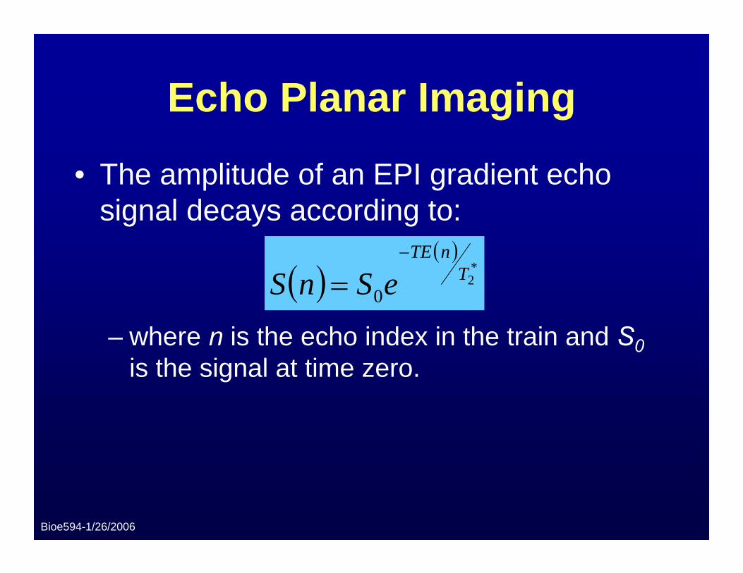
• The amplitude of an EPI gradient echo signal decays according to:
– where n is the echo index in the train and S0is the signal at time zero.
( )( )
*2
0T
nTE
eSnS−
=
Bioe594-1/26/2006
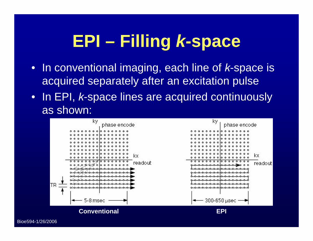
EPI – Filling k-space• In conventional imaging, each line of k-space is
acquired separately after an excitation pulse• In EPI, k-space lines are acquired continuously
as shown:
Conventional EPI
Bioe594-1/26/2006
EPI – Filling k-space
• Filling k-space in this manner results in drastically reduced acquisition times
• Variation of filling trajectories depends on the phase encoding gradient pattern used
• Image contrast is dependant on the RF sequence and not on the spatial encoding technique
Bioe594-1/26/2006
EPI – Basic Parameters• As in Fast Spin Echo (FSE), the following
parameters are used to define an EPI pulse sequence (where the ‘echoes’ are gradient echoes instead of spin echoes):– Echo Train Length (ETL)– Echo Spacing (ESP)– Effective Echo Time and Repetition Time (TEef and
TR)• ETL directly determines the amount of scan time
reduction• Contrast is largely determined by TEef
Bioe594-1/26/2006
Readout Gradient Parameters• The oscillation of the frequency encoding
gradient enables the rapid acquisition of lines in k-space as well as generating multiple gradient echoes
• Three different types of frequency encoding gradient waveforms are used in EPI:– Trapezoidal– Sinusoidal– Catch-and-hold (hybrid of trapezoid and sinusoid)
Bioe594-1/26/2006
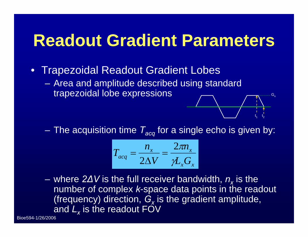
Readout Gradient Parameters• Trapezoidal Readout Gradient Lobes
– Area and amplitude described using standard trapezoidal lobe expressions
– The acquisition time Tacq for a single echo is given by:
– where 2ΔV is the full receiver bandwidth, nx is the number of complex k-space data points in the readout (frequency) direction, Gx is the gradient amplitude, and Lx is the readout FOV
xx
xxacq GL
nV
nTγπ2
2=
Δ=
t1 t2
Gx
Bioe594-1/26/2006
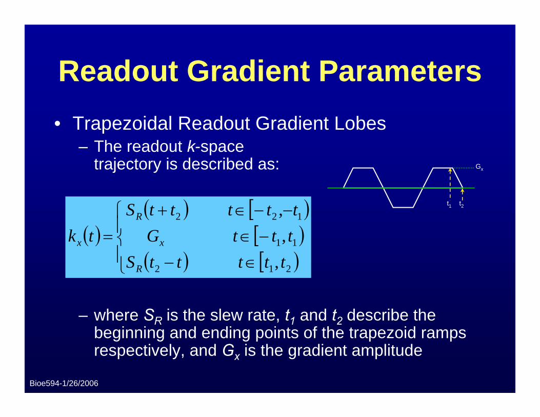
Readout Gradient Parameters• Trapezoidal Readout Gradient Lobes
– The readout k-space trajectory is described as:
– where SR is the slew rate, t1 and t2 describe the beginning and ending points of the trapezoid ramps respectively, and Gx is the gradient amplitude
t1 t2
Gx
( )( ) [ )
[ )( ) [ )⎪
⎩
⎪⎨
⎧
∈−−∈
−−∈+=
212
11
122
,,,
tttttStttGtttttS
tk
R
x
R
x
Bioe594-1/26/2006
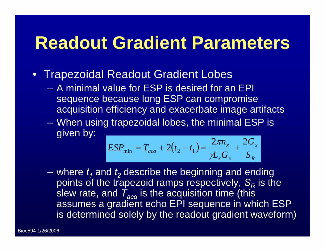
Readout Gradient Parameters• Trapezoidal Readout Gradient Lobes
– A minimal value for ESP is desired for an EPI sequence because long ESP can compromise acquisition efficiency and exacerbate image artifacts
– When using trapezoidal lobes, the minimal ESP is given by:
– where t1 and t2 describe the beginning and ending points of the trapezoid ramps respectively, SR is the slew rate, and Tacq is the acquisition time (this assumes a gradient echo EPI sequence in which ESP is determined solely by the readout gradient waveform)
( )R
x
xx
xacq S
GGLnttTESP 222 12min +=−+=
γπ
Bioe594-1/26/2006
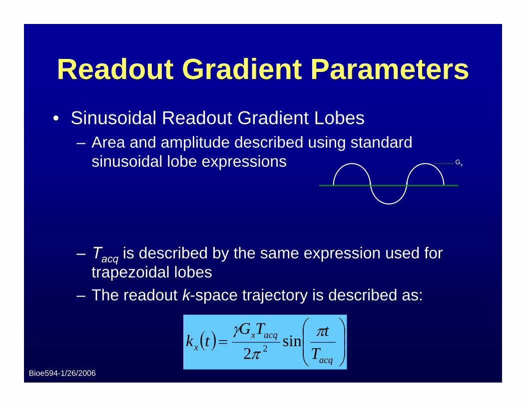
Readout Gradient Parameters• Sinusoidal Readout Gradient Lobes
– Area and amplitude described using standard sinusoidal lobe expressions
– Tacq is described by the same expression used for trapezoidal lobes
– The readout k-space trajectory is described as:
Gx
( ) ⎟⎟⎠
⎞⎜⎜⎝
⎛=
acq
acqxx T
tTGtk π
πγ
sin2 2
Bioe594-1/26/2006
Ramp Sampling
• Both trapezoidal and sinusoidal lobes contain ramping periods
• In order to further minimize ESP, k-space data can be acquired during these ramps (known as “ramp sampling”)– Helps minimize image artifacts (blurring, etc.)– Maintains acquisition efficiency without
increasing gradient slew rate
Bioe594-1/26/2006
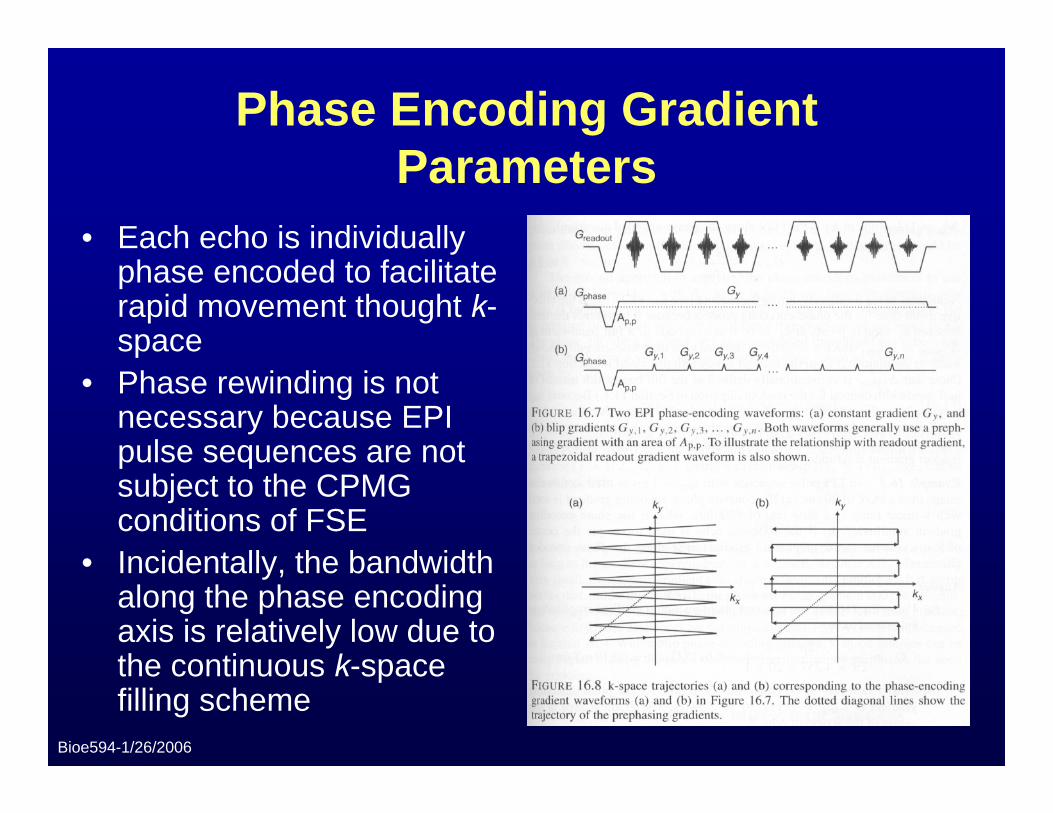
Phase Encoding Gradient Parameters
• Each echo is individually phase encoded to facilitate rapid movement thought k-space
• Phase rewinding is not necessary because EPI pulse sequences are not subject to the CPMG conditions of FSE
• Incidentally, the bandwidth along the phase encoding axis is relatively low due to the continuous k-space filling scheme
Bioe594-1/26/2006
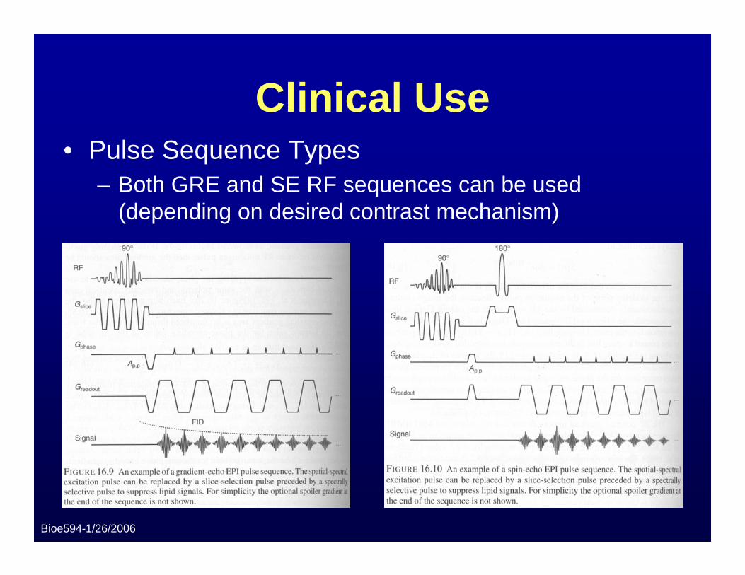
Clinical Use• Pulse Sequence Types
– Both GRE and SE RF sequences can be used (depending on desired contrast mechanism)
Bioe594-1/26/2006
Clinical Use
• Single-Shot EPI– Entire 2D k-space data needed for image
reconstruction obtained using an echo train generated by a single excitation pulse
• Multi-Shot EPI– A fraction of the k-space needed to
reconstruct the image is obtained with each echo train

Bioe594-1/26/2006
Clinical Use
• Single-Shot EPI– The total scan time (assuming no averaging) is
given by:
– where C is the interval between the start of the sequence and the beginning of data acquisition
• Multi-Shot EPI– The total scan time is given by:
( )ESPETLCNT slicescan ⋅+=
acqshotscan NNEXNTRT ⋅⋅⋅=
Bioe594-1/26/2006
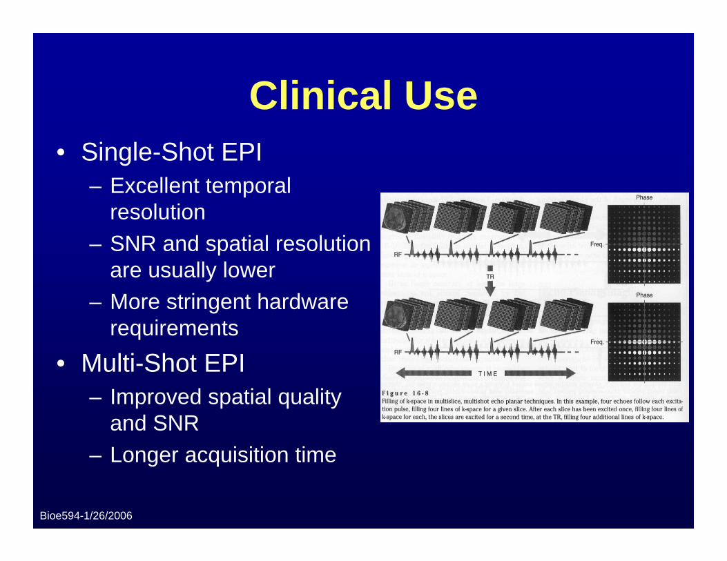
Clinical Use• Single-Shot EPI
– Excellent temporal resolution
– SNR and spatial resolution are usually lower
– More stringent hardware requirements
• Multi-Shot EPI– Improved spatial quality
and SNR– Longer acquisition time
Bioe594-1/26/2006
Homework Problem #1
• When determining the scan time for a single-shot EPI sequence in which signal averaging is not used, why isn’t TR a factor? How would the formula for calculating the scan time change if signal averaging were used?– Hint: What is the definition of TR and what
effect does it have in single-shot EPI?
Bioe594-1/26/2006
Signal-to-Noise Ratio• EPI has considerably lower SNR when compared to SE
or FSE due to:– Higher susceptibility to off-resonance effects– Extremely wide receiver bandwidths needed for fast data
acquisition
• In theory the SNR is about one-third that of conventional imaging due to bandwidth differences alone
• In practice the SNR is comparable to conventional imaging sequences because of:– Imaging techniques such as increased Nacq, signal averaging,
careful selection of TR, ETL, etc.– Inherent reduced motion artifact– Reduced imager instability
Bioe594-1/26/2006
Hardware Requirements• EPI is a demanding pulse sequence that requires:
– High performance gradients with rapid rise times (slew rates of ~100 T/m/sec or higher for some systems)
– High peak amplitudes (~25 mT/m or higher for some systems)
– High receiver bandwidth (up to 300 kHz is typical)– Large amounts of power (2000 volts at 350 amps, or
750 kW, on a conventional system, for example)– Low eddy currents and field imhomogeneities– Fast analog-to-digital converters (up to 2 MHz)
Bioe594-1/26/2006
Patient Safety Considerations• Rapidly switched magnetic field gradients can
result in current induction in the patient– Induced current is proportional to the cross-sectional
area of the body exposed as well as the magnetic field
– Shorter and smaller gradient coils are used to localize the area of imaging
• High slew rates can cause pain, peripheral neurostimulation, induced respiration, and other problems– Frequency encoding gradient waveforms must be
designed with this factor in mind
Bioe594-1/26/2006
Advantages of EPI• Extremely fast image acquisition times
– Compare a canonical T2-weighted image scan time of about 384 seconds (128 samples with a TR of 3 sec) to a similar EPI scan at 40 to 150 milliseconds (~10,000-fold speed gain)
• Reduced motion artifacts• Reduced SAR from RF compared to SE sequences• Potential for functional imaging techniques
– GRE EPI can produce frame rates of up to 16 fps, suitable for cardiac imaging
– Ability to produce contrast from T2* behavior allows for blood oxygen-level dependent (BOLD) imaging and other functional techniques
Bioe594-1/26/2006
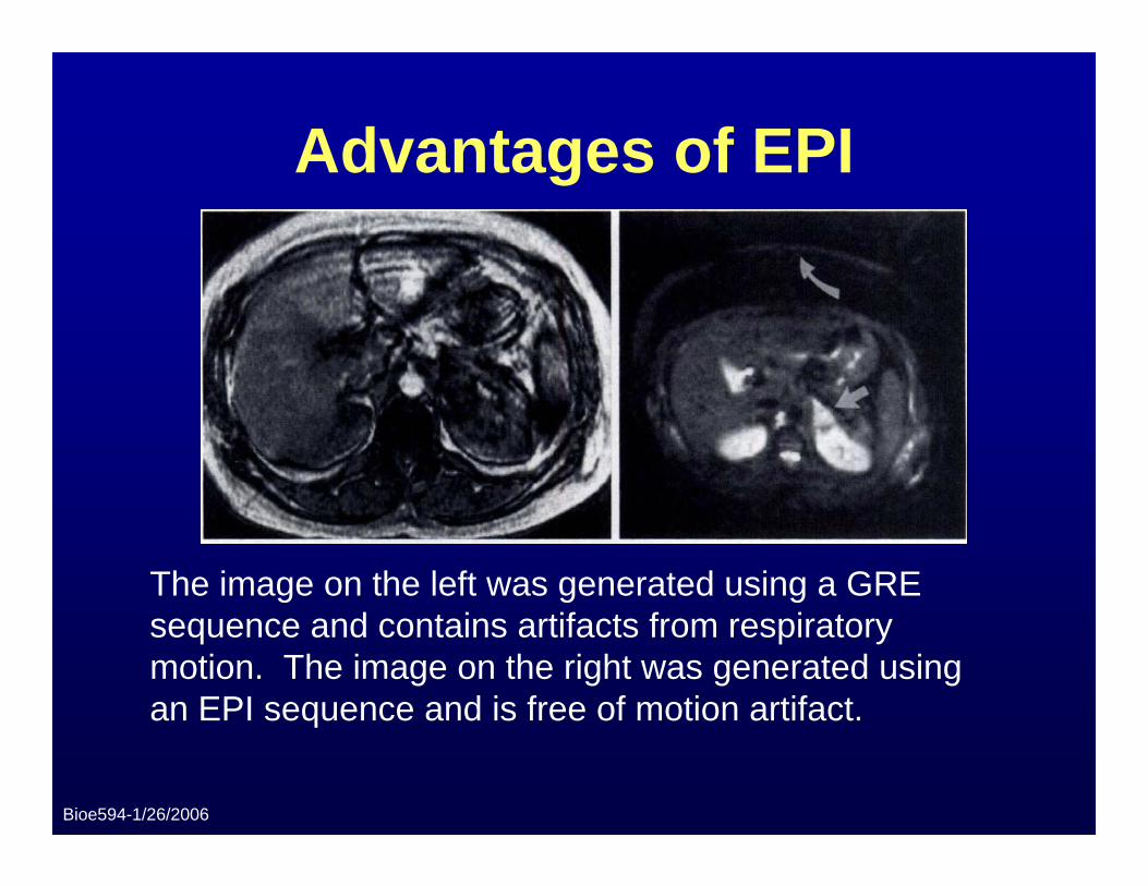
Advantages of EPI
The image on the left was generated using a GRE sequence and contains artifacts from respiratory motion. The image on the right was generated using an EPI sequence and is free of motion artifact.
Bioe594-1/26/2006
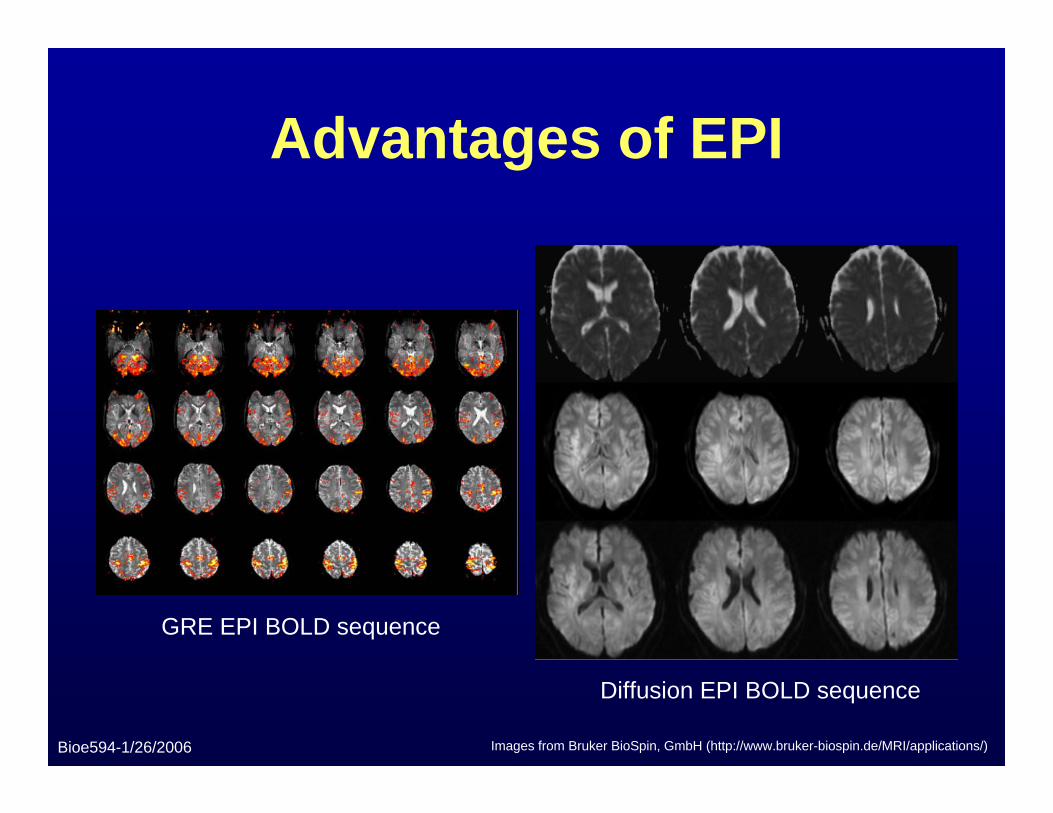
Advantages of EPI
GRE EPI BOLD sequence
Diffusion EPI BOLD sequence
Images from Bruker BioSpin, GmbH (http://www.bruker-biospin.de/MRI/applications/)
Bioe594-1/26/2006
Disadvantages of EPI• Highly susceptible to image artifacts
– Nyquist ghosting: gradient-induced eddy currents cause time-dependent frequency shifts, which in turn create phase differences from line to line in k-space because of the back and forth acquisition trajectories (this is exacerbated when row-flipping must be used to fill the k-space)
– Chemical shift artifacts: the low bandwidth along the phase-encoding direction (not the frequency-encoding direction) can cause substantial chemical shifting
– Image and shape distortion: field inhomogeneities and other off-resonance effects can cause considerable distortion along the phase-encoding direction due to low bandwidth
– T2* blurring: each line in k-space carries a different T2* weighting because they are acquired at different times
Bioe594-1/26/2006
Disadvantages of EPI
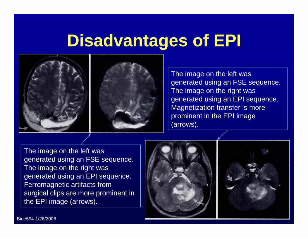
The image on the left was generated using an FSE sequence. The image on the right was generated using an EPI sequence. Ferromagnetic artifacts from surgical clips are more prominent in the EPI image (arrows).
The image on the left was generated using an FSE sequence. The image on the right was generated using an EPI sequence. Magnetization transfer is more prominent in the EPI image (arrows).
Bioe594-1/26/2006
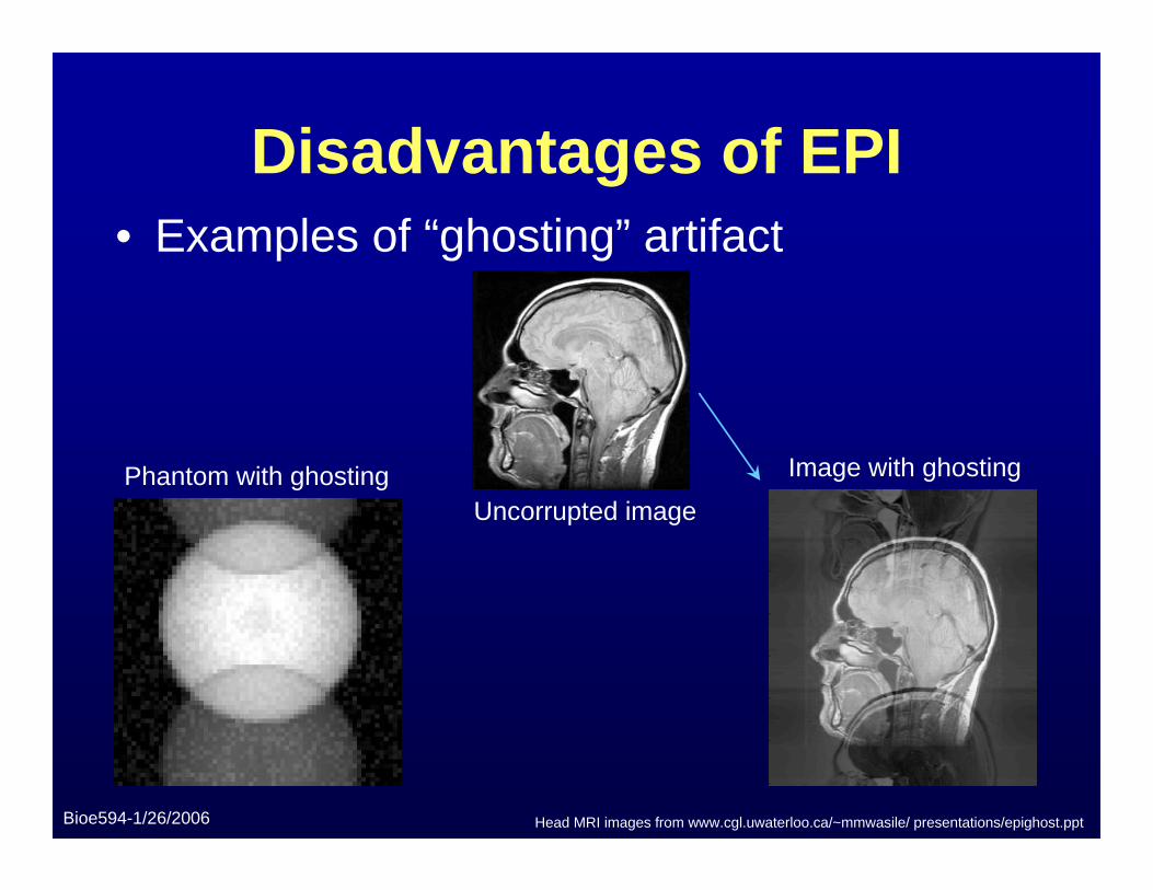
Disadvantages of EPI• Examples of “ghosting” artifact
Uncorrupted image
Image with ghostingPhantom with ghosting
Head MRI images from www.cgl.uwaterloo.ca/~mmwasile/ presentations/epighost.ppt
Bioe594-1/26/2006
Disadvantages of EPI• Many of these artifacts can be corrected or
compensated:– Use of gradient coils designed to minimize eddy
current induction– Use of reference images without phase encoding as a
basis for determining where time-dependent phase shifts have occurred (reduces ghosting)
– Fat suppression techniques (reduces chemical shift)– T2* mapping and multi-shot techniques can reduce
blurring– Decreasing the ESP or ETL, and active shimming
(reduces image and shape distortion)
Bioe594-1/26/2006
Homework Problem #2• An EPI scan using a trapezoidal readout gradient waveform
is performed using the following parameters:– Receiver bandwidth (ΔV) = ±62.5 kHz– nx = 128 points– Readout FOV = 22 cm– Slew rate = 120 T/m/sec
• Assume no ramp sampling was used. What is ESPmin? If the bandwidth is increased to ±125 kHz, what is ESPmin?
• Recalculate ESPmin for both receiver bandwidths (±62.5 kHz and ±125 kHz) using a reduced slew rate of 20 T/m/sec. Does increasing the bandwidth in this instance increase or decrease ESPmin? Why?– Hint: Think about the time necessary for ramping at this lower slew
rate.
Bioe594-1/26/2006
References and Figures from:1. Bernstein, M.A.; King, K.F.; Zhou, X.J., Handbook of MRI Pulse
Sequences. Elsiver/Academic Press: Burlington, MA, 2004.2. Mitchell, G.M.; Cohen, M.S., MRI Principles. Elsiver/Saunders:
Philadelphia, PA, 2004.3. DeLaPaz, R.L., “Echo-planar Imaging.” Radiographics 1994, 14, (5),
1045-1058.4. Cohen, M.S., Echo-planar imaging and functional MRI. Online, 1998.
<http://airto.loni.ucla.edu/BMCweb/BMC_BIOS/MarkCohen/Papers/EPI-fMRI.html>, accessed 17 Jan 2006.
5. Cohen, M.S.; Weisskoff, R.K., “Ultra-fast imaging.” Magn Reson Imaging1991, 9, (1), 1-37.
6. Tkach, J.A.; Haacke, E.M., “A comparison of fast spin echo and gradient field echo sequences.” Magn Reson Imaging 1998, 6, (4), 373-389.
7. Hornak, J.P., The Basics of MRI. Online, 2005. <http://www.cis.rit.edu/htbooks/mri/index.html>


