Eclipse tm Actuator Installation, Operations and Maintenance Manual Practical Safety Technology For Toxic Gas Handling Emergency Shutoff System Chlorine Cylinders and Ton Containers Bulletin: 200.13 4/08
Transcript
Eclipse tm Actuator
Installation, Operations and Maintenance
Manual
Practical Safety Technology For
Toxic Gas Handling
Emergency Shutoff System Chlorine Cylinders and Ton Containers
Bulletin: 200.13
4/08
These instructions generally describe the installation, operation and maintenance of Halogen Valve Systems’ automatic shutoff valve actuators. Halogen Valve Systems reserves the right to make engineering refinements that may not be described herein. Any questions that cannot be answered by these instructions should be directed to Halogen Valve Systems or your local sales representative.
Halogen Valve Systems takes all possible precautions in packaging each item to prevent shipping damage. Carefully inspect each item and report damages to the shipping agent, Halogen Valve Systems or your local sales representative. Inspect all packing materials and compare the items with the shipping paperwork before discarding to prevent loss of accessories, mounting-hardware or instructions.
Halogen Valve Systems or your local sales representative can provide technical consultation and personnel training on the installation and operation of these systems.
For more information concerning procedures for the handling of chlorine cylinders, refer to The Chlorine Manual published by The Chlorine Institute, Washington, DC.
4/08
17961 Sky Park Circle, Ste A Irvine, Ca. 92612
US Patent No. 5,588,637
Phone No. 949-261-5030 Toll Free 877-476-4222
Fax 949-261-5033
Halogen Web Site: www.halogenvalve.com
I. Introduction ............................................................. 1
A. General ............................................................. 1
B. Warranty ........................................................... 1
C. Standard Equipment. ...................................... 1
D. Specifications .................................................. 1
II. Operation ............................................................ 2
III. System Installation ............................................ 3
A. Control and Accessories ............................. 3-4
B. Wall Brackets …………………………………...4
C. Actuator Cable ................................................. 4
D. Input/Output Wiring ..................................... 5-6
E. 115 or 230 VAC Wiring .................................... 7
F. Emergency Close Circuit ............................... 7
G. Battery installation ....................................... 8-9
H. System Connection & Checks ..................9-10
IV. Mounting to a Cylinder Valve .......................... 10
A. Vacuum Regulator Direct Mounting ............ 11
B. Auxiliary Valve - Regulator Mounting. ........ 11
V. Ton Tank Mounting .......................................... 12
A. Ton Tank Vacuum Regulator Mounting ..... 13
B. Other Cylinder & Ton Tank Connections.... 13
VI. Placing in Operation ........................................ 14
A. Chlorine Wrench ........................................... 14
B. Yoke Regulator Connections. ...................... 14
C. Opening the Valve. ........................................ 14
D. Startup or In-Service Testing. .................14-16
E. Corroded Valves ............................................ 17
F. Battery Characteristics ................................. 17
VII. Gas Sensor .................................................... 17
VIII. Maintenance .................................................. 18
A. Battery Information………………………….. .18
1. Replacement…………………………………..18
2. Storage ………………………………………...18
3. Operating Characteristics…………………..18
4. Changing Battery .…………………………...18
B. Lubrication for the Eclipse tm Actuator ........ 19
C. Cables and Connections .............................. 19
D. Microprocessor Circuit Board ..................... 19
IX. Troubleshooting ............................................... 20
A. For the Simplex, Duplex .............................. 20
B. For The Eclipse tm Actuator. .......................... 21
C. For The Hexacon. .......................................... 22
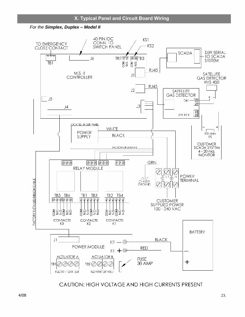
X. Typical Panel and Circuit Board Wiring ........ 23
A. For the Simplex, Duplex .............................. 23
B. For The Hexacon. .......................................... 24
C. For Relay Interface Module .......................... 25
XI. Notes .........................................................26-28
4/08
Table of Contents
A. General
The Halogen Valve Systems system controller and the Eclipse tm actuator are designed to be used with the standard cylinder and ton container valve approved for chlorine service by The Chlorine Institute. The Eclipse tm actuator is an automatic-closing, fail-safe valve closer that supplements the manual operation of these valves by providing for powered valve closure in case of an emergency. No modification of existing container valve or related hardware is required to install the system controller or the Eclipse tm actuator.
B. Warranty
Halogen Valve Systems emergency actuators are warranted to be free of manufacturing defects for a period of 3 years. Any defective components shall be replaced free of charge during the warranty period with the exception of the battery which has a one year limit. Damages due to negligence or other outside and environmental forces are excluded. See Warranty or Annual Certification Program document s for exclusions and extended warranty provisions.
C. Standard Equipment The Halogen emergency shutoff system consists of the following major components and accessories:
Major Components
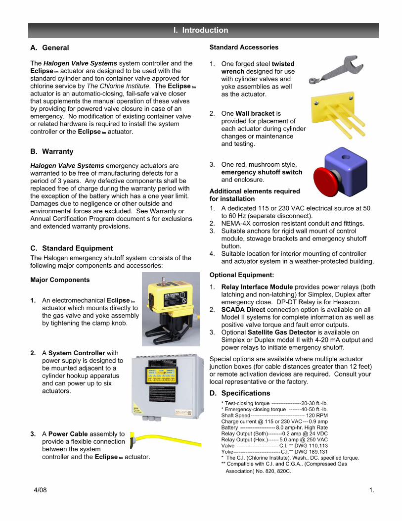
1. An electromechanical Eclipse tm actuator which mounts directly to the gas valve and yoke assembly by tightening the clamp knob.
2. A System Controller with power supply is designed to be mounted adjacent to a cylinder hookup apparatus and can power up to six actuators.
3. A Power Cable assembly to provide a flexible connection between the system controller and the Eclipse tm actuator.
Standard Accessories
1. One forged steel twisted wrench designed for use with cylinder valves and yoke assemblies as well as the actuator.
2. One Wall bracket is provided for placement of each actuator during cylinder changes or maintenance and testing.
3. One red, mushroom style, emergency shutoff switch and enclosure.
Additional elements required for installation 1. A dedicated 115 or 230 VAC electrical source at 50
to 60 Hz (separate disconnect). 2. NEMA-4X corrosion resistant conduit and fittings. 3. Suitable anchors for rigid wall mount of control
module, stowage brackets and emergency shutoff button.
4. Suitable location for interior mounting of controller and actuator system in a weather-protected building.
Optional Equipment:
1. Relay Interface Module provides power relays (both latching and non-latching) for Simplex, Duplex after emergency close. DP-DT Relay is for Hexacon.
2. SCADA Direct connection option is available on all Model II systems for complete information as well as positive valve torque and fault error outputs.
3. Optional Satellite Gas Detector is available on Simplex or Duplex model II with 4-20 mA output and power relays to initiate emergency shutoff.
Special options are available where multiple actuator junction boxes (for cable distances greater than 12 feet) or remote activation devices are required. Consult your local representative or the factory.
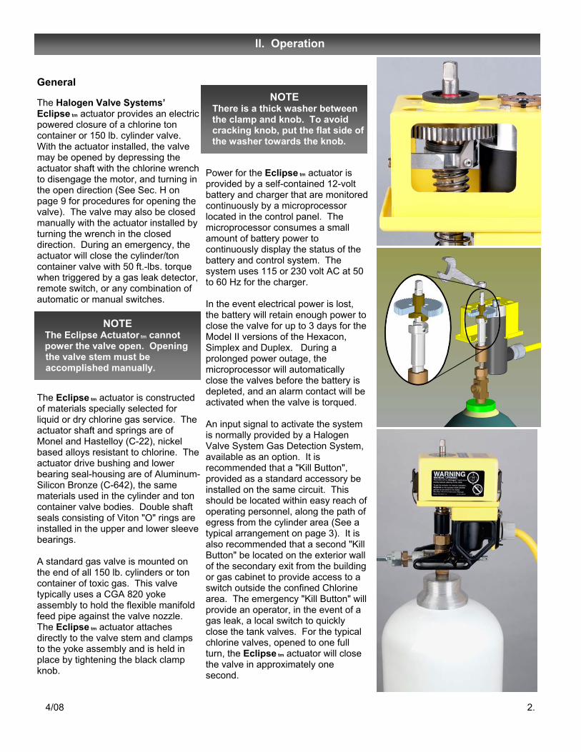
The Halogen Valve Systems’ Eclipse tm actuator provides an electric powered closure of a chlorine ton container or 150 lb. cylinder valve. With the actuator installed, the valve may be opened by depressing the actuator shaft with the chlorine wrench to disengage the motor, and turning in the open direction (See Sec. H on page 9 for procedures for opening the valve). The valve may also be closed manually with the actuator installed by turning the wrench in the closed direction. During an emergency, the actuator will close the cylinder/ton container valve with 50 ft.-lbs. torque when triggered by a gas leak detector, remote switch, or any combination of automatic or manual switches.
The Eclipse tm actuator is constructed of materials specially selected for liquid or dry chlorine gas service. The actuator shaft and springs are of Monel and Hastelloy (C-22), nickel based alloys resistant to chlorine. The actuator drive bushing and lower bearing seal-housing are of Aluminum-Silicon Bronze (C-642), the same materials used in the cylinder and ton container valve bodies. Double shaft seals consisting of Viton "O" rings are installed in the upper and lower sleeve bearings. A standard gas valve is mounted on the end of all 150 lb. cylinders or ton container of toxic gas. This valve typically uses a CGA 820 yoke assembly to hold the flexible manifold feed pipe against the valve nozzle. The Eclipse tm actuator attaches directly to the valve stem and clamps to the yoke assembly and is held in place by tightening the black clamp knob.
Power for the Eclipse tm actuator is provided by a self-contained 12-volt battery and charger that are monitored continuously by a microprocessor located in the control panel. The microprocessor consumes a small amount of battery power to continuously display the status of the battery and control system. The system uses 115 or 230 volt AC at 50 to 60 Hz for the charger. In the event electrical power is lost, the battery will retain enough power to close the valve for up to 3 days for the Model II versions of the Hexacon, Simplex and Duplex. During a prolonged power outage, the microprocessor will automatically close the valves before the battery is depleted, and an alarm contact will be activated when the valve is torqued. An input signal to activate the system is normally provided by a Halogen Valve System Gas Detection System, available as an option. It is recommended that a "Kill Button", provided as a standard accessory be installed on the same circuit. This should be located within easy reach of operating personnel, along the path of egress from the cylinder area (See a typical arrangement on page 3). It is also recommended that a second "Kill Button" be located on the exterior wall of the secondary exit from the building or gas cabinet to provide access to a switch outside the confined Chlorine area. The emergency "Kill Button" will provide an operator, in the event of a gas leak, a local switch to quickly close the tank valves. For the typical chlorine valves, opened to one full turn, the Eclipse tm actuator will close the valve in approximately one second.
ll. Operation
4/08 2.
NOTE The Eclipse Actuator tm cannot power the valve open. Opening
the valve stem must be accomplished manually.
NOTE There is a thick washer between the clamp and knob. To avoid cracking knob, put the flat side of the washer towards the knob.
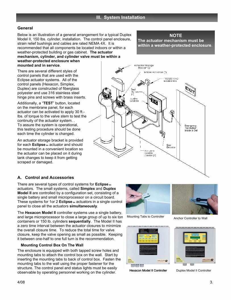
General Below is an illustration of a general arrangement for a typical Duplex Model II, 150 lbs. cylinder, installation. The control panel enclosure, strain relief bushings and cables are rated NEMA 4X. It is recommended that all components be located indoors or within a weather-protected building or gas cabinet. The actuator mechanism, cylinder, and cylinder valve must be within a weather-protected enclosure when mounted and in service. There are several different styles of control panels that are used with the Eclipse actuator systems. All of the control panels (Hexacon, Simplex, Duplex) are constructed of fiberglass polyester and use 316 stainless steel hinge pins and screws with brass inserts. Additionally, a “TEST” button, located on the membrane panel, for each actuator can be activated to apply 30 ft.-lbs. of torque to the valve stem to test the continuity of the actuator system. . To assure the system is operational, this testing procedure should be done each time the cylinder is changed.
An actuator storage bracket is provided for each Eclipse tm actuator and should be mounted in a convenient location so the actuator can be placed on it during tank changes to keep it from getting scraped or damaged.
lll. System Installation
4/08 3.
NOTE The actuator mechanism must be within a weather-protected enclosure.
A. Control and Accessories There are several types of control systems for Eclipse tm actuators. The small systems, called Simplex and Duplex Model II are controlled by a configuration set, consisting of a single battery and small microprocessor on a circuit board. These systems for 1or 2 Eclipse tm actuators in a single control panel to close all the actuators simultaneously.
The Hexacon Model II controller systems use a single battery, and large microprocessor to close a large group of up to six ton containers or 150 lb. cylinders sequentially. The Model II has a zero time interval between the actuator closures to minimize the overall closure time. To reduce the total time for valve closure, keep the valve opening as small as possible. Keeping it between one-half to one full turn is the recommendation. Mounting Control Box On The Wall The enclosure is equipped with both tapped screw holes and mounting tabs to attach the control box on the wall. Start by inserting the mounting tabs to back of control box. Fasten the mounting tabs to the wall using the proper fastener for the structure. The control panel and status lights must be easily observable by operating personnel working on the cylinder.
Mounting Tabs to Controller Anchor Controller to Wall
Hexacon Model II Controller
Duplex Model II Controller Hexacon Model II Controller
B. Wall Bracket Install wall bracket in location convenient to cylinder change. A wall mounted actuator stowage bracket is provided for temporary placement of the actuator when it is not installed on the cylinder. This should be mounted to a wall or structure convenient to the cylinder valve location and within the reach of the actuator cable.
The control system is mounted within a NEMA-4X enclosure rated for a corrosive chemical environment. The control panel should be rigidly mounted to a wall or other permanent structure so that the maximum distance to the actuator is 40 feet of cable length. The actuator should be convenient to the gas cylinder valve as well as the actuator stowage bracket.
Installation of the control panel should be performed by a qualified electrician in accordance with applicable electrical codes. It is recommended that 115 or 230 VAC power to the control panel be supplied from its own circuit breaker. Wiring should be through rigid PVC or flexible PVC coated conduit such as "Liquid-tite" and provide a NEMA-4X connections.
Connections and terminations should be made only in enclosures rated for the corrosive environment encountered in chlorine facilities (NEMA-4X). The control panel bulkhead fittings should be of the proper size and type to insure the gas-tight integrity of the enclosure is not broken at wire or conduit entrances. Daniel Woodhead "Max Loc" or similar fittings are preferred.
C. Actuator Cable Run all rough wiring using conduit and entry fittings that maintain gas tight integrity rating. (NEMA-4X). The actuator is shipped with a standard 12 foot electrical cable permanently attached to the actuator drive motor. This is the maximum length of this cable that may be used with the actuator. Do not attempt to add to the length of these cables or splice them in any way. Poor performance of the actuator will result. If longer cable lengths are necessary, consult the factory.
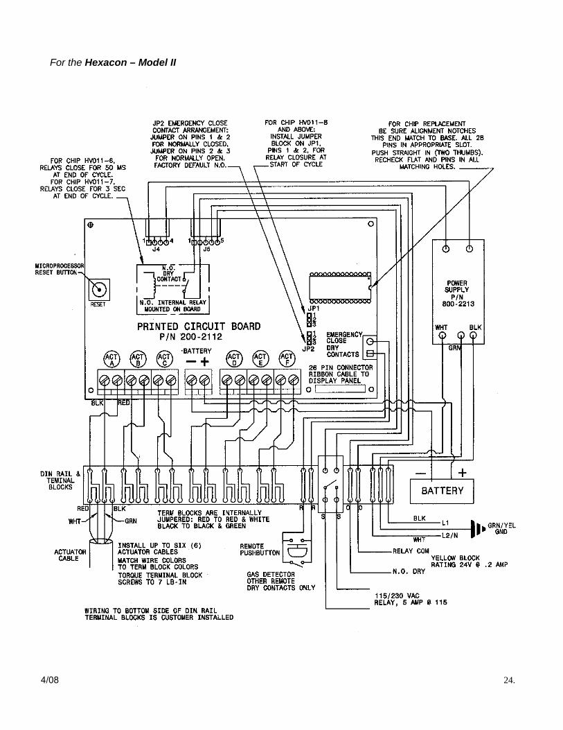
For the Hexacon – Model II Connect all actuators to the actuator control blocks inside the controller. Observe wire color coordination for each actuator block (i.e., white wire to white block, red wire to red block, etc.). Each actuator block is marked A, B, C, D, E, and F. The letters correspond to the test buttons on the membrane panel of the control box.
For the Simplex, Duplex – Model II
Connect actuator cables to the actuator control block inside the control unit. Verify that the actuator wire colors correspond with the wire colors from the controller and are connected accordingly.
Hexacon Model II Controller
Simplex and Duplex Model II Controller
Actuator stored in wall bracket
CAUTION Do not connect power to the control unit until instructed to do so. All other connections should be completed first. Connecting AC power to the improper rail block will damage the control unit.
4/08 4.
Eclipse Actuator wall bracket
Strain Relief Bushing
Remote Inputs Connect wires from remote kill button and/or remote gas sensor to the gray DIN rail terminal blocks labeled “R.” Use 24 AWG twisted and shielded wire (such as Belden 9501 or equivalent). Do not put shielded wire in conduit with other electric wiring. Note, the inputs can be configured for either normally open or normally closed contacts via a jumper setting, JP2, on the controller circuit board. The controller default setting is normally open. This setting will cause all attached valves to actuate during an EMERGENCY CLOSE situation, if any contact switch is closed, thereby completing the circuit. Remember to verify that the remote sensor relays are configured to be consistent with the JP2 setting on the controller circuit board. Low Level Output Relay The two yellow terminal blocks on the right side of the DIN rail, each labeled with an “O,” are low-level relays which are normally open. Relay closure depends upon the setting of a jumper, JP1, on the controller board. When JP1 is closed (pin 1 & 2 connected), the relay will close immediately upon detection of an EMERGENCY CLOSE command and will stay closed for a minimum of 3 seconds. The relay will close again for a minimum of 3 seconds only if during an EMERGENCY CLOSE command, all connected valves close and completely torque. If the jumper is left open (i.e., pin 2 & 3 connected or jumper removed), the relay will close for 3 seconds only if upon an EMERGENCY CLOSE command, all connected valves close and completely torque. Note, the controller requires that the reset button be pressed after changing the JP1 setting for that new change to take effect. This relay output has a maximum rating of 200 mA and 24 volts. High Voltage Safety Relay The tan DIN rail terminal block labeled “S1" and “S2" is a 115 / 230 volt relay rated at 5 amps. The relay closure depends upon the JP1 setting on the controller board. When the JP1 is closed (pin 1 & 2 connected), the relay will close immediately upon detection of a EMERGENCY CLOSE command and the contact will remain for a minimum of 3 seconds. The relay will close again for a minimum of 3 seconds only if during an EMERGENCY CLOSE command, all connected valves close and completely torque. If JP1 is left open (i.e., pin 2 & 3 connected or jumper removed), the relay will close for 3 seconds only if upon an EMERGENCY CLOSE command, all connected valves close and torque completely. Note, the controller requires the reset button to be pressed after changing the JP1 for that new change to take effect.
4/08 5.
CAUTION Do not connect power to the control unit until instructed to do so. All other connections should be completed first. Connecting AC power to the improper DIN rail block will damage the control unit.
D. Input/Output Wiring
For the Hexacon - Model II
Remote Input
Attach the wires from any remote gas detectors, remote kill buttons, PLC or SCADA systems and other remote contacts to terminal block “TB1”. Use 24 AWG twisted and shielded wire (such as Belden 9501 or equivalent) for these connections. Do not put shielded wire in the conduit with other electric wiring. Connect the shield to the terminal receptacle on TB1 marked “Shield”. The TB1 terminal block can be configured normally open or normally closed via the “membrane panel” setting located on the front controller panel. The terminal block’s default setting is normally open. This normally open setting will, when activated, cause all attached valves to close when any contact on the circuit is closed. Before connecting power, verify that all remote sensor relays are configured to be consistent with the terminal block configuration setting.
Relay Output
The terminal blocks “TB2” (Actuator A) and “TB3” (Actuator B) will provide an output signal (closed contact) through contacts which are normally open. The output signals are activated independently when the Eclipse actuator to which it is connected closes and torques the valve. The relay will stay closed for a minimum of 3 seconds. This output signal, rated at 200 mA (max) at 24 volts can be used to communicate with an PLC device. If a greater voltage or current and/or a latching function is needed, the Relay Interface Module (optional) will be required.
Relay Interface Module (Optional)
The Relay Interface Module will provide 250 VAC - 5 amp connections in addition to programmable selections. When the Relay Interface Module is attached to the main circuit board using the J3 connector the programming for relays K1, K2 and K3 (page 25) is then made available. These three relays can be programmed to indicate several functional and diagnostic conditions or change from momentary to a latching relays. Relay KS1, terminal block TB2 and relay KS2, terminal block TB3 (shown above) can also be programmed in the same way when in this optional configuration.
4/08 6.
CAUTION Do not connect power to the control unit until instructed to do so. All other connections should be completed first. Connecting AC power to the improper terminal block will damage the control unit.
For the Simplex, Duplex – Model II
CAUTION Do not connect unauthorized power relays or other devices inside the system control box. This will prevent magnetic pulse damage to the computer as well as void the Warranty.
Remote Input Terminal Block - TB1
Relay Output Terminal Blocks - TB2 (Actuator A) & TB3 (Actuator B)
Relay Interface Module
AC Wiring Connections. After the control panel is mounted and all I/O connections are made, connect the 115/230 VAC power leads to the Black (Line 1, high side), White (Line 2, low side) and Green/Yellow (ground) terminal blocks on the right side of the DIN rail. Conduit and fittings should be of the type to maintain the gas and liquid tight integrity of the control enclosure. Before applying AC power to the circuit, connect the battery as shown in section G. Battery Installation, page 8.
E. 115 or 230 VAC Wiring
During an emergency close (initiated with ”Remote Input” circuit) the Hexacon closes the actuators sequentially. That means that the actuators close one at a time with a delay in between each for recovery. The actuator turns at about two turns per second. Recovery time for the Hexacon Model II is virtually immediate. Total system closure time for either system will depend on the number of actuators, the degree or amount that each valve is opened.
AC Wiring Connection. After the control panel is mounted and all I/O connections are made, connect the 115/230 VAC power leads to the terminal blocks marked and shown as “GRN” (ground)., “BLK” (Line 1, high side), and “WHT” (Line 2, low side). All conduit and fittings should be rated NEMA-4X or a type that maintains the gas and liquid tight integrity of the control enclosure. Before applying AC power to the circuit, connect the battery as shown in section G. Battery Installation, page 8.
F. Emergency Close Circuit
4/08 7.
CAUTION Verify that AC power is turned off before connecting power leads to the control unit. Do not apply AC power to control system until battery is connected and installation is complete.
For the Simplex, Duplex – Model II
For the Simplex, Duplex – Model II
During an emergency close (initiated with remote contact circuits) the Simplex, Duplex will close their actuators all at the same time, when the emergency contact circuit is initiated. Total system closure time depends only on the degree or amount to which each valve is opened. The actuator turns at about two turns per second.
For the Hexacon – Model II
For the Hexacon – Model II
WHT GRN BLK
G. Battery Installation
Connect the Positive terminal of the battery to the Red controller wire and slide the battery into the bracket. Install the battery cross bar and tighten the captive screws. Connect the Negative terminal of the battery to the Black controller wire. The “Armed/Ready” light should flash green, after the battery is connected. Now apply 115 or 230 VAC power to the control system. The “CHARGE OK” light should now illuminate green. Press the circuit board “RESET” button to insure initiation of the control program. This is always required whenever a battery is newly installed or becomes disconnected for any reason. Note: On Model II only, holding down “Test F” button on the front panel for six (6) seconds (until all lights flash) will reset the computer. This function does not work if a low battery is the problem.
WARNING If the polarity of the battery connection is accidentally reversed, the circuit board will be damaged. Return to factory for repair.
If the red “BATTERY LOW” light illuminates after 115/230 VAC power is applied, the battery may have been discharged during storage or transit. It should go out after a few minutes. Do not proceed with the remainder of the installation until the “BATTERY LOW” light is off. See the troubleshooting section of this manual for battery test or replacement procedures. If the “FAULT ERROR” light is blinking on the Hexacon - Model II, the light will blink the number of times shown in the Model II column on the table below.
Mounting battery
Securing battery
Replace Battery Annually.
4/08 8.
For the Hexacon – Model II
Model II Error Light Explanation 1 Battery is disconnected 2 Battery voltage is less than 12.4 DC volts 3 Battery voltage is greater than 15.0 DC volts 4 Charger voltage is out or less than 13.9 DC volts 5 Charger voltage is greater than 16.3 volts
6 The 30-amp fuse is open or defective 7 Computer supply is out of the range of 4.6 to 5.3 volts 8 An Eclipse Actuator shorted during the last activation 9 One actuator did not torque during the last activation
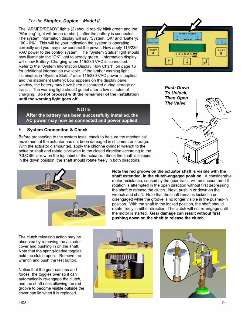
The “ARMED/READY” lights (2) should rapidly blink green and the “Warning” light will be on (amber) , after the battery is connected. The system information display will say “System: OK” and “Battery: 100 - 0%”. This will be your indication the system is operating correctly and you may now connect the power. Now apply 115/230 VAC power to the control system. The “System Status” light should now illuminate the “OK” light to steady green. Information display will show Battery: Charging when 115/230 VAC is connected. Refer to the “System Information Display Flow Chart”, on page 16 for additional information available. If the amber warning light illuminates in “System Status” after 115/230 VAC power is applied and the statement Battery: Low appears on the display panel window, the battery may have been discharged during storage or transit. The warning light should go out after a few minutes of charging. Do not proceed with the remainder of the installation until the warning light goes off.
H. System Connection & Check Before proceeding to the system tests, check to be sure the mechanical movement of the actuator has not been damaged in shipment or storage. With the actuator dismounted, apply the chlorine cylinder wrench to the actuator shaft and rotate clockwise to the closed direction according to the "CLOSE" arrow on the top label of the actuator. Since the shaft is shipped in the down position, the shaft should rotate freely in both directions.
Note the red groove on the actuator shaft is visible with the shaft extended, in the clutch-engaged position. A considerable motor resistance, caused by the gear train, will be encountered if rotation is attempted in the open direction without first depressing the shaft to release the clutch. Next, push in or down on the wrench and shaft. Note that the shaft remains locked in or disengaged while the groove is no longer visible in the pushed-in position. With the shaft in the locked position, the shaft should rotate freely in either direction. The clutch will not re-engage until the motor is started. Gear damage can result without first pushing down on the shaft to release the clutch.
The clutch releasing action may be observed by removing the actuator cover and pushing in on the shaft. Note that the spring-loaded toggles hold the clutch open. Remove the wrench and push the test button. Notice that the gear catches and forces the toggles over so it can automatically re-engage the clutch, and the shaft rises allowing the red groove to become visible outside the cover can lid when it is replaced.
4/08 9.
For the Simplex, Duplex – Model II
NOTE After the battery has been successfully installed, the AC power may now be connected and power applied.
Push Down To Unlock, Then Open The Valve
The electrical system may be checked for proper polarity and status indication by test running the actuator motor while sitting on the wall bracket. Initiate the test sequence by pressing the “Test” button on the membrane panel. Observe that the actuator shaft rotates in the clockwise direction as viewed from above. The actuator motor should run for about 3 seconds and then shut off automatically. The actuator cables and controls are of the proper polarity when the motor drives the shaft in the clockwise direction as seen from above.
lV. Mounting to a Cylinder Valve
Follow these procedures:
1 Make sure all piping connections are in accordance with The Chlorine Manual or local procedures. The yoke (Part No. 5151.00) and CGA 820 connection are the standard connection adapters to the container valve outlet. Always install a fresh gasket between the valve face and the CGA 820 connection.
2 Tightening the yoke bolt will compress the gasket and secure the yoke rigidly to the valve thereby coupling the valve outlet flange to the process tubing or pipe using the CGA 820 Connection.
3 The actuator mounting clamp is designed to straddle and grasp the yoke firmly.
4 Align the actuator shaft and bronze drive bushing with the valve stem. With the actuator clamps loose and parallel to the sidebars of the yoke, push while rotating the shaft to align the bushing and stem flats.
5 The spring-loaded bronze drive bushing at the base of the actuator shaft should fully engage the wrench flats on the valve stem.
6 Tighten the mounting clamp while rocking the actuator slightly back and forth. This will assist in aligning the actuator with the sides of the yoke, and the actuator shaft will be concentric with the valve stem. Note, tighten the clamp to only finger-tight with the clamp knob, flat side of the washer towards the knob.
7 Check for proper alignment of the actuator and the valve stem by pushing in (or down) about ⅜ inch on the actuator shaft and releasing with the wrench applied to the shaft.
8 About 6 to 8 pounds of force is required to compress the shaft spring. When released, the shaft should immediately snap back up to the intermediate position. The clutch should now be disengaged and the red groove should not be visible.
9 Shaft movement, in and out, should be smooth and free of any binding. If not, loosen the clamp knob slightly and adjust the alignment of the actuator then re-tighten the clamp knob.
10 It may take some practice to gain a feel for mounting the actuator so that the shaft is free to slide properly. To gain a feel for what the shaft movement should be, test the movement of the shaft while the actuator is dismounted or attached to the wall bracket.
WARNING The yoke must be tightened firmly to the valve to insure that the torque reaction of the actuator closing does not unseat the lead gasket.
4/08 10.
WARNING Binding or intermittent movement of the sliding action of the shaft, in and out, may reduce the torque applied to the valve during closing.
4/08 11.
The Eclipse Actuator tm may be integrated with some valve mounted vacuum regulators to make a convenient, single unit for easier mounting. Regulators similar to those manufactured by Fischer-Porter, Capital Controls, and Regal require an adapter that is specially designed for that particular brand of vacuum regulator. The manufacturer and model must be specified when ordering the adapter. The adapter replaces the vacuum regulator yoke cross bar as shown in Fig. 1. The adapter also takes the place of the Halogen yoke clamp assembly also shown in Fig. 1.
Vacuum regulators manufactured by the Wallace & Tiernan Company employ a forged steel yoke. These vacuum regulators do not require an adapter. The yoke clamp assembly of the actuator will mount directly to this yoke as described in Section IV.
The Halogen actuator may be ordered with the vacuum regulator adapter already installed or it may be retrofitted in the field using the following procedure, shown in Fig. 1.
1. Remove the regulator clamp screw (D) from the cross bar and reinstall the screw in the center threaded hole in the V-R dir mount adapter (F) part number 6302.00.
2. Remove the two nuts (C) from the vacuum regulator threaded crossbar (A) and set crossbar (A) aside.
3. Install the adapter (F) on the threaded clamp rods. Be sure to leave the sliding follower (B) on the rods between the adapter and the inlet to the regulator. Tighten the nuts (C) securely.
4. Remove the two locking pins (E) from the actuator. The actuator yoke clamping brackets, in Fig. 1, may then be removed with the clamp knob, spring and screw assembly attached.
5. Place the actuator frame atop the adapter with the pinholes in approximate alignment with the corresponding holes on the adapter. Reinstall the locking pin (E) to complete the attachment of the actuator to the vacuum regulator mounting adapter.
The vacuum regulator and the Eclipse Actuator tm may now be mounted to the valve as a single unit. The mounting technique is similar to installing the regulator alone except that the bronze drive socket of the actuator must now engage the wrench flats on the valve stem.
B. Auxiliary Valve—Regulator Mounting The standard Eclipse Actuator tm clamp will mount to an “Auxiliary Valve Adapter” as seen in Fig 2. This provides a second chlorine valve to attach the vacuum regulator. This configuration may be used to mount the actuator in conjunction with virtually any make of vacuum regulator. The Auxiliary Valve Adapter is Halogen Valve Systems’ part number 2202.00. This auxiliary valve must be adjusted slightly so the discharge of the auxiliary valve is turned 90o to the lead seal compression flange of the yoke as shown in Fig. 2 to assure the proper clearance.
A. Vacuum Regulator Direct Mounting
Fig. 1
Fig. 2
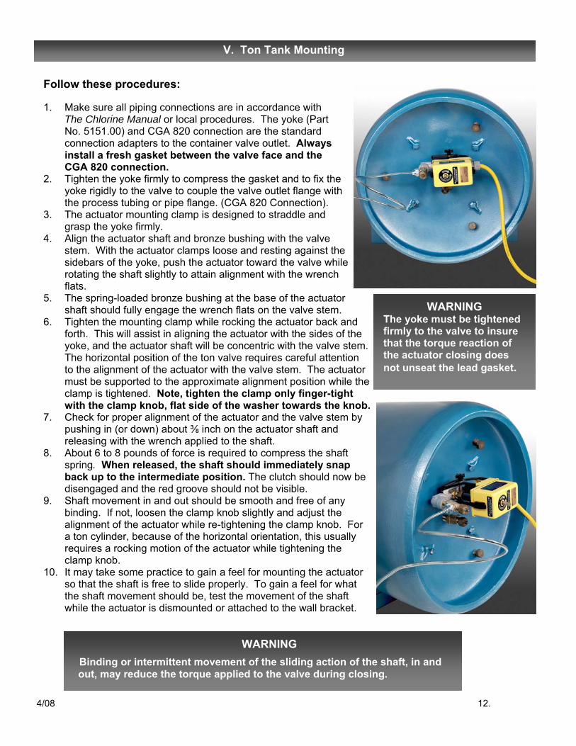
Follow these procedures: 1. Make sure all piping connections are in accordance with The Chlorine Manual or local procedures. The yoke (Part No. 5151.00) and CGA 820 connection are the standard
connection adapters to the container valve outlet. Always install a fresh gasket between the valve face and the
CGA 820 connection. 2. Tighten the yoke firmly to compress the gasket and to fix the
yoke rigidly to the valve to couple the valve outlet flange with the process tubing or pipe flange. (CGA 820 Connection).
3. The actuator mounting clamp is designed to straddle and grasp the yoke firmly.
4. Align the actuator shaft and bronze bushing with the valve stem. With the actuator clamps loose and resting against the sidebars of the yoke, push the actuator toward the valve while rotating the shaft slightly to attain alignment with the wrench flats.
5. The spring-loaded bronze bushing at the base of the actuator shaft should fully engage the wrench flats on the valve stem.
6. Tighten the mounting clamp while rocking the actuator back and forth. This will assist in aligning the actuator with the sides of the yoke, and the actuator shaft will be concentric with the valve stem. The horizontal position of the ton valve requires careful attention to the alignment of the actuator with the valve stem. The actuator must be supported to the approximate alignment position while the clamp is tightened. Note, tighten the clamp only finger-tight with the clamp knob, flat side of the washer towards the knob.
7. Check for proper alignment of the actuator and the valve stem by pushing in (or down) about ⅜ inch on the actuator shaft and releasing with the wrench applied to the shaft.
8. About 6 to 8 pounds of force is required to compress the shaft spring. When released, the shaft should immediately snap back up to the intermediate position. The clutch should now be disengaged and the red groove should not be visible.
9. Shaft movement in and out should be smooth and free of any binding. If not, loosen the clamp knob slightly and adjust the alignment of the actuator while re-tightening the clamp knob. For a ton cylinder, because of the horizontal orientation, this usually requires a rocking motion of the actuator while tightening the clamp knob.
10. It may take some practice to gain a feel for mounting the actuator so that the shaft is free to slide properly. To gain a feel for what the shaft movement should be, test the movement of the shaft while the actuator is dismounted or attached to the wall bracket.
V. Ton Tank Mounting
WARNING Binding or intermittent movement of the sliding action of the shaft, in and out, may reduce the torque applied to the valve during closing.
4/08 12.
WARNING The yoke must be tightened firmly to the valve to insure that the torque reaction of the actuator closing does not unseat the lead gasket.
A. Ton Tank Vacuum Regulator Mounting
Vacuum regulators (VR) are designed to mount directly to the ton container valve and vary widely in weight and configuration from one manufacturer to another. All of the vacuum regulators can be converted to header or wall mounting as shown in Fig. 4 to reduce the weight on the valve. This header or wall mounted arrangement is the preferred method for use with the Halogen Valve Actuator. Some makes and models of vacuum regulators may be mounted directly to the ton container valve in conjunction with the actuator as shown in Fig. 3. The auxiliary valve and yoke assembly, Part No. 2202.00, is required to provide sufficient clearance for the actuator. This arrangement requires that both the vacuum regulator and valve actuator be removed and re-installed with each container change. In some cases, this method will require two make-break connections and gaskets as compared to the single make-break and actuator connection shown in Fig. 4. Access to the vacuum regulator and the actuator is constrained by their close proximity. Some vacuum regulators are too heavy to be mounted as shown in Fig. 3. Contact your local Halogen Valve Systems rep or consult the factory.
B. Other Cylinder & Ton Tank Connections
The clamp mounting system for the Halogen valve actuator is designed to mate with the two approved (CGA and Chlorine Institute) yoke connection devices. Adapters are available to direct mount with most common cylinder valve mounted regulators that do not employ these standard yoke connections. The auxiliary valve adapter (Part No. 2202.00) may be combined to mount the actuator with almost any connection scheme. Special adapters can be provided for unusual regulator or tubing connection devices. Consult the factory for engineering assistance.
The configuration shown in Fig. 4 has several advantages. The V-R becomes semi-permanently installed on the header and need not be changed with each container change. Only one make-break connection is required at the yoke connection during changeover. Container changeover is simplified, leak checks and troubleshooting are easier and the operator has convenient access to all connections. The changeover is less complex and there is less opportunity for error. Field experience has shown that operating personnel much prefer this arrangement. The only disadvantage to the arrangement of Fig. 4 is that the pigtail is pressurized and cannot be isolated by the shutdown feature of the V-R. The amount of chlorine gas contained in the pigtail connection at normal temperature and pressure is very small, about 8 grams or 1/3rd ounce. This small exposure, should it escape, is offset by the advantage of having automatic shut-off at the container valve.
4/08 13.
Fig. 4
Fig. 3
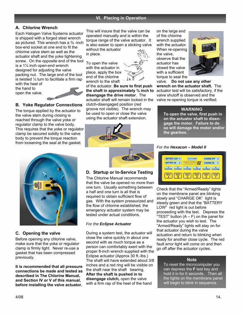
A. Chlorine Wrench Each Halogen Valve Systems actuator is shipped with a forged steel wrench as pictured. This wrench has a ⅜ -inch box-end socket at one end to fit the chlorine valve stem as well as the actuator shaft and the yoke tightening screw. On the opposite end of the tool is a 1¼ inch open-end wrench designed for adjusting the valve packing nut. The large end of the tool is twisted ¼ turn to facilitate a firm rap with the heel of the hand to open the valve.
B. Yoke Regulator Connections The torque applied by the actuator to the valve stem during closing is reached through the valve yoke or regulator clamp to the valve body. This requires that the yoke or regulator clamp be secured solidly to the valve body to prevent the torque reaction from loosening the seal at the gasket.
C. Opening the valve Before opening any chlorine valve, make sure that the yoke or regulator clamp is firmly tight. Never re-use a gasket that has been compressed previously. It is recommended that all pressure connections be made and tested as described in The Chlorine Manual, and Section IV or V of this manual, before installing the valve actuator.
This will insure that the valve can be operated manually and is within the torque range of the valve actuator. It is also easier to open a sticking valve without the actuator in place. To open the valve with the actuator in place, apply the box end of the chlorine wrench to the shaft of the actuator. Be sure to first push the shaft in approximately ⅜ inch to disengage the drive motor. The actuator shaft will remain locked in the clutch-disengaged position (red groove not visible). The wrench may be used to open or close the valve using the actuator shaft extension.
D. Startup or In-Service Testing The Chlorine Manual recommends that the valve be opened no more than one turn. Usually something between a half and one turn is all that is required to obtain sufficient flow of gas. With the system pressurized and the flow of chlorine established, the emergency actuator system may be tested under actual conditions. For the Eclipse Actuator During a system test, the actuator will close the valve quickly in about one second with as much torque as a person can comfortably exert with the proper 8-inch wrench supplied with the Eclipse actuator (Approx 30 ft.-lbs.) The shaft will have extended about 3/8 inches and a red ring will be visible on the shaft near the shaft bearing. After the shaft is pushed in to disengage clutch, open the valve with a firm rap of the heel of the hand
on the large end of the chlorine wrench supplied with the actuator. When re-opening the valve, observe that the actuator has closed the valve with a sufficient torque to seal the valve. Do not use any other wrench on the actuator shaft. The actuator test will be satisfactory, if the valve shutoff is observed and the valve re-opening torque is verified.
For the Hexacon – Model II
Check that the “Armed/Ready” lights on the membrane panel are blinking slowly and “CHARGE OK” light is steady green and that the “BATTERY LOW” red light is out before proceeding with the test. Depress the “TEST” button (A – F) on the panel for the actuator you wish to test. The “Armed/Ready” lights will stay on for that actuator during the valve actuation and return to blinking when ready for another close cycle. The red fault error light will come on and then go off after the actuator cycles.
WARNING To open the valve, first push in on the actuator shaft to disen-gage the motor. Failure to do so will damage the motor and/or the gearbox.
Vl. Placing in Operation
4/08 14.
Note To reset the microcomputer you can depress the F test key and hold it in for 6 seconds. Then all the lights on the membrane panel will begin to blink in sequence.
4/08 15.
For the Simplex, Duplex – Model II 1. Check that the Armed/Ready light
on the membrane panel is blinking , the System Status - OK light (green) is on and “System: OK” and “Battery: Charging” is displayed in the information window before proceeding with the test. Depress the “TEST” button on the front of the controller for the actuator you wish to test. The Eclipse actuator will activate and close the cylinder valve with a torque of 30 foot-pounds. The green light above the test button pushed will go out for 10 seconds then return to blinking when ready for another close cycle.
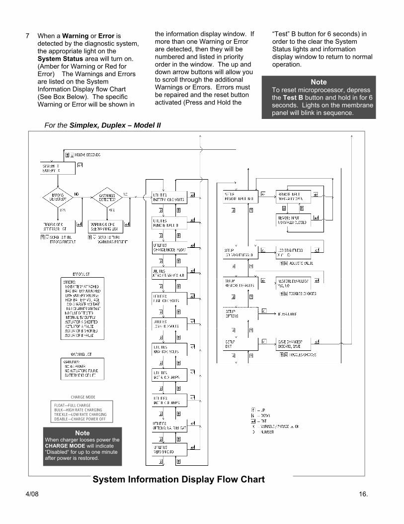
2 The System Information Display Flow Chart shown on page 16 contains all of the information necessary to observe and complete the final instrument settings for the microprocessor. Using the arrow buttons you can move up or down and between the Utilities and Setup sections.
3 The arrow buttons, shown above, are for controlling the up, down and the enter functions to move around and display information within the computer shown in the Flow Chart from the membrane panel. These buttons can be used to observe and change the internal settings of the system’s computer. The words shown in the boxes in the Flow Chart on page 16 are the same information that will be shown in the display window on the membrane panel.
Only the X’s will be replaced with a word or letters to provide information for the item selected. The 0.0’s would have a number or numbers depicted in their place.
4 The Utilities section of the Flow Chart depicts the unit settings for specific equipment and for other instruments. This section will depict system volts or amps to help provide diagnostic information. For Example, note the start box on the Flow Chart, the display window will show “System: OK” and “Battery; Charging”. If you want to know the actual charger circuit voltage, you simply press the “Enter” arrow button once and you will go to the first Utilities box showing, “Battery: 00.0 Volts” (See Flow Chart). While the battery is charging, this box will show the charger voltage. If you disconnect the 115/230 VAC, it will then read the actual battery voltage in that same display box. To move down or up the Flow Chart to other Utilities items, use the “Down” arrow or “Up” arrow buttons. To get back to the start box simply press the “Enter” arrow button.
5 The Setup section of the Flow Chart allows the operator to set or change the parameters of the specific items connected or options available to the control system. For example, at the start box on the Flow Chart, the display window shows “System: OK” and “Battery: Charging”. If you want to set the “Remote Input” to
Normally Closed or N.C., press and hold both the up and down buttons for 6 seconds and you will move to the first Setup box showing, “Remote Input: N.O.” (See Flow Chart). This is the Default Factory Setting. To change this setting to “Normally Closed”, simply press the “Enter” button to move to the “Normally; Open” box and then press the down arrow to move to the “Normally: Closed” box. Pressing the “Enter” Button will then select the N.C. setting. After obtaining the desired setting, and to return to the starting System box, simply move down to the Setup “Exit” box using the arrow keys and then press the “Enter” button.
6 If additional system Options are made available, then the box with the dotted line on the System Information Display Flow Chart would be the area where those boxes will appear. If more than one Option is made available, then several boxes will appear in this area of the Flow Chart. Documents shipped with the Options will explain their setup boxes and show how to move within the Flow Chart. Options will activate with the desired selections when and only if they are connected to the system. After the Setup is complete use the arrow button to get to the “Exit” box and then press the “Enter” button to return to the starting System box as shown on the flow chart.
Control Arrow Buttons
Note At startup or with a new battery check and set all of the system’s instrument settings. The System Information Display is designed to be used for this purpose.
Information Display
4/08 16.
For the Simplex, Duplex – Model II
7 When a Warning or Error is detected by the diagnostic system, the appropriate light on the System Status area will turn on. (Amber for Warning or Red for Error) The Warnings and Errors are listed on the System Information Display flow Chart (See Box Below). The specific Warning or Error will be shown in
the information display window. If more than one Warning or Error are detected, then they will be numbered and listed in priority order in the window. The up and down arrow buttons will allow you to scroll through the additional Warnings or Errors. Errors must be repaired and the reset button activated (Press and Hold the
“Test” B button for 6 seconds) in order to the clear the System Status lights and information display window to return to normal operation.
Note To reset microprocessor, depress the Test B button and hold in for 6 seconds. Lights on the membrane panel will blink in sequence.
System Information Display Flow Chart
Note When charger looses power the CHARGE MODE will indicate “Disabled“ for up to one minute after power is restored.
FLOAT—FULL CHARGE BULK—HIGH RATE CHARGING TRICKLE—LOW RATE CHARGING DISABLE—CHARGE POWER OFF
CHARGE MODE
4/08 17.
E. Corroded Valves Cylinder or ton containers left in dispensing service for long periods may develop corrosion or fouling of the valve body, packing, packing nut, and stem. This can substantially increase the amount of torque required to close the valve. In severe cases, the increase in the torque required could exceed the capacity of the actuator to close the valve. To reduce the potential for fouling, implement the following policies and procedures:
1. Test cycle the actuator system at least once per week. After each test, check yoke screw and tighten if required, up to one-eighth turn.
2. Specify that the chlorine supplier provide only cylinder or ton containers equipped with Chlorine Institute approved Teflon packing. This greatly reduces friction between the packing and stem. In the past, graphite-impregnated, split packing rings were the only approved packing system for cylinder or ton container valves. These require greater gland-nut tightness to seal, resulting in higher friction between the valve stem and packing. Friction is increased even more when the stem is corroded or fouled. The solid, non-split Teflon packing seals better, with less gland pressure and requires less force to open or close even when the stem is corroded. New seal kits are available for suppliers to convert existing valves to the new
Teflon packing at nominal cost. 3. Wet chlorine is the primary cause
of corrosion of the internal components of these valves. This may be due to poor quality control during the refilling of containers by the supplier. Additionally, moisture and/or other contaminants may not be fully evacuated from the chlorine container before refilling. In addition, moisture can enter the valve and cylinder through "suck-back" from the dispensing piping or atmosphere. This problem is the result of temperature changes or other design deficiencies in filling.
4. Consult with your supplier concerning refilling equipment and techniques as well as valve reconditioning and repackaging. Detailed procedures are covered in the Chlorine Institute (C.I.) Pamphlet # 17, Cylinder and Ton Container Procedure for Chlorine Packing, to insure high quality, dry chlorine and contaminant free valves that turn freely and easily (less than 10 ft-lb. of torque).
Consider the installation of equipment that dispenses chlorine gas under a vacuum. This can eliminate "suck-back" and the intrusion of atmospheric moisture. Your Halogen Valve Systems representative can provide information on devices engineered to dispense chlorine while precluding the introduction of contaminants.
F. Battery Characteristics
The test sequence, In-Service Testing, described in section D on page 14, should be performed each time that an empty cylinder is replaced with a full cylinder. For containers in extended service, the test should be performed at least once per month, preferably once a week.
The battery capacity is not appreciably affected by one or even several test cycles of the actuator when normal charging power is available.
If a gas sensor detects chlorine gas and automatically shuts the chlorine valve, make sure that the room is completely clear of chlorine gas before resetting the Halogen Valve automatic shut off system. Otherwise the gas sensor will detect the residual chlorine gas in the room and shut the system down again as soon as it is turned on. This is also true when changing ton cylinder containers. A small amount of chlorine gas may leak out of a pig-tail which may set off a gas sensor. A time delay relay may, after consulting the factory, be installed in the controller to allow time to completely air out the room.
Sensor Testing
The testing or calibration of sensor or remote inputs to the controller may be checked by the following procedure. This procedure also provides a check of the electrical continuity of the entire system including the sensor wiring.
1. Disconnect the actuator from the valve and place the actuator in the wall mounting bracket with the cable connected to the controller.
2. Expose the sensor to a calibration gas or otherwise activate the control input to the control module.
3. The actuator should run freely for about 2½ seconds indicating that the control unit received the signal.
Note, this procedure is similar to Functional Testing outlined previously, except that the triggering signal originates with the sensor rather than the Test button and the actuator is not connected to the cylinder valve. This procedure may be repeated, at 15 -second intervals, for numerous sensor calibrations without the necessity of re-opening the cylinder valve for each cycle. Additionally, the battery will not be depleted since there is no load on the drive motor.
WARNING If the valve cannot be readily operated both manually and by the actuator, the cylinder should not be placed in service under any circumstances. It should be returned to the supplier.
WARNING Torque transferred through the yoke to the lead washer during actuator testing can cause a leak. Retighten yoke after each test if required, up to one-eighth turn.
Vll. Gas Sensor
NOTE If the Simplex or Duplex “System Status” red light comes on and the “Low Battery voltage” displays, replace the battery right away. Use only factory certified battery.
4/08 18.
A. Battery Information 1. Replacement
Expected voltage life of this battery is 2 to 3 years under normal conditions. However, it is necessary to replace the battery annually, with a factory battery, to insure system warranty and reliability of torque application. The amperage of the battery will rapidly degrade after one year’s use, reducing the system’s torque applied.
2. Storage
Spare batteries, while not recommended, have an approximate six (6) months shelf life, if stored in a cool dry place. Periodic recharging is necessary with a regular service rotation to assure the shelf life of the battery.
WARNING If the ”BATTERY LOW” light remains illuminated for the Hexacon or if the Simplex or Duplex “System Status“ error light (red) illuminates the actuator may not operate even with charge power connected. If the battery is below 12.1 VDC, it may not recover regardless of charging time and must be replaced.
4. Changing Battery a) Disconnect the 115 or 230 VAC power at breaker box. b) Open control panel door and disconnect the black battery lead first. c) Loosen the two screws on the battery cross bar and remove bar. d) Pull the battery out about half way. Disconnect the red battery lead
and then remove the battery. e) Place the new battery halfway into the bracket, with the battery
terminals on the left. The positive terminal should be within easy reach of the red battery lead. Connect the red lead to the positive terminal, then slide the battery fully into the bracket.
f) Re-install the battery cross bar and tighten the two screws. g) Connect the black lead to the negative terminal of the battery. (The
“Armed/Ready” light should now illuminate and begin blinking.) h) Re-connect the 115 / 230 VAC power before resetting the system. i) Push correct “Test” button on membrane panel for 6 seconds to reset.
3. Operating Characteristics For the Hexacon – Model II
The “BATTERY LOW” light illuminates when the microprocessor has detected a voltage of less than 12.4 VDC across the battery. Note, on the Hexacon Model II the “BATTERY LOW” will illuminate at 12.6 and the “BATTERY OK” light will remain illuminated until the voltage drops below 12.4 VDC at which time the “OK” light will go out. The Eclipse actuator system will begin the close sequence when the battery voltage falls below 12.1 VDC.
For the Simplex, Duplex – Model II
The “System Status” warning light (amber) will come on when the microprocessor has detected a voltage of less than 12.6 VDC across the battery. During activation or system test, the warning light may flash intermittently. This is due to the high (50 to 75 amps) current draw of the motor during the closure and seating of the valve. As long as the warning light returns to off, the battery has sufficient charge.
Note: For all Shutoff systems, a fully charged battery has the capacity to power the actuator through ten cycles, under load, in a five-minute period. Thereafter, allow ten minutes for cooling and recharging. Dis-charging below approx. 9.0 volts can damage the battery and prevent the battery from being recharged.
CAUTION The actual battery voltage can only be checked when under a load.
Vlll. Maintenance
4/08 19.
B. Lubrication for the Eclipse actuator
Once a year or if shaft is sticking, clean and lubricate, with a small amount of lubricant, the mating surfaces of the shaft at the entrance to both top and bottom bearings and the drive bushing. Do not clean with any solvents or apply lubrication to any other parts such as springs or latches. This additional lubricant might cause sticking or misalignment and possibly prevent the gears from engaging. Use Lubriplate # 930-AA Grease or Dow Corning # 111 Silicone valve lubricant sparingly. Return to factory for our Annual Certification Program when the warranty period is over, to assure compliance and extended life.
C. Cables and connections
Check the continuity of the sensor input connections. Clean and tighten if necessary. When performing periodic sensor calibrations as called for by the sensor manufacturer, perform sensor test described in Sec. VII to verify the entire system.
D. Microprocessor Circuit Board
All of the power management, display and diagnostic elements of the control panel are integrated onto the circuit boards mounted within the control panel enclosure. The Eclipse actuator DC power, 30 amp fuse, is located on the bottom center of Hexacon circuit board and right side of the bottom circuit board for the Duplex system and is the only replaceable component on these two system circuit boards. There is a spare 30 amp fuse, color coded green, along with two Operations and Maintenance Manual shipped with our systems when delivered from the factory.
The microprocessor program is stored in an EPROM memory chip that is pre-programmed at the factory. The circuit board is not field repairable and, if the program malfunctions, it must be exchanged with a new or rebuilt factory unit.
To remove the Simplex, Duplex Model II circuit board for replacement or repair, use the following procedure:
1. First disconnect 115 or 230 VAC at the source external to the control enclosure.
2. Then disconnect and move connectors away from the 12 VDC battery leads.
3. Disconnect the circuit board from the 115 or 230 VAC line in at J5, and signal input and outputs at TB1, TB2 and TB3.
4. Disconnect the 40 pin IDC connector and then remove the plugs from the J1, J2, J3 and J4 terminals.
5. Remove the two (2) screws from the top two corners of the circuit board.
6. After all wires and plugs are removed, gently disconnect the circuit board from the standoffs that connect the circuit board to the back plate.
7. The circuit board may now be removed. 8. Return the circuit board to the factory for
rebuild and or warranty replacement. To remove a Hexacon Model II circuit board for replacement or repair perform the follow steps: 1, 2, 6, 7 and 8 from the above procedure.
Installation of a new circuit board is approximately the reverse of the replacement procedure starting with number 6. Refer to pages 8-10 during the circuit board installation to insure that both the battery and actuator cable connections have the correct polarity. Be sure cable connections are secured and that the screws and/or terminal posts are tightened correctly with star washers, if required.
WARNING Substitution of other fuses may result in damage to the control of circuitry and/or actuator failure.
4/08 20.
Trouble Probable Cause Corrective Action Battery Bad or Low A. Defective or very low
battery charge.
1 Check Display window if “Error” red light on to see if Battery is bad or too low. If indicated, replace with factory battery. a) To check battery charger voltage use Information Display
system and press “Enter” key to select Battery voltage in the Utilities section. To read actual battery voltage, disconnect AC power to the controller and the Information Display will indicate the actual battery voltage.
Charger Problem A. Check AC power
source. .
1. Be sure that 115 /230 VAC power is available. Check the charging circuit as follows: a) You should see “Battery: Charging” on information
display. b) Advance information display using “Enter” key to
Battery voltage. The Battery voltage reading for a charging battery must read at least 13 -14 VDC. Otherwise, contact the factory for advice.
Actuator motor fails to operate when “TEST” button is pushed. (Battery: OK)
A. Microprocessor not working or power fuse blown.
B. Cable damaged or bad
connection.
1. Push and hold Test B button for 6 seconds to reset system.
a) Check the 30 amp, fuse (blade type). Replace with spare 30 amp fuse included with initial shipment.
b) If actuator is still not working or fuse blows again, contact the factory for advice.
1. Check cable terminations for proper connection and polarity.
Check for damaged cable. Check for secure connections at cable terminal in controller box. If unable to resolve problem, return actuator and cable to factory.
“Armed/Ready” light fails to illuminate. (With no AC power, no system status lights on)
A. Battery disconnected shorted or totally dead.
B. Main Circuit Board or
Power Supply is defective.
1. Check battery connections. Replace battery. See VIII. Maintenance, page 18 for “Changing Battery”, Section 4.
1. Contact the factory for advice.
lX. Troubleshooting
For the Simplex, Duplex – Model II
4/08 21.
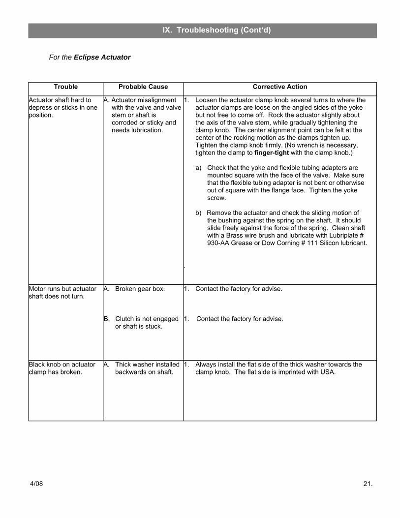
Trouble Probable Cause Corrective Action
Actuator shaft hard to depress or sticks in one position.
A. Actuator misalignment with the valve and valve stem or shaft is corroded or sticky and needs lubrication.
1. Loosen the actuator clamp knob several turns to where the actuator clamps are loose on the angled sides of the yoke but not free to come off. Rock the actuator slightly about the axis of the valve stem, while gradually tightening the clamp knob. The center alignment point can be felt at the center of the rocking motion as the clamps tighten up. Tighten the clamp knob firmly. (No wrench is necessary, tighten the clamp to finger-tight with the clamp knob.)
a) Check that the yoke and flexible tubing adapters are
mounted square with the face of the valve. Make sure that the flexible tubing adapter is not bent or otherwise out of square with the flange face. Tighten the yoke screw.
b) Remove the actuator and check the sliding motion of
the bushing against the spring on the shaft. It should slide freely against the force of the spring. Clean shaft with a Brass wire brush and lubricate with Lubriplate # 930-AA Grease or Dow Corning # 111 Silicon lubricant.
.
Motor runs but actuator shaft does not turn.
A. Broken gear box. B. Clutch is not engaged
or shaft is stuck.
1. Contact the factory for advise. 1. Contact the factory for advise.
Black knob on actuator clamp has broken.
A. Thick washer installed backwards on shaft.
1. Always install the flat side of the thick washer towards the clamp knob. The flat side is imprinted with USA.
For the Eclipse Actuator
lX. Troubleshooting (Cont‘d)
4/08 22.
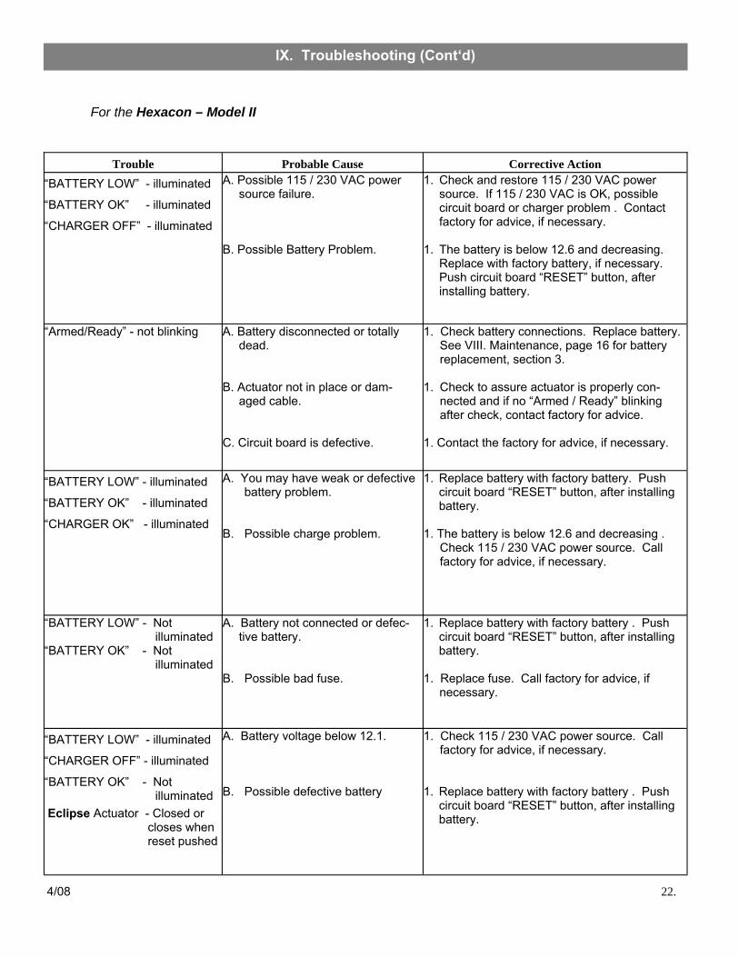
For the Hexacon – Model II
Trouble Probable Cause Corrective Action “BATTERY LOW” - illuminated
“BATTERY OK” - illuminated
“CHARGER OFF” - illuminated
A. Possible 115 / 230 VAC power source failure.
B. Possible Battery Problem.
1. Check and restore 115 / 230 VAC power source. If 115 / 230 VAC is OK, possible circuit board or charger problem . Contact factory for advice, if necessary.
1. The battery is below 12.6 and decreasing.
Replace with factory battery, if necessary. Push circuit board “RESET” button, after installing battery.
“BATTERY LOW” - illuminated
“BATTERY OK” - illuminated
“CHARGER OK” - illuminated
A. You may have weak or defective battery problem.
B. Possible charge problem.
1. Replace battery with factory battery. Push circuit board “RESET” button, after installing battery.
1. The battery is below 12.6 and decreasing .
Check 115 / 230 VAC power source. Call factory for advice, if necessary.
“BATTERY LOW” - illuminated
“CHARGER OFF” - illuminated
“BATTERY OK” - Not illuminated Eclipse Actuator - Closed or
closes when reset pushed
A. Battery voltage below 12.1. B. Possible defective battery
1. Check 115 / 230 VAC power source. Call factory for advice, if necessary.
1. Replace battery with factory battery . Push
circuit board “RESET” button, after installing battery.
“Armed/Ready” - not blinking A. Battery disconnected or totally dead.
B. Actuator not in place or dam-
aged cable. C. Circuit board is defective.
1. Check battery connections. Replace battery. See VIII. Maintenance, page 16 for battery replacement, section 3.
1. Check to assure actuator is properly con-
nected and if no “Armed / Ready” blinking after check, contact factory for advice.
1. Contact the factory for advice, if necessary.
“BATTERY LOW” - Not illuminated “BATTERY OK” - Not illuminated
A. Battery not connected or defec-tive battery.
B. Possible bad fuse.
1. Replace battery with factory battery . Push circuit board “RESET” button, after installing battery.