1 ECM PROCESS CHARACTERISTICS A PROJECT SUBMITTED IN PARTIAL FULFILLMENT OF THE REQUIREMENT FOR THE DEGREE OF Bachelor of Technology In Mechanical Engineering Submitted by: ANIL KUMAR MEHER ROLL NO. : 10503046 Department of Mechanical Engineering National Institute of Technology Rourkela 2009
Transcript
1
ECM PROCESS CHARACTERISTICS
A PROJECT SUBMITTED IN PARTIAL FULFILLMENT
OF THE REQUIREMENT FOR THE DEGREE OF
Bachelor of Technology
In
Mechanical Engineering
Submitted by:
ANIL KUMAR MEHER
ROLL NO. : 10503046
Department of Mechanical Engineering
National Institute of Technology
Rourkela
2009
2
ECM PROCESS CHARACTERISTICS
A PROJECT SUBMITTED IN PARTIAL FULFILLMENT
OF THE REQUIREMENT FOR THE DEGREE OF
Bachelor of Technology
In
Mechanical Engineering
Submitted by:
ANIL KUMAR MEHER
ROLL NO. : 10503046
Under the guidance of:
Prof. B. K. NANDA
Department of Mechanical Engineering
National Institute of Technology
Rourkela
2009
3
National Institute of Technology
Rourkela 2009
CERTIFICATE
This is to certify that the thesis entitled, “Electrochemical Machining (ECM) Process
Characteristics” submitted by Mr. Anil Kumar Meher, Roll No: 10503046, in partial fulfillment
of the requirements for the award of Bachelor of Technology Degree in Mechanical Engineering
at the National Institute of Technology, Rourkela (Deemed University) is an authentic work
carried out by him under my supervision and guidance .
To the best of my knowledge, the matter embodied in the thesis has not been submitted to
any other University / Institute for the award of any Degree or Diploma.
Date: 12.5.2009 Professor B. K. Nanda
Department of Mechanical Engineering
National Institute of Technology
Rourkela
2009
4
ACKNOWLEDGEMENT
I am thankful to Prof. B. K. Nanda, Professor in the department of Mechanical Engineering,
NIT Rourkela for giving me the opportunity to work under him and lending every support at
every stage of this project work. I would also like to convey my sincerest gratitude to all other
faculty members and staff of Department of Mechanical Engineering, NIT Rourkela, who
bestowed their great effort and guidance at appropriate times without which it would have been
very difficult on my part to finish the project work.
Date: May 12, 2009 Anil Kumar Meher
Roll No: 10503046
Mechanical Engineering,
National Institute of technology,
Rourkela
5
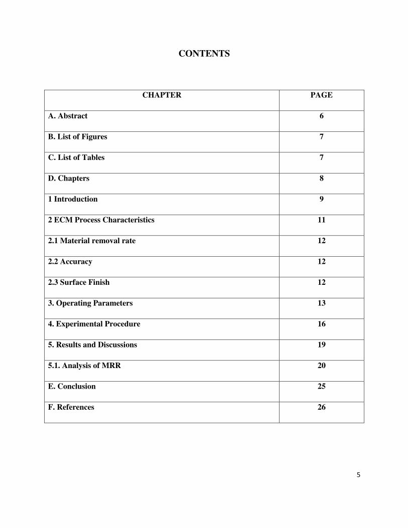
CONTENTS
CHAPTER PAGE
A. Abstract 6
B. List of Figures 7
C. List of Tables 7
D. Chapters 8
1 Introduction 9
2 ECM Process Characteristics 11
2.1 Material removal rate 12
2.2 Accuracy 12
2.3 Surface Finish 12
3. Operating Parameters 13
4. Experimental Procedure 16
5. Results and Discussions 19
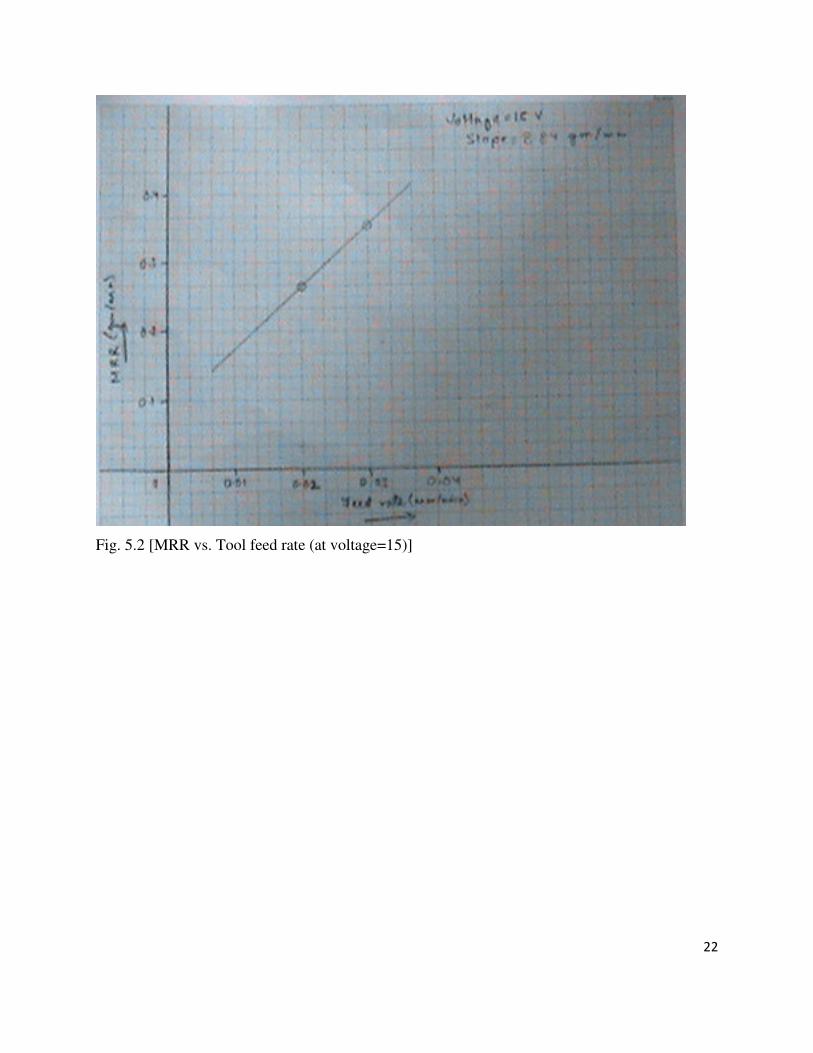
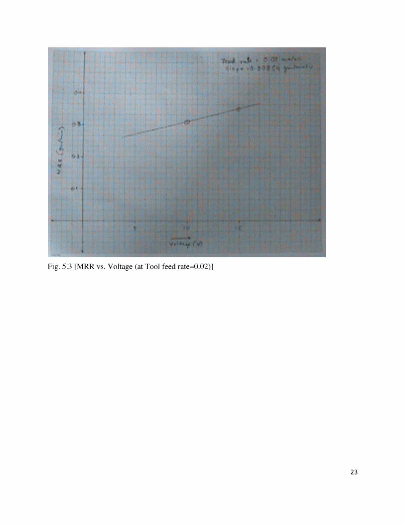
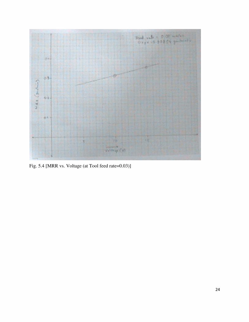
5.1. Analysis of MRR 20
E. Conclusion 25
F. References 26
6
Abstract:
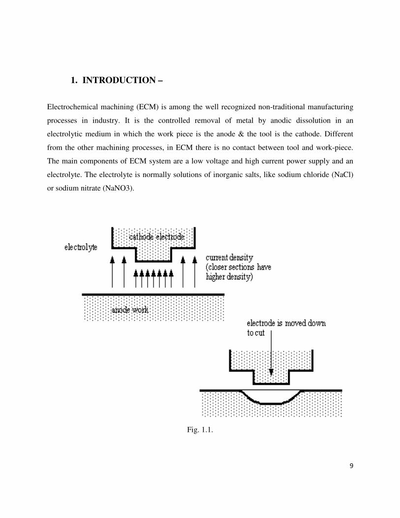
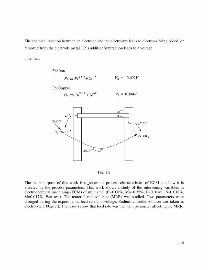
This paper intends to deal with the process characteristics of ECM and how it is affected by the
process parameters. This work shows a study of the intervening variables in electrochemical