Page 1
1
Eco-friendly Cooling System Design for a Hostel Building
Nikhil Malviya*, Prashant Akhilesh Tiwari*, Dilawar Husain*, Ravi Prakash*1
Affiliation: *Motilal Nehru National Institute of Technology, Allahabad, Prayagraj,(UP) India
1Email: [email protected]
Mobile: +91-9336668662
Abstract
In order to provide thermal comfort in a tropical country like India, the use of conventional
window air-conditioners is very much electricity intensive, which may lead to a further
increase in the greenhouse gas (GHG) emissions. A significant economic and environmental
advantage can be achieved by adopting modified air cooling systems. This paper presents a
case study for proposing a design of an energy-efficient and affordable cooling system for a
hostel building located at the Motilal Nehru National Institute of Technology, Allahabad
located at Prayagraj (UP), India. The design consists of a solar electricity-based centralized
chilled water air conditioning system and an earth air heat exchanger (EAHE) as a passive
cooling solution. The EAHE takes advantage of the fact that at a depth of 4 meters, the
earth’s temperature remains constant throughout the year. An earth air tunnel can provide
year round thermal comfort i.e. both heating and cooling depending on inlet air temperature.
Simulation showed that, when air is blown at 6.2 m/s velocity through a 70 meter long EAHE
with 0.5 meter diameter, the temperature changes from 45°C to 26°C in summers and from
4°C to 16°C in winters. The chilled water AC system is designed for operation with a smart
solar grid electricity connection. Results obtained for the solar driven AC system showed
that, for a building with 328 TR cooling load, only 65 tCO2 emission are produced annually,
which would have been 928 tCO2 if connected through grid electricity. This reflects 93%
potential reduction in GHG emissions.
Keywords: Sustainable Systems, Energy Efficient Design, Earth Air Heat Exchanger,
Thermal Comfort, Renewable System.
1. Introduction
Global warming and urban heat island increase the demand of thermal comfort inside the
built envelope. The most common solution is to use mechanical air-conditioning (AC)
systems. But for the large cooling requirement (such as in hostels, hospitals, theatres etc.),
this solution proves to be very energy intensive.
Page 2
2
For large buildings or campuses with multiple building use, water chiller plants for air
conditioning are preferred, as compared to window air-conditioners. It normally consists of
chillers, cooling towers, pumps and chilled water storage tanks. More than 40% electricity in
building is consumed to maintain thermal comfort (Perez-Lombard et al. 2008). Several
studies have been reported in the literature for effective management of chiller plants
required to save energy and reduce its environment impact. Xiupeng et al. (2014) provided
data-driven approach, which was employed to optimize the operation of a chiller plant having
multiple chillers. The optimal sequencing of these chillers can improve the plant
performance. Chang et al. (2005) proposed branch and bound (B&B) method to solve the
optimal chiller sequencing (OCS) problem and to eliminate the deficiencies of conventional
methods. They used Lagrangian method that determines the optimal chiller loading (OCL) in
each feasible state. Since air conditioning systems consume large amount of electricity in
residential, commercial and industrial buildings, hence the search for energy-optimized
systems is an urgent need worldwide. This can be done either by producing systems that
consume less energy or to use energy from renewable sources. Husnain and Alabbadi,
(2000) reported that that the thermal energy storage will reduce the peak cooling-
load demand by approximately 30-40% and the peak electrical demand by
approximately 10-20%.Leite et al. (2019) presented a technical and economic analysis of
air conditioning systems connected to the grid electricity integrated with solar photovoltaic,
as a complementary energy source. They analysed two different systems (variable
refrigerant flow and water chillers) for two cities in Brazil i.e. Recife and São Paulo, with
varying levels of solar radiation and temperature. The authors also applied a mathematical
model to evaluate the economic benefits of the integrated use of these systems. They
showed that this implementation of air conditioning systems with solar photovoltaic energy
could assure high internal rate of return for both cities, with average values around 28% for
Recife and 22% for São Paulo,.
Several researchers have studied the use of ground as heat source and sink. Bisoniya et al.
(2015) carried out a study to evaluate annual thermal performance of earth air heat
exchanger (EAHE) system for hot and dry climatic conditions of Bhopal (Central India). The
maximum heating potential and cooling potential of EAHE obtained in the months of January
and May, respectively, were calculated as 191.06 kWh and 247.25 kWh. The CO2 emission
mitigation potential was calculated as 101.30 tonnes considering its life span as 50 years.
Bansal et al. (2013) studied the underground temperature characteristics of the soil
surrounding the EAHE pipe and the effect of duration of operation of EAHE on its thermal
performance. Maximum air temperature drop of 15.6, 17.0 and 17.3 K were observed for soil
thermal conductivities of 0.52, 2 and 4 W/m.K, respectively. Mahmoud & Nabil (2019)
Page 3
3
proposed air pre-cooling by inducing ambient air to earth air heat exchanger instead of
directly supplying it to thermal systems. Results of the study show that on an average daily
basis, a significant induced air temperature drop of 23.5 °C was achieved at the soil
moisture content of 30%. Al-Ajmi et al. (2006) developed a theoretical model of an earth air
heat exchanger (EAHE) for predicting the outlet air temperature and cooling potential of
these devices in a hot, arid climate. Simulation results showed that the EAHE could provide
a reduction of 1700W in the peak cooling load, with an indoor temperature reduction of 2.8
°C during summer peak hours (middle of July). The EAHE was shown to have the potential
for reducing cooling energy demand in a typical house by 30% over the peak summer
season. Jakhar et al. (2015) found that the heating capacity of EAHE system increased by
1217–1280 kWh when it was coupled with solar air heating duct with a substantial increase
in room temperature by 1.1 - 3.5 °C.
The objective of the study presented in this paper is to examine sustainable cooling options
for a student hostel building on the campus of an engineering institute located in the tropical
city of Prayagraj, UP, India. The sustainable options considered are centralized chilled water
solar driven AC system and an EAHE system for providing year round thermal comfort.
2. Methodology
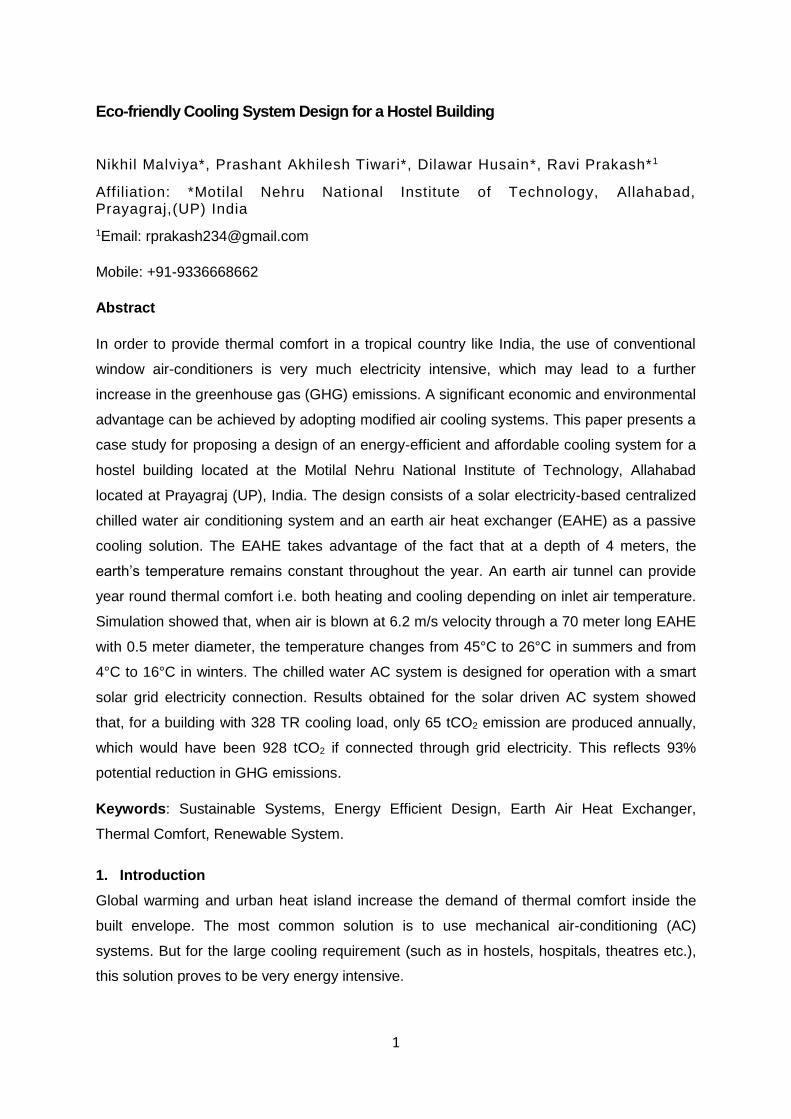
This case study was carried out for the SV Patel Hostel, located at MNNIT Allahabad
campus in Teliarganj, Prayagraj (25.49° N, 81.86° E), India. It is a two floor building with total
333 rooms and covers 31857 square ft area (287 x 111 sq. ft). It is has eight wings and each
wing consists of 15 rooms. Each room area is 82 sq. ft (8.2x10 sq. ft) and has a window
opening (3x5 sq. ft), and a door (3x6.7 sq. ft). The CAD model of the building under
consideration is shown in Figure 1.
Figure 1 Google satellite image of study site and is top view drawn in AUTOCAD 2018
2.1 Cooling Load Calculation
For cooling load calculation, Quick Energy Simulation Tool (eQUEST) software was used. It
allows users with limited simulation experience to develop 3-dimensional simulation models
Page 4
4
of a particular building design. These simulations incorporate building location, orientation,
wall/roof construction, window properties, as well as HVAC systems, day-lighting and
various control strategies, along with the ability to evaluate design options for any single or
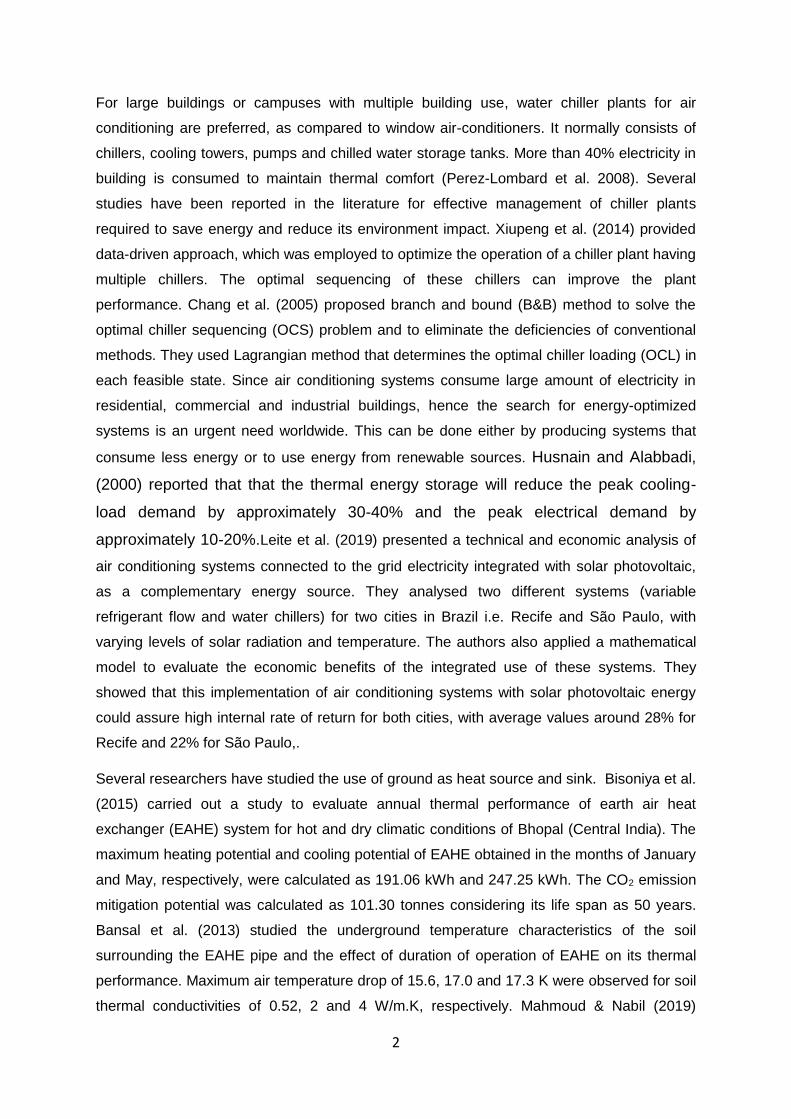
combination of energy conservation measure(s). Such a model for building under
consideration is shown in Figure 2.
Figure 2 3-D model of building under consideration developed on eQUEST
The software parameter settings also incorporate building envelope model, common brick
walls used for building wall construction, concrete roof construction, with glass window and
wooden door. Other than these, it also considers daily occupancy for load calculation.
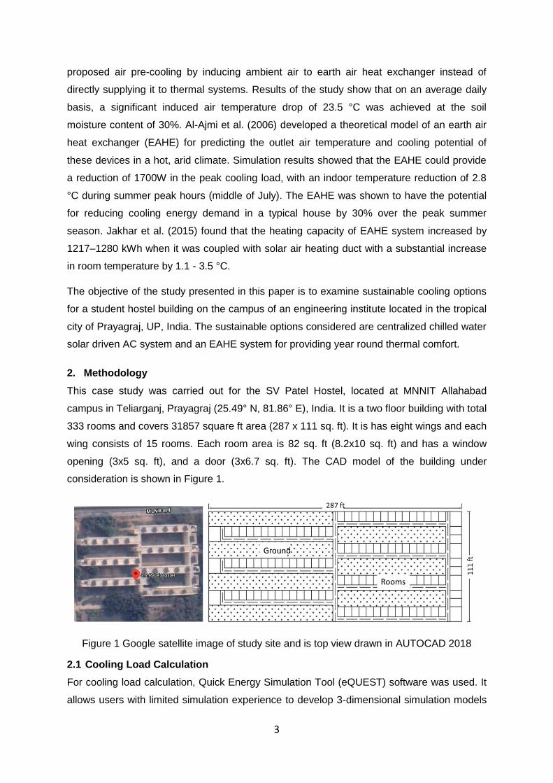
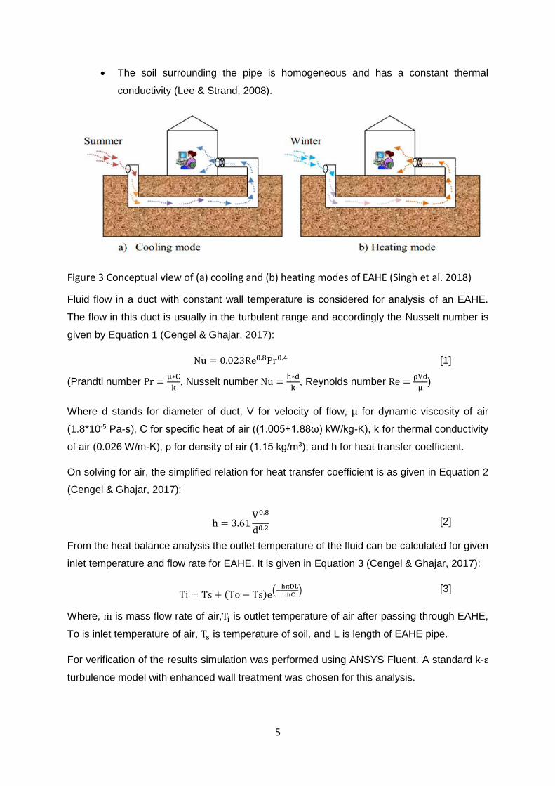
2.2 Earth air heat exchanger
The simplest EAHE can be a pipe of an appropriate dimension buried at a certain depth
(generally 4 m) through which air flows (Singh et al. 2018). For winter and summer season,
schematic diagram of EAHEs is shown in Figures 3 (a, b). During the summer season, the
hot ambient air transfers its heat to the buried pipe and gets cooled (Figure 3a), while in the
winter season, the cold ambient air gets heated in the buried pipe (Figure 3b). Due to the
complex mechanisms occurring around the earth tube, several simplifying assumptions were
made:
The soil surrounding the pipe is isotropic, with homogenous thermal conductivity
in all ground strata (Barakat et al. 2016).
The thermal resistance of the pipe material is negligible (thickness of the pipe is
very small) (Al-Ajmi et al. 2006).
The pipe is of uniform circular cross-section.
The temperature profile in the pipe vicinity is not affected by the presence of the
pipe. As a result, the pipe surface temperature is uniform in the axial direction
(Lee & Strand, 2008).
Page 5
5
The soil surrounding the pipe is homogeneous and has a constant thermal
conductivity (Lee & Strand, 2008).
Figure 3 Conceptual view of (a) cooling and (b) heating modes of EAHE (Singh et al. 2018)
Fluid flow in a duct with constant wall temperature is considered for analysis of an EAHE.
The flow in this duct is usually in the turbulent range and accordingly the Nusselt number is
given by Equation 1 (Cengel & Ghajar, 2017):
Nu = 0.023Re0.8Pr0.4 [1]
(Prandtl number Pr =µ∗C
k, Nusselt number Nu =
h∗d
k, Reynolds number Re =
ρVd
µ)
Where d stands for diameter of duct, V for velocity of flow, µ for dynamic viscosity of air
(1.8*10-5 Pa-s), C for specific heat of air ((1.005+1.88ω) kW/kg-K), k for thermal conductivity
of air (0.026 W/m-K), ρ for density of air (1.15 kg/m3), and h for heat transfer coefficient.
On solving for air, the simplified relation for heat transfer coefficient is as given in Equation 2
(Cengel & Ghajar, 2017):
h = 3.61V0.8
d0.2 [2]
From the heat balance analysis the outlet temperature of the fluid can be calculated for given
inlet temperature and flow rate for EAHE. It is given in Equation 3 (Cengel & Ghajar, 2017):
Ti = Ts + (To − Ts)e(−
hπDL
mC)
[3]
Where, m is mass flow rate of air,Ti is outlet temperature of air after passing through EAHE,
To is inlet temperature of air, Ts is temperature of soil, and L is length of EAHE pipe.
For verification of the results simulation was performed using ANSYS Fluent. A standard k-ε
turbulence model with enhanced wall treatment was chosen for this analysis.
Page 6
6
2.3 Chilled water AC system
The chilled water distribution system consists of chillers, pumps, piping, cooling coils,
controls and other components on the evaporator side of the chillers. The chiller unit works
on vapour compression cycle. This case study demonstrates chilled water plant designed to
circulate constant volume of chilled water through the chiller(s) to the building. Such systems
are called constant flow chilled water system. The constant-flow systems can be used in the
following configurations:
Single chiller serving a single cooling load
Single chiller with multiple cooling loads
Multiple parallel chillers with multiple cooling loads
Multiple series chillers with multiple loads
This case study demonstrated the multiple parallel chillers with multiple cooling loads
configuration. This is due to safety and better maintenance, which can be achieved in this
configuration. Also due to parallel chiller configuration, this system may further be extended
to more cooling capacity by just adding chillers to the main header.
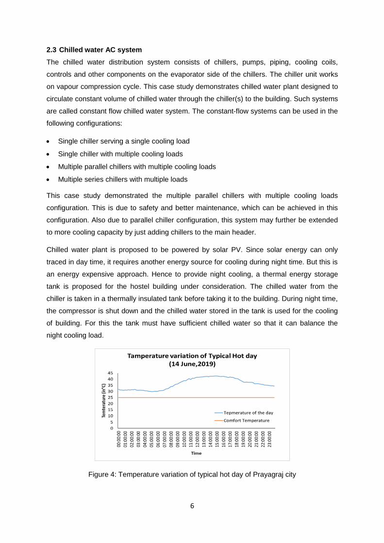
Chilled water plant is proposed to be powered by solar PV. Since solar energy can only
traced in day time, it requires another energy source for cooling during night time. But this is
an energy expensive approach. Hence to provide night cooling, a thermal energy storage
tank is proposed for the hostel building under consideration. The chilled water from the
chiller is taken in a thermally insulated tank before taking it to the building. During night time,
the compressor is shut down and the chilled water stored in the tank is used for the cooling
of building. For this the tank must have sufficient chilled water so that it can balance the
night cooling load.
Figure 4: Temperature variation of typical hot day of Prayagraj city
Page 7
7
Following consideration are taken for designing of chilled water storage tank, taking in view
of the temperature profile shown in Figure 4.
It is assumed that solar energy is sufficiently available from 8:00 am to 6:00 pm
and hence can be used for chilled water production.
Chilled water is needed to be stored for providing cooling in night time when
compressor is in off mode. This period is considered to be of 14 hr (from 6:00 pm
to 8:00 am).
During day hours the ambient temperature is about 16°C -20°C more than the
comfort temperature i.e. 25 °C (as shown in the Figure 4).
While in night time ambient temperature is about 8°C -10°C more than the
comfort temperature reduction. Hence cooling load during night can be taken
about half of the cooling load in day time.
Chilled water produced at 6°C will provide effective cooling till it reaches up to
16°C.
So, considering all above mentioned points, the chilled water storage tank is designed for
half of maximum cooling load and 14 hours of daily operation.
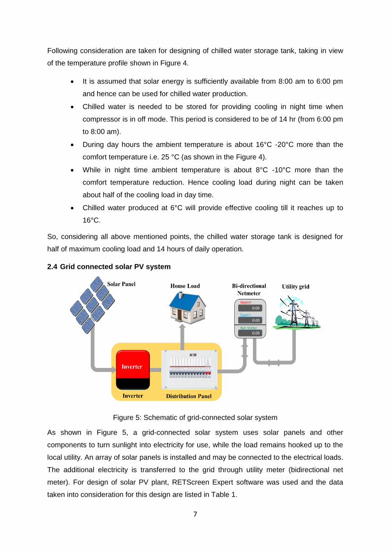
2.4 Grid connected solar PV system
Figure 5: Schematic of grid-connected solar system
As shown in Figure 5, a grid-connected solar system uses solar panels and other
components to turn sunlight into electricity for use, while the load remains hooked up to the
local utility. An array of solar panels is installed and may be connected to the electrical loads.
The additional electricity is transferred to the grid through utility meter (bidirectional net
meter). For design of solar PV plant, RETScreen Expert software was used and the data
taken into consideration for this design are listed in Table 1.
Page 8
8
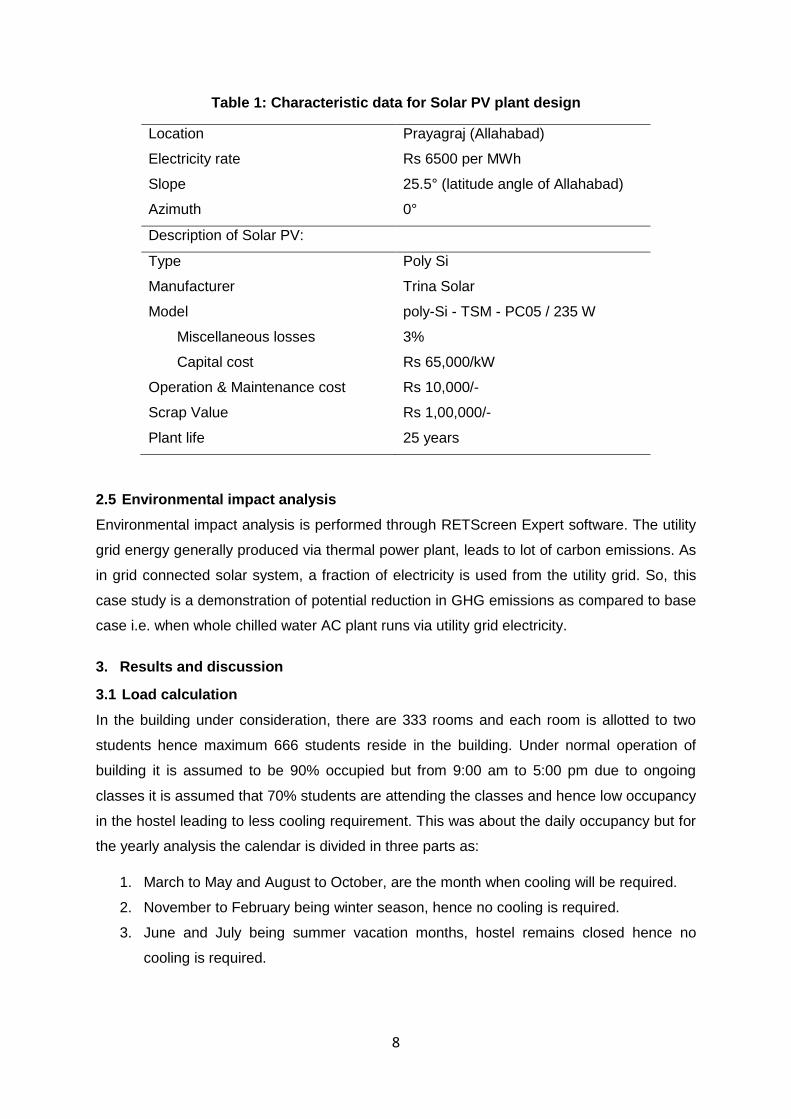
Table 1: Characteristic data for Solar PV plant design
Location Prayagraj (Allahabad)
Electricity rate Rs 6500 per MWh
Slope 25.5° (latitude angle of Allahabad)
Azimuth 0°
Description of Solar PV:
Type Poly Si
Manufacturer Trina Solar
Model poly-Si - TSM - PC05 / 235 W
Miscellaneous losses 3%
Capital cost Rs 65,000/kW
Operation & Maintenance cost Rs 10,000/-
Scrap Value Rs 1,00,000/-
Plant life 25 years
2.5 Environmental impact analysis
Environmental impact analysis is performed through RETScreen Expert software. The utility
grid energy generally produced via thermal power plant, leads to lot of carbon emissions. As
in grid connected solar system, a fraction of electricity is used from the utility grid. So, this
case study is a demonstration of potential reduction in GHG emissions as compared to base
case i.e. when whole chilled water AC plant runs via utility grid electricity.
3. Results and discussion
3.1 Load calculation
In the building under consideration, there are 333 rooms and each room is allotted to two
students hence maximum 666 students reside in the building. Under normal operation of
building it is assumed to be 90% occupied but from 9:00 am to 5:00 pm due to ongoing
classes it is assumed that 70% students are attending the classes and hence low occupancy
in the hostel leading to less cooling requirement. This was about the daily occupancy but for
the yearly analysis the calendar is divided in three parts as:
1. March to May and August to October, are the month when cooling will be required.
2. November to February being winter season, hence no cooling is required.
3. June and July being summer vacation months, hostel remains closed hence no
cooling is required.
Page 9
9
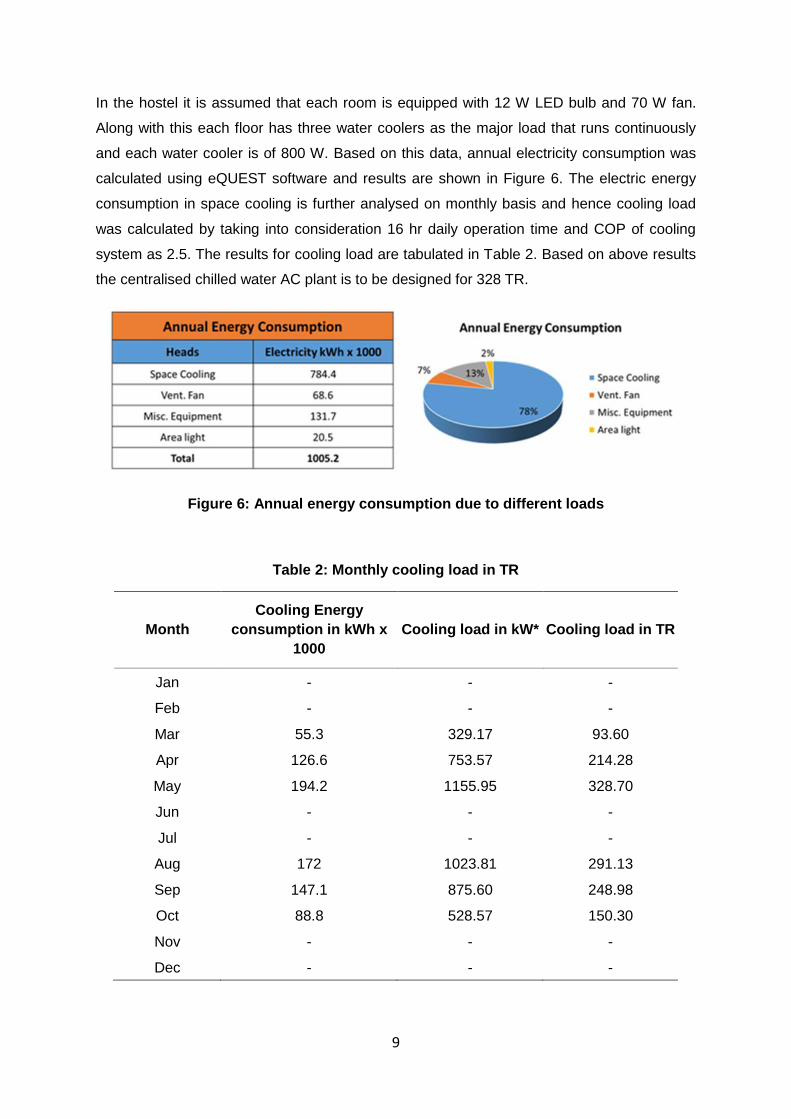
In the hostel it is assumed that each room is equipped with 12 W LED bulb and 70 W fan.
Along with this each floor has three water coolers as the major load that runs continuously
and each water cooler is of 800 W. Based on this data, annual electricity consumption was
calculated using eQUEST software and results are shown in Figure 6. The electric energy
consumption in space cooling is further analysed on monthly basis and hence cooling load
was calculated by taking into consideration 16 hr daily operation time and COP of cooling
system as 2.5. The results for cooling load are tabulated in Table 2. Based on above results
the centralised chilled water AC plant is to be designed for 328 TR.
Figure 6: Annual energy consumption due to different loads
Table 2: Monthly cooling load in TR
Month
Cooling Energy
consumption in kWh x
1000
Cooling load in kW* Cooling load in TR
Jan - - -
Feb - - -
Mar 55.3 329.17 93.60
Apr 126.6 753.57 214.28
May 194.2 1155.95 328.70
Jun - - -
Jul - - -
Aug 172 1023.81 291.13
Sep 147.1 875.60 248.98
Oct 88.8 528.57 150.30
Nov - - -
Dec - - -
Page 10
10
3.2 Earth air heat exchanger
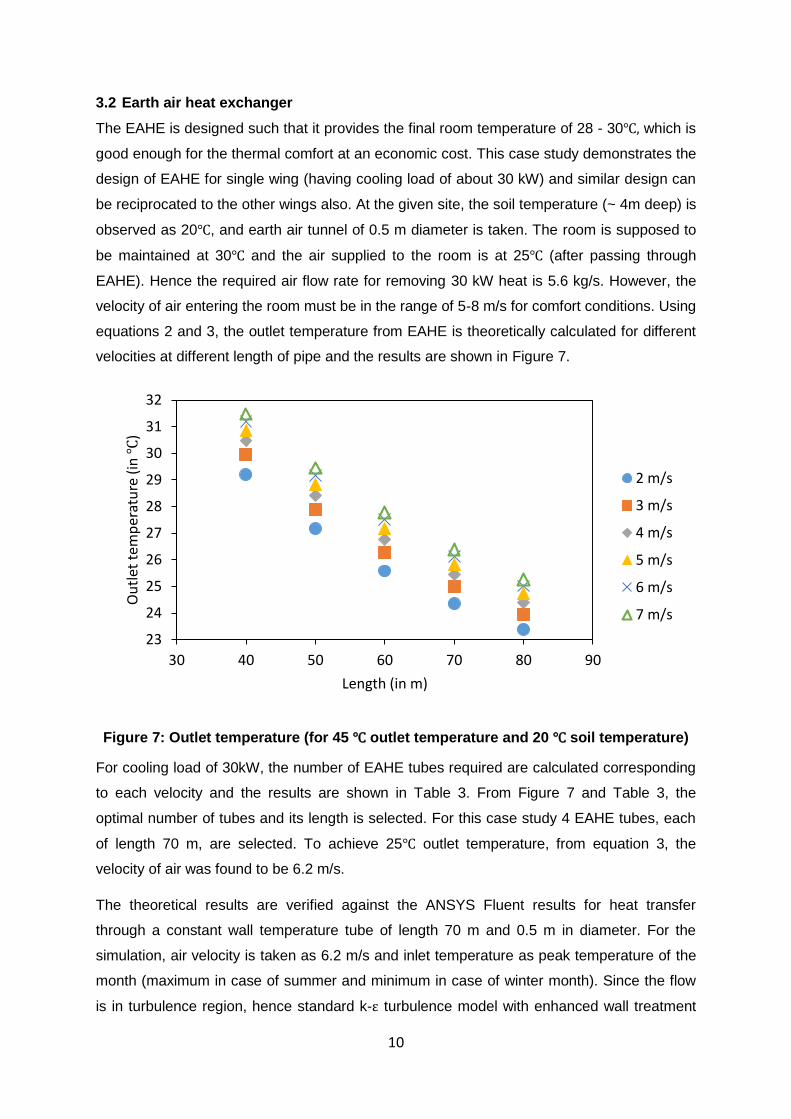
The EAHE is designed such that it provides the final room temperature of 28 - 30℃, which is
good enough for the thermal comfort at an economic cost. This case study demonstrates the
design of EAHE for single wing (having cooling load of about 30 kW) and similar design can
be reciprocated to the other wings also. At the given site, the soil temperature (~ 4m deep) is
observed as 20℃, and earth air tunnel of 0.5 m diameter is taken. The room is supposed to
be maintained at 30℃ and the air supplied to the room is at 25℃ (after passing through
EAHE). Hence the required air flow rate for removing 30 kW heat is 5.6 kg/s. However, the
velocity of air entering the room must be in the range of 5-8 m/s for comfort conditions. Using
equations 2 and 3, the outlet temperature from EAHE is theoretically calculated for different
velocities at different length of pipe and the results are shown in Figure 7.
Figure 7: Outlet temperature (for 45 ℃ outlet temperature and 20 ℃ soil temperature)
For cooling load of 30kW, the number of EAHE tubes required are calculated corresponding
to each velocity and the results are shown in Table 3. From Figure 7 and Table 3, the
optimal number of tubes and its length is selected. For this case study 4 EAHE tubes, each
of length 70 m, are selected. To achieve 25℃ outlet temperature, from equation 3, the
velocity of air was found to be 6.2 m/s.
The theoretical results are verified against the ANSYS Fluent results for heat transfer
through a constant wall temperature tube of length 70 m and 0.5 m in diameter. For the
simulation, air velocity is taken as 6.2 m/s and inlet temperature as peak temperature of the
month (maximum in case of summer and minimum in case of winter month). Since the flow
is in turbulence region, hence standard k-ε turbulence model with enhanced wall treatment
23
24
25
26
27
28
29
30
31
32
30 40 50 60 70 80 90
Ou
tlet
tem
per
atu
re (
in ℃
)
Length (in m)
2 m/s
3 m/s
4 m/s
5 m/s
6 m/s
7 m/s
Page 11
11
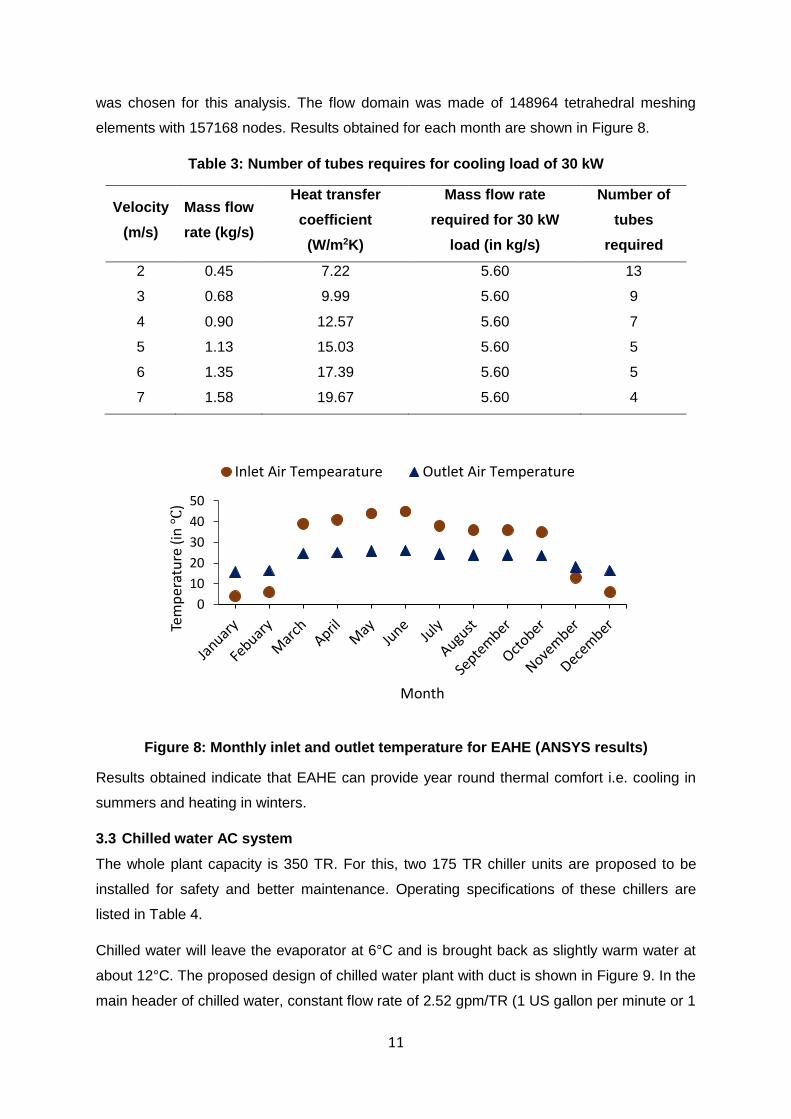
was chosen for this analysis. The flow domain was made of 148964 tetrahedral meshing
elements with 157168 nodes. Results obtained for each month are shown in Figure 8.
Table 3: Number of tubes requires for cooling load of 30 kW
Velocity
(m/s)
Mass flow
rate (kg/s)
Heat transfer
coefficient
(W/m2K)
Mass flow rate
required for 30 kW
load (in kg/s)
Number of
tubes
required
2 0.45 7.22 5.60 13
3 0.68 9.99 5.60 9
4 0.90 12.57 5.60 7
5 1.13 15.03 5.60 5
6 1.35 17.39 5.60 5
7 1.58 19.67 5.60 4
Figure 8: Monthly inlet and outlet temperature for EAHE (ANSYS results)
Results obtained indicate that EAHE can provide year round thermal comfort i.e. cooling in
summers and heating in winters.
3.3 Chilled water AC system
The whole plant capacity is 350 TR. For this, two 175 TR chiller units are proposed to be
installed for safety and better maintenance. Operating specifications of these chillers are
listed in Table 4.
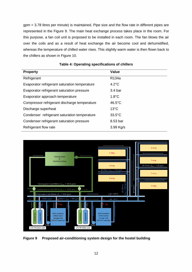
Chilled water will leave the evaporator at 6°C and is brought back as slightly warm water at
about 12°C. The proposed design of chilled water plant with duct is shown in Figure 9. In the
main header of chilled water, constant flow rate of 2.52 gpm/TR (1 US gallon per minute or 1
0
10
20
30
40
50
Tem
per
atu
re (
in ℃
)
Month
Inlet Air Tempearature Outlet Air Temperature
Page 12
12
gpm = 3.78 litres per minute) is maintained. Pipe size and the flow rate in different pipes are
represented in the Figure 9. The main heat exchange process takes place in the room. For
this purpose, a fan coil unit is proposed to be installed in each room. The fan blows the air
over the coils and as a result of heat exchange the air become cool and dehumidified,
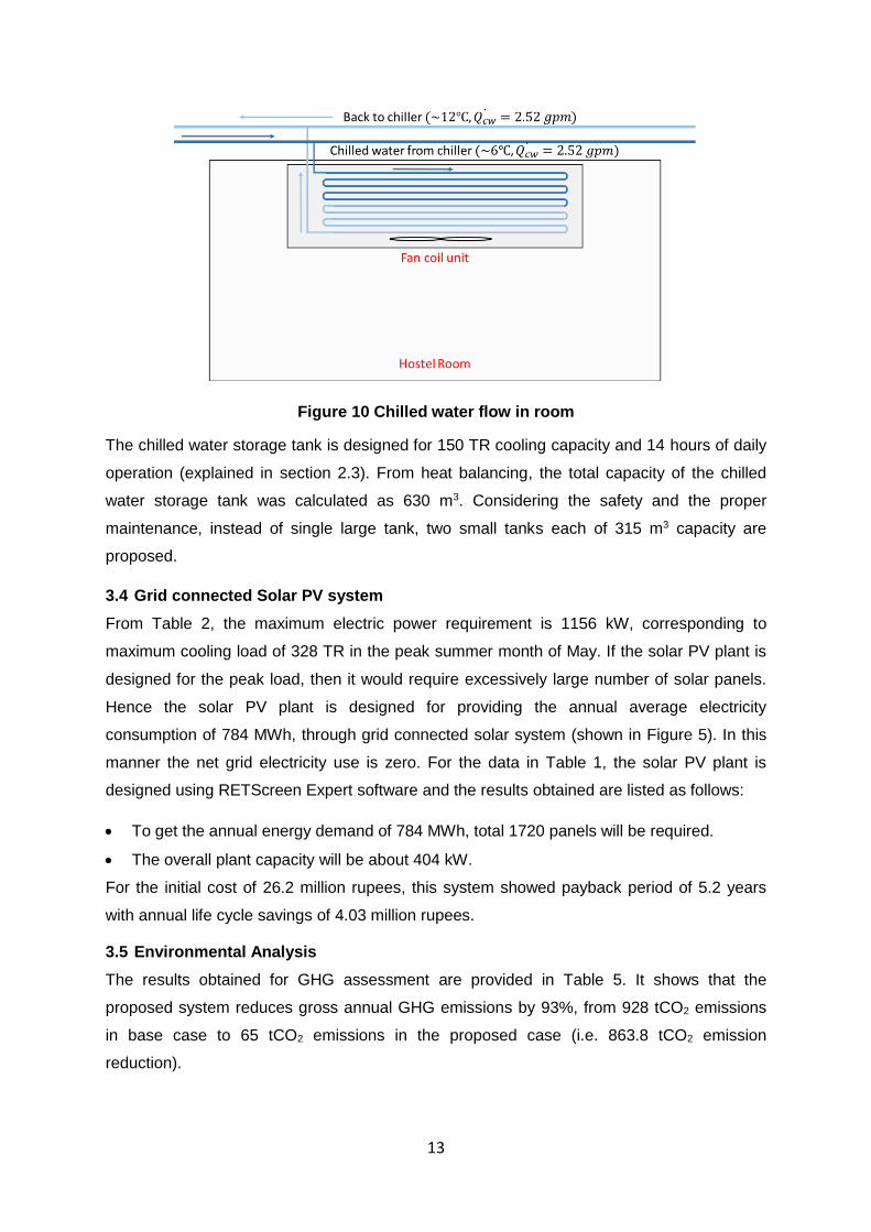
whereas the temperature of chilled water rises. This slightly warm water is then flown back to
the chillers as shown in Figure 10.
Table 4: Operating specifications of chillers
Property Value
Refrigerant R134a
Evaporator refrigerant saturation temperature 4.2°C
Evaporator refrigerant saturation pressure 3.4 bar
Evaporator approach temperature 1.8°C
Compressor refrigerant discharge temperature 46.5°C
Discharge superheat 13°C
Condenser refrigerant saturation temperature 33.5°C
Condenser refrigerant saturation pressure 8.53 bar
Refrigerant flow rate 3.99 Kg/s
Figure 9 Proposed air-conditioning system design for the hostel building
Page 13
13
Figure 10 Chilled water flow in room
The chilled water storage tank is designed for 150 TR cooling capacity and 14 hours of daily
operation (explained in section 2.3). From heat balancing, the total capacity of the chilled
water storage tank was calculated as 630 m3. Considering the safety and the proper
maintenance, instead of single large tank, two small tanks each of 315 m3 capacity are
proposed.
3.4 Grid connected Solar PV system
From Table 2, the maximum electric power requirement is 1156 kW, corresponding to
maximum cooling load of 328 TR in the peak summer month of May. If the solar PV plant is
designed for the peak load, then it would require excessively large number of solar panels.
Hence the solar PV plant is designed for providing the annual average electricity
consumption of 784 MWh, through grid connected solar system (shown in Figure 5). In this
manner the net grid electricity use is zero. For the data in Table 1, the solar PV plant is
designed using RETScreen Expert software and the results obtained are listed as follows:
To get the annual energy demand of 784 MWh, total 1720 panels will be required.
The overall plant capacity will be about 404 kW.
For the initial cost of 26.2 million rupees, this system showed payback period of 5.2 years
with annual life cycle savings of 4.03 million rupees.
3.5 Environmental Analysis
The results obtained for GHG assessment are provided in Table 5. It shows that the
proposed system reduces gross annual GHG emissions by 93%, from 928 tCO2 emissions
in base case to 65 tCO2 emissions in the proposed case (i.e. 863.8 tCO2 emission
reduction).
Page 14
14
Table 5: GHG emissions in base case and proposed case
Annual GHG emissions (tCO2e)
Base case (utility grid electricity)
928.8 Proposed case
65.0
Gross annual GHG emission reduction
863.8
4. Conclusions
Greater use of air conditioning will demand more electricity leading to increased GHG
emissions. This case study demonstrated energy efficient and environment friendly
technologies for providing thermal comfort for a hostel building. The EAHE would be used for
heating in winters and cooling in summers at approximately equal effectiveness at very low
cost unlike AC system which costs much more. Central chilled water AC plant is much more
effective as compared to individual window ACs, particularly when deigned to run on solar
energy. As shown in this study grid connected solar system for the central chilled water AC
plant reduced the GHG emission levels by 93%. The detailed economic comparison of the
two options presented in this case study needs to be carried out. However, the EAHE option
will definitely be much more economical with additional advantage of providing heating in
winters.
References
1) Al-Ajmi F, Loveday D.L., Hanby V.I. (2006), The cooling potential of earth–air heat
exchangers for domestic buildings in a desert climate, Building and Environment 41,
235–244.
2) Bansal V., Misra R., Agarwal G. D. (2013), Jyotirmay Mathur, Transient effect of soil
thermal conductivity and duration of operation on performance of Earth Air Tunnel Heat
Exchanger, Applied Energy 103, 1–11.
3) Barakat S., Ramzy A, Hamed A. M., El Emam S H (2016), Enhancement of gas turbine
power output using earth to air heat exchanger (EAHE) cooling system, Energy
Conversion and Management 111, 137–146.
4) Bisoniya T. S., Kumar A, Baredar P. (2015), Energy metrics of earth–air heat exchanger
system for hot and dry climatic conditions of India, Energy and Buildings 86, 214–221
5) Cengel, Y.A., Ghajar, A..J., 2017 “Heat and Mass Transfer: Fundamentals and
Applications”, Edition 5, McGraw Hill, ISBN-10: 9789339223199
6) Chang YC, Lin FA, Lin CH. (2005), Optimal chiller sequencing by branch and bound
method for saving energy. Energy Conversion and Management, 46, 2158-2172.
Page 15
15
7) Hasnain S. M., Alabbadi N. M. (2000), Need for thermal-storage air-conditioning in Saudi
Arabia, Applied Energy 65, 153-164.
8) Jakhar S., Misra R, Bansal V., Soni M.S. (2015), Thermal performance investigation of
earth air tunnel heat exchanger coupled with a solar air heating duct for north-western
India, Energy and Buildings 87, 360–369.
9) Lee K.H., Strand R. K. (2008), The cooling and heating potential of an earth tube system
in buildings, Energy and buildings 40, 486-494.
10) Leite GDNP, Weschenfelder F, Araújo A.M, Villa Ochoa A. A., Prestrelo Neto N A, Kraj
A. (2019), An economic analysis of the integration between air-conditioning and solar
photovoltaic systems, Energy Conversion and Management, 185, 836–849.
11) Mahmoud B., Nabil A.S. (2019), Enhancing the Performance of Dry Air-Cooled Systems
with Wet Geothermal Cooling in Saudi Arabia, IOP Conference Series: Earth and
Environmental Science 342, 012-022.
12) Perez-Lombard L, Ortiz J, Pout C. (2008), A review on building energy consumption
information. Energy and Buildings, 40(3), 394-408.
13) Singha, R, Sawhneyd, R.L., Lazarusa, I.J., Kishore, V.V.N., (2018) Recent
advancements in earth air tunnel heat exchanger (EATHE) systemfor indoor thermal
comfort application: A review. Renewable and Sustainable Energy Reviews, 82 (3),
2162-2185.
14) Xiupeng Wei, Guanglin Xu, Andrew Kusiak (2014), Modeling and optimization of a chiller
plant. Energy, 73, 898-907.