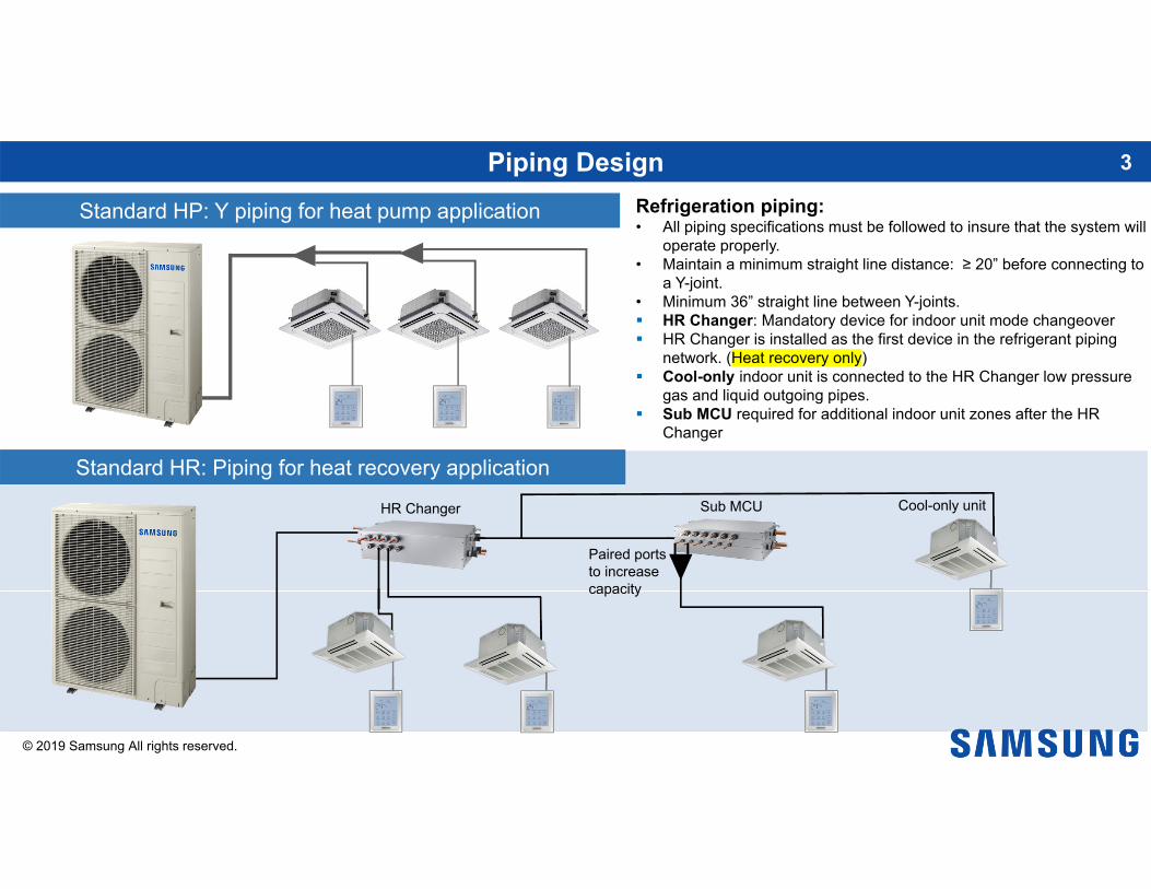
Standard HP: Y piping for heat pump application Refrigeration piping:• All piping specifications must be followed to insure that the system will
operate properly.• Maintain a minimum straight line distance: ≥ 20” before connecting to
a Y-joint.• Minimum 36” straight line between Y-joints. HR Changer: Mandatory device for indoor unit mode changeover HR Changer is installed as the first device in the refrigerant piping
network. (Heat recovery only) Cool-only indoor unit is connected to the HR Changer low pressure
gas and liquid outgoing pipes. Sub MCU required for additional indoor unit zones after the HR
Changer
Standard HR: Piping for heat recovery applicationSub MCUHR Changer Cool-only unit
Defrost mode can start after 30 minutes of heat operation run time, and the suction temperature at the outdoor unit heat exchanger is less than 23°F, or there is a significant temperature difference between the heat exchanger suction gas and ambient.
For installations with high humidity which creates too many defrost cycles, defrost interval can be changed to LOW1 or LOW2 (K5 K6)
Heating capacity is reduced in this operation
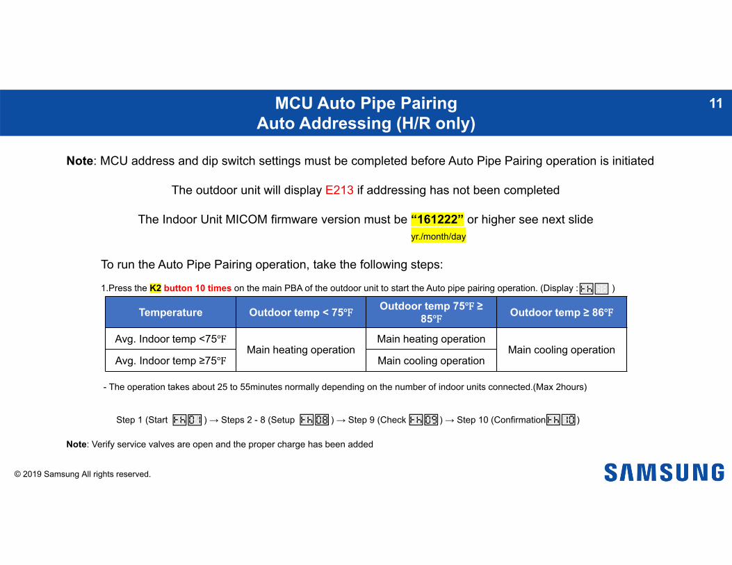
Outdoor Unit Option Settings – Defrost Interval Adjustment 9
1. Press and hold K2 to enter the option setting.(system must be thermo-off) -display will show as follows:
SEG 1, 2 SEG 3, 4
-SEG 1 & 2 will display the number of the optional setting.-SEG 3 & 4 will display the number of set value for the function setting.
2. Shortly press the K1 button to adjust the value of SEG 1 & 2 to match the desired option number.
-Example:
SEG 3, 4SEG 1, 2 SEG 3, 4SEG 1, 2
Quickly pressing K1 button One time.
SEG 3, 4SEG 1, 2 SEG 3, 4SEG 1, 2
Quickly pressing K2 button One time.
3. Shortly press the K2 button to adjust the value of SEG 3 & 4 to match the desired option number.
-Example:
4. After setting the number values in SEG 1, 2, 3 & 4 for the function option you want to change. Press and hold the K2 button for 2 seconds or more to save.
5. All Segments will BLINK and begin tracking
NOTE:• Press and hold the
K1 button to reset values to previous settings.
• Press and hold K4 to restore to factory default settings.
• Once you release K4 for factory default wait until the system resets and starts the tracking process. Then press and hold the K2 button to save the setting.
• Press and hold K4 to restore to factory default settings.
• Once you release K4 for factory default wait until the system resets and starts the tracking process. Then press and hold the K2 button to save the setting.
Optionitem Input unit SEG1 SEG2 SEG3 SEG4 Function Remarks
Heating Correction
Main & SubPCB 0 2
0 0 Default435 (PSI)
Target High Pressure (PSI)
(When low
pressure value is set, discharge air tem
perature of indoor unit will decrease).
0 1 362 (PSI)
0 2 377 (PSI)
0 3 391 (PSI)
0 4 406 (PSI)
0 5 420 (PSI)
0 6 449 (PSI)
0 7 464 (PSI)
0 8 478 (PSI)
Outdoor Setting
14
NOTE:• Press and hold the
K1 button to reset values to previous settings.
• Press and hold K4 to restore to factory default settings.
• Once you release K4 for factory default wait until the system resets and starts the tracking process. Then press and hold the K2 button to save the setting.
When restriction option is set, cooling and heating
performance m
ay decrease.0 1 95%
0 2 90%
0 3 85%
0 4 80%
0 5 75%
0 6 70%
0 7 65%
0 8 60%
0 9 55%
1 0 50%
1 1 No restriction
Outdoor Setting
15
NOTE:• Press and hold the
K1 button to reset values to previous settings.
• Press and hold K4 to restore to factory default settings.
• Once you release K4 for factory default wait until the system resets and starts the tracking process. Then press and hold the K2 button to save the setting.
id area.(near lakes, rivers etc.).0 1 High humidity
Outdoor Fan Speed
Main &
SubPCB
0 6
0 0 Default
Changing this setting w
ill increase fan
speed to m
aximum
value.
0 1 Increase fan speed
Outdoor Setting
16
NOTE:• Press and hold the
K1 button to reset values to previous settings.
• Press and hold K4 to restore to factory default settings.
• Once you release K4 for factory default wait until the system resets and starts the tracking process. Then press and hold the K2 button to save the setting.
contact for both heating and cooling. 0 1 Level 1 /
Auto
0 2 Level 2 / Auto
0 3 Level 3 / Auto
0 4Level 1 External contact
0 5Level 2 External Contact
0 6Level 3 External contact
Outdoor Setting
17
NOTE:• Press and hold the
K1 button to reset values to previous settings.
• Press and hold K4 to restore to factory default settings.
• Once you release K4 for factory default wait until the system resets and starts the tracking process. Then press and hold the K2 button to save the setting.
• Press and hold K4 to restore to factory default settings.
• Once you release K4 for factory default wait until the system resets and starts the tracking process. Then press and hold the K2 button to save the setting.
Option item Input unit SEG1 SEG2 SEG3 SEG4 Function Remarks
Energy savingsmode
MainPCB 1 0
0 0 Disable Default
0 1 Energy saving mode
Energy saving triggers when
the room tem
perature reaches desired set-point
(Heating m
ode only).
0 2 Rapid Cooling
Increase cooling speed.
Outdoor Setting
19
NOTE:• Press and hold the
K1 button to reset values to previous settings.
• Press and hold K4 to restore to factory default settings.
• Once you release K4 for factory default wait until the system resets and starts the tracking process. Then press and hold the K2 button to save the setting.
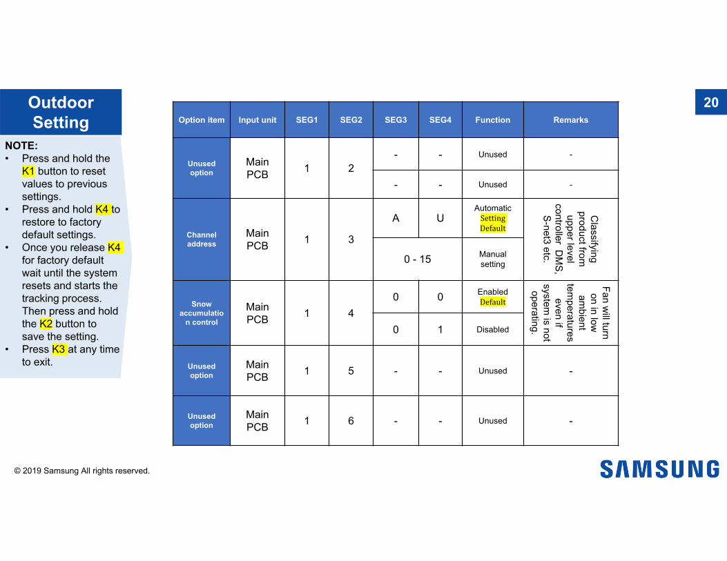
Option item Input unit SEG1 SEG2 SEG3 SEG4 Function Remarks
Unusedoption
Main PCB 1 2
- - Unused -
- - Unused -
Channel address
MainPCB 1 3
A UAutomatic
Setting Default
Classifying
product from
upper level controller D
MS,
S-net3 etc.0 - 15 Manual setting
Snow accumulatio
n control
MainPCB 1 4
0 0 Enabled Default
Fan will turn
on in low
ambient
temperatures even if
system is not
operating.0 1 Disabled
Unusedoption
MainPCB 1 5 - - Unused -
Unusedoption
MainPCB 1 6 - - Unused -
Outdoor Setting
20
NOTE:• Press and hold the
K1 button to reset values to previous settings.
• Press and hold K4 to restore to factory default settings.
• Once you release K4 for factory default wait until the system resets and starts the tracking process. Then press and hold the K2 button to save the setting.
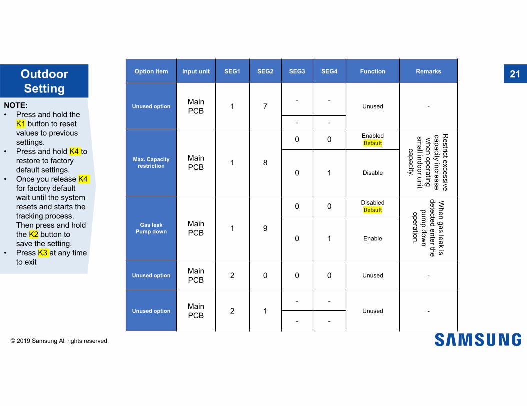
Option item Input unit SEG1 SEG2 SEG3 SEG4 Function Remarks
Unused option MainPCB 1 7
- -Unused -
- -
Max. Capacity restriction
MainPCB 1 8
0 0 Enabled Default
Restrict excessive
capacity increase w
hen operating sm
all indoor unit capacity.0 1 Disable
Gas leak Pump down
MainPCB 1 9
0 0 Disabled Default
When gas leak is
detected enter the pum
p down
operation. 0 1 Enable
Unused option Main PCB 2 0 0 0 Unused -
Unused option Main PCB 2 1
- -Unused -
- -
Outdoor Setting
21
NOTE:• Press and hold the
K1 button to reset values to previous settings.
• Press and hold K4 to restore to factory default settings.
• Once you release K4 for factory default wait until the system resets and starts the tracking process. Then press and hold the K2 button to save the setting.
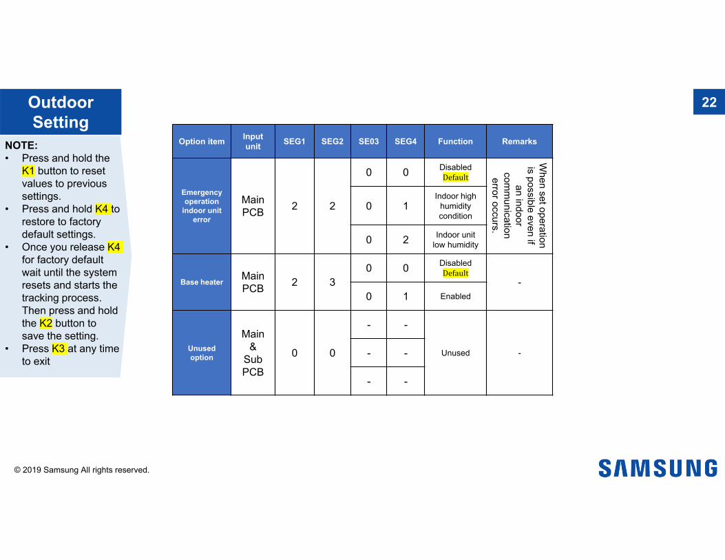
Option item Input unit SEG1 SEG2 SE03 SEG4 Function Remarks
Emergency operation
indoor unit error
Main PCB 2 2
0 0 Disabled Default
When set operation
is possible even if an indoor
comm
unication error occurs.
0 1Indoor high
humidity condition
0 2 Indoor unit low humidity
Base heater Main PCB 2 3
0 0 Disabled Default
-0 1 Enabled
Unused option
Main &
SubPCB
0 0
- -
Unused -- -
- -
Outdoor Setting
22
NOTE:• Press and hold the
K1 button to reset values to previous settings.
• Press and hold K4 to restore to factory default settings.
• Once you release K4 for factory default wait until the system resets and starts the tracking process. Then press and hold the K2 button to save the setting.