CE Eco ICID LIT DOC/CP3/59 July 2014 125 - 200mm Internal Diameter Twin Wall Insulated Chimney System for gas, oil, wood and multi-fuel applications ECO ICID INSTALLATION INSTRUCTIONS Part of the BRAAS MONIER BUILDING GROUP
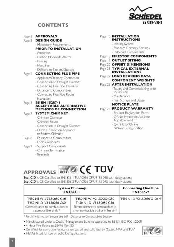
APPROVALSEco ICID is CE Certified to EN1856-1 TÜV 0036 CPR 9195 010 with designations:Eco ICID is CE Certified to EN1856-2 TÜV 0036 CPR 9195 042 with designations:
System ChimneyEN1856-1
Connecting Flue Pipe EN1856-2
T450 N1 W V2 L50050 G60T450 N1 D V3 L50050 G60
60mm distance to combustibles ina combustible shaft *
T450 N1 W V2 L50050 G50T450 N1 D V3 L50050 G50
50mm distance to combustibles ina non combustible shaft or in free air *
T450 N1 D V2 L50050 G100 M
* For full information please see p.8 - Distance to Combustibles Section
• Manufactured under a Quality Management Scheme approved to BS EN ISO 9001: 2008• 4 Hour Fire Rating to BS476 Part 20• Certified for corrosion resistance on gas, oil and solid fuel by Gastec, MPA and TÜV• HETAS listed for use on solid fuel applications.
INSTALLATION INSTRUCTIONS- Jointing System- Standard Chimney Sections- Individual ComponentsFIRESTOP COMPONENTSOUTLET SITINGOFFSET DIMENSIONSTYPICAL EXTERNAL INSTALLATIONSLOAD BEARING DATACOMPONENT WEIGHTSAFTER INSTALLATION- Testing and Commissioning prior to first use- Maintenance- Fuel Storage and UsageNOTICE PLATEPRODUCT WARRANTY- Product Registration Form- QR for Installation Assistant App download- QR link for Online Warranty Registration
APPROVALSDESIGN GUIDE- Mandatory RequirementsPRIOR TO INSTALLATION- Ventilation- Carbon Monoxide Alarms- Painting- Handling- Delivery to Site and StorageCONNECTING FLUE PIPE- Appliance/Chimney Connection- Connection to Draught Diverter- Connecting Flue Pipe Diameter- Distance to Combustibles- Connecting Flue Pipe Route- InspectionBS EN 15287-1 ACCEPTABLE ALTERNATIVE METHODS OF CONNECTIONSYSTEM CHIMNEY- Chimney Diameter- Chimney Route- Connection to Draught Diverter- Direct Connection Appliance to System Chimney- Distance to Combustibles- Enclosures/Shafts- Support Components- Chimney Termination- Terminals
Page 2Page 3
Page 4
Page 5
Page 7
Page 8
Page 9
Page 10
Page 13Page 19Page 20Page 21
Page 22
Page 23
Page 24
DESIGN GUIDE
PRIOR TO INSTALLATION
3
Mandatory RequirementsConnection to an appliance which is not connected to the fuel supply, should be carried out by a competent person. We recommend the use of HETAS approved installers for solid fuel applications. If installation is carried out by a non HETAS registered installer, the installation must be certified by a local Building Control inspector. Connection to an appliance that is connected to the fuel supply must be carried out by a Gas Safe (Gas) or OFTEC (Oil) registered installer.
The design guide must be read in conjunction with the detailed component installation instructions. For full design and installation details the key referral documents are:
•BSEN1856-1: Chimneys - System Chimney Products•BSEN1856-2: Connecting Flue Pipes•BSEN1859: Metal Chimneys - Testing Methods•BSEN1443: Chimneys - General Requirements•BSEN15287-1: Chimneys. Design, installation and commissioning of chimneys. Chimneys for non-room sealed heating appliances.•BS5440-1: Fluing and ventilation for gas appliances of rated input not exceeding 70kW net (1st, 2nd and 3rd family gases). Specification for installation of gas appliances to chimneys and for maintenance of chimneys.•ApprovedDocumentJ: - Combustion appliances and fuel storage systems (England & Wales)•DFPTechnicalBookletL: - Combustion appliances and fuel storage systems (NI)•TechnicalHandbook(Domestic&NonDomestic),Section3 - Environment (Scotland)•ApplianceInstallationInstructions and related standards. Other standards covering specific applications will also be relevant and must be adhered to.
Planning permission may be required, and reference should be made to the local Building Control Department.
Ensure all chimney components are available and check them to ensure there has been no damage. Do not use damaged components. Build the chimney up through the previous designed route which should be as straight as possible.
VentilationIt is very important that sufficient air for combustion and ventilation is provided to the room containing the appliance, to enable correct and efficient working of the appliance and chimney system. Reference should be made to the appliance manufacturer’s instructions and recommendations are also given in the Building Regulations Document J, CIBSE guidance notes and BS 5440.
CarbonMonoxideAlarmsThe carbon monoxide alarms should comply with BS EN 50291
Where a new or replacement fixed solid fuel appliance is installed in a dwelling, a carbon monoxide alarm must be provided in the room where the appliance is located.Please follow manufacturers instructions with regards to siting and fixing or alternatively :-a) On the ceiling at least 300mm from any wall or if it is located on a wall, as high up as possible (above any doors and windows), but not within 150mm of the ceiling andb) between 1m and 3m horizontally from the appliance.
N.B Provision of a carbon monoxide alarm should not be regarded as a substitute for correct installation and regular servicing.
PaintingIf painting of any external sections is required, it is important to de-grease, dry and prime the exterior surface prior to the application of appropriate heat resistant paint. Schiedel Chimney Systems can provide to special order, chimney sections and accessories painted to an extensive range of British Standard RAL colours – details on application.
HandlingIt is advised that suitable PPE should be used when handling the products.
DeliverytoSiteandStorageComponents should be carefully transported and off loaded. They should be inspected to ensure they have not been damaged, and should be stored off the ground and under cover so that they are protected from accidental damage and the adverse effects of weather.
Appliance/Chimney ConnectionConnection to the appliance can be made using Prima Smooth, Prima Plus or alternative approved single wall connecting flue pipes, or Eco ICID.
This must be done by using the appropriate appliance connector. When a single wall connecting flue pipe is used to connect an appliance to the chimney, the lower end of the chimney section must extend a minimum of 425mm below the ceiling. When connecting the appliance to the flue pipe all joints between the flue pipe/appliance outlet must be securely caulked and sealed with non asbestos rope (or suitable alternative) and fire cement on solid fuel appliances.
Any flue pipe connection to the chimney MUST be made in the same room as the appliance.
ConnectiontoDraughtDiverterWhere the appliance features a draught diverter the connection should rise vertically from it for at least 600mm before any change of direction (unless otherwise specified by the appliance manufacturer). This is in accordance with the recommendations contained in BS 5440 Part 1 section 6.1.4
Connecting Flue Pipe Diameter Connecting Flue Pipe Diameter size should be as recommended by the appliance manufacturer. Under all circumstances the operational requirements of the appliance and the configuration of the flue must satisfy the flue sizing requirements of EN13384-1.
DistancetoCombustiblesIn accordance with building regulations, it is essential that the correct distance to combustible material is maintained on connecting flue pipes. On solid fuel applications, where there is a risk of soot fire, on unmeasured (NM) designated single wall product, this distance is 3 x ØInt of the pipe, e.g. for Ø125mm the distance is 375mm and for Ø150mm the distance is 450mm to combustibles on both painted and non painted variants. On measured (M) single wall or double wall products this distance will be as declared by the chimney manufacturer. On Eco ICID this distance has been measured and is set at 100mm.
Connecting Flue Pipe RouteSingle wall connecting flue pipes should only be used to connect appliances to a Chimney. They should not pass through any roof space, partition, internal wall or floor, except to pass directly into a chimney through a wall of the chimney.
Connecting flue pipes should be located as to avoid igniting combustible material.
On solid fuel appliances the maximum length of a connecting flue pipe is 2m. This distance is reduced to 1.5m if any of the acceptable alternative methods of connection are adopted as per BS EN15287-1. (See p.5-6 for full details.)
On appliances with a top outlet, it is recommended that a vertical run of at least 600mm should be allowed immediately above the appliance prior to any change of direction.
On appliances with a rear outlet, it is recommended that there is maximum of 150mm in the horizontal run however under certain conditions, as described in alternative methods in BS EN 15287-1, this may be increased to 450mm. (See p.5-6 for full details.)
Within a system (Chimney + Connecting Flue Pipe) there should be no more than 4 changes of direction of maximum 45˚. 90˚ Factory made bends or tees within the system may be treated as being equal to two 45˚ bends (as per Document J of the Building Regulations issued October 2010).
InspectionOn solid fuel applications to conform to Building Regulations, provisions should be made to enable a chimney to be inspected and cleaned.
An inspection pipe, inspection elbow or a 90° or 135° Tee with tee cap can form a suitable inspection point (unless cleaning/inspection can be done through the appliance). To aid cleaning, sufficient distance should be left between changes of direction to permit the safe passage of cleaning brushes within the system. This is particularly important on solid fuel applications. It is recommended that chimneys serving solid fuel appliances be swept as frequently as necessary, but at least twice a year.
4
CONNECTING FLUE PIPE
5
BS EN 15287-1ACCEPTABLE ALTERNATIVE METHODS OF CONNECTION
Where a horizontal connecting flue of more than 150mm is required to connect a solid fuel fired appliance to a chimney, an installation method as per the examples below may be used provided the following criteria is met:-
Top Outlet Single Wall Connecting Flue Pipe through Solid Wall into Twin Wall System Chimney
NB Where the connecting flue pipe from the appliance passes through any wall other than the existing chimney wall, the connecting flue pipe must be a System Chimney of twin wall insulated design.
Top Outlet Twin Wall Connecting Flue Pipe through Solid Wall into Twin Wall System Chimney
For minimum distance for this configuration check manufacturers distanceto combustibles
Measured from back of appliance to outside surface of chimney
Measured from back of appliance to liner of masonry chimney
Twin Wall Chimney System
300
Wall Support
Tee Cap forDebris Collection/Cleaning Access
Wall Sleeve
Trim Collar
Cavity Wall Wall Band
450mm MAX300
450mm MAX
External Masonry Chimney System
Inspection/Cleanout Door
Cavity Wall
Wall Sleeve
Trim Collar
DebrisCollector
Wall Sleeve
Trim Collar
100100
225 square(9” x 9”)
Flexible Twin Wall Chimney Liner
Chimney Wall
Support Bracket
Swept Elbow
Sweep access
Tee Piece
Single Wall to Flex Connector
450mmMAX
Measured from back of appliance to flue liner
Wall Support
Measured from back of connecting flue pipe to outside surface of chimney
Tee Cap forDebris Collection/Cleaning Access
Twin Wall Chimney System
Solid Wall
Inspection Bend
Wall Sleeve
Trim Collar
600 min
225For minimum distance for this configuration check manufacturers distanceto combustibles
No further bends allowed on this configeration
Wall Band
450mm MAX
Measured from back of connecting flue pipe to outside surface of chimney
Tee Cap forDebris Collection/Cleaning Access
Twin Wall Chimney System
Solid Wall
Inspection Bend
Wall Sleeve
Trim Collar
225
Wall Support
Wall Band
450mm MAX
600 min
For minimum distance for this configuration check manufacturers distanceto combustibles
No further bends allowed on this configeration
Flexible Twin Wall Chimney Liner
Inspection/Cleanout Door
Inspection Bend
Wall SleeveTrim Collar
Chimney Wall
Support Bracket
Tee Piece
Tee Cap forDebris Collection/Cleaning Access
Single Wall to Flex Connector
225 square(9” x 9”)
450mmMAX
For minimum distance for this configuration check manufacturers distanceto combustibles
For minimum distance for this configuration check manufacturers distanceto combustibles
For minimum distance for this configuration check manufacturers distanceto combustibles
Measured from back of connecting flue pipe to flue liner
No further bends allowed on this configeration
600 min
100100
6
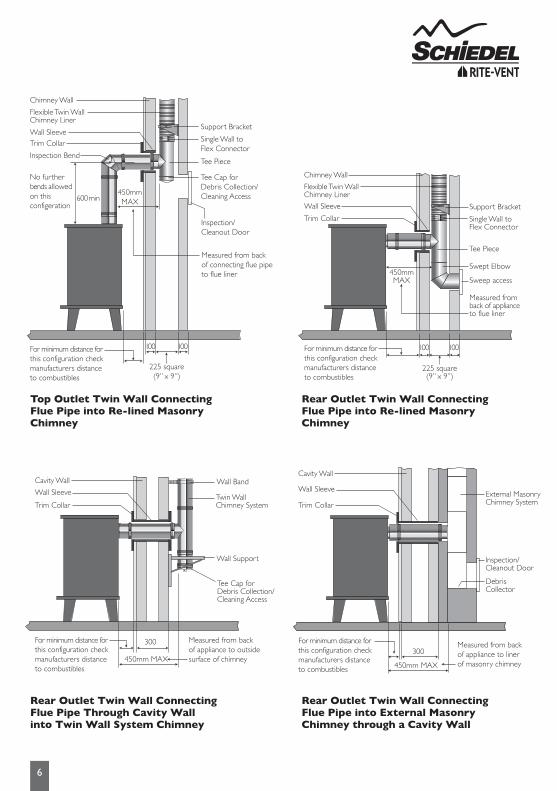
Top Outlet Twin Wall Connecting Flue Pipe into Re-lined Masonry Chimney
Rear Outlet Twin Wall Connecting FluePipeThroughCavityWallinto Twin Wall System Chimney
For minimum distance for this configuration check manufacturers distanceto combustibles
Measured from back of appliance to outside surface of chimney
Measured from back of appliance to liner of masonry chimney
Twin Wall Chimney System
300
Wall Support
Tee Cap forDebris Collection/Cleaning Access
Wall Sleeve
Trim Collar
Cavity Wall Wall Band
450mm MAX300
450mm MAX
External Masonry Chimney System
Inspection/Cleanout Door
Cavity Wall
Wall Sleeve
Trim Collar
DebrisCollector
Wall Sleeve
Trim Collar
100100
225 square(9” x 9”)
Flexible Twin Wall Chimney Liner
Chimney Wall
Support Bracket
Swept Elbow
Sweep access
Tee Piece
Single Wall to Flex Connector
450mmMAX
Measured from back of appliance to flue liner
Wall Support
Measured from back of connecting flue pipe to outside surface of chimney
Tee Cap forDebris Collection/Cleaning Access
Twin Wall Chimney System
Solid Wall
Inspection Bend
Wall Sleeve
Trim Collar
600 min
225For minimum distance for this configuration check manufacturers distanceto combustibles
No further bends allowed on this configeration
Wall Band
450mm MAX
Measured from back of connecting flue pipe to outside surface of chimney
Tee Cap forDebris Collection/Cleaning Access
Twin Wall Chimney System
Solid Wall
Inspection Bend
Wall Sleeve
Trim Collar
225
Wall Support
Wall Band
450mm MAX
600 min
For minimum distance for this configuration check manufacturers distanceto combustibles
No further bends allowed on this configeration
Flexible Twin Wall Chimney Liner
Inspection/Cleanout Door
Inspection Bend
Wall SleeveTrim Collar
Chimney Wall
Support Bracket
Tee Piece
Tee Cap forDebris Collection/Cleaning Access
Single Wall to Flex Connector
225 square(9” x 9”)
450mmMAX
For minimum distance for this configuration check manufacturers distanceto combustibles
For minimum distance for this configuration check manufacturers distanceto combustibles
For minimum distance for this configuration check manufacturers distanceto combustibles
Measured from back of connecting flue pipe to flue liner
No further bends allowed on this configeration
600 min
100100
For minimum distance for this configuration check manufacturers distanceto combustibles
Measured from back of appliance to outside surface of chimney
Measured from back of appliance to liner of masonry chimney
Twin Wall Chimney System
300
Wall Support
Tee Cap forDebris Collection/Cleaning Access
Wall Sleeve
Trim Collar
Cavity Wall Wall Band
450mm MAX300
450mm MAX
External Masonry Chimney System
Inspection/Cleanout Door
Cavity Wall
Wall Sleeve
Trim Collar
DebrisCollector
Wall Sleeve
Trim Collar
100100
225 square(9” x 9”)
Flexible Twin Wall Chimney Liner
Chimney Wall
Support Bracket
Swept Elbow
Sweep access
Tee Piece
Single Wall to Flex Connector
450mmMAX
Measured from back of appliance to flue liner
Wall Support
Measured from back of connecting flue pipe to outside surface of chimney
Tee Cap forDebris Collection/Cleaning Access
Twin Wall Chimney System
Solid Wall
Inspection Bend
Wall Sleeve
Trim Collar
600 min
225For minimum distance for this configuration check manufacturers distanceto combustibles
No further bends allowed on this configeration
Wall Band
450mm MAX
Measured from back of connecting flue pipe to outside surface of chimney
Tee Cap forDebris Collection/Cleaning Access
Twin Wall Chimney System
Solid Wall
Inspection Bend
Wall Sleeve
Trim Collar
225
Wall Support
Wall Band
450mm MAX
600 min
For minimum distance for this configuration check manufacturers distanceto combustibles
No further bends allowed on this configeration
Flexible Twin Wall Chimney Liner
Inspection/Cleanout Door
Inspection Bend
Wall SleeveTrim Collar
Chimney Wall
Support Bracket
Tee Piece
Tee Cap forDebris Collection/Cleaning Access
Single Wall to Flex Connector
225 square(9” x 9”)
450mmMAX
For minimum distance for this configuration check manufacturers distanceto combustibles
For minimum distance for this configuration check manufacturers distanceto combustibles
For minimum distance for this configuration check manufacturers distanceto combustibles
Measured from back of connecting flue pipe to flue liner
No further bends allowed on this configeration
600 min
100100
7
SYSTEM CHIMNEY
Chimney DiameterThe chimney size should be as recommended by the appliance manufacturer. Where there is a requirement for a flue diameter smaller than the appliance spigot, then the operational requirements of the appliance and the configuration ofthe flue must satisfy the flue sizing requirements of EN13384-1 for single appliances, and EN13384-2 for multi appliances.
Chimney RouteThe chimney should remain as straight as possible through its vertical run to assist flow. Should it be necessary to offset a chimney run then the following guidelines should be adhered to:
It is recommended that a vertical run of at least 600mm should be allowed immediately above the appliance prior to any change of direction. Within a system, on all fuels, there should be no more than 4 changes of direction of maximum 45°. Factory made 90° bends or tees within the system may be treated as being equal to two 45° bends (as per Document J of the Building Regulations issued October 2010).
ConnectiontoDraughtDiverterWhere the appliance features a draught diverter the connection should rise vertically from it for at least 600mm before any change of direction (unless otherwise specified by the appliance manufacturer). This is in accordance with the recommendations contained in BS 5440 Part 1 section 6.1.4
Direct Connection Appliance to System ChimneyWhen connecting from the appliance directly to a system chimney, the appropriate appliance connector must be used and the joint between the appliance spigot and the appliance connector must be securely caulked and sealed with non asbestos rope (or suitable alternative) and fire cement on solid fuel appliances.
Eco ICID direct connection from appliance.
8
DistancetoCombustiblesIn accordance with building regulations, it is essential that the correct distance to combustible material is maintained. On solid fuel applications, where there is a risk of soot fire, a distance of 60mmtocombustibles must be maintained within a combustiblefloor and within a combustibleshaft (see Fig.1 below).There is no need to line the area within the floor cavity with plasterboard; however the ventilatedfirestopplate andventilatedsupport plate must be used.
On gas and oil applications, a distance of 50mmtocombustibles must be maintained within a combustiblefloor and within a combustibleshaft. The ventilatedfirestopplate and ventilatedsupportplate must be used.
Where the chimney penetrates a non combustible floor and where a non combustible shaft is used, a distance of 50mmtotheshaft is sufficient. In this case, nonventilatedfirestopplatesandsupportplates may be used with a ventilatedfirestop being used where the chimney penetrates into the roof space.
On bungalow applications where the chimney runs through either a combustible or non-combustible ceiling, an unventilated bungalow fire stop plate kit can be used. Please note that an unventilated support plate can not be used above the ceiling in this case. The weight of the chimney should be supported using the roof support (see p.17). Distance to combustibles must be respected within the ceiling space (see Fig. 2 below) and mesh frame should be used within the loft space, which must be ventilated (see Fig. 2 below).
Enclosure/ShaftsWith the exception of the room containing the appliance, where the chimney passes through any part of the building, where there is a risk of accidental human contact, i.e a bedroom etc., or where there is a risk of contact with combustible materials stored in a cupboard or in the roof-space, the chimney must be enclosed in an appropriate way to meet Building Regulations. This can be achieved by boxing in the chimney in habitable rooms, or by the use of a protective wire mesh frame in roof spaces etc. In all cases the minimum distance to any combustible material, including loft insulation, must be respected according to the table on p.1, and any enclosure should be ventilated using the appropriate ventilated fire stops (see p.13).
Fig. 1 Fig. 2
Internal HouseCombustible Floors
InternalBungalow(VentilatedLoftSpace)Combustible and Non-Combustible Floors
9
Support ComponentsThe weight of a chimney system is considerable and requires independent support. Minimal weight should be borne by the appliance. The weight of the chimney can be supported from floor level by using a base support plate, or floor support; from the wall by using wall support top plates together with side plates or cantilever brackets; or from first floor level by using a support plate and clamp fixed to the floor/ceiling joists.
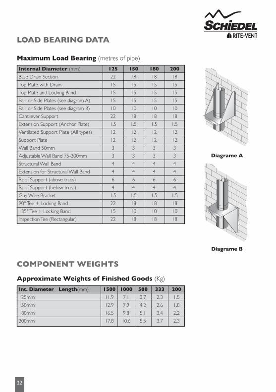
Wall brackets are non load bearing and provide lateral support only. Refer to the load bearing tables on page 22 for full details of maximum loadings.
Where the flue is freestanding above the roof and its height exceeds 1.5m above the last support or above the roof, a height of up to 3m can be achieved unsupported using the extended locking bands at the joint immediately below the last support and on each pipe joint above the last support.
Alternatively guy wire brackets can be used at the 1.5m level and every 1.5m thereafter in conjunction with guy wires, or rigid stays (provided by others).
Chimney TerminationFor full information regarding to chimney termination, please refer to Annex M of BS EN 15287-1. As a guide please refer to page 19 of these installation instructions.
TerminalsAll terminals must be secured with the use of a locking band. On solid fuel appliances, an open termination is normally recommended. However in certain conditions, rain caps or anti-downdraught terminals may be used.
Rain caps and anti-downdraught terminals are available in three versions, with anti-bird mesh, with spark guard, or without mesh. Where a terminal with mesh is used, there is a risk of soot build up, and therefore regular cleaning is required to avoid blockage, particularly when using oil or solid fuel.
10
INSTALLATION INSTRUCTIONS
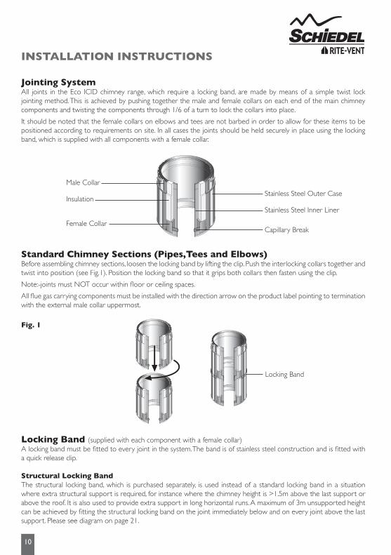
JointingSystemAll joints in the Eco ICID chimney range, which require a locking band, are made by means of a simple twist lock jointing method. This is achieved by pushing together the male and female collars on each end of the main chimney components and twisting the components through 1/6 of a turn to lock the collars into place.
It should be noted that the female collars on elbows and tees are not barbed in order to allow for these items to be positioned according to requirements on site. In all cases the joints should be held securely in place using the locking band, which is supplied with all components with a female collar.
StandardChimneySections(Pipes,TeesandElbows)Before assembling chimney sections, loosen the locking band by lifting the clip. Push the interlocking collars together and twist into position (see Fig.1). Position the locking band so that it grips both collars then fasten using the clip.
Note:-joints must NOT occur within floor or ceiling spaces.
All flue gas carrying components must be installed with the direction arrow on the product label pointing to termination with the external male collar uppermost.
LockingBand(supplied with each component with a female collar)A locking band must be fitted to every joint in the system. The band is of stainless steel construction and is fitted with a quick release clip.
StructuralLockingBandThe structural locking band, which is purchased separately, is used instead of a standard locking band in a situation where extra structural support is required, for instance where the chimney height is >1.5m above the last support or above the roof. It is also used to provide extra support in long horizontal runs. A maximum of 3m unsupported height can be achieved by fitting the structural locking band on the joint immediately below and on every joint above the last support. Please see diagram on page 21.
Fig. 1
Locking Band
Stainless Steel Outer Case
Male Collar
Stainless Steel Inner Liner
Insulation
Capillary BreakFemale Collar
11
AdaptorsfromPrimaPlus&PrimaSmoothtoEcoICIDThese components are used to convert from a single wall connecting flue pipe to the Eco ICID system chimney. The protruding liner should be pushed down inside the female socket of the connecting flue pipe, with the male collar pointing upwards.
AdaptortoFlex/TecnoFlexPlusThis component is used to convert from Eco ICID to Flex/TecnoFlex Plus.The Flex/TecnoFlex Plus is pushed down inside the upstand on the adaptor, secured using self tapping screws and sealed with fire cement and fire rope to provide a gas tight joint.
Adaptor from Eco ICID to Prima PlusThis component is manufactured with an Eco ICID female collar and a Prima Plus female socket, and is used wherethere is a requirement to convert from Eco ICID to Prima Plus.The Eco ICID female collar should be attached tothe previous Eco ICID component and the joint secured using the locking band provided.
IncreaserThis component is used to increase from one diameter to the next diameter (e.g.) 125mm to 150mm.The component is fitted in the same way as a standard pipe length and should be secured with the locking band provided.
Elbowsand90°InspectionElbowsFor offset information on standard elbows, please refer to p.20Please note that 90° Inspection bends may be incorporated into a connecting flue pipe arrangement on all fuels, please refer to National Annex of BS EN 15387-1 for specific guidance re use on solid fuel applications.In cases of top mounted stoves, a minimum vertical height of 600mm from the appliance is recommended prior to any change of direction in the flue pipe.
SW-DWStovePipeStarterSectionThis component is used to connect from a vitreous enamel or stainless steel single wall connecting flue pipe to Eco ICID. The protruding liner should be pushed down inside the female socket of the connecting flue pipe and the joint sealed with fire cement or high temperature sealant to provide a gas tight joint.
Please note that when a single wall connecting flue pipe is used to connect to the starter section, the joint between these two components must be a minimum of 425mm below the ceiling in accordance with BS EN 15287-1.
SW-DWAdjustableStarterSectionThe protruding male spigot of the adaptor slides down inside the female socket of the Prima Smooth pipe and the socket of the Prima Smooth pipe slides within the conical section of the starter adaptor, to a maximum length of 75mm into the cone with a minimum of 15mm to ensure a secure connection. This maximum length of 75mm will leave sufficient space within the adaptor to allow for thermal expansion of the single wall pipe and also to allow for the connecting flue pipe to be removed without cutting, if the appliance has to be moved for servicing.
Appliance Connector
SW-DWStovePipeStarter Section
Male Collar
Protuding Liner
Appliance Connector1.
2.
The protruding liner of these components should be pushed into the appliance spigot with the male collar pointing upwards.
On solid fuel appliances the appliance connector should be sealed to the appliance with fire rope and fire cement or high temperature sealant to provide a gas tight joint.
100
15 minPrimaSmooth
SW-DWAdjustableStarterSection
75 max
12
Anchor PlateWhen commencing an installation with a fire chest, or when extending an existing brick or masonry chimney stack, an anchor plate must be used. The liner of the Anchor Plate should be pushed into the opening of the fire chest with the plate resting on a bed of fire cement. The plate should then be fixed onto the concrete slab by masonry screws fitted through the pre-drilled holes in the plate. In the case of a chimney extension, the liner of the anchor plate fits down inside the existing chimney stack, or if a chimney liner has been used, inside the chimney liner, to which it should be secured using self tapping screws and sealed with fire cement and fire rope. The plate should then be then be fixed to the top of the existing chimney and sealed using fire cement.
InspectionLength(DrySystems)The inspection length is a component providing the facility for flue inspection and cleaning. It is installed as per a standard pipe section.
90°TeeThis component may be used to connect from a connecting flue pipe to the vertical system chimney at 90° or the branch may be used to locate a draft stabiliser. It is installed as per a standard pipe section. Please note that there are no barbs on the female collar in order to allow for the tee to be positioned at the correct angle. It is supplied complete with a locking plug.
135°TeeThis component may be used in combination with a 45° elbow to connect from aconnecting flue pipe to the vertical system chimney. It is installed as per a standard pipe section and provides the least resistance to the flow of the flue gases. Please note that there are no barbs on the female collar in order to allow for the tee to be positioned at the correct angle. It is supplied complete with a locking plug.
AdjustablePipe/TelescopicPipesThey are used with standard components to achieve an exact length on site and avoid on-site cutting of components.
1. Calculate the length required.2. Remove insulation as required to achieve the correct length.3. Fix the adjusted section to standard components using the locking band provided.
Please note that the adjustable pipe is non load bearing.
Anchor Plate
Inspection Length (DrySystems)
AdjustablePipe
(50-230mm)
Telescopic Pipe
a)215-310mmb)350-570mm
90˚Tee
135˚Tee
Int ØExt ØA (mm)
B (mm)
125180246127
150200329162
180235354175
200256394195
Int ØExt ØA (mm)
B (mm)
C (mm)
125180336259259
150200365283283
180235414326326
200256444351351
EffectiveLength460mm
Int ØExt Ø
A
B
BInt
ØEx
t Ø90˚
Int ØExt Ø
A
B
C
Int Ø
Ext Ø
135˚
13
1.
2.3.4.
5.
Frame a four sided level square opening within the joists using timber stringers where necessary to allow for the correct distance to combustibles from the outer wall of the chimney. This distance must be a minimum of 50mm on Gas and Oil applications and 60mm for solid fuel applications (see Fig. 3 below - distance x).Lower the chimney section through the opening in the fl oor, and secure to the next section of pipe.Locate the two halves of the support plates around the chimney section, and secure to the joists using screws or bolts.Remove the self-drilling screws which are fastened to the clamp band.Then fasten clamp band around the chimney section and position on top of the plate. Tighten using the nuts and bolts provided.Using the holes in the clamp band as a guide, fasten the three self-drilling screws to the outer case of the Eco ICID system.Note:JointsmustNOToccurwithinthefloororceilingjoists.
Ventilated Support Plate (Galvanised plate with S/S Band)The support plate is used where the chimney passes through a combustible fl oor, and the weight of the chimney has to be taken at fl oor level. The support plate must be fi rmly fi xed by using bolts or screws. For load bearing Data refer to tables 1 and 2 on page 22.
VentilatedFirestop Plate
VentilatedSupport Plate
FIRESTOP COMPONENTS
Fig. 1 Fig. 2 Fig.3
Ventilated Firestop Plate (1 & 2-Piece Round and 2-Piece Rectangular)The ventilated fi re stop plates are used in combination with standard Eco ICID pipes where the chimney passes through a combustible fl oor or ceiling.The outermost circle of ventilation slots gives a distance to combustibles of 60mm. This measures the required distance for solid fuel applications. For gas and oil applications a minimum of 50mm is required, which should be measured on site.The fi re stop plate should be positioned around the chimney and fastened to the pre-cut plasterboard or to the timber frame with nails or screws using the location holes provided (see Fig. 2 above).
MagneticFirestopCover(Optional)Can be used in combination with 1-piece Ventilated Firestop Plate)
Non-Ventilated Bungalow FirestopInstalled as per a ventilated fi restop using the fi xing holes provided (see Fig.4 above). Distance to combustiblesmust be respected - see p.8 for further info.
Support Plate with S/S Clamp Band (Non Combustible Floor)The support plate is used where the chimney passes through a non combustible fl oor, and the weight of the chimney has to be taken at fl oor level. The support plate must be fi rmly fi xed to the fl oor using bolts or screws provided by others. For Load Bearing Data refer to table on page 22.
Fire stop Plate (Non Combustible Floor)This fi re stop plate is used exclusively where the chimney passes through a non combustible fl oor.The two halves of the plate are located around the chimney section and fastened to the fl oor using bolts or screws provided by others.
Non-Ventilated Bungalow Firestop
Kit Installation In Situ
14
WallBand(60mm)Internal and External ApplicationThe wall band is supplied in three parts, two stainless steel split bands which fit tightly around the outside of the chimney and a stainless steel back bracket.The parts are joined together by means of the nuts and bolts provided.The use of the item maintains a fixed distance of 60mm from the outer casing of the chimney to the wall or fixing point.
AdjustableBackBracket(60-300mm)Internal and External ApplicationThe adjustable wall bracket is supplied in three parts, a ‘U’ shaped stainless steel adjustable section, two bolts for fixing the wall band to the back bracket and a strengthening cross bracket.
Once the position of the support has been determined, secure the back bracket to the wall with a method of fixing to ensure adequate attachment and support.
The stainless steel split band is then positioned around the chimney section and secured with the nuts and bolts provided to the back bracket.
The wall bracket provides lateral stability only, it is NOT load bearing and is to be positioned at 3 metre centres.
1.
2.
3.
Once the position of the support has been determined, secure the U shaped bracket to the wall with a method of fixing to ensure adequate attachment and support.
Determine the amount of extension required and secure the back bracket of the wall band in place onto the adjustable section.
Fasten the strengthening cross bracket in place using the bolts provided.
With the back bracket in place, locate the rear portion of the band onto the back bracket, the outer part of the band is then positioned around the chimney section and secure with the nuts and bolts provided.
The adjustable wall band provides lateral stability only, it is NOT load bearing and is to be positioned at 3 metre centres.
1.
2.
3.
4.
5.
Wall Band(60mm)
AdjustableBackBracket
(60-300mm)
Wall Band andAdjustableBackBracketAssembly
A
B
B
C
Int ØExt ØA (mm)
B (mm)
C (mm)
12518013111225
15020014813225
18023518516225
20025620218625
15
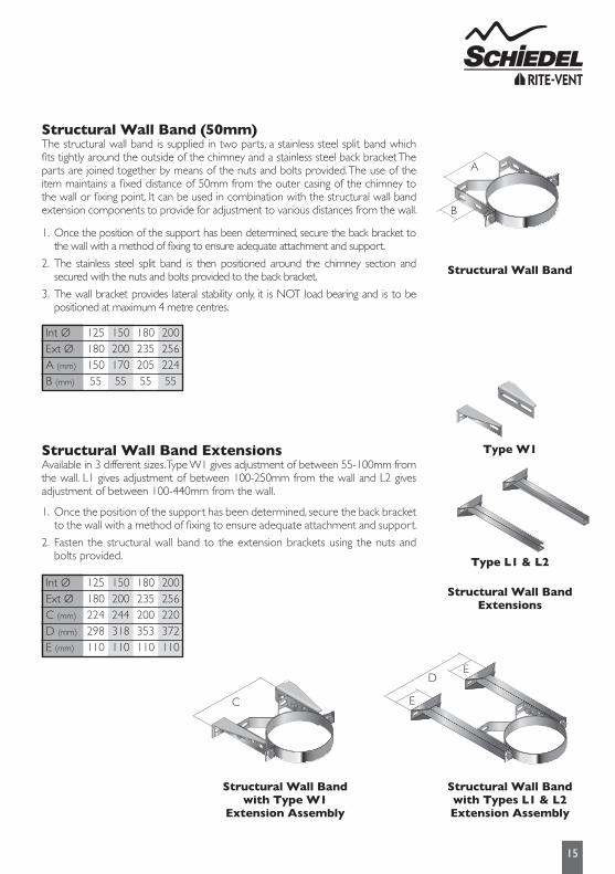
StructuralWallBand(50mm)The structural wall band is supplied in two parts, a stainless steel split band which fits tightly around the outside of the chimney and a stainless steel back bracket The parts are joined together by means of the nuts and bolts provided. The use of the item maintains a fixed distance of 50mm from the outer casing of the chimney to the wall or fixing point. It can be used in combination with the structural wall band extension components to provide for adjustment to various distances from the wall.
StructuralWallBandExtensionsAvailable in 3 different sizes. Type W1 gives adjustment of between 55-100mm from the wall. L1 gives adjustment of between 100-250mm from the wall and L2 gives adjustment of between 100-440mm from the wall.
Once the position of the support has been determined, secure the back bracket to the wall with a method of fixing to ensure adequate attachment and support.
The stainless steel split band is then positioned around the chimney section and secured with the nuts and bolts provided to the back bracket.
The wall bracket provides lateral stability only, it is NOT load bearing and is to be positioned at maximum 4 metre centres.
1.
2.
3.
Once the position of the support has been determined, secure the back bracket to the wall with a method of fixing to ensure adequate attachment and support.
Fasten the structural wall band to the extension brackets using the nuts and bolts provided.
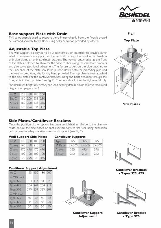
Base support Plate with DrainThis component is used to support the chimney directly from the floor. It should be fastened securely to the floor using bolts or screws provided by others.
AdjustableTopPlateThe wall support is designed to be used internally or externally to provide either initial or intermediate support for the vertical chimney. It is used in combination with side plates or with cantilever brackets. The turned down edge at the front of the plates is slotted to allow for the plate to slide along the cantilever brackets and give some positional adjustment. The female socket on the pipe attached to the underside of the plate should be pushed down onto the preceding pipe and the joint secured using the locking band provided. The top plate is then attached to the side plates or the cantilever brackets using the bolts provided through the fixing slots in the top plate (see Fig. 1). The bolts should then be tightened firmly.
For maximum height of chimney see load bearing details, please refer to tables and diagrams on pages 21-22.
SidePlates/CantileverBracketsOnce the position of the support has been established in relation to the chimney route, secure the side plates or cantilever brackets to the wall using expansion bolts to ensure adequate attachment and support (see Fig. 2).
Fig.1
Top Plate
Side Plates
CantileverSupportAdjustmentInt ØC max (mm)
Type 325Type 475Type 570C min (mm)
Type 325Type 475Type 570
125
134284379
505050
150
114264359
505050
180
84234329
505050
200
64214309
505050
CantileverSupportsTypeØ RangeA (mm)
B (mm)
325125-200
325242
325125-200
475242
325125-200
570242
CantileverBracket-Type570
CantileverSupportAdjustment
CantileverBrackets- Types325,475
A
B
A
B
C
E
D
F
A B
42
C
Int ØExt ØA (mm)
B (mm)
125180280276
150200300296
180235335334
200256356352
Wall Support Side PlatesInt ØC (mm)
D (mm)
E (mm)
F (mm)
125160470100275
150180470100295
180210470100325
200230470100345
17
Roof SupportThe roof support is supplied as a kit complete with two side plates for fixing to the roof trusses, a band to give lateral support to the chimney as it passes through the roof, and 3 self tapping screws, which are secured to the chimney through the band to give a load bearing capacity. When the plates are installed above the roof trusses as in Fig.1 the maximum number of pipes, which may be suspended from the roof support is 6 x 1m pipes. When the plates are attached below the trusses as in Fig.2 the maximum number of pipes, which may be suspended is 4 x 1m pipes.
The band should be lowered down over the top of the Eco ICID pipe, and positioned so that the the side plates are resting on top of the roof trusses as in Fig.1 or below the roof trusses in the case of Fig. 2. The recommended position is always as per Fig.1 where circumstances allow this solution.
The band should then be tightened using the nut and bolt provided.
Using the holes pre-drilled in the roof support band, drill 3mm holes in the outer case of the chimney section (drill bit should be set for a depth no greater than 10mm to avoid any damage to the liner of the chimney)
Use the self tapping screws provided to secure the clamp band to the outer casing of the chimney section.
1.
2.
3.
4.
Please note: It is the responsibility of the installer to ensure that the joist to which the roof support is being attached is load bearing and capable of withstanding the weight of the system being installed.
GuyWireBracketThis component should be used to secure unsupported chimney sections aboveroof level. Guy wires or preferably rigid stays (supplied by others) must be fixed to the bracket and secured to suitable anchorage points to ensure that the chimneysections are stable.
A maximum chimney height of 1.5 metres from the last support, or from the roof is permitted. Additional height requirements MUST be supported at 1.5 metre intervals using the guy wire bracket as specified above.
Ceiling HangerThis accessory is designed to support horizontal runs of the chimney from the roof or ceiling and offers adjustment from 130mm to 1115mm.
Once the position of the ceiling support has been determined, the section length of uni-rax channel must be securely fixed to the roof or the ceiling using a method of attachment to ensure adequate attachment and support.
All items are assembled as shown to attach the length of studding to the channel.
Attach the stud connector to the length of studding and connect the eye bolt to the connector.
Position the split band around the chimney section and secure to the eye bolt using the nut/bolt provided.
Maximum support spacing to be no more than 1.5 metres.
1.
2.
3.
4.
5.
GuyWireBracket
Ceiling Hanger
Guy Wire
Rigid Stay
Fig.1
Fig.2
1.5 metresmaximum
18
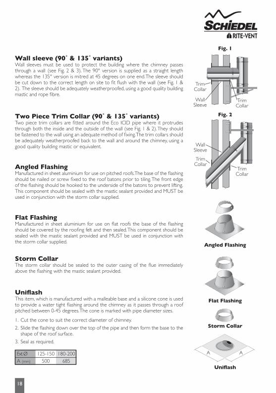
Wallsleeve(90˚&135˚variants)Wall sleeves must be used to protect the building where the chimney passes through a wall (see Fig. 2 & 3). The 90° version is supplied as a straight length whereas the 135° version is mitred at 45 degrees on one end. The sleeve should be cut down to the correct length on site to fit flush with the wall (see Fig. 1 & 2). The sleeve should be adequately weatherproofed, using a good quality building mastic and rope fibre.
TwoPieceTrimCollar(90˚&135˚variants)Two piece trim collars are fitted around the Eco ICID pipe where it protrudes through both the inside and the outside of the wall (see Fig. 1 & 2). They should be fastened to the wall using an adequate method of fixing. The trim collars should be adequately weatherproofed back to the wall and around the chimney, using a good quality building mastic or equivalent.
Flat FlashingManufactured in sheet aluminium for use on flat roofs the base of the flashing should be covered by the roofing felt and then sealed. This component should be sealed with the mastic sealant provided and MUST be used in conjunction with the storm collar supplied.
Angled FlashingManufactured in sheet aluminium for use on pitched roofs.The base of the flashing should be nailed or screw fixed to the roof batons prior to tiling. The front edge of the flashing should be hooked to the underside of the batons to prevent lifting.This component should be sealed with the mastic sealant provided and MUST be used in conjunction with the storm collar supplied.
Storm CollarThe storm collar should be sealed to the outer casing of the flue immediately above the flashing with the mastic sealant provided.
Uniflash
UniflashThis item, which is manufactured with a malleable base and a silicone cone is used to provide a water tight flashing around the chimney as it passes through a roof pitched between 0-45 degrees. The cone is marked with pipe diameter sizes.
Cut the cone to suit the correct diameter of chimney.
Slide the flashing down over the top of the pipe and then form the base to the shape of the roof surface.
Seal as required.
1.
2.
3.
Ext ØA (mm)
125-150500
180-200685
A A
Flat Flashing
Storm Collar
Angled Flashing
Fig. 1
Fig. 2
TrimCollar
WallSleeve
TrimCollar
TrimCollar
WallSleeve
TrimCollar
19
TerminalsTerminals are supplied complete with a locking band. Once the terminal has been pushed into place, the adjustment bolt on the locking band clip should be tightened to ensure that the terminal is properly secured to the previous pipe.
Flue terminations for solid fuel & oil are subject to EN15287-1. Figures A and B illustrate recommendations for the most commonly encountered outlet terminations. Flue terminations for gas in domestic situations are governed by the BS5440-1 Section 4.2. Figure C illustrates recommendations for the most common siting situations encountered. Adjacent taller structures may require increased height. The minimum flue projection through the roof is 600mm to the underside of the terminal.
Fig. CBS 5440-1Outlet siting forGas Appliances(<70kW)
The weather surface is the building external surface, such as its roof, tiles or external walls.A flat roof has a pitch less than 10˚.The clearance for A or B, as appropriate, will also apply.A vertical flue fixed to an outside wall should be treated as equivalent to an inside flue emerging at the nearest edge of the roof.
1.
2.3.4.
TaperedTerminal
Raincap Anti Splash Terminal
Point where flue passes throughweather surface (Notes 1, 2) Clearance to flue outlet
At or within 600mm of the ridgeElsewhere on the roof(whether pitched or flat)
Below (on a pitched roof) or within 2300mm horizontally to an openable rooflight, dormer window or other opening (Note 3)Within 2300mm of an adjoining or adjacent building, whether or not beyond the boundary (Note 3)
At or within 600mm above the ridgeAt least 2300mm horizontally from the nearest point on the weather surface and:a) at least 1000mm above the highest point of intersection of the chimney and the weather surface; orb) at least as high as the ridgeAt least 1000mm above the top of the opening
At least 600mm above any part of the adjacent building within 2300mm
Above the highest point of an intersectionwith the roofFrom a structure to the side of the terminalAbove a vertical structure which is less than 750mm (pressure jet burner) or 2300mm (vapourising burner) horizontally from the side of the terminalFrom a ridge terminal to a vertical structure on the roof
600mm
750mm600mm
1500mm
1000mm
2300mm1000mm
Should not be used
M
NO
P
P
O
N
M
A
D
B C
A 600mmmin
600mmmin
less than600mm
1500
1500
600 minChimney shouldnot penetratewithin the shaded area
600
6002000
P
O
N
M
A
D
B C
A 600mmmin
600mmmin
less than600mm
1500
1500
600 minChimney shouldnot penetratewithin the shaded area
600
6002000
P
O
N
M
A
D
B C
A 600mmmin
600mmmin
less than600mm
1500
1500
600 minChimney shouldnot penetratewithin the shaded area
600
6002000
OUTLET SITING
20
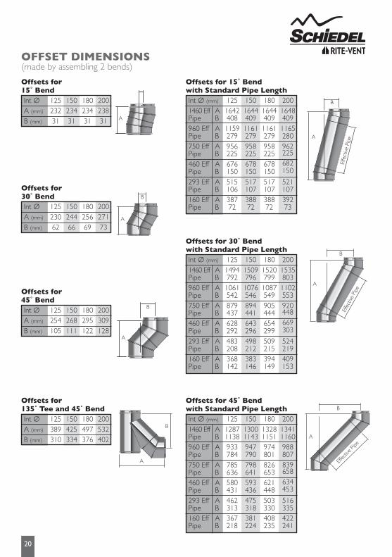
OFFSET DIMENSIONS(made by assembling 2 bends)
A
Int ØA (mm)
B (mm)
12523231
15023431
18023431
20023831
Offsets for 15˚Bend
Int ØA (mm)
B (mm)
12523062
15024466
18025669
20027173
Offsets for 30˚Bend
Int ØA (mm)
B (mm)
125254105
150268111
180295122
200309128
Offsets for 45˚Bend
Int ØA (mm)
B (mm)
125389310
150425334
180497376
200532402
Offsets for 135˚Teeand45˚Bend
A
B
A
B
B
A
B
Effe
ctive
Pip
eA
B
A
Effe
ctive
Pip
e
B
A
Effec
tive P
ipe
Offsetsfor15˚Bendwith Standard Pipe LengthInt Ø (mm)
TestingandCommissioningpriortofirstuseThis is carried out using a flue flow test as described in BS EN 15287 Parts 1 & 2, with reference to the appropriate appliance type.
Appliance OperationIf the appliance is slumbered overnight or for longer periods then it is advisable to run the appliance at controlled high fire condition for a period of at least 30 minutes. Prolonged slumbering of the appliance is a contributing factor to a system chimney failure. It is important to maintain sufficiently high flue gas temperatures in order to avoid condensate and acid corrosion problems, and to ensure complete combustion of the fuel.
Multi-Fuel ApplicationsMulti-Fuel refers to an appliance which may be used to burn either seasoned wood, or approved solid fuels. These fuels should not be mixed, as this increases the risk of deposits being built up in the liner.
MaintenanceEach chimney must be designed to allow for easy inspection; sweeping should be carried out by competent persons. On solid fuel applications a list of HETAS registered sweeps can be found at www.hetas.co.uk. Chimney flue cleaning and inspection require the use of appropriate tooling – under no circumstances should chemical cleaners or mild steel tools be used to sweep stainless steel chimneys. Cleaning/inspection of any chimney system should be carried out at least once a year, along with maintenance of the appliance, but it is recommended that chimneys serving solid fuel appliances be swept at least twice a year, at the end of the heating season to remove any deposits, which may have built up during the season, and prior to the start of the next heating season to ensure that the the flue way is clear of any blockages such as birds nests etc.We would advise that monthly checks are carried out to ensure that there is no build up of any deposits in the flue way of the connecting flue pipe or system chimney.
Fuel Storage and UsageWhere solid fuels are being used, correct storage is critical and fuels must be kept dry. Wood must be seasoned prior to use, with a maximum moisture content of 20%. Only approved fuels should be used. Refer to HETAS list for details on www.hetas.co.uk.The fuel used must be suitable for the appliance - please refer to manufacturer’s instructions.
NOTICE PLATENotice Plate for Eco ICID ProductThe Notice plate should be marked up in indelible ink and securely fixed in an unobtrusive but obvious position within the building such as:
• Next to the electricity consumer unit.• Next to the chimney installation described.• Next to the water supply stop-cock.
See example alongside:
System ChimneyT450-N1-W-V2-L50050-G60 150mm
14/02/14
24
PRODUCT WARRANTY
Under normal operating conditions and providing the system is installed correctly, it should last the lifetime of the appliance, which normally is 10 years. Eco ICID carries a 10 year conditional warranty. The conditions are that the system is:-• Correctly sized and installed in accordance with the manufacturer’s instructions, current Building Regulations and relevant British and European standards.• Maintained correctly by a qualified and competent person and maintenance records kept updated for both appliance and system chimney.• Used in combination with an appliance burning only approved fuels in accordance with Schiedel Chimney Systems and the appliance manufacturer’s instructions.• The product registration form must have been filled in by an appropriately qualified installer (see p.3 for details), and returned to Schiedel Chimney Systems Ltd.
For recommended fuels listings, please refer to the HETAS Guide www.hetas.co.ukIn the event of a fault developing in the product due to defective materials or faulty manufacture Schiedel Chimney Systems undertake to replace the product only.Schiedel Chimney Systems cannot accept liability nor take any responsibility for the installation, building or redecorating costs or any other consequential losses arising.If any complaint is found to be a result of faulty installation, non-compliance with or abuse contrary to these conditions, the cost of site investigation is chargeable.
Product RegistrationThe installer/customer is required to register the chimney installation details with Schiedel Chimney Systems Ltd. This can be done on site using Schiedel’s Installation App, or online via the warranty registration page (see bottom of page for both options) or by filling in the form below and returning it by post to the address below. Failure to register the installation may affect any claim made during the warranty period of the product.