The latest version of this report can be downloaded for free at http://Arqen.com/acoustics/ University of Victoria Faculty of Engineering Fall 2011-Spring 2012 Work Term Report ECO-RECORDING STUDIO DESIGN: II. Sustainable Acoustic Materials Arqen Sonic A division of WestRiver Industrial Inc. Prepared by Tim Perry, EIT Acoustic Designer at Arqen Sonic Electrical Engineering & School of Music Alumni [email protected]April 6, 2012 In partial fulfillment of the requirements of the B.Eng. Degree Supervisor (Professional Engineer) Name: Charlie Perry, P.Eng. Position: Principal Engineer The report is to be considered: NOT CONFIDENTIAL CONFIDENTIAL
Transcript
The latest version of this report can be downloaded for free at http://Arqen.com/acoustics/
University of Victoria
Faculty of Engineering
Fall 2011-Spring 2012 Work Term Report
ECO-RECORDING STUDIO DESIGN: II.
Sustainable Acoustic Materials
Arqen Sonic
A division of WestRiver Industrial Inc.
Prepared by Tim Perry, EIT
Acoustic Designer at Arqen Sonic Electrical Engineering & School of Music Alumni
#3-1002 Bay Street Victoria, B.C. V8T 1R9 Jonathan Foweraker Faculty of Engineering University of Victoria P.O. Box 1700 Victoria, B.C. V8W 2Y2 April 19, 2012 Dear Dr. Foweraker The attached workterm report, titled “Eco-Recording Studio Design: II. Sustainable Acoustic Materials” is the second report in a series on acoustics in sustainable architecture. It builds on the seminal report, “Eco-Recording Studio Design: I. Proposed Architectural Acoustics and Photovoltaic System”. Having spent the last five years learning about digital signal processing, audio production and acoustics, I have developed a fascination for the fields of acoustics and architectural design. This project convolves those passions with another personal interest: sustainable development. Green studio design is a personal hobby and is not the work I do on work terms—but the report is relevant to this entrepreneurial work term. My start-up, Arqen Sonic, is focussed on the sustainable design of products for recording studios. In May 2012 Arqen will test the market response to our first product, the Phantom DAW: a quiet, efficient, high performance audio workstation (a computer designed for music production). Also starting May, Arqen will offer free designs for the do-it-yourself acoustics community. The first free offering will be blueprints for simple-to-make acoustic diffusers, which I designed using numerical optimization (this was the topic of my Elec 498 Honours Thesis [1]). These diffusers are featured in the current report, because unlike most diffusers they are designed to be manufactured locally. The report focussed on sustainable materials for acoustic treatment. To qualify, a material had to be recycled, natural, abundant or renewable. Part I of the eco-studio design project revealed conflicts between acoustical design and eco-building design. The current paper focusses on solutions, and the findings suggest that acoustic control can be implemented almost entirely with sustainable materials. I would like to thank Gina Brown, Artur Galiullin, Peter Driessen, Kirk McNally, Ryan Boc, my parents, and many others who have provided support, feedback and inspiration. Sincerely, Tim Perry
i
CONTENTS
LIST OF TABLES AND FIGURES ............................................................................ II
SUMMARY ........................................................................................................ IV
GLOSSARY ........................................................................................................ V
APPENDIX A LIVE-END, DEAD-END VS. NON-ENVIRONMENT ROOMS ..................... 43
APPENDIX B EXTREME ABSORPTION IN NON-ENVIRONMENT ROOMS ..................... 45
APPENDIX C FLATTENING THE ROOM RESPONSE ................................................ 47
APPENDIX D STC60 OR HIGHER WALL CONSTRUCTIONS ...................................... 48
LIST OF TABLES AND FIGURES
TABLES Table 1 Absorption coefficients used for Control Room Simulation ...................................... 12 Table 2 Green Acoustic Insulation Products [8,9] .................................................................. 15 Table 3 Green Sound Barrier & Wallboard Products [9,10,11] ............................................ 16 Table 4 Natural Fibres (Green replacements for mineral wool) ............................................ 18 Table 5 Green Acoustic Absorption Products .......................................................................... 20
FIGURES Figure 1 Impulse response of a room, showing the ITDG, early reflections and RT60. ......... 4 Figure 2 Floor section dimensions of the conceptual control room. ......................................... 7 Figure 3 Control room side profile: splayed inner shell and live-end dead-end design. ......... 8 Figure 4 A diffused reflection’s perspective, on a trajectory toward the mixing position. ..... 9 Figure 5 X-ray perspective through the live end of the control room (sectioned view), ......... 9 Figure 6 Suggested Reverberation Times for Control Rooms. ............................................... 10 Figure 7 EVRR simulation layout with 3 studio monitors (30°angle between pairs) ........... 12 Figure 8 Absorption coefficients versus frequency for simulated surface materials. ........... 13 Figure 9 RT60 versus frequency for EVRR with estimated absorption coefficients. ............ 13
iii
Figure 10 Typical double wall construction [4]. ...................................................................... 14 Figure 11 Triple insolation shell build within an existing structure. ................................... 17 Figure 12 Absorption coefficient spectra for green absorption products. .............................. 19 Figure 13 Panel absorber wall structure for low frequency control. ..................................... 23 Figure 14 Basic membrane absorber bass trap structure. ..................................................... 24 Figure 15 Typical materials used in an acoustic control wall. (After Newell [17]) ............... 26 Figure 16 Basic floating floor assembly on decoupling rails. ................................................. 27 Figure 17 Various floating floor options for a recording studio. (After Newell [17]) ............ 28 Figure 18 The “stick room” achieves exceptional diffusion, but invites eye injury. ............. 30 Figure 19 Large tower low-frequency diffuser based on the primitive root sequence. ......... 31 Figure 20 The QRD Diffractal® by RPG Diffusor Systems. ................................................... 32 Figure 21 Low profile optimized ‘stepped’ diffusers designed for local construction using.. 34 Figure 18 Assembly of the Binary Amplitude Diffsorber, a planar hybrid surface. ............. 35 Figure 22 Plan view of a “Live-End, Dead-End” (LEDE) control room. ................................ 43 Figure 23 Plan view of a “Non-Environment” control room. .................................................. 43 Figure 24 Ideal ‘Live-End, Dead-End’ control room response. ............................................... 44 Figure 25 Elevation (top) and plan view (bottom) of a ‘Non-Environment’ room. ................ 45 Figure 26 ‘Non-Environment’ acoustic treatment at Area Master studios. .......................... 46 Figure 27 ‘Non-Environment’ control room at Tio Pete studios, Bilbao, Spain. ................... 46 Figure 28 Reflection control when free-standing loudspeakers must be used. ..................... 47 Figure 29 Composite acoustic control wall for adjusting the frequency balance of a room. . 47 Figure 30 Extreme isolation in a Toyashima room (Not a Live-End, Dead-End room). ...... 51
iv
SUMMARY
Sustainable buildings struggle with acoustic control. This fact has been driving a study in green recording studio design. The current work presents materials for acoustic treatment in the studio’s control room. To qualify, a material had to be recycled, natural, abundant or renewable. Preference was given to materials that can be locally sourced in the Vancouver region. The findings suggest that high quality acoustic treatments can be implemented almost entirely with sustainable materials. Wool, hemp, stone wool and recycled fabric products provide excellent sound insulation. Two examples are Roxul Safe’n’Sound™ and Bounded Logic UltraTouch™. Green materials for building framed isolation walls include salvaged timber, bamboo lumber and Homasote 440 SoundBarrier®. Isolation walls may also be built using rammed earth, hempcrete or sand-filled concrete blocks. Green sound absorption products are available, made from natural or recycled materials. An acoustic control wall with a built-in broadband absorption system can be constructed using mostly sustainable materials. Wood-like acoustic floors and reflective surfaces can be built from salvaged wood or rapidly renewable resources like cork tile and bamboo lumber. These materials can also be used to constructed acoustic diffusers on-site. Most diffusers are geometrically complex and hard to build; therefore, modular ‘stepped’ diffusers have been numerically optimized to facilitate simple construction using wood working tools. For surfaces that require a hybrid absorptive-diffusive treatment, the hybrid surfaces patented by RPG® are high performance, LEED certified, low profile and elegant.
Acoustician A physicist who specializes in the science of sound.
Control Room An acoustic space designed for the critical assessment of sound that is
played over speakers.
Diffuser, Acoustic A device used to treat unwanted echoes and reflections. Unlike absorption, diffusers preserve the liveliness of a room because they do not absorb much sound energy. Instead, they disperse it, spreading the energy around the room.
Diffusion (Acoustics) The re-radiation (or scattering) of an incident sound wave over a wide area. Ideal diffusion refers to a uniform spread of energy in an environment.
Early Reflections The first reflections that we hear within about 100 ms of hearing the direct sound of the source. These give important cues about our location in a room relative to the walls, floor and ceiling.
Impulse Response (IR) The impulse response of the room is its response to a delta function. Important acoustical properties like frequency response and reverberation are largely characterized by the impulse response. One can essentially listen to the impulse response of a room by standing inside it and clapping.
Initial Time Delay Gap (ITDG)
The time gap between the arrival of the direct sound that we hear, and the first early reflection. This gives an impression of intimacy in relation to walls in a room, helping a listener sense their relative position within that room.
‘Live Room’ A room with lush reverberation, used for musical performance or tracking musicians. A live room in a recording studio is typically located next to the control room. These rooms should be acoustically isolated from each other.
‘Live-End, Dead-End’ control room (LEDE)
A control room intended to allow critical listening without creating an acoustically dead environment. The front of the control room, or ‘dead-end’, relies on high absorption to prevent early reflections from interfering with the direct source during the ITDG. The back end of the control room, or ‘live-end’, is covered with broadband diffusers to scatter reflections back toward the listening position with a dense, non-uniform texture.
vi
Late Reverberation The reverberant sound field after about 100 ms, until it fully decays.
Late reverb is characterized by a dense texture of diffused reflections that reach our ears from many different paths. These diffused reflections are out of phase with one another, causing us to hear the comb filtering effect. We perceive this as ambience.
‘Non-Environment’ control room.
A room designed with a live front wall and a dead rear end (the sidewalls and ceiling are also absorptive, and the floor is reflective). Non-Environment rooms offer a better critical listening environment than a ‘Live-End, Dead-End’ room, at the expense of liveliness. Some people find these rooms sound uncomfortably sterile when performing tasks other than critical listening. (After Newell [2]).
Resonant Room Modes (or Eigenmodes)
Resonances in a room, largely determined by its geometry. Because a control room is relatively small, widely spaced resonant modes will occupy the lower region of the audible spectrum. A listener positioned in a high pressure region for particular modal frequency will hear an exaggerated volume at that frequency (a ‘modal peak’), and a de-emphasized volume when positioned in a low pressure region.
Reverberation (Reverb) The indirect sound that reaches a listener from a source. If this indirect sound is well-diffused, reverberation is said to have a rich texture and is perceived as a pleasant ambience.
RT60 (Reverberation Time)
The time it takes for the acoustic signal to decay by 60 dB. The reverb time varies throughout the frequency spectrum.
Studio Monitors Accurate speakers with a neutral response, designed for critical listening.
Texture, Reverb Texture is a measure of acoustical quality that is characterized by the number and distribution of reflections that arrive at the listener during the first 100 ms, after the perception of the direct source.
1
1. INTRODUCTION
Founded by the author in late 2011, Arqen Sonic exists to push the envelope of responsible design in the audio industry. Arqen provides environmentally conscious solutions for recording studios, and user friendly technical resources for the acoustics and audio production communities. In May 2012 Arqen will test the market response to our first product, the Phantom DAW: a quiet, efficient, high performance audio workstation (a computer designed for music production). A central goal of the Phantom DAW project is to promote less wasteful practices in product design1. Also starting May, Arqen will offer free designs for the do-it-yourself acoustics community. The first free offering will be blueprints for simple-to-make acoustic diffusers2, which were designed by the author using numerical optimization [1]. This paper is a follow-up to a previous report: Eco-Recording Studio Design I: Proposed Architectural Acoustics and Photovoltaic System [3]. In Part I, acoustical design was used to determine optimal parameters for a recording studio control room and live room, identify architectural dimensions to achieve those parameters, and derive electrical appliance loads from the architectural dimensions. Recording studios have high power demands and may be operated for extended hours, consuming large amounts of energy. The purpose of photovoltaic system sizing was to estimate the portion of that energy need that may be satisfied by building-integrated photovoltaics. This follow-up paper, Part II, focusses on sourcing and evaluating sustainable materials to use as high performance acoustic treatment. A specific acoustic treatment scenario will be addressed, called the ‘live-end-dead-end’ control room design.
1 Most consumer electronics have an unnecessarily short life due to planned obsolesce or intrinsic obsolesce—in other words, people are driven to frequently replace their electronics. Much waste can be eliminated by designing high quality products with modular components that can be upgraded (rather than replacing the entire device). 2 An optimized sound diffuser is an acoustic treatment device that is expensive to buy and difficult to design (because the computational design system requires physical modeling). Instead of buying diffusers, many end users try to build their own by mimicking commercial designs [1].
2
1.1. Green Goals Present Challenges to Acoustical Design Sustainable buildings struggle with noise control. Studies by the Center for the Built Environment and the National Institute of Building Science found that green buildings outperform ‘brown’ buildings in nearly all measures of occupant satisfaction—except acoustical comfort. [4] Potential solutions to this issue are being explored through the conceptual design of an environmentally sustainable recording studio. The construction and operation of recording studios place special challenges on sustainable development: Architectural acoustics may conflict with common green-building practices such as
natural lighting, natural ventilation, and radiant heating and cooling. Windows for natural lighting may produce undesirable reflections for certain applications, while radiant heating and natural ventilation conflict with acoustic isolation (sound-proofing).
Studios are constructed using specialized materials and procedures. Commonly used
green building materials have resulted in structures with offensive acoustics; fortunately, eco-friendly acoustic products do exist and continue to emerge. [5]
Studios use equipment that draws a lot of power, often day and night.
Studios are used day and night by a small group of people who work long hours and
may temporarily live on-site.
1.2. Objective and Scope The objective of this paper is to find environmentally friendly materials that can be used to provide high performance acoustic treatment. A specific acoustic treatment scenario will be addressed, called the ‘live-end-dead-end’ control room design. A control room was conceptually designed in Part I [3], which will serve as a reference acoustic space when needed. 1 Part I also includes acoustical specifications for a musical performance room (‘live room’), an estimation of facility size, electrical load requirements and photovoltaic system sizing. Most of these topics are not revisited in the current paper, but many of the materials suggested will be applicable to the live room, and acoustic rooms in general.
3
Materials will be suggested based on measures of acoustic performance, the ability to source locally, and green building design standards such as the Leadership in Energy and Environmental Design (LEED®) rating system. Suitable materials are those that are recycled, natural, abundant or renewable. Suitable acoustical products must be recyclable or biodegradable and should be reusable where possible. Materials and products must not pose hazards to health and should be highly fire resistant where feasible.
2. ACOUSTICS PRIMER
Clap your hands in a large room. The clapping sound is a rapid burst of broadband noise, meaning it has energy at all frequencies. It resembles a mathematical entity called a delta function, or unit impulse. The resulting reflections and ambience that you hear after exciting the room, is reverb. Reverberation is the indirect sound that reaches a listener from a source. From any source there is sound that reaches the listener in a direct path, as well as sound that reaches the listener indirectly through reflections in the acoustic space. This reflected sound travels further than the direct sounds before reaching the listener, thus it is delayed. It has also been diffused by certain surfaces, and lost energy due to propagation through the air and absorption in the room. The reflected/diffused sound continues to interact with its surroundings, until it has been fully absorbed.
The impulse response (IR) of the room is its response to a delta function. Important acoustical properties like frequency response and reverberation are largely characterized by the impulse response. One can essentially listen to the impulse response of a room by standing inside it and clapping.
2.1. Early Reflections and Late Reverb Reverb can be understood by viewing the impulse response of a room. Reverb has two main components:
4
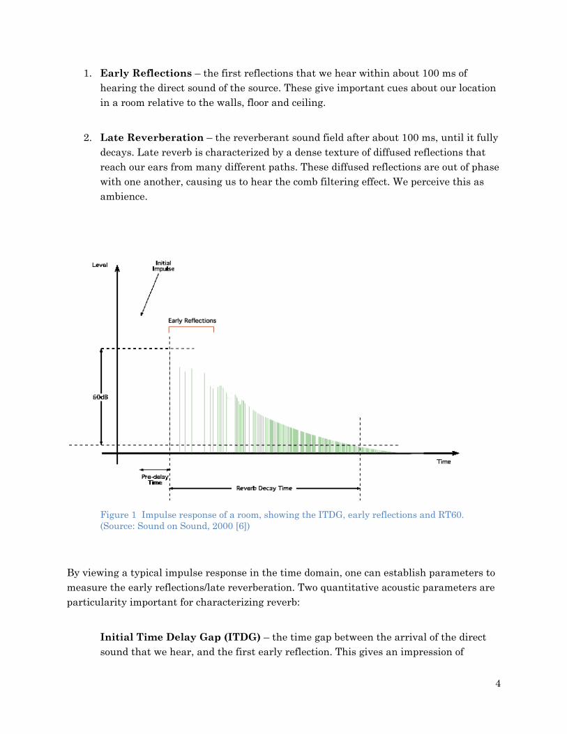
1. Early Reflections – the first reflections that we hear within about 100 ms of hearing the direct sound of the source. These give important cues about our location in a room relative to the walls, floor and ceiling.
2. Late Reverberation – the reverberant sound field after about 100 ms, until it fully decays. Late reverb is characterized by a dense texture of diffused reflections that reach our ears from many different paths. These diffused reflections are out of phase with one another, causing us to hear the comb filtering effect. We perceive this as ambience.
Figure 1 Impulse response of a room, showing the ITDG, early reflections and RT60. (Source: Sound on Sound, 2000 [6])
By viewing a typical impulse response in the time domain, one can establish parameters to measure the early reflections/late reverberation. Two quantitative acoustic parameters are particularity important for characterizing reverb:
Initial Time Delay Gap (ITDG) – the time gap between the arrival of the direct sound that we hear, and the first early reflection. This gives an impression of
5
intimacy in relation to walls in a room, helping a listener sense their relative position within that room.
RT60 - the reverberation time, RT60, is the time it takes for the acoustic signal to decay by 60 dB. The reverb time varies throughout the spectrum, and can be measured at discrete frequency values. For practical applications, averaging schemes are used to define the reverb time in the portion of the spectrum where human hearing is most sensitive (between about 125 Hz and 4000 Hz is where we perceive the most significant sound colouration by reverb). RT60 is a function of the volume of a room and the absorption of sound energy inside that room, defined according to the Sabine and Eyring equations.
2.2. Control Room Acoustics The recording studio control room is a listening space designed for the critical assessment of acoustic signals. There are strict requirements as well as subjective considerations for control room acoustics. Even with modern simulation tools in the hands of acousticians and acoustical engineers, the acoustics of complex control rooms can be difficult to predict. In Part I a conceptual design of a recording studio control room was outlined. The room was designed for stereo reproduction of a signal through speakers. The impression of sound is subjective; however, there are a number of key characteristics that define a control room with quality acoustics. The following ideal control room characteristics were used as design guidelines:
Ideal Control Room Characteristics The acoustic balance of a source signal is clearly perceived and phantom images
(sound sources perceived through speakers) are heard at the correct location in the stereo field.
The listening position receives no significant acoustic distortions such as those caused by early reflection comb filtering, flutter echo and modal ringing.
The ideal control room will exhibit a flat frequency response in the listening position, such that the frequency balance of an acoustic signal is reproduced perfectly. In other words, the control room should not add a noticeable impression to the sound through colouration. In small rooms modal resonances must be addressed because they obscure the frequency balance of acoustic signals.
6
The acoustics of the original recorded space should be clearly perceived during playback: The first reflection heard by the listener should be a reproduced reflection that occurred in the recorded space. It should not be a reflection produced by the listening room. Since most recorded spaces are larger than control rooms, realizing this is goal requires special design considerations to suppress early reflections.
The control room should exhibit a well-defined initial time delay gap, such that the impression of a larger room may be perceived. When listening to an acoustic signal through speakers, a listener should hear the early reflections and exponential decay that is embedded in that signal.
A controlled, diffuse reverb texture should be present, and RT60 should be optimized for the volume of the room such that it sounds natural. To maintain the source frequency balance, RT60 should be similar throughout the audible spectrum. Reverb should allow for controlled liveliness without compromising the clarity of the direct sound source.
The control room interior should be acoustically isolated from all sources of undesirable noise.
3. ACOUSTICAL SPECIFICATIONS
This section documents key elements of the conceptual control room design from Part I [3], and summarizes the acoustical specifications. This information will be used to help evaluate green acoustic materials.
3.1. Control Room Conceptual Design Overview Several room dimension ratios were investigated to minimize resonant mode problems in rectangular rooms. Ultimately, the rectangular shape lost in favour to a splayed wall control room. The floor section (Figure 2) shape was borrowed from the Auralex “Acoustics 101 Room” [7] and scaled by a factor of 1.35 to facilitate a high splayed ceiling. The purpose of splayed walls is to prevent flutter echo, prevent uniform buildup of resonant modes, and create a reflection free zone about the listener when proper acoustic treatment is applied.
7
Figure 2 Floor section dimensions of the conceptual control room. Dimensions are based on the "Acoustics 101 Room", but scaled up by a factor of 1.35.
A ‘live-end, dead-end’ concept was applied, with the goal of creating a well-defined initial time delay gap. The front of the control room, or ‘dead-end’, relies on high absorption to prevent early reflections from interfering with the direct source during the ITDG. The back end of the control room, or ‘live-end’, is covered with broadband diffusers to scatter reflections back toward the listening position with a dense, non-uniform texture. These diffused reflections will be spread out in space and time, creating a pleasant ambience, and will reach the listener after a well-defined ITDG. This lets the listener perceive the first reflection of an acoustic signal that was recorded in a larger space, because it can be heard before the control room’s first reflection. Therefore the spatial impression the the larger room can be perceived in the control room.
8
Figure 3 Control room side profile: splayed inner shell and ‘Live-End, Dead-End’ design. Double wall construction is used on the outer shell to provide acoustic isolation. The front end of the room is surfaced with heavy broadband absorption (not explicitly shown) to create a reflection free zone around the listener. The back end shows samples of low frequency absorbtion (corner bass traps and a Helholtz resonator or membrane absorbers) and broadband RPG Skyline® diffusers. In practice, the room will require extensive low frequency absorption with a much greater coverage than depicted by the illustrated bass traps. The ceiling and sidewalls are treated with a combination of insulation and reflection phase-grating diffusers. In practice, the Auralex T-Fusers® (displayed beside the mixing position) should be moved back to create a larger ITDG, or better yet, be replaced by diffusers that only scatter reflections toward the back wall.
Figure 4 A diffused reflection’s perspective, on a trajectory toward the mixing position.
Figure 5 X-ray perspective through the live end of the control room (sectioned view), looking forward through the reverberant sound field. Full acoustic treatment is not shown.
10
Simulations were performed on a rectangular room with the approximate equivalent average volume to the control room. This was called the equivalent volume rectangular room (EVRR). The dimensions of the EVRR were estimated: Effective Length = 27’= 8.229 m Average Effective Width = 23’ – 7 1/16” = 7.187 m Average Outer Shell Height = 14’ – 7” = 4.45 m
The simulation results in Part I provided useful feedback that can be used to modify the room characteristics. It was difficult to map many of the parameters to the splayed wall control room; therefore, many decisions for the conceptual design were based on research and intuition, with the design criteria in mind.
3.2. Reverberation time and absorption coefficients
Figure 6 Suggested Reverberation Times for Control Rooms. Source: Architectural Acoustics, 2006 [8].
Optimal reverb time for a control room is somewhat subjective, and depends on the size of the room. The goal is to allow a natural spatial impression that does not colour the sound. Too little reverb and the control room will sound unnaturally dead; too much reverb and we compromise the clarity of the direct sound—and with it our ability to critically assess recordings. Additionally, RT60 will be slightly different at each frequency. Several sources recommend an RT60 average between 0.3 and 0.5 seconds in the 500 Hz and 1 kHz frequency bands. Others recommend a reverberation time between 0.2 and 0.4 seconds as an average in the one-third-octave bands from 200 Hz to 4 kHz. A tighter guideline prefers reverberation times in the 0.3 to 0.4 second range for average control room volumes [8].The Audio Engineering Society recommends the following formula to calculate Tm, the nominal reflected sound reverberation time between 200 Hz and 4 kHz [8]:
11
Tm ≈ 0.25 (V/V0)1/3 (3.1)
Where V is the volume of the listening room, and V0 is the reference room volume (V0 = 100 m3). A target Tm is estimated using the equivalent volume rectangular room:
V = 263.18 m3
Tm ≈ 0.345 s
3.2.1. Simulated absorption coefficients and resulting RT60
To simulate the soundfield in the equivalent volume rectangular room, absorption coefficients for the wall materials first needed to be assigned. RT60 is a function of the room volume and the average absorption of each surface, as described by the Sabine (left) and Eyring (right) equations [9]:
(3.2) where V is the volume of the room, Stot is the total surface area, and αsab and αey are coefficients that represent the average absorption of all surfaces. The EVRR was simulated using a MATLAB script for RoomSim. The script takes into consideration many test and environmental parameters; some parameters are well defined, several have been estimated. The volume of the EVRR is 263.18 m3, based on the average dimensions of the control room as specified in Section 4.1. In attempt to estimate the acoustics of the partially treated EVRR, the absorption coefficients in Table 1 (plotted in Figure 8) were used in the simulation. The goal was to simulate untreated sidewalls, while simulating acoustic treatment on surfaces that can be reasonably defined. The reasonably defined surfaces are the back wall (the “live end”, a diffusive surface) and the front wall (the “dead end”, a surface with high absorption in most places, but also containing a window).
12
Figure 7 EVRR simulation layout with 3 studio monitors (30°angle between pairs) at a 2.2m radial distance, angled 10 degrees down toward the listening position for sources. Two simulated omnidirectional test microphones separated by 14.5 cm are located in the listening position as sensors (listening position used is at 38% of the length dimension back from the front wall, centered widthwise at a height of 1.2m).
Table 1 Absorption coefficients used for Control Room Simulation
Surface Main Surface Material Simulated
125 Hz 250 Hz 500 Hz 1 kHz 2 kHz 4 kHz
Back Wall (Ax1)
RPG Skyline diffusor (attenuation at 125 Hz added)
0.15 0.34 0.28 0.29 0.19 0.16
Front Wall (Ax2)
hypothetical 50% broadband attenuation (acoustic foam and glass)
0.75 0.75 0.75 0.75 0.75 0.75
Side Wall 1 (Ay1)
gypsum wallboard 0.3 0.1 0.05 0.04 0.07 0.1
Side Wall 2 (Ay2)
gypsum wallboard 0.3 0.1 0.05 0.04 0.07 0.1
Floor (Az1)
varnished cork parquet on joists (floating)
0.15 0.11 0.10 0.07 .0.06 0.7
Ceiling (Az2)
acoustic tile (suspended) 0.5 0.7 0.6 0.7 0.7 0.5
The RT60 simulation was run using a generalized version of the Eyring equation at six frequency bands, taking into account environmental parameters such as room temperature, humidity and air density (typical values were used). The results are displayed in Figure 9.
13
Figure 8 Absorption coefficients versus frequency for simulated surface materials.
Figure 9 RT60 versus frequency for EVRR with estimated absorption coefficients.
The estimated RT60 results for the partially treated control room are encouraging. The values are certainly between 0.3 and 0.5 seconds throughout the hearing spectrum. However, additional absorption is needed to get closer to the goal Tm≈0.345 s. This absorption will also have a secondary purpose: to adjust the frequency balance of the room. These findings suggest that it is not ideal to simply place acoustic treatment products on the walls. A thick layer of broadband absorption will be needed over much of the interior surface. A more elegant solution for tuning the frequency balance of the control room is to integrate an acoustic control system into the splayed walls.
0 500 1000 1500 2000 2500 3000 3500 40000
0.1
0.2
0.3
0.4
0.5
0.6
0.7
0.8
0.9
1
Frequency (Hz)
Abs
orpt
ion
Coe
ffici
ent
Absorption Coefficients vs Frequency
Ay1Ax1Ay2Ax2Az1Az2
103
0
0.2
0.4
0.6
0.8
1
Frequency Hz
RT6
0 se
c
Reverberation Time vs Frequency
14
4. ACOUSTIC INSULATION AND NOISE REDUCTION
A critical listening room should be acoustically isolated from its surroundings to prevent sound transmission. Isolation depends largely on structural design which is not the focus of this paper. There are many options for wall construction including precast concrete, hempcrete and rammed earth walls; however, timber frame construction and a standard isolation technique called “room within a room” will be assumed here. This assumption will be used to explore sound insulation and barrier materials for studios in general, rather than a specific studio design.
4.1. Attenuation through walls Attenuation caused by transmission loss through walls depends on a number of factors, but mainly the thickness and density of the material used. Standard wall construction permits excessive transmission, as sound has a resonant pathway from one side of the wall to the other along the wall studs. Staggered stud construction can reduce this problem by decoupling the inner and outer wall surfaces from each other. For even better sound attenuation, a change of medium such as an insulated air gap is helpful, followed by another dense obstacle. Additionally, vibration dampening structures can be added to walls to reduce the transmission at problem frequencies. The “room within a room” concept employs double walls, spaced apart and treated with material that adds mass and provides extra attenuation. In the conceptual design, 2x4 studs were used, with a spacing of 6” between the inner and outer walls. Together, these two walls will be referred to as the isolation wall. Proper double wall construction can yield high STC ratings in the range of STC 70, which is the goal for acoustic isolation in certain demanding critical listening environments. As a general rule, the control room should achieve STC > 45 for any given barrier (including windows and doors).
Figure 10 Typical double wall construction [4].
15
4.2. Green materials for insulation and soundproofing Environmentally friendly products for soundproofing are readily available. Two high potential insulation products are given in Table 2. Bounded Logic UltraTouch™ is incredibly versatile: it is suitable as thermal insulation for exterior walls, acoustic insulation and broadband sound absorption. The merits of UltraTouch™ will be discussed further in Section 5, where it is viewed as a potential broadband absorber. Roxul Safe’n’Sound™ is designed as a sound insulator for interior walls, therefore Roxul does not publish R-Values for the product (but they do suggest that it provides high R-Values). From a standpoint of sustainability and convenience, Safe’n’Sound™ offers higher utility than UltraTouch™ when used as an interior wall insulator:
• Safe’n’Sound™ is a standard building material available in many hardware stores. At the time of this writing UltraTouch™ is only distributed by one BC supplier.
• Safe’n’Sound™ is manufactured in BC. UltraTouch™ is manufactured in Arizona.
Both products achieve LEED points and are made from high recycled content using energy efficient processes. Roxul products, for example, can help builders earn up to 32 points toward LEED certification. Given the number of variables it is not straightforward to judge which product is the greener solution However, Safe’n’Sound™ is a logical choice because it is regionally produced and available close to most job sites.
Table 2 Green Acoustic Insulation Products [9,10] Product Name Thickness R-Value Absorption/Transmission Coefficients
@ Octave Band Frequencies (Hz) Fire Rating
125 250 500 1000 2000 4000 NRC/STC
Bonded Logic UltraTouch™ Recycled denim. Factory in Arizona. BC distributer. [9]
3.5” (5.5“ and 8”
also available)
R-13 0.95 21
1.3 40
1.19 48
1.08 52
1.02 46
1.0 48
1.15 NRC 45 STC
(interior wall with wood
studs)
UL-723
Roxul Safe’n’Sound™ Stone wool made from basalt and slag. Factory in BC. [10]
Table 3 Green Sound Barrier & Wallboard Products [11,12,13]
Product Name Product Type Sound Transmission Class (STC) and Impact Isolation Class (IIC) Notes
Fire Rating
Homasote 440 SoundBarrier® FSC-certified. 98% post-consumer recycled paper. No asbestos or formaldehyde. Water recycling at factory. [11]
Sound barrier for walls, floors and ceilings. Potential replacement for lightweight gypsum [11].
Basic interior wall with metal studs, 3.5” batt insulation: STC 51 [11] *Single Steel Stud Wall on 24” center walls: STC 60 [11] Wood Floating Floor: STC 52 and IIC 51 [11]
UL, 1 hour
(wall assembly)
Flame spread Class C
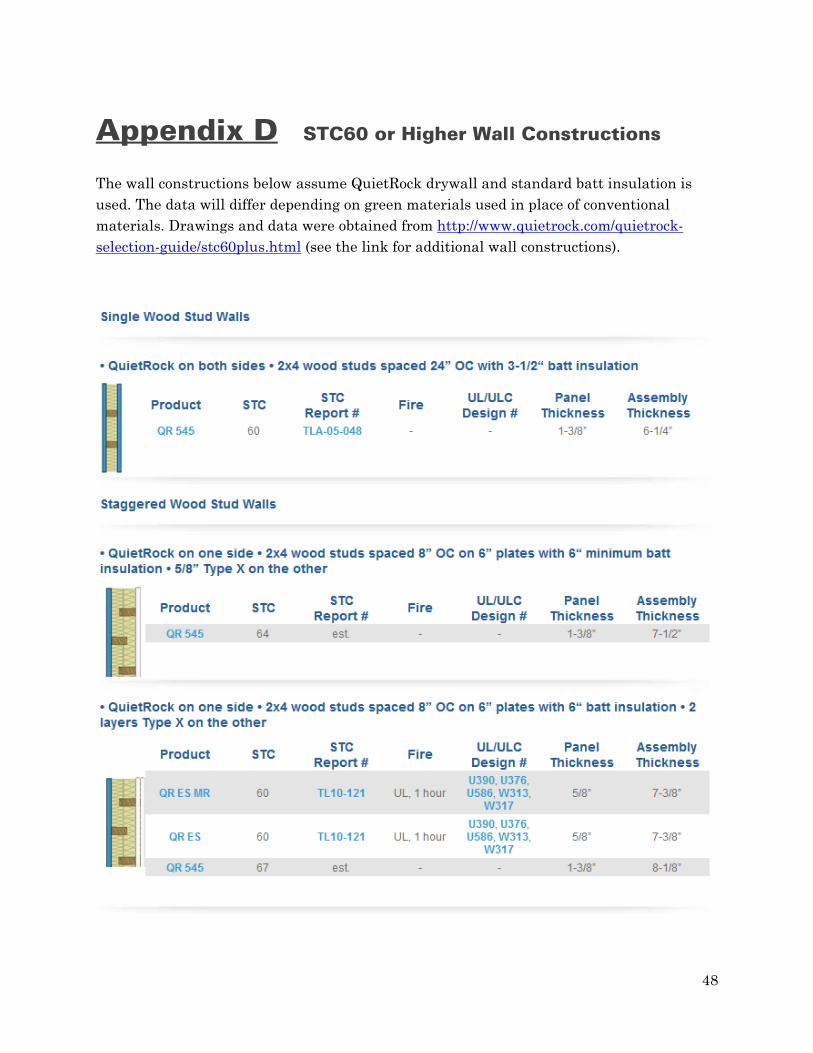
QuietRock™ drywall 4% recycled. Can reduce waste by minimizing gypsum requirements. May be used to earn points under 2 of the 6 LEED-NC categories. Maximum 6 LEED points can be earned. [12]
Drywall replacement.
Basic interior wall with metal studs, 3.5” batt insulation: STC 51 [12] Up to STC 80 for double wall construction with batt insulation (see Appendix D) [12]
Peacemaker 3.2 mm: STC 19 – 1 layer stapled to 4’x8’ frame of 2”x2” pine [13] Peacemaker 6.4 mm: IIC 55 – single layer [13]
FF 1-70 Pill
Table 3 gives examples of sound barrier and wallboard products that are marketed as environmentally friendly. The product of greatest interest is Homasote 440 SoundBarrier®. Made from 98% post-consumer recycled paper, it is an established sound barrier for walls, floors and ceilings [11]. Homasote 440 has potential as a replacement for lightweight gypsum wallboard, and may be useful for the low frequency control interior walls discussed in Section 6.3. Beyond timber frame or steel frame walls, there are other solutions for sound isolation structures that may not require commercial insulation products. One approach to soundproofing using locally sourced materials is to build the isolation wall using hollow concrete blocks filled with dry sand. Figure 11 illustrates this, showing an apartment that was converted to a studio.
17
Figure 11 Triple insolation shell build within an existing structure. Hollow concrete blocks filled with dry sand provide locally sourced, economical soundproofing. (After Newell [12])
18
5. BROADBAND ABSORPTION
Large amounts of broadband absorption will be installed on the front (“dead end”) of the control room. To achieve a reflection free zone about the listening position, the front end should absorb early reflections and return as little as possible to the listener. The splayed wall design should alleviate slap and flutter echo problems; however, the front portion of the sidewalls may require broadband absorption to make the reflection free zone possible.
To effectively bring RT60 down across the spectrum, with the goal Tm= 0.345 s, absorption at all frequencies could be installed in patches onto the bare walls. These patches would be applied symmetrically on both sidewalls. The amount of coverage will determine the broadband reduction of RT60. However, there must not be so much absorption coverage as to prevent the splayed walls from doing their job: transferring early reflections to the back (“live-end”) of the control room. This also holds true for the ceiling, which will be largely surfaced with absorption, complemented by diffusers. Patch work is fine for medium to high frequency absorption, but for low frequency absorption a more elegant solution is to implement the acoustic control wall shown in Section 6.3.
5.1. Sustainable materials for broadband absorption Commercial studios employ extensive absorption systems, often using mineral wool (fiberglass) or cotton waist as a bulk absorptive material [2]. A possible replacement for mineral wool is sheep wool, which has a much lower environmental impact. It is useful where high absorption coefficients are not required, such as for filling cavity walls. Sheep wool has a low density and flow resistivity, therefore it needs to be thick (5-10 cm) to achieve high absorption [14].
Table 4 Natural Fibres (Green replacements for mineral wool)
Product Name Thickness Range
Material Notes Fire Rating
Steico Canaflex™ Hemp (Poland) [15]
40-240 mm Hemp fibres, Ammonium phosphate, polyolefin fibres.
EN 13501-1 E
EdenBloc35™ Sheep wool (UK) [16]
50-100 mm (custom up to
350 mm)
Recycles wool (>60% w/w) with a natural bio-polymer. Contains an albumen stabiliser (<10% w/w/) and a mineral fire retardant (<4%).
Varies depending on face material.
19
ThermaFleece™ EcoRoll Sheep wool (UK) [17]
50-140 mm 75% wool, 15% recycled polyester lofting agent, 10% polyester with 20% recycled content. ACOUSTIC PROPERTIES EN ISO 11654:1997 - 100mm - Aa 1.00, Class A EN ISO 11654:1997 - 50mm - Aa 0.75, Class B
BS 5803-4
While fibrous materials often have superior absorption, recycled granular materials may offer better sustainability [14]. Reapor™ is a non-combustible inorganic foam that achieves high absorption and low environmental impact over its life cycle. Reapor™ is made from recycled material and is recyclable at the end of its life. It is fibre-free, moisture resistant, non-combustible, and suitable for both outdoor and indoor use [14].
5.2. Green broadband absorption products
Table 5 and Figure 12 present a range of commercial absorbers that are marketed to be greener than traditional foams. Many of these products are marketed to consumers who are not building studios—they are treating existing rooms. For these customers 2” absorbers make sense for control of medium to high frequencies, and separate products are available for low frequency control (“bass trapping”) or broadband absorption (such products are typically bass traps covered with fibrous or porous absorption). For example, the RPG Modex Broadband provides effective absorption from 50-5000 Hz while being only 4” thick.
Figure 12 Absorption coefficient spectra for green absorption products.
20
Table 5 Green Acoustic Absorption Products Product Name Thickness Absorption Coefficients @ Octave Band Frequencies (Hz) Fire
Rating 125 250 500 1000 2000 4000 NRC
Bounded Logic Acoustic Panels 8’x4’x2” Recycled cotton. BC Factory. [18]
2” (custom acoustic solutions available)
0.35 0.94 1.32 1.22 1.06 1.03 1.15 Class A
Bonded Logic UltraTouch™ Recycled denim. Arizona Factory. BC distributer.
Micro (wood panel with fine perforation) [21] FSC certified wood (Swiss)
2” (3” and 8”
also available)
0.18 0.75 1.13 1.03 0.88 0.74 0.95 Class A
21
In general the thicker and denser the product, the better it is at absorbing lower frequencies. In a new studio it makes sense to build the absorption system right into the wall, and thick absorption is necessary for a ‘live-end, dead-end’ room. Thicker means more material, so it had better be a sustainable material. An objective comparison of the “greenness” between materials was not practical in this work, nor was it necessary. Instead, products can be eliminated using the following criteria:
1. For a new studio construction, only products offered in variable thickness will be considered.
2. For a studio constructed in BC, only products sourced in North America will be considered.
3. Only products with published LEED data will be considered.
The remaining absorption candidates come from very different companies: • RPG® products, coming from a company that specializes in innovative acoustical solutions.
• Bounded Logic products, coming from a company that specializes in natural fibre insulation.
Bounded Logic UltraTouch™ and custom products are particularly attractive for creating the “dead-end” of the room. UltraTouch™ is
• Relatively cheap.
• A good absorber across in all octaves of interest3.
• Dense, providing better low frequency damping and thermal insulation than mineral fibre.
• Made from denim and cotton fibers that are 100% recyclable.
• 80% post-consumer recycled content (by weight).
• Manufactured using a minimal amount of energy.
• Energy Star and LEED approved.
• Available in 3.5”, 5.5” and 8” thicknesses.
• Warehoused in Abbotsford BC (essentially Vancouver).
An obvious downside to UltraTouch™ is that because it is designed as in-wall insulation it is not aesthetically pleasing to look at. The interior wall can be finished with a thin layer of another material that 3 The absorption coefficient spectra for the 3.5” Bounded Logic UltraTouch™ has a peak at the 250 Hz octave frequency, which is not a bad thing. While it would seem preferable to have a constant absorption coefficient across all bands, the goal in this case is simply to absorb all the energy that hits the front wall. Extra low frequency absorption is useful because low frequencies are more difficult to absorb than high frequencies. Also, high frequency energy naturally rolls off more quickly during propagation through air.
22
provides high frequency absorption, such as recycled cotton. Where appropriate it can be surfaced with a professional product like RPG BAD® panels4 (this is a hybrid surface, discussed in Section 9). An RPG BAD system or perhaps Topakustik® Type 5/3 wood panels would work well on the splayed ceiling. The ceiling requires a mix of absorption and diffusion such that early reflections are transferred to the back of the room while a reflection free zone is maintained around the listener.
6. LOW FREQUENCY ABSORPTION
Bass traps are necessary to dissipate modal energy in the control room, even if a splayed outer shell is used. The modal response characteristics and the frequency response plots5 from Part I [3] indicate that special attention must be given to treating room modes. For this conceptual design, specific solutions cannot be practically specified for the splayed wall control room. However, the control room will share at least one train of modal resonances with the tested equivalent volume rectangular room: axial modes in the central portion of the length dimension, occurring at integer multiples of 20.9 Hz. This first targeted mode occurs at the bottom edge of our hearing, but higher order axial modes may be more perceivable (41.8 Hz, 62.7 Hz, 83.6 Hz, etc.).
6.1. Resonant absorbers Resonant absorbers include panel absorbers and Helmholtz resonators. These act on the pressure component of a sound wave6, therefore they are best placed close to the hard walls of the room where the resonant modes have a maximum pressure component [2]. Resonant absorbers work by converting acoustic energy into heat:
• Panel absorbers vibrate when excited by acoustic energy, which gets converted into heat by internal friction losses within the panel material.
• Helmholtz absorbers consist of resonant air cavities with narrow openings. During resonance, friction loss occurs due to high particle velocities through the openings.
4 RPG BAD® panels are highly absorptive up to about 2kHz, and diffusive at higher frequencies. 5 The modal and frequency response plots from Part I [3] were not included in this report because they do not give specific insight into the true response in a splayed wall room. 6 Fibrous/porous absorbers act on the velocity component of an acoustic wave, while resonant absorbers act on the pressure component.
23
A variation of the Helmholtz resonator is a perforated sheet with resonator mouths (holes) less than one half wavelength apart7. Perforated sheets act over a larger area than Helmholtz resonators due to diffraction effects [12]. The tightly spaced mouths enhance each other’s radiation resonance, such that a perforated sheet can absorb a range of frequencies around resonance. To target the fundamental axial mode for the room length, a Helmholtz resonator will be installed centrally, at the rear of the room. The Helmholtz resonator cavity can be accurately tuned to a particular resonance, and the bandwidth may be widened by adding fiberglass absorption inside the resonant chamber [1]. The natural fibre materials given in Table 4 are potential green alternatives to fibreglass. Modular Helmholtz resonator blocks are available in precast concrete, and can potentially be manufactured locally (like cinder blocks). Helmholtz resonators work over a relatively narrow frequency range, thus they don’t solve all low frequency problems.
Figure 13 Panel absorber wall structure for low frequency control. The partitioning between the rigid side wall and the absorber wall is called ‘Camden Partitioning’. The resonant frequency of a self-standing room shell made from walls like these would depend on the distance ‘D’ and wall mass. A typical resonant frequency for such a room shell is about 20 Hz. (After Newell [17])
24
6.2. Membrane absorbers Another approach to low frequency control is membrane absorbers. These vibrate in sympathy with sound waves within an effective frequency range, causing attenuation by absorbing energy at those frequencies. Membrane absorbers will also be useful in back of the control room, as they reflect higher frequencies.
Figure 14 Basic membrane absorber bass trap structure. Low frequency sound striking the plywood panel causes vibrations, which are damped by the fiberglass. [7]
In general, bass traps will be used to widen the modal bandwidth of resonant modes by decreasing the Q of modal peaks. This is an important step toward evening out the low end frequency response of the room. Additionally, a side effect of standing waves is modal ringing, where certain low frequencies have significantly longer decay times compared with others. Increasing the modal bandwidth will reduce the average reverb decay time in the low frequencies, revealing additional clarity [7]. Low frequency absorption will be installed throughout the control room in attempt to dissipate as much modal energy as possible. In rectangular rooms, corners are typically the first to be treated with bass traps. With the splayed wall design, however, specific modal problems are more difficult to predict. An overall balance of low frequency absorption and diffusion coverage in the control room can be installed underneath broadband acoustic
25
treatments, and should improve the room frequency response. The specific choices that will lead to a marked improvement in bass management will require professional evaluation and detailed simulations.
6.3. A low frequency acoustic control wall A low frequency control system can be embedded into the walls of the control room. The splayed interior geometry can be implemented as a timber frame skeleton with acoustic control walls (Figure 15). The dead sheet bonded to waste felt in Figure 15 is typically sold as a product called PKB-2®. A membrane absorber is created when this material is nailed to the studs on the interior surface of the wall [2]. The resulting structure combines a panel absorber (the dead sheet sandwiched between plasterboards) with a membrane absorber (the deadsheet composite). This is expected to provide low frequency absorption from about 30 Hz to 250 Hz, where the heavy panels provide most of the control in the lower octave [2]. The wall of Figure 15 can be mostly implemented using sustainable materials:
• Salvaged timber from sources like old buildings or beetle damaged forests. Bamboo lumber is another sustainable alternative, if it can be sourced locally.
• Bounded Logic Ultratouch® is an excellent choice for the absorption between studs. Alternatives are wool or hemp natural fiber products, provided they are sourced locally.
• Homasote 440 SoundBarrier® can be used in place of the plasterboard.
• Products made from recycled materials such Audimute’s Peacemaker™ sound barrier may serve as a replacement for a plasticised dead sheet.
26
Figure 15 Typical materials used in an acoustic control wall. (After Newell [17])
The amount spacing between the internal wall and the outer isolation wall is important for low frequency reflection control. A larger space is preferable as it will generally produce less low frequency reflection. In studio rooms, a spacing of 5-10 cm between the isolation walls and the acoustic control walls is usually suitable [2]. Appendix C gives additional examples of wall systems that can be used to flatten the room response.
27
7. REFLECTIVE, FLOATING FLOORS
A floating floor is helpful for acoustic isolation from low frequency sounds, such as drums or terrestrial rumble (for example, from nearby heavy vehicles or machines). The floor can be largely decoupled from the foundation or existing floor beams by using narrow channel supports that have difficulty transmitting low frequencies. In the conceptual design the intended floor structure is similar Figure 16, with a top surface of floating cork floor tiles. There are other practical floor constructions (Figure 17) that can accommodate a variety of surface materials.
A similar concept can be used to decouple the ceiling from the supporting structure. The inner shell ceiling may be suspended using “Z” suspension channels. These channels will allow some high frequency transmission; however, high frequencies are easier to attenuate than low frequencies.
Figure 16 Basic floating floor assembly on decoupling rails. See Appendix D for an example of a professional control room floor assembly. Sealection® 500 is marketed as an environmentally friendly spray foam insulation that conforms to LEED quality guidelines [22]. If locally sourced, natural-based materials (such as hemp products) may give superior insulation and offer the advantage of being more sustainable.
28
Figure 17 Various floating floor options for a recording studio. (After Newell [17])
7.1. A green approach to a reflective floor Floors in recording studios are generally constructed from reflective wood. Wood provides a warm visual aesthetic and a rich timbre that is familiar to musicians—particularly for those like cellists and contrabassists, who rely on floor contact to enhance the area of their soundboard. Here are four environmentally friendly alternatives to a traditional hardwood floor:
29
• Cork tiles. The bark of cork trees is rapidly renewable, and the use of such flooring conserves hardwood forests. Floating cork floors provide some natural insulation and can be constructed with minimal structural framework (in residential applications, cork is often placed over a concrete sub-floor with only a moisture barrier in between). The absorption coefficients and timbre will depend on the varnish, thickness of the cork and the structural framework under the floor. Cork has a warm visual aesthetic and contains organic patterns that appeal to most people8.
• Bamboo lumber. Bamboo regenerates rapidly and grows in Asia, India, Australia, parts of Africa and North and South America. Bamboo is extremely durable and lightweight. Its fibers are used to create light coloured plywood with a unique grain and an exotic look. Bamboo flooring is used today as a sustainable and affordable alternative to hardwood.
• Locally salvaged timber such as reclaimed lumber or pine beetle damaged wood.
• Wood products that are certified with the forest stewardship council (FSC).
8 While subjective, the wide appeal of a cork floor is supported by a universal design principle called 'Wabi-sabi' [54].
30
8. DIFFUSIVE SURFACES
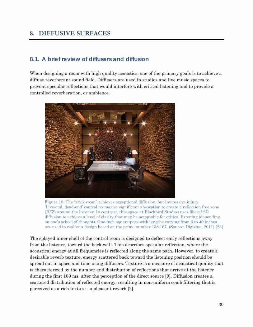
8.1. A brief review of diffusers and diffusion When designing a room with high quality acoustics, one of the primary goals is to achieve a diffuse reverberant sound field. Diffusers are used in studios and live music spaces to prevent specular reflections that would interfere with critical listening and to provide a controlled reverberation, or ambience.
Figure 18 The “stick room” achieves exceptional diffusion, but invites eye injury. ‘Live-end, dead-end’ control rooms use significant absorption to create a reflection free zone (RFZ) around the listener. In contrast, this space at Blackbird Studios uses liberal 2D diffusion to achieve a level of clarity that may be acceptable for critical listening (depending on one’s school of thought). One-inch square pegs with lengths varying from 6 to 40 inches are used to realize a design based on the prime number 138,167. (Source: Digizine, 2011) [23]
The splayed inner shell of the control room is designed to deflect early reflections away from the listener, toward the back wall. This describes specular reflection, where the acoustical energy at all frequencies is reflected along the same path. However, to create a desirable reverb texture, energy scattered back toward the listening position should be spread out in space and time using diffusers. Texture is a measure of acoustical quality that is characterized by the number and distribution of reflections that arrive at the listener during the first 100 ms, after the perception of the direct source [9]. Diffusion creates a scattered distribution of reflected energy, resulting in non-uniform comb filtering that is perceived as a rich texture - a pleasant reverb [2].
31
Diffusors will be used to create a controlled ambience in the control room. In addition, the frequency balance in the listening position will most likely be improved, as it will be represented by a more even blend of the original acoustic signal spectra. The first diffusers that interact with the sound will be reflection phase-grating diffusers, located at on the sidewalls and ceiling. The purpose of these is to scatter the first reflections while angling them toward the back wall. In the “live-end, dead-end” control room, the most important diffusion will take place on the back wall. Here diffusers must produce a dense texture of reflections that scatter back toward the listener. For the conceptual control room design in Part I, most of the back wall was covered with RPG Skyline® diffusers. These are omnidirectional diffusers that are based on primitive root number theory. Skyline® diffusors exhibit a near-uniform diffusion capability across the hearing spectrum [11]. Additional improvements to modal ringing are possible through the use of low-frequency diffusers. For example, a low-frequency primitive root-sequence diffusor at the extreme rear of control room can be used to clean up modal interference. Sound can be diffused over an extended bandwidth (from low to high frequencies) by using self-symmetric fractal diffuser like the RPG DiffractalTM [7]. Fractal formations are an elegant solution to the periodicity, absorption and bandwidth problems which limit the performance of many diffusers [14]. Fractals are generated by nesting high frequency diffusers within low frequency diffusers, providing full spectrum diffusion within a single device [24,14].
Figure 19 Large tower low-frequency diffuser based on the primitive root sequence. The smaller upper diffuser is based on the quadratic-residue sequence. Location: the recording studio of Studio Sixty, Lausanne, Switzerland [2].
Figure 20 The QRD Diffractal® by RPG Diffusor Systems. Left: Construction of the Diffractal consists of first and second generation fractals based on the quadratic residue sequence. Right: Polar scattering response for seven periods of an (a) QRD and (b) QRD Diffractal at the high design frequency. Simulated using near-field Kirchhoff diffraction theory (After Cox and D’Antonio [25]).
8.2. A green approach to sound diffusion Sound diffusers typically have a complex geometry. Like any product, companies manufacture them and ship them worldwide. However, from a sustainability perspective it is wasteful to ship large, heavy acoustic devices globally from a central location. Diffusers are expensive; so many do-it-yourself studio builders invest time to emulate commercial designs using woodworking tools. In the authors opinion the most environmentally friendly diffusers are those that can be built on site from sustainable materials. This provided motivation to design “lean-optimized” acoustic diffusers [1]. These are low profile, optimized diffusers designed for local construction using local materials and low precision manufacturing (wood working tools). The designs are also modular, manufactured from small, repeatable units. “Lean” is a manufacturing principle that calls for extreme efficiency and the elimination of waste. The objective of this “lean” diffuser optimization was to design modular diffusers that provide an optimal trade-off between uniform scattering and compact geometry, and to
33
design them without the need for boundary element predictions9. The approach involved leveraging the strengths of finite difference time domain simulation, while accommodating the weaknesses. Success relied on cyclic prototyping and the intrinsically parallel property of evolutionary algorithms. The designs are simple to implement. The optimization framework produces sequences of low natural numbers (the set of integers between zero and 16), useful for designers who need to work in low precision. The resulting designs can be constructed by carpenters or hobbyists, on-site, out of any suitable material that has a low absorption coefficient. Such materials include wood and bamboo lumber. The bottom diffuser in Figure 21, the Stepfractal is a fractal formation of an optimized ‘stepped’ diffuser. It produced very good broadband diffusion when simulated using finite difference time domain, suggesting that this diffuser or a similar design would be suitable on the back wall of the control room. A potential method of constructing the Stepfractal is to implement the first level of the fractal (which provides low-mid frequency diffusion) using woodworking tools. The second level of the fractal can also be built using woodworking tools, but would be easier to produce locally using a 3D printer.
9 An ideal acoustic diffuser is a surface that causes an incident sound wave from any direction to be evenly scattered in all directions. The design of optimized diffusers has remained the domain of experts; notably, the industry’s leading innovator, RPG Diffuser Systems [38]. It appears that diffuser optimization is avoided by designers and acoustical engineers because it requires a sophisticated framework. The heart of this framework is a simulation to predict acoustic scattering. For this a boundary element model is the natural choice, but the development of such a framework is a large task in itself. One objective of the “lean” diffuser optimization problem was to develop a simplified optimization framework, using finite difference time domain simulation instead of boundary element predictions.
34
Figure 21 Low profile optimized ‘stepped’ diffusers designed for local construction using local materials and low precision manufacturing (wood working tools). The bottom diffuser is a fractal formation that produced very good broadband diffusion when simulated using finite difference time domain. The extreme top and bottom images show acoustic waves scattering from these diffusers during simulation. Details of the design by optimization process are given in [1].
35
9. HYBRID DIFFUSIVE-ABSORPTIVE SURFACES
Hybrid surfaces achieve variable impedance by using patches of absorptive and reflective material. These diffusers can be designed with excellent dispersion characteristics, but their applications are limited as they cannot be designed for minimum absorption. In environments that require simultaneous control of absorption and diffusion (such as the ceiling of a control room), hybrid surfaces offer attractive benefits:
• Manufacturing is simple and cheap. • Hybrid surfaces have a shallow profile compared with other diffusers. • Treatment can be easily hidden to blend in with any environment. • Optimization gives complete control over the reflectivity [26].
RPG® Diffusor Systems designs the industry standard hybrid surfaces. These surfaces comply with LEED requirements. In the author’s opinion the RPG® hybrid surfaces are the greenest high performance diffuser systems on the market—thanks to their compact, simple, efficient design.
9.1.1. Planar hybrid surfaces
The Binary Amplitude Diffsorber (or BAD™ panel) by RPG® is a flat hybrid surface constructed from a porous absorber faced with a perforated mask (Figure 22). Such panels are often highly absorptive up to about 2 kHz, thus only the diffusion performance over mid-to-high frequencies needs to be considered [27,14].
Figure 22 Assembly of the Binary Amplitude Diffsorber, a planar hybrid surface. Porous absorber (left), reflective mask (middle), and optional fabric covering (right). (After Cox and D’Antonio [14])
Specular reflections are attenuated, but not eliminated when using flat hybrid surfaces. Curvature can be incorporated into the design to break up specular reflections, resulting in a surface with similar absorption to the BAD panel, but greatly improved dispersion. Curved hybrid surfaces are particularly useful in the control room as they enable the sweet spot to be spatially expanded [14]. In applications where moderate absorption is acceptable, they may compete with other diffuser designs: for example, a curved hybrid surface can be designed with one quarter the depth of a rigid optimized curved surface, and achieve diffusion of almost the same quality [14].
1. CONCLUSIONS
The acoustic treatment in a recording studio control room can be implemented almost entirely with sustainable materials. Mineral wool (fiberglass) can be replaced by products made from natural fibres such as wool or hemp. Other alternatives are recycled cotton or denim. Two excellent candidates for insulation between wall studs are Roxul Safe’n’Sound™ and Bounded Logic UltraTouch™. Both are environmentally friendly and have excellent acoustic properties. Safe’n’Sound™ offers perhaps the highest utility for interior wall insulation because it is regionally produced and available close to most job sites. There is no shortage of green materials for creating isolation walls. Lightweight gypsum can be replaced with Homasote 440 SoundBarrier®, a superior acoustic insulation product made from 98% post-consumer recycled paper. With assistance from a structural engineer, isolation walls may be built from local materials such as rammed earth, hempcrete or concrete blocks filled with sand. Bounded Logic insulation products offer great versatility for acoustic treatment. UltraTouch™ is useful not only for soundproofing, but also as an absorber in acoustic control walls. Broadband absorption can be built into an acoustic control wall, built using green products such UltraTouch™ in place of mineral wool, Homasote 440 SoundBarrier® in place of plasterboard, and salvaged or bamboo lumber. To control specific room modes, Helmholtz resonator concrete blocks can be locally cast and incorporated into a wall.
37
The need for reflective wood-like surfaces can be satisfied using salvaged wood, bamboo lumber and cork tiles. Unlike hardwood forests, bamboo and cork are rapidly renewable. Sustainable solutions to quality sound diffusion are not straightforward. The back wall of the control room requires a large diffuser system, as do acoustic spaces in general. While RPG® makes high quality environmentally friendly diffusers, they are not locally available. To avoid the need to ship large diffusers, the author has designed space efficient, modular, optimized sound diffusers. These are designed to be built using local labour and materials such as salvaged wood or bamboo lumber. For surfaces that require a hybrid absorptive-diffusive treatment, The Binary Amplitude Diffsorber (or BAD™ panel) by RPG® provides precise acoustic control. Good design is sustainable design. Compact, simple and LEED certified, the elegance and efficiency of its design makes the BAD™ panel an intrinsically sustainable product. Because good design is sustainable design.
2. EXTENSIONS AND RECOMMENDATIONS
The structural elements of studio design need further investigation. RPG® makes a series of isolation and masonry products that may provide efficient ways to incorporate acoustic control into the structure. For example, the RPG Diffusor Blox® is a concrete CMU that can be incorporated into a cinder block wall to provide either absorption or diffusion. Ideally such precast concrete devices would be locally cast.
Sustainable acoustic treatment for live rooms needs to be addressed. While materials will be similar, the acoustic goals are different.
Certain diffusers, such as optimized curves, were not discussed in this paper. There may be sustainable practices that can be applied when manufacturing large, curved diffusers.
Together, Part I and Part II of this study in eco-recording studio design have covered the following:
• Conceptual architectural acoustics for the control room and live room.
• Estimated facility size and electrical load requirements.
There is much to cover before a feasibility study can be completed. Most of the following design work would be done by a team of architects and engineers.
Detailed design of solar power systems Site selection and evaluation is essential to formally assess the photovoltaic potential of the facility. Sustainable development requires that the design conforms to the site—not vice-versa. Shading Analysis of the site is necessary to determine the true insolation and photovoltaic potential, accounting for shadows cast on the site by nearby obstacles such as buildings and trees. Formal photovoltaic system design must be conducted, including the investigation of 2-axis sun tracking arrays to satisfy the unmet power demand. Solar power system modeling will involve the transient simulation of the specified system to test its expected year round operation. Simulations are a simple, low-cost way to assess a system before building it.
Detailed acoustical design and physical modeling Assistance from an acoustical consulting engineer is recommended to make optimal control room design decisions. Also, noise and vibration assessment/control must be considered when forming a complete model of the room’s acoustics. Methods of computationally modeling acoustical systems include ray-tracing, beam tracing, boundary element predictions and finite element vibro-acoustic simulations.. A future objective is to analyze the control room and live room using finite element analysis to simulate the geometry (as a finite element mesh), and model the eigenmodes and nonlinearities in the room. Ray-tracing, beam tracing or boundary element predictions can be used to assess the behaviour of the early reflections, with the goal of designing a reflection-free-zone at the front of the control room.
39
Eco-building design Designing a sustainable recording studio will require a competent architectural firm and feedback from engineers, acousticians and environmental designers. Acoustical design will constrain eco-building designers, and eco-building design will constrain acoustical designers. Many elements of sustainable architecture must be considered, including natural acoustic insulation provided by green roofs, rainwater collection, modular prefabricated construction. Significant design decisions will have to consider the items listed below. Heating, cooling and ventilation: Solar thermal panels (i.e., solar hot water or “wet” solar panels). Solar radiation with thermal mass10 heating and cooling. Natural convection driven ventilation using underground cooling tubes, windows
Choosing local materials and construction methods: Round earth walls. Insulating concrete form. Pine beetle damaged wood. Recycled materials. Design for safety in seismic events.
Feasibility study and economics analysis
Feasibility questions are expected to emerge periodically during the design of an ecologically friendly recording studio. Economic considerations are currently under investigation. Items to consider include Upfront costs and funding. Return on investments. Cost-benefit-analysis. Global economic trends.
10 Thermal mass heating: the sun heats a mass—e.g., it shines through a south-facing window onto dense surfaces such as rammed-earth walls, a brick floor, etc. When the temperature of the room drops below the temperature of the walls, heat is released from the walls into the space.
40
REFERENCES
[1] T. Perry, "The Lean Optimization of Acoustic Diffusers: Design by Artificial Evolution, Time Domain Simulation and Fractals," University of Victoria, Victoria, Honours Thesis 2011.
[2] P.R. Newell, Recording Studio Design, 3rd ed. Boston, USA: Focal Press, 2012. [3] T. Perry, "Eco-Recording Studio Design: I. Proposed Architectural Acoustics and
Photovoltaic System.," Arqen Sonic, Victoria, 2012. [4] National Institute of Building Science. (2010, August) Whole Building Design Guide:
Acoustic Comfort. [Online]. http://www.wbdg.org/resources/acoustic.php [5] M. Noble, D. Kennedy. (2008, July) "Acoustic Design Performance in Green Buildings",
Sustainable Architecture & Building Magazine (SABMag). [Online]. http://www.sabmagazine.com/blog/2008/07/21/acoustic-design/
[6] Sound on Sound. (2000, May) Reverb FAQ. [Online]. http://www.soundonsound.com/sos/may00/articles/reverb.htm
http://www.bondedlogic.com/construction-products/acoustical-panels [19] RPG Diffusor Systems Inc. (2012, April) RPG Diffusor Systems website. [Online].
http://www.demilec.com/english/sealection-500-architects [23] Digizine. (2011, Oct.) George Massenburg builds a blackbird room. Image. [Online].
http://www2.digidesign.com/digizine/dz_main.cfm?edition_id=101&navid=907 [24] T.J. Cox and P. D'Antonio, "Fractal Sound Diffusers," in Proc. Audio Eng. Soc. 103rd
Conv., New York, 1997, p. 4578. [25] P. D'Antonio and J. Konnert, "The QRD Diffractal: A New One- or Two-Dimensional
Fractal Sound Diffusor*," J. Audio Eng. Soc., vol. 40, no. 3, pp. 117-129, March 1992. [26] T.J. Cox and P. D'Antonio, "Optimized Planar and Curved Diffsorbors," in Proc. Audio
Eng. Soc. 107th Conv., New York, 1999, p. 5062. [27] J.A.S. Angus and P. D'Antonio, "Two Dimensional Binary Amplitude Diffusers," in
Proc. Audio Eng. Soc. 107th Conv., New York, 1999, p. 5061. [28] Sustainable Architecture & Building Magazine (SABMag). (2011, April) 2008-2010
SABAwards Winning Projects. [Online]. http://www.sabmagazine.com [29] M. Monks, B.M. Oh, and J. Dorsey, "Audioptimization: Goal-Based Acoustic Design,"
IEEE Comput. Graph. Appl., vol. 20, no. 3, pp. 76-91, June 2000. [30] RPG Diffusor Systems, Inc. (2000) CHAOS: The Collaborative Holistic Acoustical
Optimization System. [Online]. http://www.rpginc.com/products/chaos/index.htm [31] T.J. Cox, "The optimization of profiled diffusers," J. Acoust. Soc. Am., vol. 97, no. 5, pp.
2928-36, 1995. [32] AES-4id-2001, "AES Information document for room acoustics and sound
reinforcement systems - characterisation and measurement of surface scattering uniformity," J. Audio Eng. Soc., vol. 49, no. 3, pp. 149-65, 2001.
[33] W. Lidwell, K. Holden, and J. Butler, Universal Principles of Design, 2nd ed., K. Elam, Ed. Beverly, USA: Rockport Publishers, 2010.
[34] J. Kreskovskt, Single woofer Room Response Simulator (Excel Spreadsheet), 2008. [35] D. Campbell, RoomSim acoustic toolbox for MatLab, 06 June 2007. [36] L.L. Doelle, Environmental Acoustics. New York, NY: McGraw-Hill, 1972.
Appendix A Live-End, Dead-End vs. Non-Environment Rooms
Figure 23 Plan view of a “Live-End, Dead-End” (LEDE) control room. A reflection-free zone is created around the listener in a LEDE room. (After Newell [2])
Figure 24 Plan view of a “Non-Environment” control room. These rooms are designed with a live front wall and a dead rear end (the sidewalls and ceiling are also absorptive, and the floor is reflective). Non-Environment rooms offer a better critical listening environment than a LEDE room, at the expense of liveliness. Some people find these rooms sound uncomfortably sterile when performing tasks other than critical listening. (After Newell [2]).
44
Figure 25 Ideal ‘Live-End, Dead-End’ control room response. a) Maximizing the initial time delay gap. b) Minimal reflection suppression required to create reflection-free zone. (After Newell [2])
45
Appendix B Extreme Absorption in Non-Environment Rooms
Figure 26 Elevation (top) and plan view (bottom) of a ‘Non-Environment’ room.
(After Newell [2], Courtesy of Tom Hidley)
46
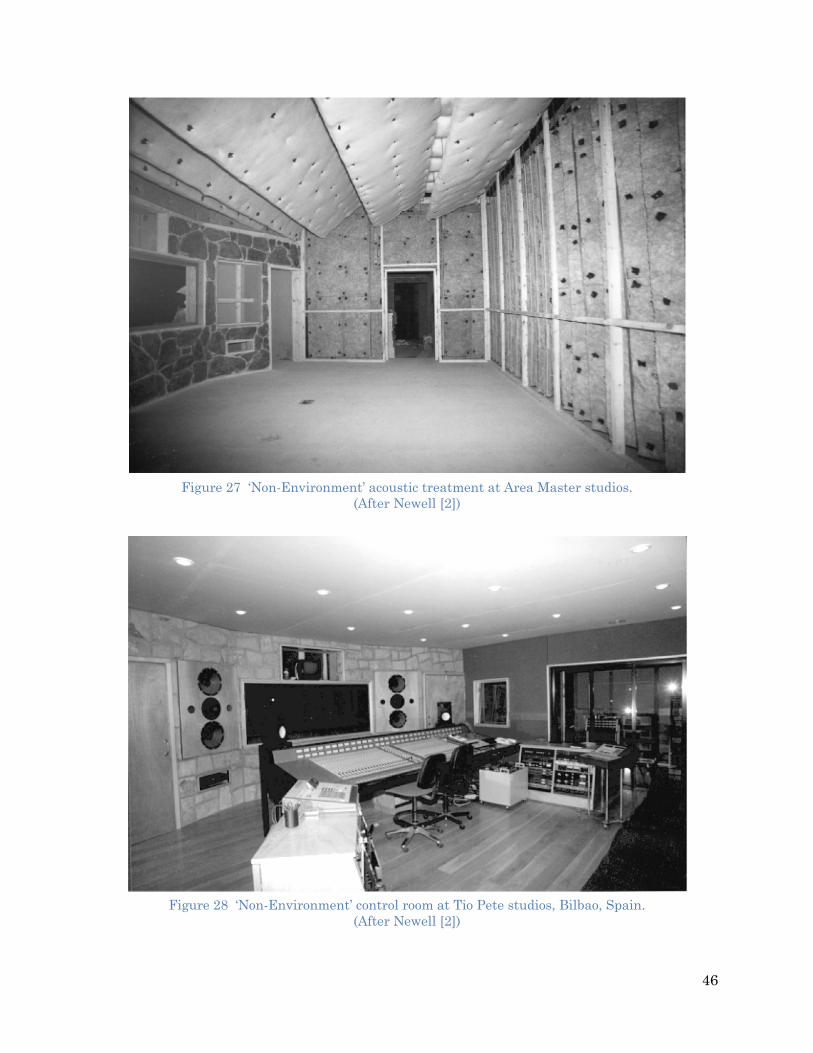
Figure 27 ‘Non-Environment’ acoustic treatment at Area Master studios.
(After Newell [2])
Figure 28 ‘Non-Environment’ control room at Tio Pete studios, Bilbao, Spain.
(After Newell [2])
47
Appendix C Flattening the room response
Figure 29 Reflection control when free-standing loudspeakers must be used. This solution was designed for BBC by Bob Walker. (After Newell [2])
Figure 30 Composite acoustic control wall for adjusting the frequency balance of a room. The wall combines membrane absorber, panel absorber and amplitude reflection grating. The frequency balance can be controlled down to low frequencies, and the liveliness can be controlled by varying the ratio or hard to soft surfaces. (After Newell [2])
48
Appendix D STC60 or Higher Wall Constructions The wall constructions below assume QuietRock drywall and standard batt insulation is used. The data will differ depending on green materials used in place of conventional materials. Drawings and data were obtained from http://www.quietrock.com/quietrock-selection-guide/stc60plus.html (see the link for additional wall constructions).
Figure 31 Extreme isolation in a Toyashima room (Not a Live-End, Dead-End room). a) Elevation view of wall, floor and ceiling construction. b) Alternate ceiling construction.