TABLE OF CONTENTS SECTION 1: INSTALLATION Subject Page A. Receiving & Inspection………………………………………………………………….. 2 B. Dimensions……………………………………………………………………………….. 2 C. Burner Component Identification..……………………………………………….…….. 3 D. Combustion Flighting……………………………………………………………………. 3 E. Mounting Burner…………………………………………………………………………. 3 F. Fuel Manifold Installation………………………………………………………………... 4 G Natural Gas Fuel Piping System……………………………………………………….. 5 H. Light Oil Fuel Piping System……………………………………………………………. 9 I. Heavy Oil Fuel Piping System………………………………………………………….. 12 J. Liquid Petroleum (LP) Gas Fuel Piping System……………………………………… 14 K. Burner Pilot Connection………………………………………………………………… 18 L. Primary Air……………………………………………………………………………… 19 WARNING These instructions are intended for use only by experienced, qualified combustion start- up personnel. Adjustment of this equipment by unqualified personnel can result in fire, explosion, severe personal injury or even death To make changes to the burner or adjust firing inputs: 1. Shut the burner down; 2. Make changes; 3. Restart the burner. STAND CLEAR OF THE BURNER UNDER ANY FIRING CONDITIONS ES-9 INSTRUCTIONS ECO-STAR TM BURNER ES-25 – ES-50 These instructions are intended to serve as guidelines covering the installation, operation, and maintenance of Hauck equipment. While every attempt has been made to ensure completeness, unforeseen or unspecified applications, details, and variations may preclude covering every possible contingency. WARNING: TO PREVENT THE POSSIBILITY OF SERIOUS BODILY INJURY, DO NOT USE OR OPERATE ANY EQUIPMENT OR COMPONENT WITH ANY PARTS REMOVED OR ANY PARTS NOT APPROVED BY THE MANUFACTURER. Should further information be required or desired or should particular problems arise which are not covered sufficiently for the purchaser's purpose, contact Hauck Mfg. Co. HAUCK MANUFACTURING CO., P.O. Box 90 Lebanon, PA 17042-0090 717-272-3051 2/12 www.hauckburner.com Fax: 717-273-9882
Transcript
TABLE OF CONTENTS SECTION 1: INSTALLATION Subject Page A. Receiving & Inspection………………………………………………………………….. 2 B. Dimensions……………………………………………………………………………….. 2 C. Burner Component Identification..……………………………………………….…….. 3 D. Combustion Flighting……………………………………………………………………. 3 E. Mounting Burner…………………………………………………………………………. 3 F. Fuel Manifold Installation………………………………………………………………... 4 G Natural Gas Fuel Piping System……………………………………………………….. 5 H. Light Oil Fuel Piping System……………………………………………………………. 9 I. Heavy Oil Fuel Piping System………………………………………………………….. 12 J. Liquid Petroleum (LP) Gas Fuel Piping System……………………………………… 14 K. Burner Pilot Connection………………………………………………………………… 18 L. Primary Air……………………………………………………………………………… 19
WARNING
These instructions are intended for use only by experienced, qualified combustion start-up personnel. Adjustment of this equipment by unqualified personnel can result in fire, explosion, severe personal injury or even death To make changes to the burner or adjust firing inputs: 1. Shut the burner down; 2. Make changes; 3. Restart the burner. STAND CLEAR OF THE BURNER UNDER ANY FIRING CONDITIONS
ES-9
INSTRUCTIONS
ECO-STARTM BURNER ES-25 – ES-50
These instructions are intended to serve as guidelines covering the installation, operation, and maintenance of Hauck equipment. While every attempt has been made to ensure completeness, unforeseen or unspecified applications, details, and variations may preclude covering every possible contingency. WARNING: TO PREVENT THE POSSIBILITY OF SERIOUS BODILY INJURY, DO NOT USE OR OPERATE ANY EQUIPMENT OR COMPONENT WITH ANY PARTS REMOVED OR ANY PARTS NOT APPROVED BY THE MANUFACTURER. Should further information be required or desired or should particular problems arise which are not covered sufficiently for the purchaser's purpose, contact Hauck Mfg. Co.
SECTION 2: OPERATION Subject Page M. General Information………………………………………………………………. 20 N. Burner Capacities…………………………………………………………………... 20 O. Fuel Oil Atomizer……………………………………………………………………. 21 P. LP Nozzle……………………………………………………………………………. 22 Q. Burner Pilot System………………………………………………………………. 22 R. Operation……………………………………………………………………………. 23 S. Adjustments…………………………………………………………………………. 23 T. Maintenance…………………………………………………………………………. 24 U. Recommended Spare Parts……………………………………………………….. 26 Appendix: Dimensional Drawings, ES 25-50 Y6931…………………… 27 Dimensional Drawing, Rack Mounted Fuel Manifold Y5493... 28 Q754 – Eco-StarTM Gas Orifice Plate Flow Chart…………….. 29 Recommended Flight Design – Weld-In Y7100……………… 30 Component Identification ES 25-50 Y6932…………………… 38 Required Reference: Appropriate Burner Data Sheet Appropriate Fan Curve GJ73 Dryer Drum Gas Analysis GJ75 Eco-Star Application Sheet
SECTION 1: INSTALLATION A. RECEIVING AND INSPECTION Upon receipt, check each item on the bill of lading and/or invoice to determine that all equipment has been received. A careful examination of all parts should be made to ascertain if there has been any damage in shipment.
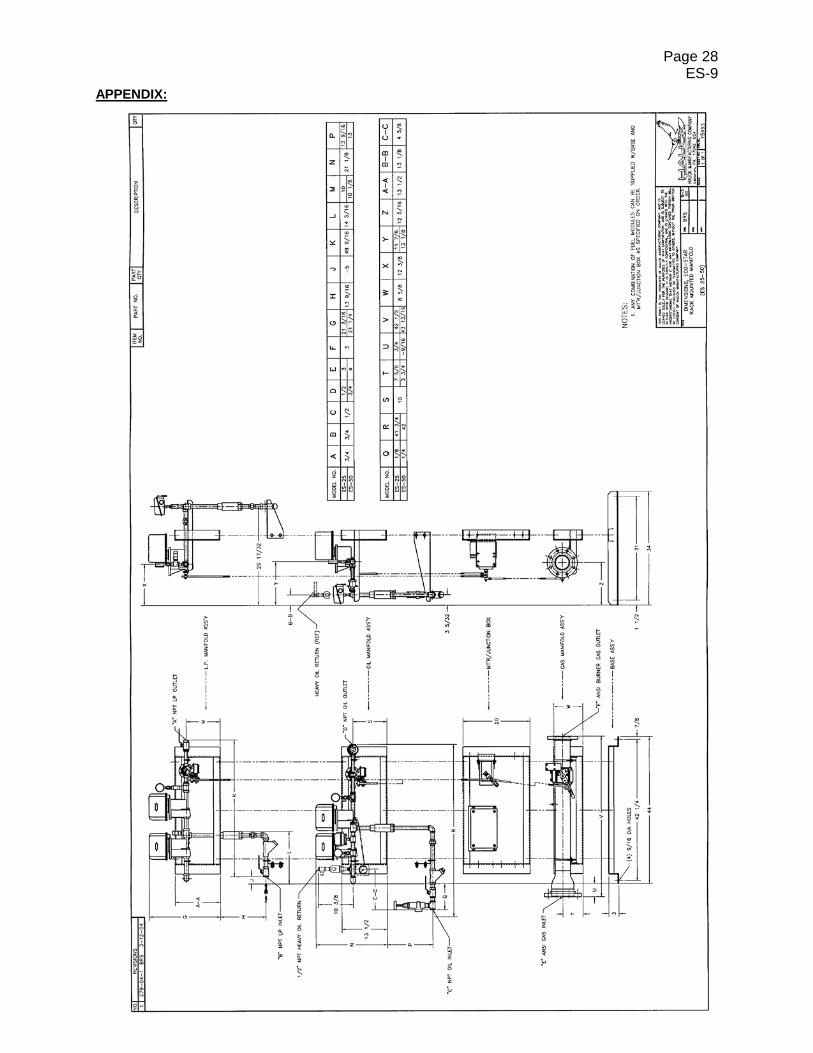
B. DIMENSIONS Eco-Star™ burner and fuel rack dimension drawings are located in the appendix. CY6931 – Dimensions, ES-25 through ES-50 CY5493 – Dimensions, Rack Mounted Fuel Manifold ES-25 through ES-50
WARNING This equipment is potentially dangerous with the possibility of serious personal injury and property damage. Hauck Manufacturing Company recommends the use of flame supervisory equipment and fuel safety shutoff valves. Furthermore, Hauck urges rigid adherence to National Fire Protection Association (NFPA) standards and insurance underwriter’s requirements. Operation and regular preventative maintenance of this equipment should be performed only by properly trained and qualified personnel. Annual review and upgrading of safety equipment is recommended.
IMPORTANT If the installation is delayed and the equipment is stored outside, provide adequate protection as dictated by climate and period of exposure. Special care should be given to all motors and bearings, if applicable, to protect them from rain or excessive moisture.
WARNING
Adjustment of this equipment and its components, by unqualified personnel, can result in fire, explosion, severe personal injury, or even death.
Page 3 ES-9
C. COMPONENT IDENTIFICATION For Eco-Star™ burner component identification, see drawings CY6932 for ES-25 through ES-50 located in the appendix. D. COMBUSTION FLIGHTING Flight design in the combustion zone is very important. Correct flighting can minimize pollutant emissions, and provide heat shielding to keep the drum surface temperature down. To obtain complete combustion, the combustion zone must be sized to provide enough combustion volume for the flame to burn, and it should also be clear of vailing material that can quench the flame, resulting in poor combustion efficiency. Combustion flights provide protection for the drum by shielding it from direct flame radiation. Construction of the combustion flights should be such that no material is allowed to fall through the flame. Combustion flights should also have a means of dissipating heat to prevent their destruction by the flame. This is typically done by plowing material over the fights and keeping the flights as low as possible to the drum. Consult Hauck for details on flight design and combustion zone requirements. See drawings Y7100 in appendix, for dimensions and installation recommendations. See Hauck Application Sheet GJ75 for additional data on applying an Eco-StarTM on a rotary dryer. E. MOUNTING BURNER 1. The burner should be mounted on the drum centerline at the same pitch as the drum.
Install a structure to support the burner. Refer to dimensional drawings in the appendix. The support structure must be able to support the weight of the burner (see table 1). If the fuel rack and primary Turbo Blower are to be mounted on the same structure as the burner, allow for the additional weight. Consult Hauck for recommended burner mounting options. Choose a suitable location for the fuel rack and primary TBA blower. The pipe rack should be firmly attached to the base structure or concrete pad. The rack is supplied with mounting holes in the base angle iron. See appropriate dimensional drawing in the appendix for dimensions. Consult TBA blower instruction sheet for proper mounting instructions for the primary blower.
2. The burner is supplied with lifting eyes to facilitate lifting the burner into place. Do not
use the lifting eye on the main blower motor for lifting the entire burner unit. The Fiberglass Turbo Blower is also supplied with lifting eyes on the blower frame. Do not use the motor lifting eye to lift the entire fiberglass blower unit.
Eco-Star™ Approximate Burner Weights
Model No. 25 50 Pounds* 1850 2750
Table 1 (*does not include TBA blower, valve trains or piping)
3. The burner can be ordered with a split-mounting flange that can be bolted onto the dryer
breech plate. This allows positioning the burner at various insertion depths past the breech plate. Typical burner insertion depth is 18" to 24”. Cut out a hole in the breech plate 2 inches in diameter larger than the burner tube. Do not weld the split-mounting flange to the burner body, as the breech will expand and contract with changes in temperature. If the split-mounting flange is welded to the burner, heat and stress will damage the burner. Tightly seal the burner to the breech. If using oil as a primary fuel, the insertion depth may have to extend more than 24” due to the amount of radiant heat in an oil flame depending on the application.
Page 4 ES-9
Model No. 25 50 Part No. 56546x 56547x
Table 2 Eco-Star™ Burner Split mounting flange
(Mounting plate OD can be specified with order) 4. To provide visual flame observation, Hauck recommends installing an observation port,
part #53849, in the drum bulkhead. (Available separately) 5. Bolt the burner to the support structure. 6. Wire the main fan motor and the turbo blower motor per instructions on the motor. 7. Rotation of all blowers must be checked prior to burner startup. The rotation is marked
with an arrow on the blower housings. Do not operate the burner until all blowers are checked for rotation and are correctly rotating. As a rule of thumb, the main blower rotates counterclockwise viewing from the motor side. The fiberglass blower rotates toward the outlet connection.
F. FUEL MANIFOLD INSTALLATION. The Eco-StarTM burner system is supplied with a modular fuel rack. The fuel rack has all modulating fuel valves mounted on it. In addition to modulating fuel valves, the rack hosts the automatic oil and LP shut-off valves. Consult PGM-9 for instructions on installation of a Hauck Prepiped Gas Manifold.
IMPORTANT Fuel manifolds must be mounted in a horizontal position. Safety shut-off valves will not function properly mounted vertically. Liquid fuel manifolds should not be mounted above the burner centerline. Oil and LP manifold should be mounted as close to the burner as possible. For heavy fuel applications (any fuel requiring heating for use), Hauck, in addition to an adequate heating system, recommends using insulation and heat trace to maintain proper temperatures for achieving oil viscosity of 90 SSU or less. Fuel temperature should not exceed 250°F (120°C). Oil viscosity should be checked prior to burner operation. Consult Hauck for oil applications above 250°F. Hauck recommends the use of solid pipe to connect fuel manifolds to the burner fuel inlets. Schedule 40 iron pipe is recommended for natural gas and oil systems. LP applications REQUIRE the use of schedule 80 (350 psi) pipe and fittings. All fuel manifolds and associated piping must be leak-tested. All leaks must be repaired before operating the burner.
NOTE All rotating components were balanced from factory at a level meeting ISO 1940-2. A variety of external causes such as handling, installation, or misalignment may cause imbalance prior to use. To ensure the intended long life of the equipment and components, and to meet warranty requirements, equipment and vibration levels should be checked by experienced personnel and trim balanced if no longer meeting ISO 1940-2 requirements. Under no circumstances should equipment with excessive vibration be operated at the risk of damaging that equipment or the personnel operating it.
Page 5 ES-9
G. NATURAL GAS FUEL PIPING SYSTEM
Figure 1
Y695
3 (N
OT
TO S
CAL
E)
Page 6 ES-9
Eco-Star™ Burner Recommended Prepiped Gas Manifold
PGM Part Number 47389 47391 Eco-Star™ Model# 25 50
Table 3 1. Install a controlling gas regulator in the main gas line within 25 feet of the burner. For
good control, supply 15-20 psig to this regulator. This regulator should be sized to provide the required gas flow at the inlet of the burner manifold; 2 to 5 psig is the nominal gas pressure required at the burner. Exact gas pressure must be set at the initial start-up depending on piping configuration, burner size, and maximum capacity desired.
2. A manual shutoff valve and gas strainer must be installed upstream of the gas control
regulator and automatic safety shutoff valves to ensure compliance to NFPA standards. The strainer protects the regulator and shutoff valves from dirt which can cause the regulator components to malfunction and the shutoff valves to fail. It is also recommended that a manual shutoff valve be installed upstream of the gas strainer to facilitate servicing of the downstream components.
3. The gas company should purge the main gas line to remove scale and dirt before it is
attached to the burner gas manifold. 4. Connect the main gas line. (see figure 1)
FPN Model Number 800598 800598 Eco-Star™ Model# 25 50
Table 4
5. The piping from the gas regulator outlet to the burner gas manifold should be sized to minimize pressure losses. See chart GL86FA, figure 3, for pipe pressure losses.
6. Install the OMG orifice section in a suitable location (refer to figure 1). The location
should be such that the metering section is close to the burner as well as being accessible. See figure 2 for dimensions of the orifice section. Avoid placement of the OMG in areas that will provide turbulance or obstruction of flow, such as near elbows or valves.
NOTE Hauck requires the use of gas manifolds that meet NFPA standards. NFPA requires two fuel shutoff valves wired in series and a shutoff cock downstream of the second (blocking) shutoff valve and high and low pressure switches that are interlocked with the burner's shutoff valves. Hauck gas manifolds have been designed to meet NFPA standards.
IMPORTANT Install a flexible fitting in the gas manifold to reduce flexing of the manifold resulting from plant vibrations.
Page 7 ES-9
Eco-Star™ Burner Natural Gas Orifice Meter Assemblies OMG P/N 54140x001 54140x002 Eco-Star™ Model# 25 50
Table 5
Figure – 2 Orifice Meter Location And Dimensions
CX5
364
(NO
T TO
SC
ALE)
Page 8 ES-9
GL86FA @ Near Atmospheric Conditions
Figure – 3 Simplified Gas and Air Flow Chart
Page 9 ES-9
H. LIGHT OIL FUEL PIPING SYSTEM
RECOMMENDED FLEXIBLE HOSE SIZE ES 25-50
½" Hauck PN 11078 Table 6
MINIMUM PIPING SIZES FOR HAUCK OIL SUPPLY PUMPING UNITS Discharge Piping, Light Oil
1. For recommended piping sizes see table 7. Before attaching fuel lines, purge the piping
to remove scale and dirt that could clog and damage oil equipment. 2. Adjust the pressure relief valve until the required oil pressure is achieved. See table 8
for approximate settings. Final oil pressure will have to be adjusted to attain desired burner output.
3. The low oil pressure switch is factory set at 15 psig. This setting may have to be
adjusted higher or lower depending on the lowest oil pressure operating point. 4. Check piping for oil leaks and repair as necessary. Do not operate the burner until all
fuel leaks are repaired.
NOTE Hauck requires the use of oil manifolds that meet NFPA guidelines. NFPA requires two shutoff valves piped in series in the burner’s main oil line. A low oil pressure switch must be interlocked with the burner’s shutoff valves.
WARNING
Adjustment of this equipment, and its components, by unqualified personnel, can result in fire, explosion, severe personal injury, or even death.
Page 10 ES-9
5. A manual low fire bypass oil control valve is set to maintain the low fire oil flow at the burner. See the individual burner performance sheets for start-up setting. To clean this valve, note the pointer position, then turn the handle to the clean position. Return the handle to the desired set position. NOTE: This should not be done while the burner lit.
6. The burner oil flow control (metering) valve is usually set to travel from Position 0 to
Position 9. High fire oil flow can be set with fuel pressure, or restroking the oil valve. See the individual burner performance sheets for fuel flow data.
7. Oil flow rates can be checked with the in-line oil flow meter on the burner fuel rack. NOTE: The flow meter glass can be rotated to view the scale.
NOTE These settings are for initial set-up only. Final settings will have to be readjusted for required operation.
Page 11 ES-9
Typical Light Oil Piping Schematic
Figure 4
X695
1 (N
OT
TO S
CAL
E)
Page 12 ES-9
I. HEAVY OIL FUEL PIPING SYSTEM 1. For heavy oil recommended pipe sizes see table 7 in Section H. Purge the lines before
attaching them to the fuel manifold oil inlet. Refer to CY5493 for inlet/outlet locations. 2. Proper fuel viscosity is required for satisfactory atomization and combustion of heavy oil.
The viscosity of the oil must be 80 to 90 SSU. Use the Hauck Viscometer kit (Part# 36931) to determine proper oil temperature to achieve this viscosity. Refer to the instructions that were supplied with the kit for proper use. In general, the viscosity can be lower than 90 SSU (which means higher oil temperature) if the fuel is not forming vapor (or steam) pockets in the oil lines. Vapor pockets can cavitate the pumps used on suction type oil heaters.
3. Set the oil heater temperature regulator and the indicating low oil temperature switch
(located on the burner oil manifold) to the temperature determined in item 2 above. 4. Adjust the pressure relief valve until the required oil pressure is achieved. See
individual burner performance sheets for approximate settings. Final oil pressure will have to be adjusted to attain desired burner output.
5. The burner oil flow control (metering) valve is usually set to travel from Position 0 to
Position 9. High fire oil flow can be set with fuel pressure, or by re-stroking the oil valve. See the individual burner performance sheets.
NOTE Hauck requires the use of oil manifolds that meet NFPA standards. NFPA requires two shutoff valves piped in series in the burner’s main oil line. A low oil pressure switch must be interlocked with the burner’s shutoff valves. When preheated oil is used, a low oil temperature limit switch must be interlocked with the burner’s shutoff valves. Hauck’s oil manifolds are designed to meet NFPA standards. Hauck recommends the use of a “Heavy Oil Kit” whenever heavy oil is used. The components of the heavy oil kit are identified in figure 5. Heavy oil must be heated for proper atomization to occur. HAUCK RECOMMENDS THAT ALL PIPING BE INSULATED WITH A FIBERGLASS TYPE STEAM-PIPE COVERING. HEAT TRACE MAY BE NECESSARY FOR LONG PIPING RUNS. SELF REGULATING TRACING FOR #6 OIL SET AT 250°F OR #4 OIL SET AT 150°F ARE TYPICAL STARTING POINTS
WARNING
Adjustment of this equipment, and its components, by unqualified personnel, can result in fire, explosion, severe personal injury, or even death. Heated fuel oil and piping can burn you! Precautions should be taken to avoid contact with heated oil and piping. Proper insulation should be installed on hot oil pipes. Protective gloves, clothing and a face shield are recommended when working with heated fuel.
Page 13 ES-9
6. There is a manual low fire bypass oil control valve that is set to maintain the low fire oil
flow at the burner. See the individual burner performance sheets for initial settings. 7. The low oil pressure switch is factory set at 15 psig. This setting may have to be
adjusted higher or lower depending on the lowest oil pressure operating point. Typical Heavy Oil Piping Schematic
Figure 5
NOTE These settings are for initial set-up only. Final settings will have to be readjusted for required operation.
X695
0 (N
OT
TO S
CAL
E)
Page 14 ES-9
J. LIQUID PETROLEUM (LP) GAS PIPING SYSTEM LP gas or Butane is supplied to the Eco-Star™ burner in a liquid form and is vaporized as the fuel exits the burner nozzles.
RECOMMENDED FLEXIBLE HOSE SIZE TO CONNECT TO BURNER
Table 9
1. Hauck recommends using a flexible connection to connect the LP line to the burner. A
flexible connection will reduce vibration stress on the LP connection. Refer to table 9 for recommended flex connection.
2. Purge the piping before attaching the fuel lines. 3. Use schedule 80 black iron pipe, valves and fittings rated for 350 psig service for all
liquid propane lines. 4. Consult the LP pump instructions for proper pump installation and setup.
WARNING
Adjustment of this equipment, and its components, by unqualified personnel, can result in fire, explosion, severe personal injury, or even death. LP is highly flammable and heavier than air. It will accumulate near the ground in the area of a leak and will dissipate slowly. LP or Butane in its liquid state can cause freezing and severe injury. Hauck does not recommend installation of a line-reducing regulator in the LP supply line. If the regulator diaphragm ruptured, total system pressure would be applied to the burner and could result in damage to equipment, including the baghouse, and result in serious injury to personnel.
NOTE Hauck requires the use of fuel manifolds that meet NFPA standards. NFPA requires two fuel shutoff valves wired in series and a shutoff cock downstream of the second (blocking) shutoff valve and a low LP pressure switch that is interlocked with the burner’s shutoff valves.
ES-25/50 ½" Hauck PN 45754
Page 15 ES-9
LP Piping Schematic
Figure 6
X695
2 (N
OT
TO S
CAL
E)
Page 16 ES-9
5. After completing piping, check for leaks using accepted standards and practices. Do not
operate the system until all leaks are repaired. 6. Adjustment of LP supply pressure:
a. Close the ball valve downstream of the back pressure regulator to temporarily take the regulator out of the system.
b. Adjust the pump bypass valve for an initial setting of 100 psig above the maximum expected tank pressure. Constantly monitor the pump motor amp draw. Always stay within the pump amp rating.
c. To adjust the back pressure regulator, open the ball valve downstream of the back pressure regulator and adjust the regulator to an initial setting of 50 psig above the maximum expected tank pressure. d. The low pressure switch setting should be approximately 15 psig below the back pressure regulator setting. e. Check with your LP supplier for the exact maximum expected tank pressure for your fuel.
NOTE The system in drawing CX6952 is designed for optimum performance at ambient air temperatures above 40oF (5oC). For operation in ambient temperatures below 40oF, consult Hauck for recommendations.
CAUTION Hauck strongly recommends that a Flo-Control valve and a backpressure regulator be installed in all LP systems and piped as shown in CX6952. All components must be rated for 350 psi for LP use.
NOTE These settings are for initial set-up only. Final settings will have to be readjusted for temperature and required operation.
Page 17 ES-9
LP Pressure Temperature curve Figure 7
Page 18 ES-9
7. The burner LP flow control (metering) valve is set based on flow required from low to
high fire. See attached individual burner performance sheets for initial settings. Ice downstream of the flow control valve at low fire indicates that the pressure drop through the valve is too high. If icing occurs, increase the low fire setting on the metering valve slightly until ice disappears. If the low fire setting is too high for the process requirements, then the propane nozzle orifice size may need to be reduced. If reduction is required, consult Hauck for proper sizing. High fire fuel flow can be set by adjusting fuel pressure, or by re-stroking the modulating fuel valve. See the individual burner performance sheets for specific fuel pressures, flows and valve settings.
8. Different size nozzle holes are required on propane, butane, or mixtures of both to
assure optimum vaporization and combustion. If using a butane or propane / butane mix, be sure to specify the fuel when ordering and consult with Hauck engineering for specific nozzle hole sizes.
9. The Eco-Star™ utilizes a multi-port LP nozzle assembly positioned around the primary
air tube. Atomizing air assists in mixing and vaporizing the propane. The nozzle assembly incorporates a series of holes and nozzles to control the LP flow. Check for plugged nozzle holes by removing the nozzle from the burner and running water through it to make sure all the holes are clear. Clean any blocked holes and return the nozzle to its original position.
Table 10 K. BURNER PILOT CONNECTION The Eco-Star™ incorporates a forced air pilot system. The pilot and ultraviolet flame supervisory detectors, UV scanners, are factory mounted and wired. The flame detectors need no adjustment or aiming and are ready for use as supplied. The pilot air is provided from the backplate of the atomizing air connection. 1. Before connecting to the pilot assembly fuel line, the fuel line should be purged to
remove any dirt. Pipe the pilot gas supply line to the inlet of the pilot shutoff valve, check for leaks. Size the pilot gas supply line to avoid excessive pressure drops. See table 11 for recommended pipe size.
Recommended Pilot Line Sizes
Length of Pilot Fuel Line
Pipe Size
0 — 25’ ½” 25 — 100’ ¾”
Table 11 2. Constant gas pressure up to 5 psig must be available at the inlet of the Hauck gas pilot
manifold. Note: The gas pressure must not exceed 20 psi.
Page 19 ES-9
3. The spark wire gap is factory set at 1/8". This gap can be changed by carefully
removing the pilot internals. Bend the spark wire to adjust, reinsert, and check the gap. The thickness of a nickel can be used as a gauge for adjusting the spark gap.
Eco-Star™ Pilot System
Figure 8 L. PRIMARY AIR Primary air is used for improved mixing at low fire on gas and LP, and for atomizing oil fuel. Hauck supplies a TBA Turbo Blower for primary air supply. The primary air blower is supplied with an outlet flange to meet the air connection on the burner. Piping between the blower and the burner is not supplied with the burner. Once installed, verify that no air leaks exist between the blower and the burner. If leaks exist, burner efficiency will be reduced.
S4155 (NOT TO SCALE)
Page 20 ES-9
SECTION 2: OPERATION M. GENERAL INFORMATION The Eco-Star™ Burner is designed for maximum economy and ecological benefit. Economical benefits include higher combustion efficiency, multi-fuel capability, and ease of installation and start-up. The Ecological benefits are lower noise levels and lower pollutant emissions. In conjunction with the main air attenuator, the Eco-StarTM is one of the quietest burners available. The Eco-Star™ Burner is a sealed-in Combustion System that provides all necessary combustion air, ensuring that sufficient air plus 20% excess air is available for efficient operation at rated capacity. Flame length and width is adjustable to fit many different dryer configurations. Fuel/Air ratio is maintained throughout the burner's operating range with electronically linked air and fuel valves. The Eco-Star™ will burn all commercial grades of fuel oil, natural gas, and liquid propane. The burner provides a nominal 7:1 turndown from the maximum firing rate. N. BURNER CAPACITIES
1. Burner capacity is based on 60Hz power and SCFH (Standard Cubic Feet per Hour) 70°F air at sea level. Correction factors must be applied for altitude or temperature variations. Consult Hauck for assistance, if required. An altitude correction table is available in Hauck Application Sheet GJ75.
2. Viscosity of oil delivered at the burner must be 80 to 90 SSU. 3. The dryer exhaust fan must be large enough to provide a slight negative pressure
(suction in the range of 0.25 — 1” wc) at the burner breech plate to exhaust the products of combustion.
NOTE The Eco-StarTM is supplied with Honeywell type C7027A ultraviolet flame detectors. If an alternate flame detector is required, consult Hauck.
WARNING
Adjustment of this equipment, by unqualified personnel, can result in fire, explosion, severe personal injury, or even death.
Page 21 ES-9
4. Eco-Star™ Burner airflow can be accurately monitored using the body pressure tap on either side of the burner air plenum. An accurate device capable of reading up to 20” wc will be required for this measurement. Air flow at a given body pressure can be obtained from the burner data tables or fan curves located in the appendix.
5. All burners are supplied with fuel flow measuring devices. Liquid fuel racks are supplied
with an inline flow meter. Burners equipped with a gas orifice meter can be accurately checked for gas flow by measuring the differential pressure across the orifice meter with a U-tube device (manometer) capable of reading 0-20 inches of water column. Readings can be related to gas flow using chart Q754 in the appendix.
6. Atomizing air for the Eco-Star™ is provided by a 36 osi Hauck high efficiency Turbo
Blower. This high-pressure air is used to atomize liquid fuels and improve mixing speed with all fuels. The Turbo Blower also supplies pilot air.
O. FUEL OIL ATOMIZER The position of the fuel oil atomizer affects its ability to atomize the oil. The atomizer should be positioned as shown below.
ES-25 & ES-50
Figure 9 – Eco-StarTM Atomizer Position To change the oil atomizer nozzle position: 1. Shut off the manual oil valve at the burner. The burner must not be firing and the
atomizing air fan must be shut off. 2. If heated heavy oil is being used, allow the oil in the pipe to cool to avoid burns. Drain
residual fuel into an appropriate container. 3. Notice the present orientation of the oil nozzle in the burner. Determine if the oil
atomizing nozzle must be moved in or out to maintain the proper distance. (Figure 9) 4. Remove the bolts securing the backplate to the burner, and disconnect the pilot air pipe. 5. Loosen the jam nut on the backplate of the Oil Atomizing Assembly. 6. Rotate the backplate to effect the required retraction or extension of the oil atomizer nozzle. One full rotation of the backplate will move the atomizer approximately 0.1”.
Page 22 ES-9
7. Once the proper positioning of the atomizer is completed: a. Tighten the jam nut. b. Attach the Oil Atomizer Assembly to the oil manifold, using the union provided. c. Open the manual oil valve. Check for leaks using accepted practices. P. PROPANE NOZZLE With the propane nozzle properly installed, the propane nozzle assembly should not interfere with the main flame detector, pilot flame detector or pilot nozzle. Consult Hauck for propane nozzle installation and maintenance instructions. Q. BURNER PILOT SYSTEM The Eco-Star™ incorporates a forced air pilot system. The pilot and ultraviolet flame detectors (UV scanners) are factory mounted and wired. The flame scanners need no adjustment or aiming and are ready for use as supplied. The pilot air is provided from the backplate of the atomizing air connection. 1. Before connecting to the pilot assembly, the fuel line should be purged to remove any
dirt. Pipe the pilot gas supply line to the inlet of the pilot shutoff valve, check for leaks. Size the pilot gas supply line to avoid excessive pressure drops. For pilot gas supply lines up to 25 feet, use 1/2" pipe.
2. Constant gas pressure up to 5 psig must be available at the inlet of the Hauck gas pilot
manifold. Note: The gas pressure must not exceed 20 psi. 3. The spark wire gap is factory set at 1/8". This gap can be changed by carefully
removing the pilot internals. Bend the spark wire to adjust, reinsert, and check the gap. The thickness of a nickel can be used as a gauge for adjusting the spark gap.
4. Complete the initial pilot adjustment as follows:
a. Make sure the spark igniter is connected to the ignition transformer. b. Place the pilot air butterfly valve at 1/2 open (position 5). c. Remove the aluminum hex cover on the Hauck Adjustable Gas Limiting Valve
(LVG) and rotate the adjustment screw 3 to 5 turns from the FULLY CLOSED position. This initial recommended setting may be changed during the final adjustment of the pilot. Clockwise adjustment will close the valve orifice.
d. Remove the protective cover of the pilot gas regulator and rotate the adjustment screw until the scale on the regulator indicates that it is one-half open. This is only a preliminary setting and may also be changed to provide optimum pilot performance.
e. Once a good spark is established at the pilot nozzle, adjust the gas LVG (and if necessary the air valve) until a good strong pilot is obtained.
NOTE See Section 1, Part K; Burner Pilot Connection, for illustration of pilot assembly and configuration.
CAUTION The pilot ignition transformer can cause an electric shock, use care around the ignition cable. When test firing the pilot, leave pilot gas on briefly, if pilot does not light quickly, shut it off, and repurge before attempting to relight.
Page 23 ES-9
R. OPERATION 1. The Eco-Star™ uses one control motor for the fuel valves, and another for the
combustion air blower inlet damper. 2. The combustion air inlet damper valve must open for purging the system before lightoff,
the safety limits must be satisfied, and the purge proof pressure switch must be made for the purge to begin. The plant exhaust fan must be running with it’s damper open sufficiently for the proper purge time. The minimum purge time is the time required for four volumes of air to flow through the entire combustion and exhaust passages (including the baghouse and flue stack). For most applications, the air damper will travel from position 0 at low fire to the fully open position at high fire.
3. Set the low gas pressure switch to an initial setting of ½ psig. 4. Set the high gas pressure switch to an initial setting of 5 psig. 5. The fuel valve linkage must be adjusted for proper flow control. See individual burner
performance sheets for air and fuel flows. 6. Before light off, the combustion air inlet damper valve must be at the low fire position.
(The contacts in the combustion air switch must be set to close at 2” wc.) The low fire fuel limit switches, located on the fuel rack, must be set to have closed contacts when the fuel valve is at low fire. DO NOT ATTEMPT TO IGNITE THE BURNER UNLESS IT IS AT LOW FIRE.
S. ADJUSTMENTS 1. In order to drive the control motors and set linkage and travel, consult burner control
panel instructions. 2. The spin vane adjustment affects the flame shape and combustion intensity. Spin set at
30° will produce a long narrow flame; a spin setting of 60° will produce a short wide flame. For most situations, the spin should be in the mid to low range (40°-50° on indicator). For a very short flame, in a large diameter combustion zone, the spin can be set on maximum (60° on indicator). Caution is advised as overheating of the combustion flights or drum could occur when using maximum spin. A longer flame can be obtained by adjusting the spin to 30°. Check the flue gas to make sure the flame is not so long that it is going into the vailing zone of the dryer (this can result in incomplete combustion, high CO and high Hydrocarbon readings in the flue gas).
3. During the adjustment process take flue gas measurements to verify that complete
combustion is taking place (see Application Sheet GJ73 for general information on conducting flue gas analysis).
4. Make sure all linkage adjustment rod setscrews are tightened sufficiently to prevent
slipping.
WARNING
Adjustment of this equipment, by unqualified personnel, can result in fire, explosion, severe personal injury, or even death.
Page 24 ES-9
T. MAINTENANCE The Hauck Eco-Star™ burner has minimal internal moving parts and is relatively maintenance free. However, there are a few items that should be periodically checked. 1. Check and lubricate all points of valve linkage. Mark linkage so any slippage will be
seen. 2. For burners fired on oil:
Dirt can clog the atomizing air nozzle, as well as cause problems firing the burner. If the nozzle is dirty, fuel oil will not atomize properly and will result in lower combustion efficiency. Twice a year (or more in dusty conditions) remove and clean the burner oil tube and nozzle assembly by the following procedure. Refer to Section O for nozzle settings.
a. Shut off the oil flow to the burner. b. Note the relative location of the oil atomization nozzle with respect to the primary
air tube. c. Remove the bolts that secure the atomizing air backplate and remove the
backplate and its attached fuel tube and atomizing oil nozzle. d. Disassemble the Nozzle. Clean all the components of oil and other foreign
material that may be plugging the nozzle holes. If used on heavy oil, remove the nozzle and soak it in a good solvent to loosen the oil deposits. Scrape the nozzle body and holes (if necessary), using wooden tools only, being careful not to damage machined parts. A plastic bristle brush can be used.
e. Reassemble the nozzle, reattach nozzle to primary air tube; then attach the burner backplate to burner body.
f. Check to make sure the atomizing oil nozzle is at the proper position inside the burner.
3. Periodically check all safety equipment, such as pressure switches and solenoids, to
make sure they are not clogged with dirt, or in any way inoperative. 4. Ultraviolet (UV) flame detectors should be inspected periodically to keep them clean of
dirt and dust. 5. A yearly check of impeller and fan balance is recommended.
6. Eco-Star™ fan impellers are equipped with wear resistant impeller blades. However,
effort should be made to minimize dust flow into the fan impeller. Excessive dust may cause premature wearing of impeller blades and burner parts in addition to unbalance the fan.
7. Should it be necessary to remove the fan impeller from the motor shaft, it is important to
replace the fan impeller in the proper position. See figure 10 for installation instructions.
NOTE The main blower impeller should be balanced whenever the wheel or motor are removed or replaced. Refer to drawing CW6245.
IMPORTANT If the fan wheel is not installed properly, air capacity of the main fan will be reduced, diminishing burner efficiency.
Page 25 ES-9
8. Periodically check air/fuel ratio to ensure that the burner is operating at peak efficiency. Flue gas analysis can be performed with the Hauck FGA flue gas analyzer.
Figure 10 Proper impeller position on motor shaft.
NOTE BELOW) 4 2 20579 UV Detector C7027A-1049 5 1 84447822 Air Pressure Switch, Combustion Air & Purge Air
1.-20" w.c. 6 1 84447832 Air Pressure Switch, Primary Air
12-60" w.c. Table 13
For convenience, the above spare parts are available from Hauck as the “EcoStar™ Spare Parts Kit”, part # 71485.
NOTE The Barber Colman #659B Converter is not required for systems that use the Hauck BCS 5000 OR BCS 3000H control systems. The Hauck BCS 3000H Control System uses a signal conditioner for motor positioning. Part Number 61838. For early model burners (Built before 1993), consult factory for control motor model & part number)
Page 27 ES-9
APPENDIX:
Page 28 ES-9
APPENDIX:
Page 29 ES-9
APPENDIX:
Page 30 ES-9
APPENDIX:
Page 31 ES-9
APPENDIX:
Page 32 ES-9
APPENDIX:
Page 33 ES-9
APPENDIX:
Page 34 ES-9
APPENDIX:
Page 35 ES-9
APPENDIX:
Page 36 ES-9
APPENDIX:
Page 37 ES-9
APPENDIX:
Page 38 ES-9
APPENDIX:
Gas analyses are used to indicate the air/fuel ratio and to indicate the degree of completeness of combustion. If the mixing is poor, an excess of air must be supplied so that every particle of fuel will contact some air and burn. Unburned fuel is simply wasted since it does not contribute heat to the process. A critical step in every dryer drum gas analysis is the placement of the sample tube. The appli- cability of the readings depends directly on the location from which the sample is drawn. To give you an idea of the recommended placement, we have included a drawing in this section. Refer to “Typical Sample Tube Installation for Dryer Drum Gas Analysis”. The procedures used to make an accurate gas analysis vary not only with the method employed but also with the manufacturer of the equipment. In most instances good readings require that the manufacturers instructions be adhered to rigidly. Conditions to perform a good analysis. 1. Use a reliable gas analyzer. 2. Sample pipe must be installed in the dryer drum to eliminate reading stray O2, overheated
RAP, or overheated AC. 3. Sample should be taken with average tonnage, moisture and firing rates. 4. Allow at least 10 to 15 minutes running time at production rates before taking readings. 5. Sample tubing from the sample pipe to the analyzer should be as short as possible. Tubing
should be approximately 1/4 inch (6.4 mm) I.D. rubber, plastic, or silicone. 6. Gases should be sampled until instrument settles out, normally a few minutes depending on
sample line size, length, and pump volume.
APPLICATION SHEET
GJ73FE
DRYER DRUM GAS ANALYSIS FOR NATURAL GAS, OIL AND LP
Interpretation of Gas Readings. EXAMPLE Assuming a drum gas analysis is taken at production rates. Readings Taken: O2 - 4% CO - 2000 PPM Combustibles - 2% Problem: 4% O2 - is too low CO - is too high Combustibles are too high Solution: Gradually reduce fuel flow or increase air flow while watching O2, CO, and combustibles. Typically the following will occur – O2 will increase, CO will decrease, and combustibles will decrease. Reduce fuel until minimal amount of combustibles are present. Then reduce fuel by a small amount for a safety margin. NOTE: Typically some CO and combustibles will always be present. Variables Affecting the Combustion Process. 1. Poor atomization of fuel: Atomizer contamination with particulate. Air passages clogged. 2. Poor oil: Oil laden with particulate and unburnables. 3. Switching fuels: Light to heavy oils, LP to butane. 4. Flame shape. 5. Stray air: Poor drum seals, larger than necessary feed openings, draft to high. 6. Inadequate combustion zone. 7. Material veiling thru flame: Interrupts burning, creating high CO and high combustibles. 8. Overheating RAP or AC. 9. Contaminated material.
Page 3 GJ73FE
BA
TC
H P
LA
NT
TY
PIC
AL
SA
MP
LE T
UB
E IN
ST
ALL
AT
ION
FO
R D
RY
ER
DR
UM
GA
S A
NA
LYS
IS
W74
06
(NO
T T
O S
CA
LE)
Page 4 GJ73FE
DR
UM
MIX
PL
AN
T
TY
PIC
AL
SA
MP
LE T
UB
E IN
ST
ALL
AT
ION
FO
R D
RY
ER
DR
UM
GA
S A
NA
LYS
IS
W74
07
(NO
T T
O S
CA
LE)
APPLICATION OF ECO-STARTM/ECO-STARIITM BURNERS WITHOUT COMBUSTION CHAMBERS ON
ROTARY AGGREGATE DRYERS The dryer combustion zone must be sized to allow full development of the Eco-StarTM/
Eco-StarIITM burner flame. The burner main air spin adjustment provides flame shaping to
meet a variety of combustion zone sizes.
Combustion Volume
When applying an Eco-StarTM/Eco-StarIITM to a rotary dryer, the flame must not only have
the correct volume to burn, but also must be free from any material falling into or through the
flame. If material veils or showers through the flame, the fire cools and results in incomplete
combustion. Cooling the flame from material impingment is commonly called flame
quenching. Quenching will result in several undesirable outcomes. In situations where
quenching exists, fuel will not be fully burned. When fuel is not fully burned, efficiency is
reduced and emissions of Total Hydrocarbon (THC) and Carbon Monoxide (CO) are
significantly increased. Furthermore, on oil fired applications, material contamination can
occur if material falls through the oil flame. In short, a combustion zone that has material veil
can result in elevated operating costs, increased pollutant emissions and result in scrapped
material. Solutions to problems of combustion zone size and material veiling will be
addressed in this application sheet.
To prevent veiling, combustion zone flights are required. Welded-in flights are recommended
for aggregate dryers. The recommended combustion flights are designed to be low profile for
prevention of flight overheating and they provide full radiation shielding to keep the drum
temperature to a minimum. Typically, the combustion zone flights are installed in two sets. In
long combustion zones, however, additional sets might be needed to keep the individual
flight length down to a manageable length (6 ft or less). Hauck does not recommend carrying
material. The dam installed in front of each set of combustion zone flights have a 4 inch
opening between the dam sections. These openings allow a portion of material to go under
the flights to help cool the drum. Flights are available from Hauck to optimize performance of
the Eco-StarTM/ Eco-StarIITM on a rotary dryer; for detailed installation instructions of Hauck
On most drums using the recommended combustion flighting, the hottest section of the drum
is at the first set of material drying veiling flights. Due to the veiling flights being higher than
the combustion flights, little radiation protection exists for that section of the dryer.
Temperatures in this area can vary depending on drum diameters and amount of burner spin
used. Typically the temperature in this section will be around 500°F and has been successful
installed on parallel flow and counter-flow applications. If the application has an overheating
problem, a dam or radiation plate can be installed in this area to help reduce temperatures.
Drum temperatures in the combustion zone are usually less 500°F to 750°F. Considering
that the Eco-StarTM/Eco-StarIITM efficiently operates with a slight amount of excess air and
produces a 3000°F flame, the recommended combustion flighting works well.
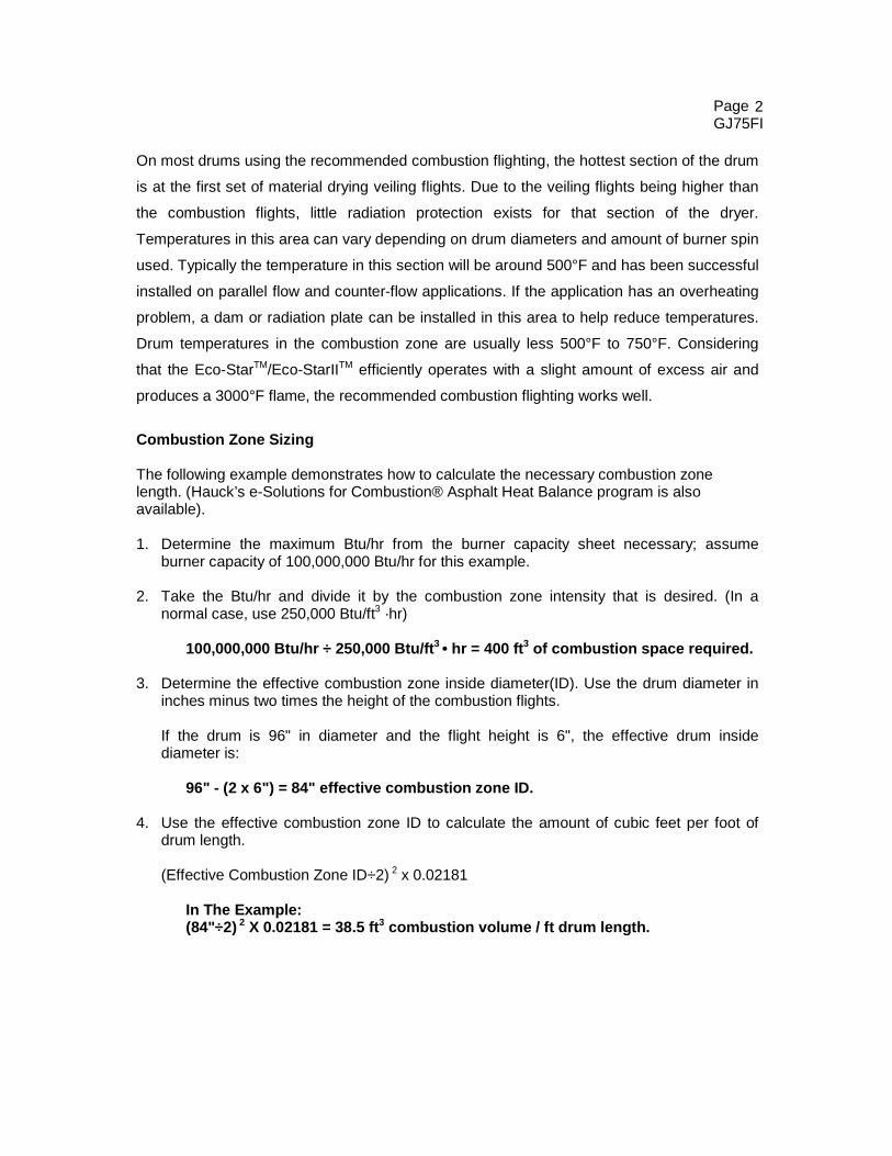
Combustion Zone Sizing The following example demonstrates how to calculate the necessary combustion zone length. (Hauck’s e-Solutions for Combustion® Asphalt Heat Balance program is also available). 1. Determine the maximum Btu/hr from the burner capacity sheet necessary; assume
burner capacity of 100,000,000 Btu/hr for this example. 2. Take the Btu/hr and divide it by the combustion zone intensity that is desired. (In a
normal case, use 250,000 Btu/ft3 ·hr) 100,000,000 Btu/hr ÷ 250,000 Btu/ft3 • hr = 400 ft3 of combustion space required. 3. Determine the effective combustion zone inside diameter(ID). Use the drum diameter in
inches minus two times the height of the combustion flights.
If the drum is 96" in diameter and the flight height is 6", the effective drum inside diameter is: 96" - (2 x 6") = 84" effective combustion zone ID.
4. Use the effective combustion zone ID to calculate the amount of cubic feet per foot of
drum length.
(Effective Combustion Zone ID÷2) 2 x 0.02181 In The Example: (84"÷2) 2 X 0.02181 = 38.5 ft3 combustion volume / ft drum length.
3
Page GJ75FI
5. To determine the drum length required in feet, divide the combustion volume required (see step 2) by the cubic feet per foot of drum (Step 4).
For most applications this method produces good results, however for unusual
configurations or firing rates the flame lengths for the burners should be checked to ensure
that the planned combustion length and diameter is within the burner’s capability. (see
attached flame length tables).
Combustion Zone Produces Flame Intensity The Eco-StarTM/Eco-StarIITM is capable of high flame intensities. Flame intensity is defined
as Btu/hr ·ft3 of combustion space. This is determined by finding the Btu/hr firing rate that is
used and dividing it by the cubic feet of combustion space available. A normal maximum
flame zone intensity is 250,000 to 300,000 Btu/ft3 on natural gas and 175,000 to 250,000
Btu/ft3 on oil firing. Propane fired burners require 150,000 to 200,000 Btu/ft3. This intensity
can be higher under ideal conditions, or lower if pollution requirements necessitate very low
CO and THC levels. Ideal conditions mean that the burner chosen will run near its
maximum firing capability. Running the burner near its maximum capacity will allow
for higher efficiency, promote optimum mixing and result in lowest emissions. Due to
the variety of rotary drying applications, the proper number to use for sizing the combustion
zone is based somewhat on experience. It is a good idea to consider normal available flame
shapes for the size burner that is desired as well.
When sizing a burner and combustion zone for stringent emission regulation applications,
allow extra space for the flame to fully combust. Applications that require low CO and THC
benefit from larger combustion zones. In situations where (flue gas recirculation) is added to
reduce NOx, a larger combustion zone is also helpful. Combustion intensities in these cases
will be lower. Do not be concerned when removing several more feet of veiling flighting to
complete the combustion flighting as the new combustion flights will allow extra material
heating and drying from conductive heat transfer. Veiling flights can be added to make up
the difference in the balance of the drum (Consult Hauck).
4
Page GJ75FI
For example, consider an ESII-100 firing natural gas at 100 MMbtu/hr in an 8 ft diameter
drum. First, use 250,000 Btu/ft3 as the combustion intensity and then check to see if the
flame fits into the available combustion zone. This is a 9 ft long x 5 ft diameter flame @ 30°
spin in an 8 ft. diameter dryer which appears reasonable. Consideration must be made for
combustion flights. For instance, an 8 ft. drum becomes 7 ft if the combustion flights are 6
inches high. Thus the required combustion length using 7 ft diameter = 10.4 ft long (see
combustion zone sizing example). This arrangement will probably produce 300 to 600 ppm
of CO @ 7% 02. In a 10 ft diameter drum, the calculated combustion zone would be too short
at only 6.3 ft long. A length of 6.3 ft is shorter than the recorded flame length at full spin of
8ft. long for natural gas (See Flame Dimension sheets for the Eco-StarTM/Eco-StarIITM). If on
the same example the CO requirement was below 500 ppm, then the combustion zone
should be more generous to ensure that all the flame is contained in the non-veiling zone.
The maximum flame length must be checked against the calculated combustion zone length.
Burner mounting is determined by the type of plant and the fuel used. The Eco-StarTM/ Eco-
StarIITM comes standard with a nose that can be inserted into most drums to prevent
overheating of the breech plate. Insertion depth depends on the fuel and the configuration of
the inside of the dryer. If there are any inside projections, such as an overhead discharge,
make sure the burner is inserted far enough to be even with or slightly past the overhead
discharge. On oil, the burner may need to be inserted 6 to 12 inches past the internal
discharge chute, or on gas, it is possible to insert the burner even with the chute. For dryers
without internal projections, the Eco-StarTM/Eco-StarIITM only needs to be installed 12 to 18
inches past the breech plate on gas or propane firing. Oil fired burners should be inserted 18
to 24 inches from the breech plate. These distances, on most plants, produce acceptable
breech plate temperatures in the 300-550°F range except on extremely well sealed plants, or
when the high swirl (Shortest) flame is required. Breech overheating can be usually
remedied by sliding the burner further into the drum or by installing stainless steel radiation
shielding plates on the inside of the breech plate if the burner cannot be moved into the
drum. Make provisions to slide the burner into the dryer when installing the burner on the
drum.
5
Page GJ75FI
Please Note The Following Important Considerations:
1. Flight spacing of 1/4 inch between flights is important in keeping the combustion zone drum shell temperatures to a minimum. The drum shell should not be exposed directly to the flame. If the drum is exposed, as in the case of uneven flight spacing or missing flights the drum shell temperature in that area could run over 600°F.
2. Dams must be used on the upstream side of the flight. The dams on the
upstream end of the flights allow a small amount of material to go under the flight thru the dam openings provided. Each set of flights will have a dam upstream of it.
Flame Shape For Eco-StarTM/Eco-StarIITM Burners (Dimensions in Feet)
1. Altitude limitation for 36 osi blower is 2500 ft for heavy oil and 4500 ft for light fuel oil. Above these altitudes, use blower altitude kit or compressed air atomization; consult Hauck. For ES25 and ES50, the blower altitude kit is the only available option for high altitude installations. 2. Atomizing blower pressure required at sea level can be used to select appropriate blower pressure required at sea level in order to achieve the equivalent sea level capacity at a given altitude.