International Journal of Applied Engineering Research ISSN 0973-4562 Volume 12, Number 10 (2017) pp. 2136-2149
© Research India Publications. http://www.ripublication.com
2136
Economical Short Rectangular Reinforced Concrete Column Design under
Combined Axial Load plus Uniaxial Bending Using STAAD Pro
Talib Abdul Jabbar AL-Eyssawi 0000-0002-7949-3324
Lecturer, Babylon Technical Institute, Al-Furat Alawsat Technical University, Babylon, Iraq.
Abstract
The intention of this study is to minimize the cost of short
rectangular reinforced concrete column design under
combined axial loads plus uniaxial bending and approach
the economical column design without prior knowledge of
optimization. The total cost of column includes cost of
concrete, reinforcement, and formwork, whereas the ties
cost incorporated in the reinforcement cost. The design
variables considered in this study are the loading, width of
column, height to width ratio, unit cost of concrete and unit
cost of formwork.
STAAD Pro V8i software has been used to design all
columns. All calculations are done based on elastic
analysis and the ultimate strength method of design as per
ACI 318M-14 code requirements for axial loads and
bending moments.
The results of economical columns total costs database
indicate that the average cost ratio of concrete,
reinforcement and formwork to total cost are 28%, 36% and
36% respectively, whereas ties cost constitutes 7% of the
total cost.
Economical column design can be obtained from several
iterations in total cost calculations, and more trials for
section dimensions of the column lead to more economical
column design. Economical column design can be
approached as the column cross section has height to width
ratio in the range of 1 to 1.25 and reinforcement ratio in the
range of 1% to 2.5% at the same time.
Keywords: Economical column, cost, reinforced concrete design,
short column, axial loads plus uniaxial bending, STAAD Pro
Notations
= total area of longitudinal reinforcement, mm2
Af = area of formwork, m2
= width of column, mm
Cc = cost of concrete, US$
Cf = cost of formwork, US$
Cs = cost of steel reinforcement, US$
Ct = total cost, US$
e = eccentricity distance, mm
= specified compressive strength of concrete,
MPa
= specified yield strength of reinforcement, MPa
h = height of column, mm
lc = length of column, m
Mn = nominal flexural strength at section, kN.m
Mu = factored bending moment at section, kN.m
Pn = nominal axial compressive strength of
member, kN
Pu = factored axial compressive force, kN
Uc = unit cost of concrete, US$/m3
Uf = unit cost of formwork, US$/m2
Us = unit cost of steel reinforcement, US$/kg
Vc = volume of concrete, m3
Ws = weight of steel reinforcement, kg
Wls = weight of longitudinal steel reinforcement, kg
Wts = weight of transverse steel reinforcement (ties),
kg
k = effective length factor for compression
members
ϕ = strength reduction factor
ρ = ratio of Ast to bh
= net tensile strain in extreme layer of
longitudinal tension reinforcement at nominal
strength ACI 318-14)
INTRODUCTION
Today and from economic climate point view, the structural
designer should study the cost effect of design very
carefully. Design should attain economy of materials in the
structure, but over-refinement may produce a large number
of various sizes of members in the structure, and the cost of
labour will increase. Also the time of design should not be
very long period [1].
Sustainability design has been required for reinforced
concrete structures in addition to strength, serviceability,
and durability [2]. In general, sustainable design is
acceptable if a compromise between economic
considerations, social values, and environmental impacts,
and competent structural designers can decrease the cost of
concrete and steel reinforcement required for various
members of the structure [3].
International Journal of Applied Engineering Research ISSN 0973-4562 Volume 12, Number 10 (2017) pp. 2136-2149
© Research India Publications. http://www.ripublication.com
2137
For economical column design, tied columns are more
economical than spiral columns, especially if square or
rectangular cross sections are utilized [4]. Columns with a
height to width ratio between 1 to 2 are commonly used
[5, 6]. Most studies of optimal columns total costs used only
the square columns with a height to width ratio equal 1 [8, 9,
10].
Short columns are stocky members with little flexibility, fail
due to initial material failure. The slender effect of short
columns may be neglected, and can be designed without
strength reduction factor [4, 11, 12].
Reinforcement is quite expensive and main factor in
reinforced concrete columns total costs [4]. It is more
economical to use large column section dimensions with
small quantity of steel reinforcement because concrete is
more cost effective than steel reinforcement for resisting the
axial compressive load. The most economical columns have
reinforcement ratios in the range of 1% to 2% [3, 13], and
tied columns seldom have reinforcement ratios greater than
3 percent [3]. The failure of ordinary reinforced concrete
columns depends on concrete compression capacity and
reinforcement yield stress. The longitudinal steel
reinforcement has great effect on the load capacity of
column [14].
Formwork accounts about 40% of the total cost of a
concrete project construction and determine its success
[15]. Formwork is very expensive, and in the United States,
the costs of formwork constitute one-third to two-thirds of
the total cost of a reinforced concrete structure, with average
costs of about 50%. To have better economy of reinforced
concrete structures, the main emphasis is on reducing
formwork costs [4]. It is very important to include the costs
of formwork, when the cost of structural concrete frames is
calculated [13].
The columns cost database were studied using different unit
costs of concrete, steel and formwork of 100 $/m3, 1 $/kg
and 25 $/m2 respectively in the first case, 110 $/m3, 2.1 $/kg
and 27 $/m2, respectively in the second case to make the
total cost component the minimum based on the harmony
search algorithm [16]. Also, columns cost database were
studied using different unit costs of concrete, steel and
formwork of 54 $/m3, 0.55 $/kg and 50.5 $/m2 respectively
to minimize the total cost of material and construction of
reinforced concrete frames base on the big bang-big crunch
algorithm [8]. Meta-heuristic algorithms was used to
minimize the total cost of material and construction of
reinforced concrete frames. The columns cost database were
studied using different unit costs of concrete, steel and
formwork of 105 $/m3, 0.9 $/kg and 92 $/m2 respectively
[9].
The aim of this study is to minimize the total cost of short
rectangular reinforced concrete column design under
combined axial loads plus uniaxial bending and approach
the economical column design. The total cost of column
includes cost of concrete, reinforcement, and formwork,
whereas the transverse reinforcement (ties) cost incorporated
in the reinforcement cost. STAAD Pro V8i software [17]
and EXCEL spreadsheet [4] have been used to design all
columns as per ACI 318M-14 code requirements for axial
loads and bending moments. STAAD Pro V8i. is one of the
most famous structural engineering softwares used for 3D
model generation, analysis and multi-material design [18].
STAAD Pro is very easy to learn and work, accurate for
both analysis and design, and one of preferable softwares
used for the design of structures [19].
Computer programs such as Staad is used to determine
iteratively [11] the total cost of different short rectangular
reinforced concrete columns designed under combined axial
loads plus uniaxial bending.
SCOPE AND METHODOLOGY
a. Objective
This study aims to minimize the cost of short rectangular
reinforced concrete column design under combined axial
loads plus uniaxial bending and approach the economical
column design without prior knowledge of optimization.
The economical column design has standard column cross
section, and its total cost close to lowest value.
The total cost of column includes material, labor and
equipment costs of concrete, reinforcement, and formwork,
whereas the reinforcement cost includes the costs of
longitudinal and transverse reinforcement. The total cost of
the column can be calculated by the following equation,
Ct=Cc + Cs + Cf ( 1a )
Ct=Vc . Uc+ Ws . Us+ Af . Uf ( 1b )
Ct=(b . h . lc) Uc+ (Wls + Wts) Us+ 2lc (b+h) Uf ( 1c )
b. Formulation of the problem
b1. Solution procedure
Both longitudinal and transverse reinforcement (ties) of each
column can be determined by using STAAD Pro V8i
software in the design of all columns. All calculations are
performed based on elastic analysis and the ultimate
strength method of design as per ACI 318M-14 code
requirements for axial loads and bending moments.
b2. Design variables
The design variables considered in this study are the loading
(Pu and Mu), width of column (b), height to width ratio (h/b),
unit cost of concrete (Uc) and unit cost of formwork (Uf).
b3. Design of column subjected to axial load and uniaxial
bending
Designers resort always to computer programs, interaction
diagrams, or tables for design calculations of reinforced
concrete columns. [4]. STAAD Pro V8i software has been
used to design all columns as per ACI 318M-14 code
requirements for axial loads and bending moments. The
International Journal of Applied Engineering Research ISSN 0973-4562 Volume 12, Number 10 (2017) pp. 2136-2149
© Research India Publications. http://www.ripublication.com
2138
ultimate axial load and ultimate bending can be calculated
from the following equations,
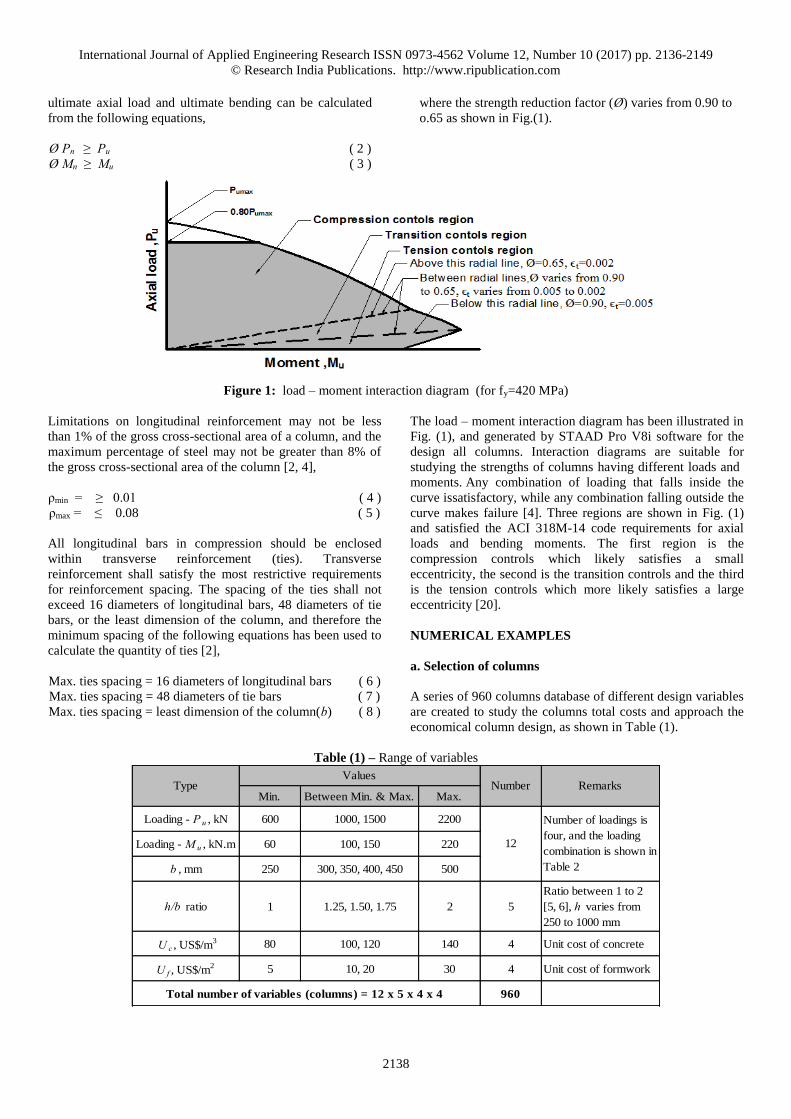
Ø Pn ≥ Pu ( 2 )
Ø Mn ≥ Mu ( 3 )
where the strength reduction factor (Ø) varies from 0.90 to
o.65 as shown in Fig.(1).
Figure 1: load – moment interaction diagram (for fy=420 MPa)
Limitations on longitudinal reinforcement may not be less
than 1% of the gross cross-sectional area of a column, and the
maximum percentage of steel may not be greater than 8% of
the gross cross-sectional area of the column [2, 4],
ρmin = ≥ 0.01 ( 4 ) ρmax = ≤ 0.08 ( 5 )
All longitudinal bars in compression should be enclosed
within transverse reinforcement (ties). Transverse
reinforcement shall satisfy the most restrictive requirements
for reinforcement spacing. The spacing of the ties shall not
exceed 16 diameters of longitudinal bars, 48 diameters of tie
bars, or the least dimension of the column, and therefore the
minimum spacing of the following equations has been used to
calculate the quantity of ties [2],
Max. ties spacing = 16 diameters of longitudinal bars ( 6 )
Max. ties spacing = 48 diameters of tie bars ( 7 )
Max. ties spacing = least dimension of the column(b) ( 8 )
The load – moment interaction diagram has been illustrated in
Fig. (1), and generated by STAAD Pro V8i software for the
design all columns. Interaction diagrams are suitable for
studying the strengths of columns having different loads and
moments. Any combination of loading that falls inside the
curve issatisfactory, while any combination falling outside the
curve makes failure [4]. Three regions are shown in Fig. (1)
and satisfied the ACI 318M-14 code requirements for axial
loads and bending moments. The first region is the
compression controls which likely satisfies a small
eccentricity, the second is the transition controls and the third
is the tension controls which more likely satisfies a large
eccentricity [20].
NUMERICAL EXAMPLES
a. Selection of columns
A series of 960 columns database of different design variables
are created to study the columns total costs and approach the
economical column design, as shown in Table (1).
Table (1) – Range of variables
Min. Between Min. & Max. Max.
Loading - P u , kN 600 1000, 1500 2200
Loading - M u , kN.m 60 100, 150 220
b , mm 250 300, 350, 400, 450 500
h/b ratio 1 1.25, 1.50, 1.75 2 5
Ratio between 1 to 2
[5, 6], h varies from
250 to 1000 mm
U c , US$/m3 80 100, 120 140 4 Unit cost of concrete
U f , US$/m2 5 10, 20 30 4 Unit cost of formwork
960
12
Number of loadings is
four, and the loading
combination is shown in
Table 2
Total number of variables (columns) = 12 x 5 x 4 x 4
TypeValues
RemarksNumber
International Journal of Applied Engineering Research ISSN 0973-4562 Volume 12, Number 10 (2017) pp. 2136-2149
© Research India Publications. http://www.ripublication.com
2139
The loading combination of all columns is illustrated in
Table(2), whereas the axial compressive loads (Pu) are
600 kN, 1000 kN, 1500 kN, 2200 kN and bending
moments (Mu) are 60 kN.m, 100 kN.m, 150 kN.m,
220 kN.m respectively. All variables are chosen in such a way
that satisfy the strength design method requirements of the
ACI code for axial loads and bending moments.
For all columns, the length of column (lc), compressive
strength of concrete ( ), yield stress of steel ( ), clear over
of reinforcement, unit weight of reinforced concrete, unit
weight of steel reinforcement, cost of reinforcement (Us) and
the effective length factor (k) are 4 m, 21 MPa, 420 MPa,
40 mm, 24 kN/m3 [2, 4, 21], 7850 kg/m3 [6, 22], 1 US$/kg
[16] and 1 respectively. The sizes of the longitudinal bars
are : 12 mm, 16 mm, 20 mm, 25 mm and 32 mm, while the
size of transverse bar (ties) is 10 mm, which are commonly
used and available at the market.
Table (2) – Loading combination
P u ,
kN
M u ,
kN.mMin.
Between Min.
& Max.Max.
1 600 60 250 300, 350 400 320 1 to 320 4
2 1000 100 300 350 400 240 321 to 560 3
3 1500 150 350 ---------- 400 160 561 to 720 2
4 2200 220 400 450 500 240 721 to 960 3
960 12
Width of column (b ), mm
RemarksLoading
case
Total number of columns = 320 + 240 +160 + 240
Sequence of
columns
All e is equal to 100
mm, and less than
2e/d to satisfy the
compression controls
region [26], minimum
b equals to 250 mm
is preferable [3]
No. of
variables
Loading valueNo. of
columns
b. Results and discussions
STAAD Pro V8i software and EXCEL spreadsheet according
to ACI 318M-14 code requirements for axial loads and
bending moments have been used to calculate the columns
costs. Eq. (1) provides the columns total costs as per the
column design limitations of Eqs. (2) through (8).
Staad Pro includes the column self-weight based on the input
values for the width (b), height (h) and length (lc) in order to
calculate the accurate loading. The reinforcement arrangement
is simple, easily achievable solution [23], and economical
arrangements [4] for both longitudinal and transverse
reinforcement (ties). The longitudinal bar locations [4, 10, 12]
are either equal bars on columns two end faces or equal bars
on columns all four faces, so that lowest amount of the
reinforcement bars is used to satisfy the design requirements.
All the design results are existing in the compression controls
region of Fig. (1). Appendixes A, B and C indicate STAAD
Pro V8i design output file, concrete design and design report
for columns 731, 851 and 956 respectively which are shown
in Table (3).
b1. Economical column design
Table (3) reveals the database of the columns total costs. The
total cost includes concrete, reinforcement for both
longitudinal and transverse (ties) and formwork costs. For the
column of same loading, same width (b) and same unit costs,
there is a cycle of calculations for different heights with
different amount of reinforcement. Several iterations lead to
the economical column design [4], and more trials for column
section dimensions lead to more economical column design.
International Journal of Applied Engineering Research ISSN 0973-4562 Volume 12, Number 10 (2017) pp. 2136-2149
© Research India Publications. http://www.ripublication.com
2140
Table (3) – Database of columns total costs
l c , mb ,
mm
h ,
mmh/b
V c ,
m3
U c ,
$/m3
C c , $ ρW ls ,
Kg
W ts ,
Kg
W s ,
Kg
U s ,
$/kgC s , $
A f ,
m2
U f ,
$/m2
C f , $
1 1 4 250 250 1.00 0.25 80 20.0 6.28 123.3 9.2 132.5 1.00 132.5 4.00 5 20.0 172.5
2 1 4 250 312.5 1.25 0.31 80 25.0 4.12 101.0 10.5 111.5 1.00 111.5 4.50 5 22.5 159.0
---- ---- ---- ---- ---- ---- ---- ---- ---- ---- ---- ---- ---- ---- ---- ---- ---- ---- ----
7 1 4 300 375 1.25 0.45 80 36.0 1.12 39.5 10.6 50.0 1.00 50.0 5.40 5 27.0 113.0
---- ---- ---- ---- ---- ---- ---- ---- ---- ---- ---- ---- ---- ---- ---- ---- ---- ---- ----
306 1 4 300 300 1.00 0.36 140 50.4 1.79 50.5 10.6 61.1 1.00 61.1 4.80 30 144.0 255.5
---- ---- ---- ---- ---- ---- ---- ---- ---- ---- ---- ---- ---- ---- ---- ---- ---- ---- ----
387 2 4 350 437.5 1.25 0.61 100 61.3 1.05 50.5 14.3 64.8 1.00 64.8 6.30 5 31.5 157.6
---- ---- ---- ---- ---- ---- ---- ---- ---- ---- ---- ---- ---- ---- ---- ---- ---- ---- ----
447 2 4 350 437.5 1.25 0.61 120 73.5 1.05 50.5 14.3 64.8 1.00 64.8 6.30 5 31.5 169.8
---- ---- ---- ---- ---- ---- ---- ---- ---- ---- ---- ---- ---- ---- ---- ---- ---- ---- ----
577 3 4 400 500 1.25 0.80 80 64.0 1.13 71.0 21.7 92.8 1.00 92.8 7.20 10 72.0 228.8
---- ---- ---- ---- ---- ---- ---- ---- ---- ---- ---- ---- ---- ---- ---- ---- ---- ---- ----
706 3 4 400 400 1.00 0.64 140 89.6 2.36 118.4 11.8 130.2 1.00 130.2 6.40 20 128.0 347.8
---- ---- ---- ---- ---- ---- ---- ---- ---- ---- ---- ---- ---- ---- ---- ---- ---- ---- ----
731 4 4 500 500 1.00 1.00 80 80.0 1.09 85.3 24.3 109.6 1.00 109.6 8.00 5 40.0 229.6
---- ---- ---- ---- ---- ---- ---- ---- ---- ---- ---- ---- ---- ---- ---- ---- ---- ---- ----
851 4 4 500 500 1.00 1.00 120 120.0 1.09 85.3 24.3 109.6 1.00 109.6 8.00 5 40.0 269.6
---- ---- ---- ---- ---- ---- ---- ---- ---- ---- ---- ---- ---- ---- ---- ---- ---- ---- ----
956 4 4 500 500 1.00 1.00 140 140.0 1.09 85.3 24.3 109.6 1.00 109.6 8.00 30 240.0 489.6
---- ---- ---- ---- ---- ---- ---- ---- ---- ---- ---- ---- ---- ---- ---- ---- ---- ---- ----
960 4 4 500 1000 2.00 2.00 140 280.0 1.01 157.8 23.1 180.9 1.00 180.9 12.00 30 360.0 820.9
Col.
No.
Load.
case
Column dimensions Concrete Steel reinforcement Formwork
C t , $
For each column of a specified axial load, bending moment,
unit cost of concrete and unit cost of formwork, there is an
economical total cost depending on the column cross section
and contribution of unit cost of concrete, unit cost of steel
reinforcement and the unit cost of formwork in the column
total cost.
Table (4) shows the lower and upper bounds [7] of the
economical columns total costs for each column loading. The
lower bound is assigned for unit cost of concrete and unit cost
of formwork 80 $/m3 and 5 $/m2 respectively, while the upper
bound is assigned for unit cost of concrete and unit cost of
formwork 140 $/m3 and 30 $/m2 respectively.
Table (4) – Lower and upper and bounds of economical columns total costs
l c , mb ,
mm
h ,
mmh/b
V c ,
m3
U c ,
$/m3
C c , $ ρW ls ,
Kg
W ts ,
Kg
W s ,
Kg
U s ,
$/kgC s , $
A f ,
m2
U f ,
$/m2
C f , $
7 1 4 300 375 1.25 0.45 80 36.0 1.12 39.5 10.6 50.0 1.00 50.0 5.40 5 27.0 113.0
301 1 4 300 300 1.00 0.36 140 50.4 1.79 50.5 10.6 61.1 1.00 61.1 4.80 30 144.0 255.5
327 2 4 350 437.5 1.25 0.61 80 49.0 1.05 50.5 14.3 64.8 1.00 64.8 6.3 5 31.5 145.3
551 2 4 350 350 1.00 0.49 140 68.6 2.05 78.9 10.2 89.2 1.00 89.2 5.6 30 168.0 325.8
567 3 4 400 500 1.25 0.80 80 64.0 1.13 71.0 21.7 92.8 1.00 92.8 7.2 5 36.0 192.8
716 3 4 400 400 1.00 0.64 140 89.6 2.36 118.4 11.8 130.2 1.00 130.2 6.4 30 192.0 411.8
731 4 4 500 500 1.00 1.00 80 80.0 1.09 85.3 24.3 109.6 1.00 109.6 8 5 40.0 229.6
956 4 4 500 500 1.00 1.00 140 140.0 1.09 85.3 24.3 109.6 1.00 109.6 8 30 240.0 489.6
Col.
No.
Load.
case
Column dimensions Concrete Steel reinforcement Formwork
C t , $
International Journal of Applied Engineering Research ISSN 0973-4562 Volume 12, Number 10 (2017) pp. 2136-2149
© Research India Publications. http://www.ripublication.com
2141
Table (5) shows the cost ratio of concrete, reinforcement and
formwork to total cost are 28%, 36% and 36% respectively,
while the ties cost constitutes 7% of the total cost.
Table (5) – Cost ratio of economical columns total costs
Concrete Formwork
U c , $/m3 U f , $/m
2 Concrete/
Total
Steel/
Total
Formwork/
Total
Ties/
Total
7 1 80 5 32% 44% 24% 9%
301 1 140 30 20% 24% 56% 4%
327 2 80 5 34% 45% 22% 10%
551 2 140 30 21% 27% 52% 3%
567 3 80 5 33% 48% 19% 11%
716 3 140 30 22% 32% 47% 3%
731 4 80 5 35% 48% 17% 11%
956 4 140 30 29% 22% 49% 5%
33% 46% 20% 10%
23% 26% 51% 4%
28% 36% 36% 7%
Cost ratio
Average of lower bounds of economical
columns total costs
Average of upper bounds of economical
columns total costs
Average of economical
columns total costs
Col.
No.
Load.
caseRemarks
Ties cost is
a part of
steel cost
b2. Effect of reinforcement ratio
The longitudinal reinforcement ratios (ρ) for different
columns varies from 1% to 6.5%, depending on the
magnitude of axial load, moment and the column cross
sectional area. Fig. (2) illustrates the relationship between
column total cost and reinforcement ratio.
Figure 2: Relationship between column total cost and reinforcement ratio
It is appeared that economical column total cost can be
occurred when the reinforcement ratios varies from 1% to
2.5%. This trend to use a minimum reinforcement ratio (ρ) is
due to the fact of higher cost of steel [22] and large amount of
reinforcement used in columns compared with beams [16].
If small percentages of steel are used in columns, this will
avoid crowding of the steel reinforcement, mainly at splices,
and concrete getting down into the forms smoothly [4].
Structural designers think that using steel percentages fairly
low will result in good economy [4]. Also, saving the quantity
International Journal of Applied Engineering Research ISSN 0973-4562 Volume 12, Number 10 (2017) pp. 2136-2149
© Research India Publications. http://www.ripublication.com
2142
of reinforcement will reduce the carbon footprint, and increase
the sustainability of reinforced concrete construction [10, 24].
b3. Effect of height to width ratio
The height to width ratio (h/b) for different columns are 1,
1.25, 1.50, 1.75 and 2. Fig. (3) illustrates the relationship
between column total cost and h/b ratio.
Figure 3: Relationship between column total cost and h/b ratio
It is clearly appeared from the above figure and Table (4) that
economical column total cost can be happened when the h/b
ratios are either 1 or 1.25, while most studies of optimal
columns total costs used only the square columns [8, 9, 10].
The h/b ratio of the economical column total cost varies in the
range of 1 to 1.25 due to contribution of unit cost of concrete,
unit cost of steel reinforcement and unit cost of formwork in
the column total cost.
b4. Effect of formwork unit cost
The formwork unit cost (Uf) for different columns are 5 $/m2,
10 $/m2, 20 $/m2 and 30 $/m2. Fig. (4) illustrates the
relationship between economical column total cost and
formwork unit cost.
Figure 4: Relationship between economical column total cost and formwork unit cost
It is obvious that there is a tangible increase in the economical
column total cost when the formwork unit cost is increased.
The average increases in the economical columns total costs
are 18%, 53% and 87% when the formwork unit cost (Uf)
increases from 5 $/m2 to 10 $/m2, 20 $/m2 and 30 $/m2
respectively. The formwork is more cost effective [13] than
concrete and the formwork unit cost is increased rapidly
compared with the concrete unit cost whereas the formwork
unit cost is increased six times while the concrete unit cost is
increased 1.75 times only through the cost comparison
between the upper and lower bounds of unit cost of formwork
and unit cost of concrete.
For economy in column design and within normal maximum
building heights, about 60 stories or 180 m, increased speed of
construction and saving in formwork will save more than the
cost of the excessconcrete [25].
International Journal of Applied Engineering Research ISSN 0973-4562 Volume 12, Number 10 (2017) pp. 2136-2149
© Research India Publications. http://www.ripublication.com
2143
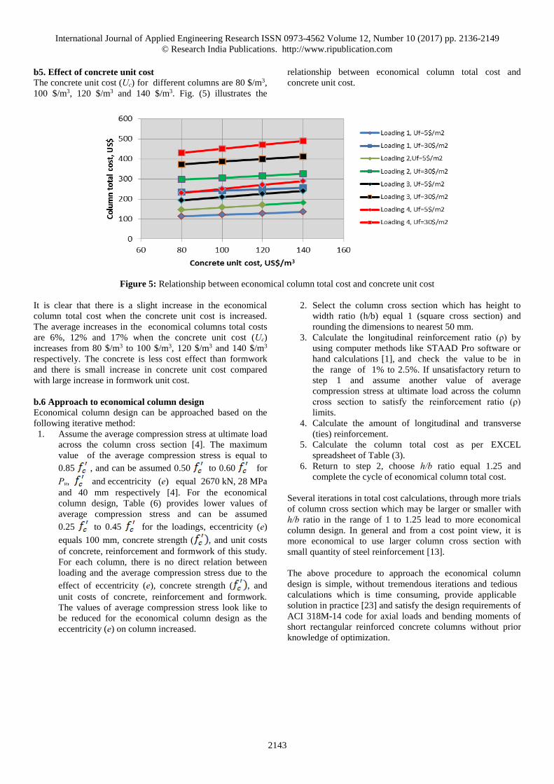
b5. Effect of concrete unit cost
The concrete unit cost (Uc) for different columns are 80 $/m3,
100 $/m3, 120 $/m3 and 140 $/m3. Fig. (5) illustrates the
relationship between economical column total cost and
concrete unit cost.
Figure 5: Relationship between economical column total cost and concrete unit cost
It is clear that there is a slight increase in the economical
column total cost when the concrete unit cost is increased.
The average increases in the economical columns total costs
are 6%, 12% and 17% when the concrete unit cost (Uc)
increases from 80 $/m3 to 100 $/m3, 120 $/m3 and 140 $/m3
respectively. The concrete is less cost effect than formwork
and there is small increase in concrete unit cost compared
with large increase in formwork unit cost.
b.6 Approach to economical column design
Economical column design can be approached based on the
following iterative method:
1. Assume the average compression stress at ultimate load
across the column cross section [4]. The maximum
value of the average compression stress is equal to
0.85 , and can be assumed 0.50 to 0.60 for
Pu, and eccentricity (e) equal 2670 kN, 28 MPa
and 40 mm respectively [4]. For the economical
column design, Table (6) provides lower values of
average compression stress and can be assumed
0.25 to 0.45 for the loadings, eccentricity (e)
equals 100 mm, concrete strength ( , and unit costs
of concrete, reinforcement and formwork of this study.
For each column, there is no direct relation between
loading and the average compression stress due to the
effect of eccentricity (e), concrete strength ( , and
unit costs of concrete, reinforcement and formwork.
The values of average compression stress look like to
be reduced for the economical column design as the
eccentricity (e) on column increased.
2. Select the column cross section which has height to
width ratio (h/b) equal 1 (square cross section) and
rounding the dimensions to nearest 50 mm.
3. Calculate the longitudinal reinforcement ratio (ρ) by
using computer methods like STAAD Pro software or
hand calculations [1], and check the value to be in
the range of 1% to 2.5%. If unsatisfactory return to
step 1 and assume another value of average
compression stress at ultimate load across the column
cross section to satisfy the reinforcement ratio (ρ)
limits.
4. Calculate the amount of longitudinal and transverse
(ties) reinforcement.
5. Calculate the column total cost as per EXCEL
spreadsheet of Table (3).
6. Return to step 2, choose h/b ratio equal 1.25 and
complete the cycle of economical column total cost.
Several iterations in total cost calculations, through more trials
of column cross section which may be larger or smaller with
h/b ratio in the range of 1 to 1.25 lead to more economical
column design. In general and from a cost point view, it is
more economical to use larger column cross section with
small quantity of steel reinforcement [13].
The above procedure to approach the economical column
design is simple, without tremendous iterations and tedious
calculations which is time consuming, provide applicable
solution in practice [23] and satisfy the design requirements of
ACI 318M-14 code for axial loads and bending moments of
short rectangular reinforced concrete columns without prior
knowledge of optimization.
International Journal of Applied Engineering Research ISSN 0973-4562 Volume 12, Number 10 (2017) pp. 2136-2149
© Research India Publications. http://www.ripublication.com
2144
Table (6) – Preliminary estimates of average compression stress at ultimate load
across the economical column cross section
Concrete Formwork
P u ,
kN
M u ,
kN.mb , mm h , mm h/b U c , $/m
3 U f , $/m2
7 1 600 60 300 375 1.25 80 5 0.27 0.25fc'
301 1 600 60 300 300 1.00 140 30 0.33 0.32fc'
327 2 1000 100 350 437.5 1.25 80 5 0.23 0.31fc'
551 2 1000 100 350 350 1.00 140 30 0.29 0.39fc'
567 3 1500 150 400 500 1.25 80 5 0.20 0.36fc'
716 3 1500 150 400 400 1.00 140 30 0.25 0.45fc'
731 4 2200 220 500 500 1.00 80 5 0.20 0.42fc'
956 4 2200 220 500 500 1.00 140 30 0.20 0.42fc'
0.25 fc' to
0.45 fc'
Loading value
e/h
Preliminary estimates for average compression stress
Load.
case
Average
compressiom
stress
Col.
No.
Column dimensions
CONCLUSIONS
Based on the costs results obtained by using STAAD Pro software as per ACI 318M-14 code, the following conclusions may be
drawn for the economical column design:
1. The average cost ratio of concrete, reinforcement and formwork to total cost are 28%, 36% and 36% respectively,
whereas the ties cost constitutes 7% of the total cost.
2. The reinforcement ratio (ρ) is in the range of 1% to 2.5%.
3. The height to width ratio (h/b) ratio is in the range of 1 to 1.25 .
4. The formwork is more cost effective than concrete, and the average increases in the economical columns total costs are
18%, 53% and 87% when the formwork unit cost (Uf) increases from 5 $/m2 to 10 $/m2, 20 $/m2 and 30 $/m2
respectively.
5. The formwork is more cost effective than concrete, and the average increases in the economical columns total costs are
18%, 53% and 87% when the formwork unit cost (Uf) increases from 5 $/m2 to 10 $/m2, 20 $/m2 and 30 $/m2
respectively.
6. The average increases in the economical columns total costs are 6%, 12% and 17% when the concrete unit cost (Uc)
increases from 80 $/m3 to 100 $/m3, 120 $/m3 and 140 $/m3 respectively.
REFERENCES
[1] Arya C., 2009, “Design of Structural Elements”,
3rd Ed., Taylor & Francis.
[2] ACI Committee 318, 2014, “Building Code
Requirements for Structural Concrete and
Commentary (ACI 318M-14)”, American
Concrete Institute, Farmington Hills, MI.
[3] Wight J. K. and MacGregor J. G., 2012,
“Reinforced Concrete Mechanics and Design”,
6th Ed., Pearson, Inc., New Jersey, pp. 12-39.
[4] McCormac J. C. and Brown R. H., 2014, “Design
of Reinforced Concrete”, 9th Ed., John Wiley and
Sons, Inc.
[5] Kwak H. G. and Kim J., 2008, “ Optimum Design
of Reinforced Concrete Plane Frames Based on
International Journal of Applied Engineering Research ISSN 0973-4562 Volume 12, Number 10 (2017) pp. 2136-2149
© Research India Publications. http://www.ripublication.com
2145
Predetermined Section Database”, Computer
Aided Design, No. 40, pp. 396 – 408.
[6] Yousif S. T. and Najem R. M., 2014, “Optimum
Cost Design of Reinforced Concrete Columns
Using Genetic Algorithms”, Al-Rafidain
Engineering, Vol. 22, No. 1, pp. 123-141.
[7] Guerra A. and Kiousis P. D., 2006, “Design
Optimization of Reinforced Concrete Structures”,
Journal of Computers and Concrete, Vol. 3, No. 5,
pp. 313-334.
[8] Kaveh A. and Sabzi O., 2012, “Optimal design of
reinforced concrete frames Using big bang-big
crunch algorithm ”, International Journal of Civil
Engineering, Vol. 10, No. 3, pp. 189-200.
[9] Kaveh A. and Sabzi O., 2011, “A comparative
study of two meta-heuristic algorithms for
optimum design of reinforced concrete frames”,
International Journal of Civil Engineering, Vol. 9,
No. 3, pp. 193-206.
[10] Aschheim M., Hernandez-Montes E. and Gil-
Martin L. M., 2008, “ Design of Optimally
Reinforced RC Beam, Column, And Wall
Sections”, Journal of structural Engineering
ASCE, Vol. 134, No. 2, pp. 231 – 239.
[11] Nawy E. G., 2009, “Reinforced Concrete”, 6th
Ed., Pearson Education, Inc., New Jersey.
[12] Nilson A. H., Darwin D. and Dolan C. W., 2010,
“ Design of Concrete Structures”, 14th Ed.,
McGraw-Hill.
[13] Kamara M. E. and Novak L. C., 2011,
“Simplified Design of Reinforced Concrete
Buildings”, 4th Ed., Portland Cement Association,
Old Orchard Road, Skokie, Illinois.
[14] Al-Hassani H. and Hannawayya S., 2104,
“Interaction Diagrams of Short Rectangular RPC
Columns Under Combined Axial Load Plus
Uniaxial Bending”, Journal of Engineering and
Development, Vol. 18, No.4, pp 1-15.
[15] Pawar S. P. and Atterde P. M., 2014,
“Comparative Analysis of Formwork in
Multistory Building”, International Journal of
Research in Engineering and Technology, Vol. 3,
No.9, pp 22-24.
[16] Akin A. and Saka M. P., 2015, “Harmony Search
Algorithm Based Optimum Detailed Design of
Reinforced Concrete Plane Frames Subject to ACI
318-05 Provisions”, Computers and Structures,
Vol. 147, pp 79-95.
International Journal of Applied Engineering Research ISSN 0973-4562 Volume 12, Number 10 (2017) pp. 2136-2149
© Research India Publications. http://www.ripublication.com
2146
[17] Bently Systems Inc., 2015, “Staad. Pro for
windows”, version 8i, release 20.07.11.33,
Pennsylvania.
[18] Thakur S. and Kushwah S. S., 2015, “Cost and
Strength Optimization of ISMB and Hollow
Section of Steel Structures”, International Journal
of Scientific Progress and Research, Vol. 14, No.
2, pp 63-69.
[19] Ramya D. and Sai Kumar A. V., 2015,
“Comparative Study on Design and Analysis of
Multistoreyed Building (g+10) by Staad.Pro and
Etabs Software’s”, International Journal of
Engineering Sciences and Research, Vol. 4, No.
10, pp 125-130.
[20] Jawad A. H., 2006, “Strength Design
Requirements of ACI-318M-02 Code, BS8110,
and EuroCode2 for Structural Concrete: A
Comparative Study”, Journal of Engineering and
Development, Vol. 10, No. 4, pp. 136-150.
[21] Jasim N. A. and Hameed F. M., 2012, “Optimal
Design of Reinforced Concrete Counterfort
Retaining Walls” , Basrah Journal for Engineering
Science, pp. 13-30.
[22] Alreshaid K., Mahdi I. M. and Soliman E., 2004,
“Cost Optimization of Reinforced Concrete
Elements” Asian Journal of Civil Engineering
(Building and Housing), Vol. 5, No. 3-4, pp. 161-
174.
[23] Milajic A., Beljakovic D. and Culic N., 2014,
“Optimal Structural Design Based on
Applicability in Practice”, International Scientific
Conference People, Buildings and Environment,
pp. 306-315.
[24] Gil-Martin L. M, Hernandez-Montes E. and
Aschheim M., 2010, “Optimal Reinforcement of
RC Columns for Biaxial Bending”, Materials and
Structures, No. 43, pp. 1245 – 1256.
[25] Merritt F. S. and Ricketts J. T., 2001, “Building
Design and Construction Handbook”, 6th Ed.,
McGraw-Hill.
[26] Hassoun M. N. and Al-Manaseer A., 2008,
“Structural Concrete”, 4th Ed., John Wiley and
Sons, Inc.
International Journal of Applied Engineering Research ISSN 0973-4562 Volume 12, Number 10 (2017) pp. 2136-2149
© Research India Publications. http://www.ripublication.com
2147
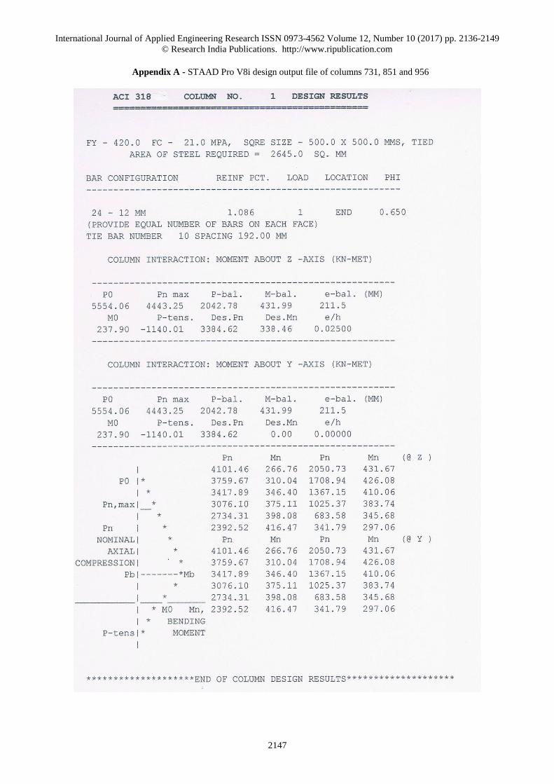
Appendix A - STAAD Pro V8i design output file of columns 731, 851 and 956
International Journal of Applied Engineering Research ISSN 0973-4562 Volume 12, Number 10 (2017) pp. 2136-2149
© Research India Publications. http://www.ripublication.com
2148
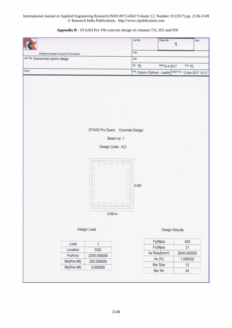
Appendix B - STAAD Pro V8i concrete design of columns 731, 851 and 956
International Journal of Applied Engineering Research ISSN 0973-4562 Volume 12, Number 10 (2017) pp. 2136-2149
© Research India Publications. http://www.ripublication.com
2149
Appendix C - STAAD Pro V8i design report of columns 731, 851 and 956