24
ecoSMRT ® LNG Reliquefaction Alan Duckett – Sales and Technical Director Babcock LGE Process Gastech 2017 – An Improved Reliquefaction System for LNG Carriers
ecoSMRT® LNG ReliquefactionAlan Duckett – Sales and Technical Director
Babcock LGE Process
Gastech 2017 – An Improved Reliquefaction System for LNG Carriers
www.babcockinternational.com
ecoSMRT® – Introduction
2 Gastech 2017 – An Improved Reliquefaction System for LNG Carriers
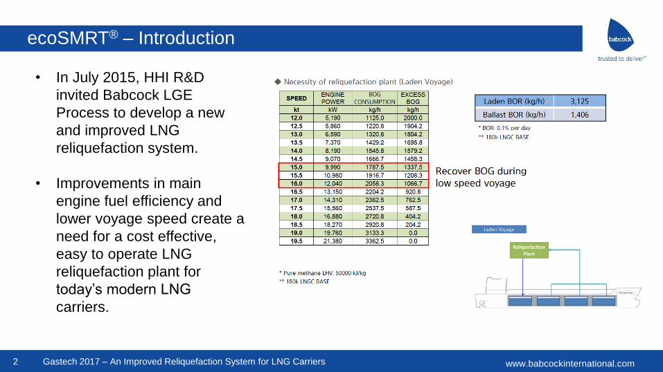
• In July 2015, HHI R&D
invited Babcock LGE
Process to develop a new
and improved LNG
reliquefaction system.
• Improvements in main
engine fuel efficiency and
lower voyage speed create a
need for a cost effective,
easy to operate LNG
reliquefaction plant for
today’s modern LNG
carriers.
www.babcockinternational.com
ecoSMRT® – Design Challenge
3
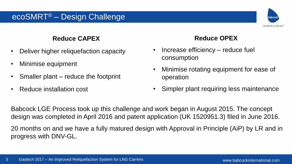
Reduce CAPEX
• Deliver higher reliquefaction capacity
• Minimise equipment
• Smaller plant – reduce the footprint
• Reduce installation cost
Gastech 2017 – An Improved Reliquefaction System for LNG Carriers
Reduce OPEX
• Increase efficiency – reduce fuel
consumption
• Minimise rotating equipment for ease of
operation
• Simpler plant requiring less maintenance
Babcock LGE Process took up this challenge and work began in August 2015. The concept
design was completed in April 2016 and patent application (UK 1520951.3) filed in June 2016.
20 months on and we have a fully matured design with Approval in Principle (AiP) by LR and in
progress with DNV-GL.
www.babcockinternational.com
ecoSMRT® – Existing Reliquefaction Plant
4
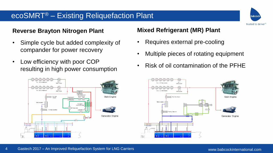
Reverse Brayton Nitrogen Plant
• Simple cycle but added complexity of
compander for power recovery
• Low efficiency with poor COP
resulting in high power consumption
Gastech 2017 – An Improved Reliquefaction System for LNG Carriers
Mixed Refrigerant (MR) Plant
• Requires external pre-cooling
• Multiple pieces of rotating equipment
• Risk of oil contamination of the PFHE
www.babcockinternational.com
ecoSMRT® Main Equipment Selection
5 Gastech 2017 – An Improved Reliquefaction System for LNG Carriers
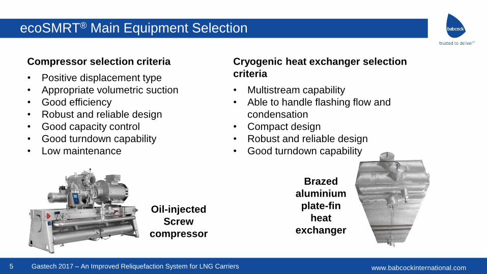
Compressor selection criteria
• Positive displacement type
• Appropriate volumetric suction
• Good efficiency
• Robust and reliable design
• Good capacity control
• Good turndown capability
• Low maintenance
Cryogenic heat exchanger selection
criteria
• Multistream capability
• Able to handle flashing flow and
condensation
• Compact design
• Robust and reliable design
• Good turndown capability
Oil-injected
Screw
compressor
Brazed
aluminium
plate-fin
heat
exchanger
www.babcockinternational.com
ecoSMRT® – Design Development
6 Gastech 2017 – An Improved Reliquefaction System for LNG Carriers
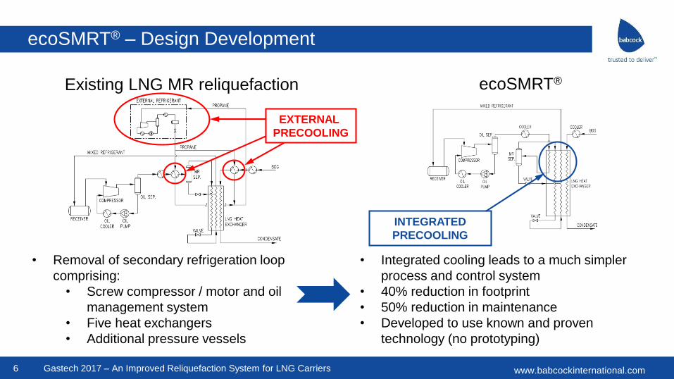
Existing LNG MR reliquefaction ecoSMRT®
• Removal of secondary refrigeration loop
comprising:
• Screw compressor / motor and oil
management system
• Five heat exchangers
• Additional pressure vessels
• Integrated cooling leads to a much simpler
process and control system
• 40% reduction in footprint
• 50% reduction in maintenance
• Developed to use known and proven
technology (no prototyping)
EXTERNAL
PRECOOLING
INTEGRATED
PRECOOLING
www.babcockinternational.com7 Gastech 2017 – An Improved Reliquefaction System for LNG Carriers
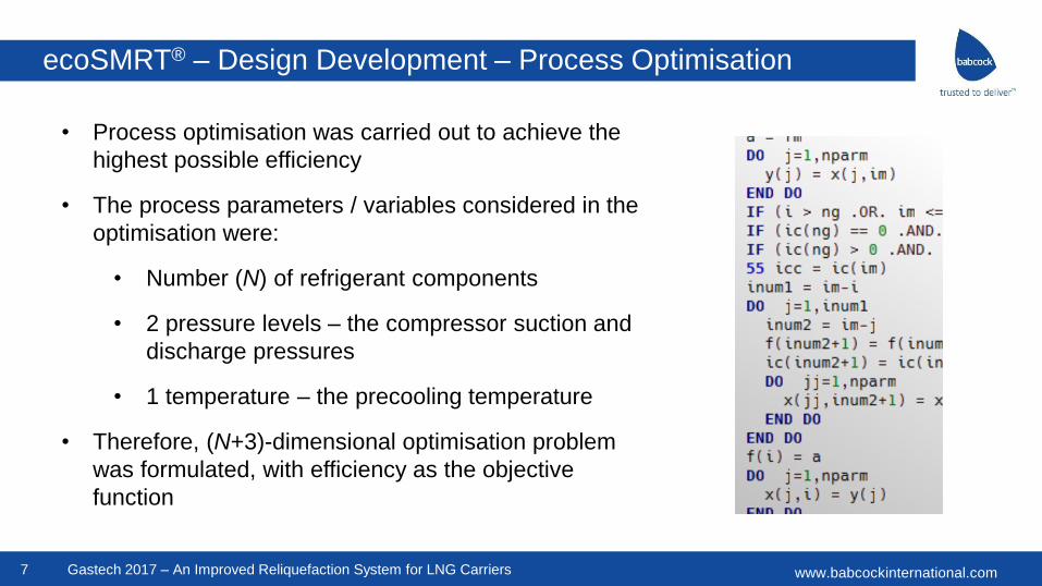
• Process optimisation was carried out to achieve the
highest possible efficiency
• The process parameters / variables considered in the
optimisation were:
• Number (N) of refrigerant components
• 2 pressure levels – the compressor suction and
discharge pressures
• 1 temperature – the precooling temperature
• Therefore, (N+3)-dimensional optimisation problem
was formulated, with efficiency as the objective
function
ecoSMRT® – Design Development – Process Optimisation
www.babcockinternational.com8 Gastech 2017 – An Improved Reliquefaction System for LNG Carriers
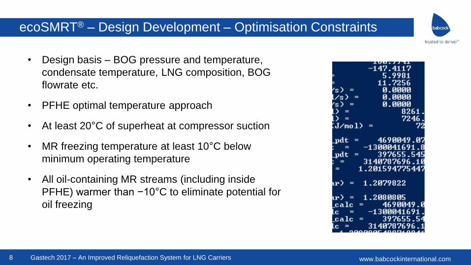
• Design basis – BOG pressure and temperature,
condensate temperature, LNG composition, BOG
flowrate etc.
• PFHE optimal temperature approach
• At least 20°C of superheat at compressor suction
• MR freezing temperature at least 10°C below
minimum operating temperature
• All oil-containing MR streams (including inside
PFHE) warmer than −10°C to eliminate potential for
oil freezing
ecoSMRT® – Design Development – Optimisation Constraints
www.babcockinternational.com9 Gastech 2017 – An Improved Reliquefaction System for LNG Carriers
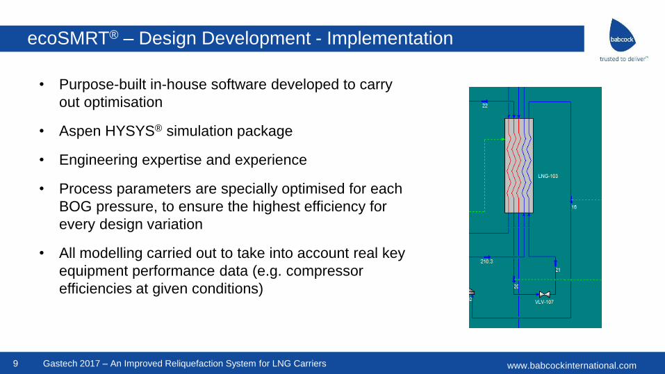
• Purpose-built in-house software developed to carry
out optimisation
• Aspen HYSYS® simulation package
• Engineering expertise and experience
• Process parameters are specially optimised for each
BOG pressure, to ensure the highest efficiency for
every design variation
• All modelling carried out to take into account real key
equipment performance data (e.g. compressor
efficiencies at given conditions)
ecoSMRT® – Design Development - Implementation
www.babcockinternational.com
ecoSMRT® – Process Visualisation
10 Gastech 2017 – An Improved Reliquefaction System for LNG Carriers
www.babcockinternational.com
ecoSMRT® – Process Visualisation
11 Gastech 2017 – An Improved Reliquefaction System for LNG Carriers
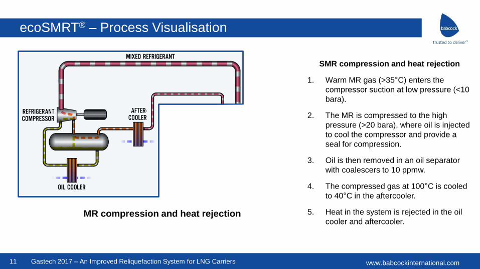
SMR compression and heat rejection
1. Warm MR gas (>35°C) enters the
compressor suction at low pressure (<10
bara).
2. The MR is compressed to the high
pressure (>20 bara), where oil is injected
to cool the compressor and provide a
seal for compression.
3. Oil is then removed in an oil separator
with coalescers to 10 ppmw.
4. The compressed gas at 100°C is cooled
to 40°C in the aftercooler.
5. Heat in the system is rejected in the oil
cooler and aftercooler.MR compression and heat rejection
www.babcockinternational.com
ecoSMRT® – Process Visualisation
12 Gastech 2017 – An Improved Reliquefaction System for LNG Carriers
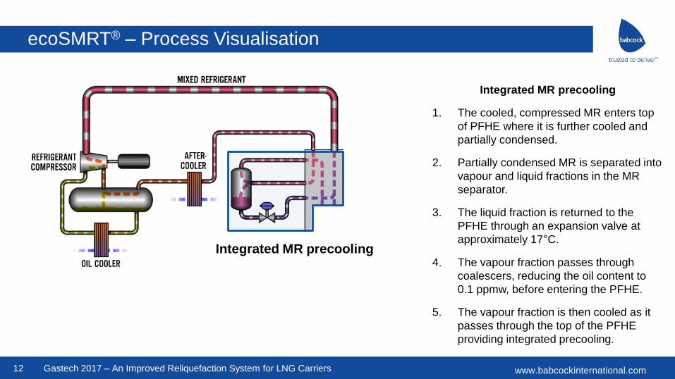
Integrated MR precooling
1. The cooled, compressed MR enters top
of PFHE where it is further cooled and
partially condensed.
2. Partially condensed MR is separated into
vapour and liquid fractions in the MR
separator.
3. The liquid fraction is returned to the
PFHE through an expansion valve at
approximately 17°C.
4. The vapour fraction passes through
coalescers, reducing the oil content to
0.1 ppmw, before entering the PFHE.
5. The vapour fraction is then cooled as it
passes through the top of the PFHE
providing integrated precooling.
Integrated MR precooling
www.babcockinternational.com
ecoSMRT® – Process Visualisation
13 Gastech 2017 – An Improved Reliquefaction System for LNG Carriers
LNG BOG
reliquefaction
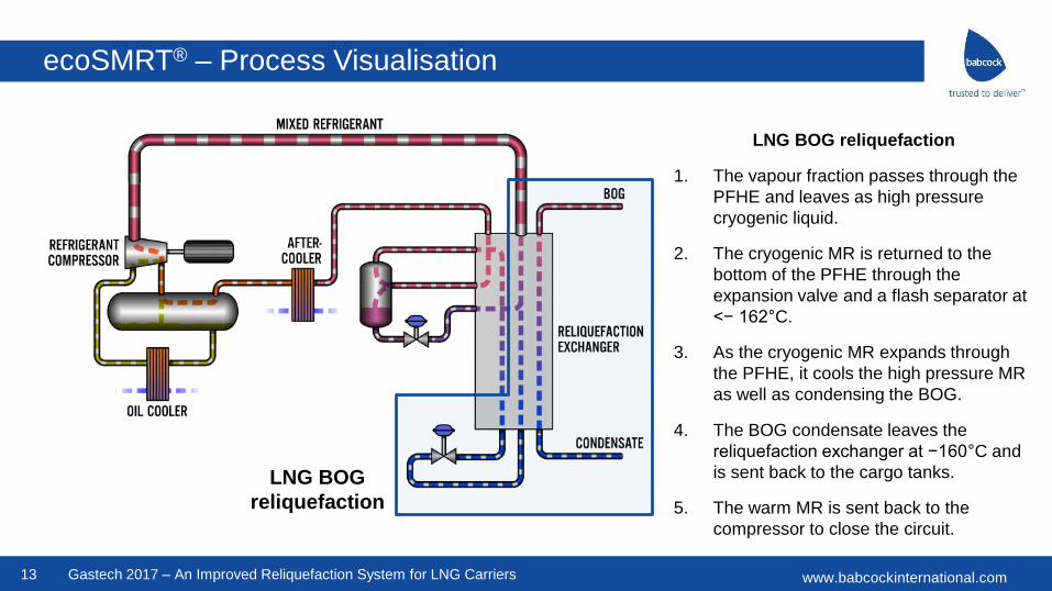
LNG BOG reliquefaction
1. The vapour fraction passes through the
PFHE and leaves as high pressure
cryogenic liquid.
2. The cryogenic MR is returned to the
bottom of the PFHE through the
expansion valve and a flash separator at
<− 162°C.
3. As the cryogenic MR expands through
the PFHE, it cools the high pressure MR
as well as condensing the BOG.
4. The BOG condensate leaves the
reliquefaction exchanger at −160°C and
is sent back to the cargo tanks.
5. The warm MR is sent back to the
compressor to close the circuit.
www.babcockinternational.com
ecoSMRT® – Oil Carryover Management
14 Gastech 2017 – An Improved Reliquefaction System for LNG Carriers
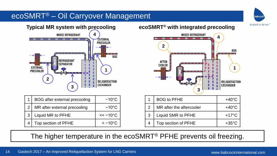
The higher temperature in the ecoSMRT® PFHE prevents oil freezing.
Typical MR system with precooling ecoSMRT® with integrated precooling
2
1
3
4
1
2
3
4
1 BOG after external precooling −10°C
2 MR after external precooling −10°C
3 Liquid MR to PFHE << −10°C
4 Top section of PFHE < −10°C
1 BOG to PFHE +40°C
2 MR after the aftercooler +40°C
3 Liquid SMR to PFHE +17°C
4 Top section of PFHE +35°C
www.babcockinternational.com
ecoSMRT® Plant Visualisation
15 Gastech 2017 – An Improved Reliquefaction System for LNG Carriers
www.babcockinternational.com
ecoSMRT® Plant Visualisation
16 Gastech 2017 – An Improved Reliquefaction System for LNG Carriers
www.babcockinternational.com
ecoSMRT® Standard Range
17 Gastech 2017 – An Improved Reliquefaction System for LNG Carriers
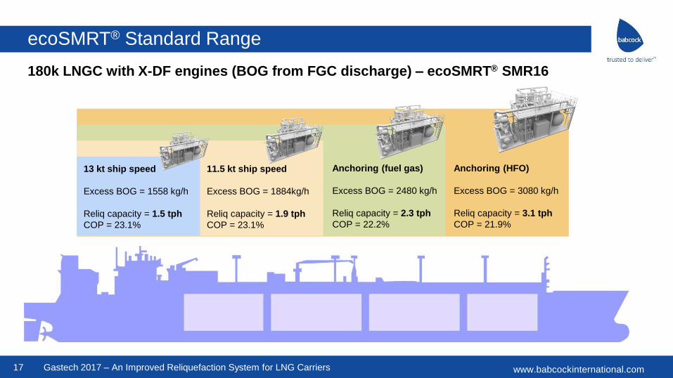
13 kt ship speed
Excess BOG = 1558 kg/h
Reliq capacity = 1.5 tph
COP = 23.1%
Anchoring (fuel gas)
Excess BOG = 2480 kg/h
Reliq capacity = 2.3 tph
COP = 22.2%
11.5 kt ship speed
Excess BOG = 1884kg/h
Reliq capacity = 1.9 tph
COP = 23.1%
Anchoring (HFO)
Excess BOG = 3080 kg/h
Reliq capacity = 3.1 tph
COP = 21.9%
180k LNGC with X-DF engines (BOG from FGC discharge) – ecoSMRT® SMR16
www.babcockinternational.com
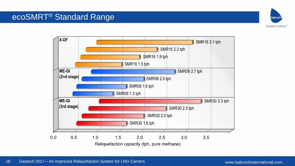
ecoSMRT® Standard Range
18 Gastech 2017 – An Improved Reliquefaction System for LNG Carriers
www.babcockinternational.com19 Gastech 2017 – An Improved Reliquefaction System for LNG Carriers
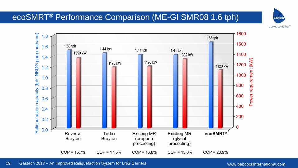
ecoSMRT® Performance Comparison (ME-GI SMR08 1.6 tph)

www.babcockinternational.com20 Gastech 2017 – An Improved Reliquefaction System for LNG Carriers
ecoSMRT® Efficiency Comparison (ME-GI SMR08 1.6 tph)
www.babcockinternational.com21 Gastech 2017 – An Improved Reliquefaction System for LNG Carriers
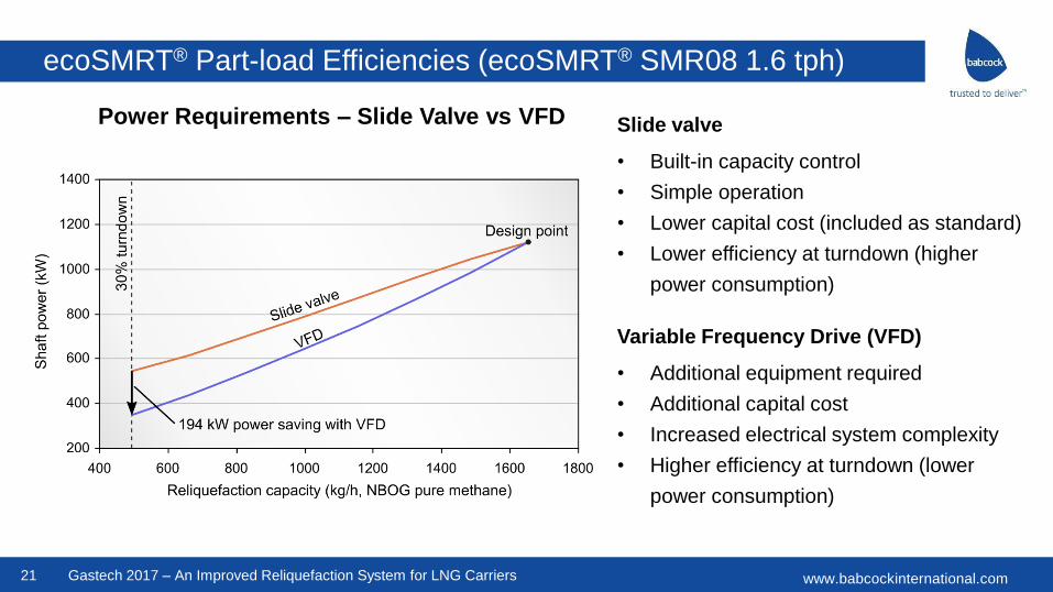
ecoSMRT® Part-load Efficiencies (ecoSMRT® SMR08 1.6 tph)
Power Requirements – Slide Valve vs VFD Slide valve
• Built-in capacity control
• Simple operation
• Lower capital cost (included as standard)
• Lower efficiency at turndown (higher
power consumption)
Variable Frequency Drive (VFD)
• Additional equipment required
• Additional capital cost
• Increased electrical system complexity
• Higher efficiency at turndown (lower
power consumption)
www.babcockinternational.com22
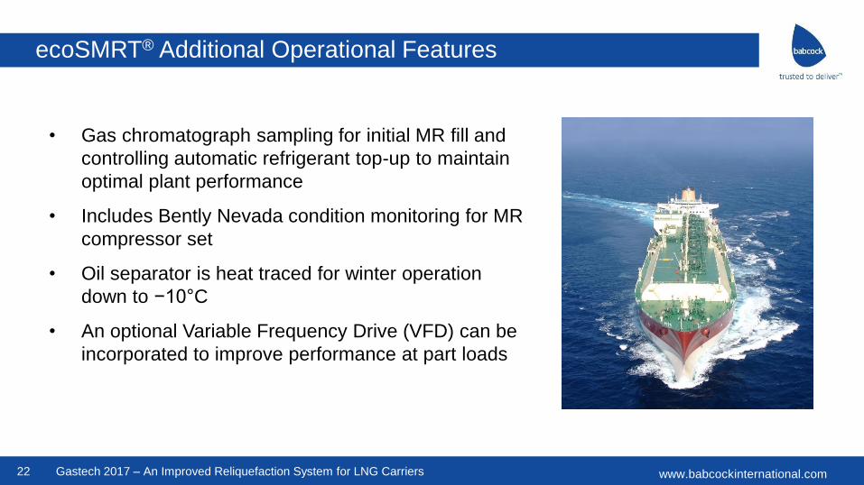
• Gas chromatograph sampling for initial MR fill and
controlling automatic refrigerant top-up to maintain
optimal plant performance
• Includes Bently Nevada condition monitoring for MR
compressor set
• Oil separator is heat traced for winter operation
down to −10°C
• An optional Variable Frequency Drive (VFD) can be
incorporated to improve performance at part loads
Gastech 2017 – An Improved Reliquefaction System for LNG Carriers
ecoSMRT® Additional Operational Features
www.babcockinternational.com23
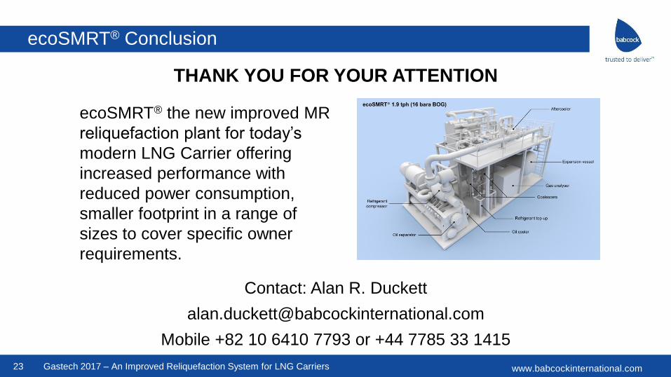
THANK YOU FOR YOUR ATTENTION
Contact: Alan R. Duckett
Mobile +82 10 6410 7793 or +44 7785 33 1415
Gastech 2017 – An Improved Reliquefaction System for LNG Carriers
ecoSMRT® the new improved MR
reliquefaction plant for today’s
modern LNG Carrier offering
increased performance with
reduced power consumption,
smaller footprint in a range of
sizes to cover specific owner
requirements.
ecoSMRT® Conclusion
www.babcockinternational.comGastech 2017 – An Improved Reliquefaction System for LNG Carriers


