14
Installaon and Operaon Instrucons ECU-Chill® 550 Ruggedized Environmental Control Unit OM00004 Rev. F
Installation and Operation Instructions
ECU-Chill® 550Ruggedized Environmental Control Unit
OM00004 Rev. F

Table of Contents
Installation Notes
Date of PurchaseDate of InstallationInstallerModel Number ECU-Chill 550 p/n FP00027Serial Number
SectionSystem Information Figure 1. ECU Front (External) View Figure 2. ECU Rear (Internal) View Cooling and Heating Performance Physical Specifications Table 1. Environmental SpecificationsSafety Power Lead Refrigerant NoiseInstallation Unpacking and Handling Tools and Information Needed for Installation Electrical Connection Figure 3. Power Cable Input Power Specifications Table 2. Input Power Cable Gasket and Enclosure Mounting Figure 4. ECU Mounting Details Internal Air Ducting Figure 5. ECU Air Flow External Drain Fitting Figure 6. External Drain Fitting Operation Table 3. ECU Operational StatesMaintenance Coil CleaningCustomer Service Warranty Warranty Repairs Technical Support Product RepairTechnical Drawings ECU Dimensions Center of Mass Panel Cutout Panel Gasket Power Connector
Page(s)1-2
112223333
4-74444445566667788
9-109
101010
11-121111121212
. . . . . . . . . . . . . . . . . . . . . . . . . . . . . . . . . . . . . . . . . . . . . . . . . . . . . . . . . . . . . . . . . . . . . . . . . . . . . . . . . . .
. . . . . . . . . . . . . . . . . . . . . . . . . . . . . . . . . . . . . . . . . . . . . . . . . . . . . . . . . . . . . . . . . . . . . . . . . .
. . . . . . . . . . . . . . . . . . . . . . . . . . . . . . . . . . . . . . . . . . . . . . . . . . . . . . . . . . . . . . . . . . . . . . . . . . . . . .
. . . . . . . . . . . . . . . . . . . . . . . . . . . . . . . . . . . . . . . . . . . . . . . . . . . . . . . . . . . . . . . . . . . . . . . . . . . . . . . . . . . . . . . . . . . . . . . . . . . . . . . . . . . . . . . . . . . . . . . . . . . . . . . . . . . . . . . . . . . . . . . . . . . . . . . . . . .
. . . . . . . . . . . . . . . . . . . . . . . . . . . . . . . . . . . . . . . . . . . . . . . . . . . . . . . . . . . . . . . . . . . . . . . . . . . . . . . . . . . . . . . . . . . . . . . . . . . . . . . . . .
. . . . . . . . . . . . . . . . . . . . . . . . . . . . . . . . . . . . . . . . . . . . . . . . . . . . . . . . . . . . . . . . . . . . . . . . . . . . . . . . . . .
. . . . . . . . . . . . . . . . . . . . . . . . . . . . . . . . . . . . . . . . . . . . . . . . . . . . . . . . . . . . . . . . . . . . . . . . . . . . . . . . . . . . . . . .
. . . . . . . . . . . . . . . . . . . . . . . . . . . . . . . . . . . . . . . . . . . . . . . . . . . . . . . . . . . . . . . . . . . . . . . . . . . . . . . . . .
. . . . . . . . . . . . . . . . . . . . . . . . . . . . . . . . . . . . . . . . . . . . . . . . . . . . . . . . . . . . . . . . . . . . . . . . . . . .
. . . . . . . . . . . . . . . . . . . . . . . . . . . . . . . . . . . . . . . . . . . . . . . . . . . . . . . . . . . . . . . . . . . . . . . . . . . . . . . . . . . . . . . . . . . . . . . . . . . . . . . . . . . . . . . . . . . . . . . . . . . . . . . . . . . . .
. . . . . . . . . . . . . . . . . . . . . . . . . . . . . . . . . . . . . . . . . . . . . . . . . . . . . . . . . . . . . . . . . . . . . . . . . . . . . . . . . . . . . . . . . .
. . . . . . . . . . . . . . . . . . . . . . . . . . . . . . . . . . . . . . . . . . . . . . . . . . . . . . . . . . . . . . . . . . . . . . . . . . . . . . . . . . . . . . . . . . .
. . . . . . . . . . . . . . . . . . . . . . . . . . . . . . . . . . . . . . . . . . . . . . . . . . . . . . . . . . . . . . . . . . . . . . . . . . . . . . . . . . . . . . . . . . . . . . . . . . . . . . . . . . . . . . . . . . . . . . . . . . . . . . . . . . . . . . . . . . . . . . . . . . . . . . .
. . . . . . . . . . . . . . . . . . . . . . . . . . . . . . . . . . . . . . . . . . . . . . . . . . . . . . . . . . . . . . . . . . . . . . . . . . . . . . . . . . . . . . . . . . . .
. . . . . . . . . . . . . . . . . . . . . . . . . . . . . . . . . . . . . . . . . . . . . . . . . . . . . . . . . . . . . . . . . . . . . . . . . . . . . . . . . . . . . . . . . . . . . . . . . .
. . . . . . . . . . . . . . . . . . . . . . . . . . . . . . . . . . . . . . . . . . . . . . . . . . . . . . . . . . . . . . . . . . . . . . . . . . . . . . . . . . . . . . . . . . . . . . .
. . . . . . . . . . . . . . . . . . . . . . . . . . . . . . . . . . . . . . . . . . . . . . . . . . . . . . . . . . . . . . . . . . . . . . . . . . . . . . . . . . . . . . . . . . . . . . . . . .
. . . . . . . . . . . . . . . . . . . . . . . . . . . . . . . . . . . . . . . . . . . . . .
OM00004 Rev. F

System Information
The ECU-Chill 550 (“ECU”) is designed to mount in a wall of an electronics enclosure and provide heating, cooling and dehumidification to maintain the internal temperature between 0°F and 125°F and relative humid-ity (RH) below 70%. The following photographs illustrate the front and rear of the unit.
Figure 1. ECU Front (External) View
Figure 2. ECU Rear (Internal) View
ECU-Chill 550 Installation & Operation Manual Page 1OM00004 Rev. F
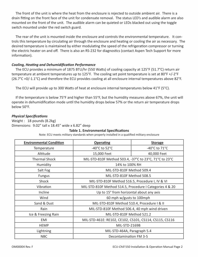
The front of the unit is where the heat from the enclosure is rejected to outside ambient air. There is a drain fitting on the front face of the unit for condensate removal. The status LED’s and audible alarm are also mounted on the front of the unit. The audible alarm can be quieted or LEDs blacked out using the toggle switch mounted under the red switch guard. The rear of the unit is mounted inside the enclosure and controls the environmental temperature. It con-trols this temperature by circulating air through the enclosure and heating or cooling the air as necessary. The desired temperature is maintained by either modulating the speed of the refrigeration compressor or turning the electric heater on and off. There is also an RS-232 for diagnostics (contact Aspen Tech Support for more information). Cooling, Heating and Dehumidification Performance The ECU provides a minimum of 1875 BTU/hr (550 Watts) of cooling capacity at 125°F (51.7°C) return air temperature at ambient temperatures up to 125°F. The cooling set point temperature is set at 80°F +/-2°F (26.7°C +0/-1.1°C) and therefore the ECU provides cooling at all enclosure internal temperatures above 82°F.
The ECU will provide up to 300 Watts of heat at enclosure internal temperatures below 41°F (5°C).
If the temperature is below 75°F and higher than 55°F, but the humidity measures above 67%, the unit will operate in dehumidification mode until the humidity drops below 57% or the return air temperature drops below 50°F.
Physical SpecificationsWeight : 18 pounds (8.2kg)Dimensions: 9.02” tall x 18.45” wide x 6.82” deep
Environmental Condition Operating StorageTemperature -40°C to 52°C -40°C to 71°C
Altitude 15,000 Feet 40,000 FeetThermal Shock MIL-STD-810F Method 503.4, -37°C to 23°C, 71°C to 23°C
Humidity 14% to 100% RHSalt Fog MIL-STD-810F Method 509.4Fungus MIL-STD-810F Method 508.5Shock MIL-STD-810F Method 516.5, Procedure I, IV & VI
Vibration MIL-STD-810F Method 514.5, Procedure I Categories 4 & 20Incline Up to 15° from horizontal about any axisWind 60 mph w/gusts to 100mph
Sand & Dust MIL-STD-810F Method 510.4, Procedure I & IIRain MIL-STD-810F Method 506.4, 40 mph wind driven
Ice & Freezing Rain MIL-STD-810F Method 521.2EMI MIL-STD-461E: RE102, CE102, CS101, CS114, CS115, CS116
HEMP MIL-STD-2169BLightning MIL-STD-464A, Paragraph 5.4
NBC Decontamination FM 3-5
Table 1. Environmental Specifications Note: ECU meets military standards when properly installed in a qualified military enclosure
ECU-Chill 550 Installation & Operation Manual Page 2OM00004 Rev. F

Safety
Power Lead supplied, unit does not have On/Off Switch ECU-Chill 550 in the standard configuration is provided with a power cable containing three leads: red (posi-tive), black (negative) and green (grounded to chassis). It is intended to operate on nominal 28 volt direct current power. The three leads are stripped and tinned to enable connection within an electronic enclosure by the customer. (Some units may be supplied with a pre-wired power connector if specified by the customer.) The ECU does not provide On/Off power switch capability. An On/Off power switch with an appropriate circuit breaker should be included in the enclosure for connection to the ECU-Chill 550.
CAUTION! Connecting the ECU to a power supply other than nominal 28 volts direct current (22 to 32 VDC) may cause severe damage to equipment and present a shock hazard!
Refrigerant R-134a ECU-Chill 550 contains Tetrafluoroethane (R-134a) as a refrigerant. R-134a is an approved long-term re-placement for CFC-based refrigerants and an approved ozone depleting substance (ODS) alternative. In the event that the ECU-Chill 550 is damaged, general work clothing, leather gloves, and eye protection should be worn to prevent exposure to refrigerants.
Precautions relating to the personnel hazards regarding contact with this substance should be outlined in training and technical manuals.
Disposal of R-134a and products containing R-134a must comply with federal, state, and local disposal or discharge laws.
CAUTION! Skin contact with refrigerant may cause frostbite!
CAUTION! R-134a is subject to U.S. Environmental Protection Agency Clean Air Act Regulations Section 608 in 40 CFR Part 82 regarding refrigerant recycling, therefore the refrigerant must be evacuated from the ECU prior to disposal of the assembly.
Noise ECU-Chill 550 produces a maximum noise level of 84 dBA at three (3) feet from the front of the unit. Instal-lation in the electronics enclosure should consider the proximity of the ECU-Chill face relative to personnel who operate the equipment.
CAUTION! Long-term exposure to high sound pressure levels may cause permanent hearing impairment!
ECU-Chill 550 Installation & Operation Manual Page 3OM00004 Rev. F

InstallationUnpacking and Handling ECU-Chill 550 in the standard configuration is delivered in a box containing:• One (1) ECU-Chill 550 (p/n FP00027) with condenser grill cover, and one (1) 48 inch power cord with flying leads attached • One (1) Installation Kit (p/n SA00221) including: • One (1) ECU-Chill 550 enclosure gasket • Twenty-four (24) mounting screws and nuts (10-32 x 1/2 inch) • One (1) Duckbill valve with 2 inch long silicone tube • Installation and Operation Manual Prior to installing and operating the ECU, read the Installation & Operating Manual along with any other safety/warning documentation. Consult with Aspen Systems, Inc. Technical Support for installation, operation or input power questions.
Tools Needed for Installation• Screwdriver or similar tool to attach ECU to enclosure installation flange• Additional tools as required to complete installation of the power cable
Electrical Connection The standard ECU-Chill 550 in the standard configuration is supplied with a 48 inch power cable with bare leads for connection to the power source. No on/off power switch is included in this configuration. Connec-tion to an appropriate power switch or circuit breaker is recommended. Customer specified power cable lengths and/or specific connectors may be ordered as optional equipment at the time of purchase. An exam-ple of the standard power cable is shown in Figure 3.
Figure 3. Power CableInput Power SpecificationsPower Supply Voltage: +28Vdc (+4.0 / -6.0VDC)Maximum Input Power: 525 WattsMaximum Input Current: 16.4 amperes The input current during operation varies depending on the operational state of the ECU. Standard Power Cord: 48” long, (3) 14 GA wires Table 2 details the input power conductor assignments.
Conductor Signal DescriptionRed +28 VDC Supply
Black -28 VDC ReturnGreen Chassis Chassis Ground
Table 2. Input Power Cable
ECU-Chill 550 Installation & Operation Manual Page 4OM00004 Rev. F

Gasket and Enclosure Mounting Installation of the ECU in a manner that meets the requirements of the cited military standards requires installation in an enclosure designed for use of the ECU. Care in designing the enclosure interface with the appropriate structural characteristics plus an ECU cut out with a flat surface and a bolt pattern as shown in the Panel Cutout drawing shown on Pg. 12. A gasket is required to provide a weather-tight seal between the ECU and the customer-supplied enclosure as shown in Figure 4. The gasket should be positioned between the enclosure interface opening and the ECU as shown in the figure. Improper installation of the gasket can lead to environmental contamination (rain, dust, sand) to the inside of the enclosure. An Installation Kit including a suitable gasket and mounting hard-ware is supplied with the ECU. Begin installation by removing the four screws and nuts attached to the corners of the ECU, holding the Con-denser grill (Face Plate) in place for shipping. Reserve the grill, screws and nuts to complete installation. The gasket supplied has a pressure sensitive adhesive on one surface. Feed the power cord through the middle of the gasket. Peel the paper covering from the adhesive and carefully slide the gasket (adhesive surface toward the ECU flange), over the ECU from the back (see Figure 2). Align the gasket holes to the mounting holes in the ECU flange and press the gasket to the ECU flange. Insert the ECU into the enclosure cut out. Using the #10 screws and nuts provided, (or customer supplied hardware, if longer or shorter screws are required) begin attaching the ECU to the enclosure. Note: the grill cover has clearance holes aligning with the mounting holes including clearance for screw heads in certain loca-tions. So, the ECU is mounted initially without the grill in place. Twenty-eight (28) screws shall be installed (24 in the Installation Kit plus the 4 used in shipping) into the mounting flange. Twelve screws can be attached prior to installing the grill plate. Lastly, replace the grill plate and attach it to the enclosure with the remain-ing sixteen screws and nuts. Once the screws are in place the gasket is compressed and an appropriate seal is obtained. The grill plate can be removed and replaced while in service, to facilitate the maintenance cleaning procee-dure, (described on Pg. 8).
CAUTION! This Environmental Control Unit must be installed in a sealed enclosure with a gasket between the enclosure face and the ECU mounting flange to prevent ingress of water and other contaminants. Failure to install in accordance with these instructions will void the product Warranty.
Figure 4. ECU Mounting Details
ECU-Chill 550 Installation & Operation Manual Page 5OM00004 Rev. F

Internal Air Ducting The ECU-Chill is provided with fans that circulate air within the enclosure through the evaporator. Ducting should be considered to direct cold air to internal components and return heated air to the ECU air intake. If proper baffling isn’t installed, the unit may not meet cooling capacity specifications. Figure 5 illustrates the air flow through the ECU. Improper air flow management can result in recirculation of cooled air back into the ECU-Chill inlet without benefit to the internal components, diminishing the cooling capacity of the ECU. The customer should evaluate the application to determine if internal ducting is required to achieve the desired air flow through the electronic heat load. Note that there are mounting locations for baffling on the top, bottom and sides of the ECU-Chill system (see the Technical Drawings on page 11 for more details).
Figure 5. ECU Air Flow
ECU-Chill 550 Installation & Operation Manual Page 6OM00004 Rev. F
Figure 6. External Drain Fitting
External Drain Fitting There is a drain fitting on the front face of the unit through which any condensate that is collected by the unit drains to the outside of the case. The fitting has a downward facing hose barb that acceppts a 1/4” ID, 3/8” OD silicon tube. A ~2” long piece of tubing is also provided in the Installation Kit. The customer may in-stall this short piece of tube onto the hose barb drain fitting with the duckbill valve on the other end as shown in Figure 6. The valve allows the condensate to drain from the ECU while proventing insects and dust from entering the ECU. If a longer tube is required to prevent water from dripping onto the equipment below, the customer may supply their own tube to the desired length and slip the duckbill valve onto the end.
Drain Fitting
Duckbill Fitting
Drain Tube

Operation The ECU is designed to operate when installed on a vertical surface (within +/-15 degrees on any axis). The ECU-Chill external fans must be at least 12 inches from any external obstructions for proper ventilation.
Upon completing the installation of the electronics in the enclosure and connection to the external power source, the system can be started. Ensure the enclosure is closed to the atmosphere and positioned on a hori-zontal surface. The ECU will start and operate automatically upon energizing the power cable.
The ECU operating states depend upon the temperature inside the enclosure. Operation within specified limits (between 4 and 125°F) is indicated by an illuminated green LED on the face of the ECU. If the enclosure internal temperature is outside the specified limits (below 4 or above 125°F) and the ECU is heating or cooling in an attempt to bring the operation within the specified limits, then the green LED will be illuminated (indicat-ing the ECU is working) and the red LED and alarm will also be on to indicate that the temperature inside the enclosure is outside the safe operating range. A problem with the ECU will result in a Fault Condition during which the ECU will not operate. In this case, the green LED will not be illuminated (indicating the ECU is not working) while the red LED and alarm will be on to indicate a problem. During Quiet and Blackout operating modes the switch on the face of the ECU can disable the LED lights, the Alarm, or both. The following de-scription provides an explanation of the operational states for the ECU:
Enclosure Temperature (°F/°C) Operation* Display ConditionBelow 4 (-16) Heating - On Green LED, Red LED and Alarm ON4 – 41 (-16 – 5) Heating - On Green LED - ON41 – 80 (7 – 26), RH < 67% Heating and Cooling Off Green LED - ON41 – 80 (7 – 26), RH > 67% Dehumidification - On Green LED - ON81 -125 (26 – 52) Cooling - On Green LED - ON Above 125 (51) Cooling - On Green LED, Red LED and Alarm ONRH > 70% for 60 minutes Dehumidification or Cooling - On Green LED, Flashing Red LED/AlarmFault ConditionsAll internal temperatures ECU non-functioning The tem-
perature measuring thermistors are either shorted or open, or the thermal switch on top of the com-pressor is open.
Red LED and Alarm ON
*The internal fans are on under all operating state conditions. External condenser fans cycle on during cooling or dehumidification operation only.
ECU-Chill 550 Installation & Operation Manual Page 7
Table 3. ECU Operational States
OM00004 Rev. F

MaintenanceDiagnosticsAn RS-232 diagnostics port is available, contact Aspen Tech Support for details.
Coil CleaningThis procedure is used to clean the ECU in the field.Equipment/Supplies Used
Equipment Name/Description QuantityCompressed air 1Phillips head screw driver, #2 1Air nozzle/air gun 1Safety goggles 1Ear protection 1
PROCEDURE - Level I Cleaning With an ECU mounted to an enclosure or transit case.
1. All work should be done while wearing safety glasses and ear protection.
2. Remove the ECU grill plate if possible (preferable but not necessary), by removing the (16) 10-32 phillips pan head screws (only the screws attached directly to the grill need to be removed)
3. Attach an air nozzle to a compressed air source regulated to between 50 and 100 psig.
4. Direct the air at the front face of the condenser coil about 2 to 4 inches from the face of the coil.
5. Air flow should be very close to perpendicular to the face of the coil. CAUTION! - High pressure air di- rected at an angle to the coil face could bend the leading edge of the fins which could cause damage to the coils and decrease overall ECU performance.
6. Sweep the air flow back and forth across the face of the coil to remove any excess contamination which may have built up during use.
7. Sand and dust will be pushed out the bank of fans on the bottom of the ECU front face.
8. Repeat steps 5 – 7 until you are satisfied with the level of cleaning.
9. Reattach the ECU grill by re-installing the (16) 10-32 Phillips pan head screws.
ECU-Chill 550 Installation & Operation Manual Page 8OM00004 Rev. F

Customer Service
WarrantyCOMMERCIAL PRODUCT WARRANTY Aspen System Inc. (hereinafter referred to as “Aspen”), warrants to the original purchaser that products sold shall be free from defects in material and workmanship for the warranty period not to exceed one year from the date of shipment. If buyer claims that a product violates such warranty, Aspen, upon notice promptly giv-en, will either examine the product at buyer’s site, or issue shipping instructions for return to Aspen at buyer’s expense, transportation charges prepaid.
Aspen’s sole obligation under its warranty shall be, at its option, to repair, replace or refund the price of any product thereof which is proved to violate such warranty. In no event, whether based on contract, indemnity, warranty, tort (including negligence), strict liability or otherwise, shall Aspen be liable to the buyer for special, indirect, incidental or consequential damages whatsoever including, without limitation, loss of profit or rev-enue.
The above warranty is buyer’s exclusive remedy and Aspen hereby expressly disclaims all other warranties, express or implied, including the implied warranty of merchantability and the implied warranty of fitness for a particular purpose. The foregoing shall constitute the sole remedy of the buyer and the sole liability of Aspen.
This Limited Warranty shall not apply to any product or component thereof which has been repaired or al-tered outside of Aspen’s factory in any manner so as, in Aspen’s sole judgment, to affect its serviceability, or to any product that has been subject to alteration, accident, misuse, abuse, neglect or normal wear. The Limited Warranty shall not apply to products which have been assembled or installed or used in a manner contrary to Aspen’s printed instructions, or due to failure to follow Aspen printed instructions for operation and main-tenance. This product is designed and intended to be installed and operated in an enclosure that is sealed from the ambient environment. Any technical assistance provided by Aspen’s personnel or representatives in system design is construed to be a proposal and not a recommendation. The responsibility for determining feasibility rests with the user and should be subject to test. Only the terms expressed in this Limited Warranty shall apply and no distributor, corporation or individual is authorized to amend, modify or extend this warranty in any way on resale.
ECU-Chill 550 Installation & Operation Manual Page 9OM00004 Rev. F

Warranty Repairs Any product returned and found to be under warranty will be repaired or replaced at the discretion of Aspen Systems, Inc. Unauthorized opening of the ECU (enclosure) will result in automatic void of the warranty.
Technical Support Technical Support is available from Aspen Systems, Inc. from 8:00 AM to 5:00 PM (EST) Monday through Friday (508) 281-5322. Technical support can also be requested on-line at www.aspensystems.com/contact To expedite assistance for problems, be able to provide the following information:• Your name, Phone number, Company, Division and City• Product with which you are having trouble• Serial Number and Revision (located on the side of the ECU)• Detailed description of your problem
Product Repair Depending on the circumstances of the problem, it may be deemed necessary to return the products to Aspen Systems, Inc. for repair. In order to return the product for repair, the following steps are necessary:
1. Obtain a Return Material Authorization Number (RMA#) from Aspen Systems, Inc from the website at www.aspensystems.com.• Open the website, and at the top of the page• Click on Contact• Click on Technical Support• Fill out the form completely and submit it to Aspen Systems, Inc.
2. Provide a Product Defect Report - When you are returning a product for repair, it is very important to include a written report that details the nature of the problem in order to expedite the repair. Ensure the following information is included:• RMA Number• Product• Serial Number• Contact information• Phone Number• Description of the Problem/Defect using detailed information, including environmental information, failure mode etc.
3. Shipping - Any product returned to Aspen Systems, Inc shall be prepaid by the customer and should be in its original shipping carton if possible. Please mark the shipping label with the RMA number and return it to:
Aspen Systems, Inc.ATT: RMA# (put RMA number here)24 St. Martin Dr. Marlborough, MA 01752 USA
ECU-Chill 550 Installation & Operation Manual Page 10OM00004 Rev. F

Technical Drawings
ECU-Chill 550 Installation & Operation Manual Page 11OM00004 Rev. F

ECU-Chill 550 Installation & Operation Manual Page 12OM00004 Rev. F


