ECU FUNCTION DEVELOPMENT OFFLINE CALIBRATION AND VALIDATION As a manufacturer of high-tech engines, Audi relies on the in-house development of central engine ECU functions. Depending on the application and project specifications in individual cases, the respective functions are developed either in Ascet or in Matlab / Simulink. Prototyping in the vehicle or on the test bench is handled by systems supplied by dSpace and Etas. For calibrating production engine ECUs, Audi deploys the Inca measuring and calibration sys- tem. The authors from Audi, Etas and Matis show how this tool enabled the calibration and validation of function models for the engine management on the PC in the Simulink environment. As regards the calibration and validation of new controls, Audi’s objective is to deploy Inca as early as during function development with Matlab/Simulink. This approach has several inherent benefits. On the one hand, users are able to work in their familiar calibration environment. On the other hand, the exchange of mea- surement and calibration data between individual development steps and the final production calibration is seamless and entirely transition-free. This not only simplifies the precalibration of ECU func- tions but also facilitates – in one and the same Inca environment – a direct compar- ison of the behavior of functions in the ECU, the prototype, and the function model. INTERFACING INCA AND MATLAB / SIMULINK With the intent to enable the calibration and validation of functions directly during offline simulations on the PC with Inca, Etas was asked to integrate Inca directly into Audi’s Matlab/Simulink environ- ment, 1 . The resulting integration pro- vides function developers with the numer- ous special tools incorporated in Inca – such as virtual measuring instruments, calibration editors, analytical tools for measurement and calibration data, plus its various triggering options – all of which are absent from the generic Matlab/Simulink environment. 36 INDUSTRY DEVELOPMENT PROCESSES
Transcript
ECU FUNCTION DEVELOPMENT OFFLINE CALIBRATION AND VALIDATIONAs a manufacturer of high-tech engines, Audi relies on the in-house development of central engine ECU functions.
Depending on the application and project specifications in individual cases, the respective functions are developed
either in Ascet or in Matlab / Simulink. Prototyping in the vehicle or on the test bench is handled by systems supplied
by dSpace and Etas. For calibrating production engine ECUs, Audi deploys the Inca measuring and calibration sys-
tem. The authors from Audi, Etas and Matis show how this tool enabled the calibration and validation of function
models for the engine management on the PC in the Simulink environment.
As regards the calibration and validation of new controls, Audi’s objective is to deploy Inca as early as during function development with Matlab/Simulink. This approach has several inherent benefits. On the one hand, users are able to work in their familiar calibration environment. On the other hand, the exchange of mea- surement and calibration data between individual development steps and the final production calibration is seamless and entirely transition-free. This not only
simplifies the precalibra tion of ECU func-tions but also facilitates – in one and the same Inca environment – a direct compar-ison of the behavior of functions in the ECU, the prototype, and the function model.
INTERFACING INCA AND MATLAB / SIMULINK
With the intent to enable the calibration and validation of functions directly during
offline simulations on the PC with Inca, Etas was asked to integrate Inca directly into Audi’s Matlab/Simulink environ-ment, 1. The resulting integration pro-vides function developers with the numer-ous special tools incorporated in Inca – such as virtual measuring instruments, calibration editors, analytical tools for measurement and calibration data, plus its various triggering options – all of which are absent from the generic Matlab/Simulink environment.
36
INDUSTRY DEVELOPMENT PROCESSES
MODELING GUIDELINES
In order to implement the most seamless connection possible between calibration tool and simulation environment, adher-ence to Audi’s specific modeling guide-lines was required. Audi uses standard-ized MBFS modules (Model Based Func-tion Specification, an ASAM standard) to assemble ECU function models inde-pendently of development tools. While this ASAM-conformant modeling tech-
nique fosters a common understanding among developers, it also promotes the exchange of complex functions among project participants. At Audi, the desig-nations of ECU parameters and signals are centrally managed by means of an Automotive Data Dictionary (ADD). In conjunction with the MBFS standard, the ADD name register unambiguously defines measurement signals, character-istic values, program maps, and axes. Thanks to these prerequisites, parameter
and signal values can be automatically extracted from the Simulink model and transferred to Inca.
INCA-SIP
The integration of Inca was implemented in the form of a Simulink toolbox. Installing the Inca-SIP toolbox equips Matlab/Simu link with additional menu functions that are then used to establish the connection between Inca and the
DIPL.-ING. (FH) JOHANN GABLERworks in the Development Area for
Rapid Prototyping Tools in the Software and Function Development
Section for Powertrain at Audi AG in Ingolstadt (Germany).
AUTHORS
DIPL.-ING. DANIEL KÖHLERis Project Manager and Function
Developer in the Software and Function Development Section for
Powertrain at Audi AG in Ingolstadt (Germany).
DIPL.-ING. THOMAS HEINZLERis Development Engineer at Matis
Deutschland GmbH in Munich (Germany). He is a dedicated
Development Partner of Audi AG.
DR. ULRICH LAUFFis Technical Editor-in-Chief for
the Measuring, Calibration and ECU Diagnostics Application Areas
in the Marketing Department of Etas GmbH in Stuttgart (Germany).
3705I2010 Volume 5
Simulink model, 2. As part of the ini-tialization of a simulation, Inca-SIP gen-erates – based on the analysis of the Simulink model – a descrip tion of the calibration data in the ASAM A2L for-mat, a hex file, and an experiment con-figuration in Inca. In the event of a new initialization of a simulation subsequent to a functional modification of the model, the Inca objects are automati-cally updated. With the model running
Simu link, Inca permits the starting and stopping of measurements, and their recording in the form of MDF files.
Inca-SIP supports two simulation modes: The Fast Emulation Mode runs the simulation at maximum speed. In the Real-Time Emulation Mode, the in-vehicle timing behavior of a given function is all but identical with that of the simulation. Using this mode, the model can be calibrat ed with the same dynamics as in-
vehicle. The data exchange with Inca is handled by an XCP interface provided by Inca-SIP. This interface makes it possible to run the simulation, independently of Inca, on a sufficiently powerful computer – a capability that also supports the simula-tion of ex tremely complex models on cen-tral servers.
Inca-SIP enables Inca to automatically record measurement data generated in Simulink. This measurement data can be used as a reference for both the subse-quent development steps and in-vehicle road testing. Conversely, the simulation can be stimulated with captured in-vehi-cle Inca measurement data and the be -havior of a specific function analyzed in the Simulink model. This practice facili-tates the diagnosis of functional failures of prototype or production functions in the Simulink model.
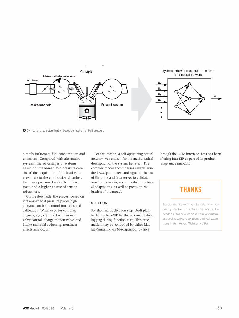
As a first project at Audi, Inca-SIP is de -ployed for the offline calibration of the cylinder charge determination based on intake-manifold pressure 3. As the accu-rate calculation of the fresh air mass within the combustion chamber forms the basis for precise fuel metering, it
1 Integration of Inca and Matlab/Simulink
2 Inca-SIP throughout the function development process
INDUSTRY DEVELOPMENT PROCESSES
38
directly influences fuel consumption and emissions. Compared with alternative systems, the advantages of systems based on intake-manifold pressure con-sist of the acquisition of the load value proximate to the combustion chamber, the lower pressure loss in the intake tract, and a higher degree of sensor robustness.
On the downside, the process based on intake-manifold pressure places high demands on both control functions and calibration. When used for complex engines, e.g., equipped with variable valve control, charge-motion valve, and intake-manifold switching, nonlinear effects may occur.
For this reason, a self-optimizing neural network was chosen for the mathematical description of the system behavior. The complex model encompasses several hun-dred ECU parameters and signals. The use of Simulink and Inca serves to validate function behavior, accommodate function- al adaptations, as well as precision cali-bration of the model.
OUTLOOK
For the next application step, Audi plans to deploy Inca-SIP for the automated data logging during function tests. This auto-mation may be controlled by either Mat-lab/Simulink via M-scripting or by Inca
through the COM interface. Etas has been offering Inca-SIP as part of its product range since mid-2010.
3 Cylinder charge determination based on intake-manifold pressure