61
ECUMASTER PMU-16/PMU-16DL Preliminary Manual (10.07.2017, rev. 1.01) Page 1
| Date post: | 26-May-2018 |
| Category: |
Documents |
| Upload: | trinhquynh |
| View: | 233 times |
| Download: | 0 times |

ECUMASTER PMU-16/PMU-16DL Preliminary Manual
(10.07.2017, rev. 1.01)
Page 1

ATTENTION!
• The ECUMASTER PMU is designed for motorsport applicationsonly and cannot be used on public roads!
• The installation of this device should be performed only bytrained specialists. Installation by untrained individuals maycause damage to both the device and the vehicle!
• Incorrect configuration of the ECUMASTER PMU can causeserious damage to vehicle components!
• Never modify the device’s settings while the vehicle is moving asit may cause an accident!
• ECUMASTER assumes no responsibility for damage caused byincorrect installation and/or configuration of the device!
• To ensure proper use of ECUMASTER PMU and to prevent risk ofdamage to your vehicle, you must read these instructions andunderstand them thoroughly before attempting to install this unit.
• Never short-circuit the wires of the vehicle's wiring loom or theoutputs of the ECUMASTER PMU!
• All modifications to the vehicle's wiring loom must be performedwith the negative terminal of the battery disconnected.
• It is critical that all connections in the wiring loom are properlyinsulated!
• The device must be disconnected before performing any weldingon the vehicle!
Page 2

Table Of ContentsECUMASTER PMU ............................................................................................................... 5
Technical ............................................................................................................................ 5Specification ....................................................................................................................... 6
SOFTWARE INSTALLATION ................................................................................................ 8Compatibility ...................................................................................................................... 8Downloading the PMU software ........................................................................................ 8Installing PMU software ..................................................................................................... 8
CONNECTING PMU TO PC ................................................................................................ 11CAN – USB interface ....................................................................................................... 11ECUMASTER USBtoCAN interface ................................................................................ 11ECUMASTER USBtoCAN pinout .................................................................................... 12Connecting USB interface, wiring schematics ................................................................. 13PMU status ...................................................................................................................... 13CAN protocol, CAN topology ........................................................................................... 14
USING PMU SOFTWARE ................................................................................................... 15Launching PMU software ................................................................................................. 15Using PMU software ........................................................................................................ 15PMU Client workflow ........................................................................................................ 17
ELEMENT TYPES ............................................................................................................... 19Analog Input ..................................................................................................................... 19Power Output ................................................................................................................... 19CANbus Message Object (Mob) ...................................................................................... 19CANbus Input ................................................................................................................... 19CANbus Keyboard ........................................................................................................... 19Switch .............................................................................................................................. 19Number ............................................................................................................................ 20Function ........................................................................................................................... 20Wipers Module ................................................................................................................. 20Blinkers Module ............................................................................................................... 20CANbus Export ................................................................................................................ 20
MANAGING ELEMENTS .................................................................................................... 20Saving elements .............................................................................................................. 20Loading saved elements .................................................................................................. 20
FUNCTIONS ........................................................................................................................ 21Main Principle .................................................................................................................. 21Operations ...................................................................................................................... 21Function examples .......................................................................................................... 23
CHANNEL LOGGING .......................................................................................................... 25Graph Log ........................................................................................................................ 25Logging Frequency .......................................................................................................... 26Custom Log ...................................................................................................................... 26
PMU PINOUT ....................................................................................................................... 27Output Pins ...................................................................................................................... 28Input Pins ......................................................................................................................... 28
PMU TEMPERATURE, PLACEMENT AND LOAD BALANCING ..................................... 28PMU Placement ............................................................................................................... 28PMU Temperature ............................................................................................................ 28Output Load Balancing .................................................................................................... 29
Page 3
Output Pin signaling and status ....................................................................................... 30WIRING ................................................................................................................................ 31
Basic diagram .................................................................................................................. 31Wire Size .......................................................................................................................... 32Load examples for popular devices ................................................................................. 32
ANALOG INPUT WIRING ................................................................................................... 33Wiring schematics ............................................................................................................ 33Analog Sensor ................................................................................................................. 36
OUTPUT DEVICES .............................................................................................................. 37Power Output ................................................................................................................... 37Simple Power Output Setup ............................................................................................ 38Wipers .............................................................................................................................. 40Blinkers ............................................................................................................................ 41CANbus Keyboard ........................................................................................................... 42Exporting Keyboard state ................................................................................................ 43Using CANbus Keyboard to signal status ........................................................................ 43Using output pins in parallel ............................................................................................. 45
INERTIA SWITCH ................................................................................................................ 45Inertia Switch ................................................................................................................... 45
MASTER RETRY CHANNEL .............................................................................................. 46PWM (PULSE WIDTH MODULATION) ............................................................................... 46
Soft Start .......................................................................................................................... 47Duty Cycle ........................................................................................................................ 47Using flyback diode .......................................................................................................... 48
USING MULTIPLE PMUs .................................................................................................... 49Basic Diagram .................................................................................................................. 49Communication ................................................................................................................ 49Using PMU Client with multiple PMUs ............................................................................. 50
CAN STREAM ..................................................................................................................... 51CANbus Export ................................................................................................................ 51CANbus Input ................................................................................................................... 51Importing .CANX File ....................................................................................................... 52Standard CAN Stream ..................................................................................................... 54
DOCUMENT REVISION HISTORY ..................................................................................... 58
Page 4

ECUMASTER PMU
ECUMASTER PMU is an inteligent power management unit designed to replace the old, traditionaland often unreliable fuses and relays. PMU is not only an electronic switch, but a device that canperform all kinds of advanced operations, validate logical conditions, manage abnormal situations,as well as log its parameters for you to have an oversight. PMU allows you to power up externaldevices such as fan, blinkers, wipers, oil pump etc. and create advanced strategies for thosedevices using logic with failsafes, condition checking and many more functions. It cancommunicate and work in tandem with other ECUMASTER CAN devices. It is equipped with overand under current protection, surge protection, 3D gyroscope, accelerometer, LED Status lights,Soft Start, Pulse Width Modulation with Duty Cycle control and more.
Technical
Page 5

Specification
GENERAL
Temperature Range ACEQ100 GRADE1 (-40 to 120C)
CPU 32 bits automotive, 90MIPS
Reverse polarity protection
Yes, internal
Operating voltage 6-22V immunity to transients according to ISO 7637
Enclosure IP65, bespoke CNC machined aluminium
Size and weight 131x112x32.5mm, 345g
Connectors 1 x 39 Automotive connector1 x M6 stud for battery connection
PC communication CAN (Peak CAN, ECUMASTER USBCAN, Kvaser)
Multiple PMUs Up to 5 PMUs can work in tandem
OUTPUTS
High Current Outputs 10 x 25A(cont.), 6 x 15A(cont.) with Overcurrent and overheating protection. Outputs may be paired to increase continuous current capability.Current and voltages measured for each output
Total current output 150A continuous
Output current control step
100mA
PWM Yes, available for each 25A output Programmable variable Duty Cycle control for each outputSeparate frequency setting ranging from 4Hz to 400Hz for each output
Soft Start Yes, available for each 25A output
Wipers output dedicated output with wiper braking feature
+5V monitored 5V, 500mA output for powering external sensors
INPUTS
Analog Inputs 16 inputs, 10 Bit resolution, 0-5V (protected), with software selectable 10K Ohm pullup and pulldowns
CAN Keypads 2 x Ecumaster keypads (4, 6, 8, 12 keys), LifeRacing PDU Keypad
OTHER
Output state indication 16 bicolor LEDs
Accelerometer/Gyrosco 3D accelerometer with 3D gyroscope for logging and crash
Page 6

pe detection
Real Time Clock Yes, super capacitor for backup power (up to 3 days)
CAN BUS
CAN interface 2 x CAN2.0 A/B
CAN standard 2.0A/B 125, 250, 500, 1000 Kbps
Input/Output Stream User defined with bit maskingUp to 48 input messages
LOGGING (PMU16DL only)
Logging Memory 256 Mbytes
Logging Speed Variable, defined per channel, up to 500Hz
PC LOGGING
Logging Speed Variable, defined per channel, up to 500Hz
FUNCTIONS
Logical Operations isTrue, isFalse, =, !=, <, <=, >, >=, AND, OR, XOR, Flash, Pulse,Toggle, Set/Reset Latch
Number of functions 100
Number of operations 250
Update frequency 500Hz
Special functions Wipers, Blinkers
Page 7

SOFTWARE INSTALLATION
Compatibility
PMU Software is compatible with Windows XP/Vista/7/8/8.1/10.
Downloading the PMU software
To configure PMU device a PMU Client must be used (both PMU16 and PMU16DL use the sameclient). To download PMU software please head to www.ecumaster.com/pmu page.
Installing PMU software
To install PMU software, double click the downloaded “PMUSetup_X_XXX_X.exe”.
Click Next to proceed.
Page 8

Choose which folder to install the PMU Client to.
Choose wheter you want a desktop icon or not.
Page 9

This is the summary of your installation, if both the folder and icon choice are correct, press Installto proceed. If not, you can go back to make a quick correction.
After the installation is finished, you can choose to launch PMU Client right away.
Page 10

CONNECTING PMU TO PC
CAN – USB interface
To properly connect PMU to PC using USB 2.0 a special interface must be used. PMU Clientsupports three interfaces:
• ECUMASTER USBtoCAN interface (can be bought directly from www.ecumaster.com)• PEAK Systems PCAN-USB • Kvaser USBcan
Each interface must have its drivers installed. Interface must be bought separately.
ECUMASTER USBtoCAN interface
To use ECUMASTER USBtoCAN interface, user must be equipped in following items:• USB A to USB B adapter to connect the interface to PC• DB-9 Cable to connect interface to PMU• ECUMASTER USBtoCAN interface drivers, available at:
http://www.ecumaster.com/products/usb-to-can/
To install drivers run EUSBtoCAN_Driver_v1.0.exe and follow installation instructions.Basic cable connection should look like this.
ECUMASTER USBtoCAN also has LED signaling ability:
Color Description
Green Continuous Device turned on
Green Flashing Device turned on and connected to PC
Green and Orange Flashing
Data transfer in progress
Orange Continuous Device turned on, currently in bootloader
Orange Flashing Device turned on, firmware update in progress
Red Continuous Temporary CAN communication error
Red Flashing Permanent CAN communication error
Page 11
USBtoCAN connection

ECUMASTER USBtoCAN is equipped with 120Ohm CAN terminator which can be switched on oroff by user. Picture below shows terminator switch location:
ECUMASTER USBtoCAN pinout
Page 12

Connecting USB interface, wiring schematics
To connect PMU to PC, CAN1 CANbus must be used. This is the CAN provided for us for PCcommunication. To wire the USB - CAN interface, CAN1H and CAN1L pins (See PMU Pinoutsection) must be used. Twisted pairing is also recommended. CANbus must also be terminated atboth ends of the bus. ECUMASTER USBtoCAN is equipped with one terminator that can beswitched on or off (See ECUMASTER USBtoCAN interface section).If the Interface is connected, PMU must be supplied with power, both on the +12SW Pin (See PMUPinout section) and the M6 stud.
Here is a simple diagram of USB connection, please note that it assumes that the secondterminator is applied by the USBtoCAN interface:
PMU status
PMU device is fitted with LED that signals status of the PMU device. Picture showing the LED location:
There are 6 possible states of PMU LED:
Color Status
Green Continuous Device is active
Orange Continuous Device is active and connected to PC
Green Flashing Slowly
Device is waiting for Firmware Upgrade
Page 13
PMU - PC communication
ATTENTION !Ground wire connection between USBtoCAN and PMU-16 can be DANGEROUS!
Ground connection is only allowed if devices before connecting have the same ground potential. Potential difference can be checked by using voltometer between corresponding grounds.

Orange Flashing Slowly
Device is performing Firmware Upgrade and is connected to PMUClient
Orange Flashing Fast Device is performing Make Permanent operation
Red Continuous Device Error - please contact the distributor or manufacturer directly
CAN protocol, CAN topology
CAN topology looks like this:
For 1Mbit/s connection (CAN 1), following rules must be abided:• Maximum unterminated cable length from device to CANbus is 30 cm• Maximum bus length is 40m.• Maximum of 30 nodes• 120 Ohm terminators must be applied at both ends of CAN bus.• Twisted pairing is required.
For 500kbit/s connection (CAN 2) following rules must be abided:• Maximum unterminated cable length from device to CANbus is 30 cm• Maximum bus length is 100m.• Maximum of 30 nodes• 120 Ohm terminators must be applied at both ends of CAN bus. PMU is equipped with
CAN2 terminator which can be turned on or off via PMU Client (Tree View → CAN Setup)• Twisted pairing is required.
Page 14
CAN Topology

USING PMU SOFTWARE
Launching PMU software
To run PMU software either doubleclick the icon on desktop, or use start menu to find it.
Using PMU software
When PMU Client is launched for the first time, user will be asked to enter the name of his device.All projects will then be saved to the directory corresponding to devices name.
After entering the Client, main window will appear:
Using the Client is pretty straightforward. The Project Tree window is the most significant one. You can use it to set up analog inputs, configure power outputs, create functions etc.To create elements, either use the toolbar with icons located on Project Tree window, use Alt + A Keyboard shortcut or click Add button, then select the type of element you want to create.
Page 15
Default Dekstop/Main Window with highlited Project Tree window
New device name
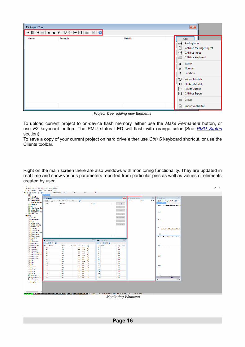
To upload current project to on-device flash memory, either use the Make Permanent button, oruse F2 keyboard button. The PMU status LED will flash with orange color (See PMU Statussection).To save a copy of your current project on hard drive either use Ctrl+S keyboard shortcut, or use theClients toolbar.
Right on the main screen there are also windows with monitoring functionality. They are updated inreal time and show various parameters reported from particular pins as well as values of elementscreated by user.
Page 16
Project Tree, adding new Elements
Monitoring Windows

On the left, there is a Tree View double clicking any item on it, will bring up it's window to current desktop.
PMU Client workflow
PMU Client workflow is really simple. You can monitor parameters of your channels, makeadjustments, follow the graph log to understand channels behavior, you can create elements, thenuse those to control other elements or channels.Elements and channels in this case can be anything, Power Output, Analog Input, Function, Switchetc.Let's take a look at two more in-depth use cases.
Page 17
Tree View

These are just two examples of how PMU Client can be used, but the possibilities are endless.
Page 18

ELEMENT TYPES
Analog Input
Analog inputs are input devices connected directly to the PMU. Below is the list of analog inputs supported by PMU.
• Switch - Active High• Switch - Active Low• Rotary Switch• Analog Sensor
Head to Wiring section to see wiring diagrams for each type of analog input.
Power Output
Power Outputs are devices powered by PMU which are connected to particular output pins.Power Output examples:
• Fuel Pump• Fan• Oil Pump
Every Power Output has over current, under current (both user configurable) and overheatprotection. They can be either turned on by default, controlled by function or triggered by anotherelement such as Analog Input
CANbus Message Object (Mob)
CANbus Message Objects are interfaces needed for data gathering from CAN Stream. They reada particular number of frames (user defined, up to 8) starting from particular ID (also user defined)from chosen CANbus. Maximum of 8 CANbus Message Objects can be created for each CANbus.They also have special timeout flag which can be used to set up a different strategy if a connectionfrom another CAN device times out.
CANbus Input
CANbus Inputs use CANbus Message Objects to extract data from chosen frame. They are able toread a user defined number of bits starting from user defined position, then apply offsets, divisionor multiplication to the extracted data.
CANbus Keyboard
CANbus Keyboard is an element that provides communication with Keyboard. It is used to defineand handle Keyboard buttons, set their color, type etc.
Switch
You can use two types of switches:• Latching Switch – switches between user defined number of states.• Press Hold Switch – short press switches between high and low state, holding it triggers
third state.
Page 19

Number
Number is simply an integer. It can be either a typed in constant or value of chosen channel.Number is mostly used for comparison or to control Duty Cycle in Pulse Width Modulation (SeePWM section).
Function
Function is one of the most important elements. It can be used to create a set of rules, conditionsto Power on an output device. Function always evaluates to either 0 or 1. If the function is used ascontrol channel for a Power Output, the Power Output will be turned on if function returns 1 andturned off if function returns 0. Functions will be explained in depth later on in Functions section.
Wipers Module
Wipers module is a separate module to control the Wipers. It consists of two Power Outputs forslow and fast wiper speed and an Analog Input for Park Switch. To use park functionality, OutputPin O8 is provided to use for slow wiper speed. To see the wiring instructions, head to Wiring partof the manual.
Blinkers Module
Blinkers module is a bit like Wipers Module, it is a separate element which controls the blinkers. Itconsists of two Power Outputs for left and right blinkers and needs three inputs (ie. CANbusKeyboard) to control the Left Blinker, Right Blinker and Hazard Lights.
CANbus Export
CANbus Export allows you to broadcast (send) data to the CANbus, which then can be used byother CAN device. For example, you can transmit the status of a Fan to other PMU or EMU Black
MANAGING ELEMENTS
Saving elements
Most elements can be saved to hard drive. To save your element, click icon on elementstoolbar and choose where you want to save it.
Loading saved elements
Elements that can be saved, can also be loaded. To load your element, click icon on elementstoolbar and choose file to load.
Page 20

FUNCTIONS
Main Principle
The idea behind functions is to create a set of rules by combining different operations for variouschannels or elements. This set of rules is evaluated to a logical true (1) or false (0) result. Functionthen can be used to turn, for example, Power Output on or off. Quick example could be turning thesecondary fuel pump on if a fault is detected on the primary one.
Operations
Following operations are available to use in functions:
Test Operations
Is True Returns true (1) if channel is true (its value is other than 0)
Is False Returns false (0) if channel is false (its value is equal to 0)
Comparison Operations
Equal Returns 1 if Channel is equal to Constant
Not Equal Returns 1 if Channel is not equal to Constant
Less Returns 1 if Channel is less than Constant
Less or Equal Returns 1 if Channel is less or equal to Constant
Greater Returns 1 if Channel is greater than Constant
Greater or Equal Returns 1 if Channel is greater than or equal to Constant
Logical Operations
And Returns 1 if both Channel #1 and Channel #2 are true
Or Returns 1 if either Channel #1 or Channel #2 or both are true
Xor (Exclusive Or) Returns 1 if either Channel #1 or Channel #2 are true, but not both at the same time
Pulse Generation Operations
Flash Flash is triggered by Channel and returns 1 for the time specified in Time On and 0 for the time specified in Time Off as long as Channel is in High State. If Low State is detected, Flash will imediately turn off.
Pulse Pulse switches between 1 for the time specified in Time On and 0 for the time specified in Time Off for the amount of times specified in Count. It can be set to trigger by Rising Edge or Falling Edge. Pulse will still continue for Count number of times even if Channels signal is lost. Pulse will alsoignore any Channel input until Count is reached. If Time On is set to 0, Pulse will generate a short impulse.
Page 21

Operations with state
Toggle Toggles between 0 and 1 whenever Channel triggers a signaledge. It can be set to trigger by Rising Edge or Falling Edge If Default State is checked, default state of the Function after device is turned on will be 1, otherwise 0. Toggle remembers its last state, therefore if Channel signal islost, Toggle will remain in the last steady state.
Set-Reset Latch Set Channel sets the Latch to 1 when a high state is detectedon the selected Channel, Reset Channel resets the Latch to 0 when a high state is detected on the Channel selected here. Reset has a priority, therefore if Channels both for Set and Reset are at high level, the Latch will be reset. If Default State is checked, default state of the Function after device is turned on will be 1, otherwise 0. Set-Reset Latch remembers its last state, therefore if both Channels are at low state, Set-Reset Latch will remain in the last steady state.
Page 22

Function examples
We want the secondary fuel pump to turn on if a fault is detected on the first one or when fuelpressure drops below or is equal to 400kPa. To do this, we need to create a new function, let's callit f_switchPumps . Now to test for the first condition we will use Is True operation and to test for thesecond, we will use Less Or Equal operation. Their configuration will look like this:
Page 23
Is True operation Less or Equal operation

And the final function will look like this:
he flow diagram for that function:
Page 24
Switch Pumps function
Switch Pumps function diagram

Another diagram example of Fan Output:
CHANNEL LOGGING
Graph Log
PMU Client is equipped with a tool to show channels graph in real time. There are two ways to adda channel to the graph. First way is to right click on the graph log window, then select Add and typethe channels name. The second way is to select a channel in Output Monitor, Analog Monitor Variable Selector, or any window from Tree View → Log group, then press Insert keyboard key.By default two channels are displayed on graph log – the pmu.diag.cpuLoad which displays the CPU load and the pmu.totalCurrent which displays total current drawn from PMU.
Here is how the Graph Log looks like with few more channels added:
Page 25
Graph Log
Fan Output function diagram example

Logging Frequency
You can change the logging frequency of a channel by right clicking the channel on graph log, thenselecting Set Log Frequency and choosing the desired frequency. Another way is to use LoggedChannels window (Tree View → Logged Channels) . In that window you can see how parametersare groupped and their logging frequency. It is possible to change logging frequency of a wholegroup in the same way as a single channel.
Bolded parameters are the ones being logged (not all parameters are logged by default !). Doubleclicking an item here will toggle between logging and not logging it.If a new element is created, every subchannel related to it is logged as well.
If you are familiar with EMU logging these are the key differences:
– Not all parameters are logged by default– Parameters are groupped and their logging frequencies can be changed from 1 Hz
to 500 Hz– Every time an element is created, its subchannels are logged
Custom Log
PMU Client allows user to have 3 separate custom logging groups. Any channel can be added tocustom log (Tree View → Custom1, Custom2, Custom3). To add channel to custom group, pressright on the channel you want to add to custom log group and select Add to Custom then choosethe group.
Page 26
Logged Channels, groups and theirfrequencies
Adding Channel to custom log

PMU PINOUT
Page 27

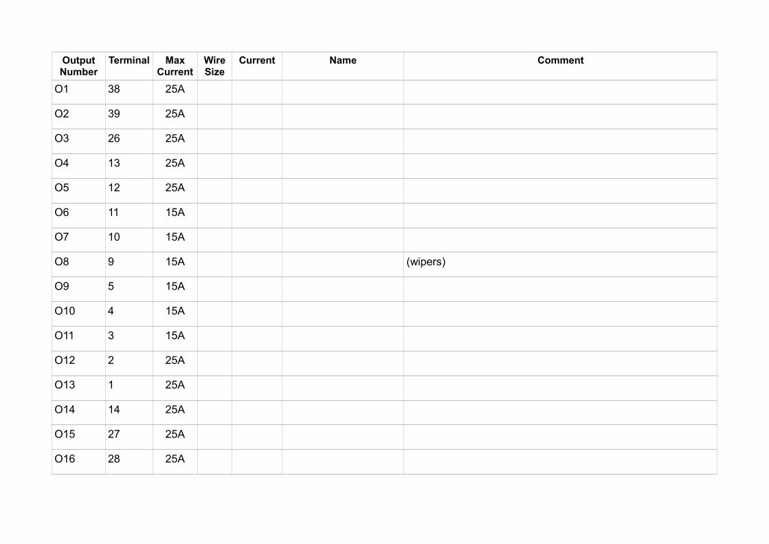
Output Pins
There are 16 output pins for you to use, 10 25A pins and 6 15A pins. They can be also used inparallel to increase current capacity (See Using output pins in parallel section)All Pins are equipped with over and under current protection, short circuit protection, as well asthermal protection. In case of any of this scenario happening, the output pin will be shut down andapropriate message will be displayed in the PMU Client and the PMU itself.For 25A Output Pins, Soft Start is available and PWM with Duty Cycle control (See PWM section)
Input Pins
There are 16 input pins for you to use as well as a separate +5V Pin to provide power for AnalogInputs such as rotary switches, or analog sensors.
PMU TEMPERATURE, PLACEMENT AND LOAD BALANCING
PMU Placement
PMU should be located in a place that protects it from weather conditions, road debris and roadhazard. Even though PMU case works as a radiator, it is also recommended to place PMUsomewhere where heat can be dissipated easily, preferably with good airflow.
PMU Temperature
PMU has three thermometers located on its board to independently measure temperature in threeseparate places.
There are two places where temperature can be checked in PMU Client, first is the status bar andthe values TL, TR, TF (Temperature Left, Temperature Right, Temperature Flash):
Second is the PMU window which can be accesed by double clicking PMU on Tree View:
Page 28
Status Bar
Thermometers location

If you are experiencing high temperatures, it is advised to move the PMU to a colder place orprovide better airflow to current location.
Output Load Balancing
Another way to handle high temperatures is to connect the devices that draw the most current in away that the transistors for their Output Pins are not grouped up together. In other words, it is agood rule of thumb not to connect devices that draw the most current to output pins whichtransistors are located next to each other. This way they can dissipate heat better, resulting inlower temperatures. Picture below shows the transistor placement for every output pin:
Page 29
Tree View → PMU window

Output Pin signaling and status
PMU has an ability to signal condition of each Power Output. It is displayed on the device itself andin PMU software. When a new Power Output is created, a special variable which represents thestatus of Power Output, called output_name.status is created as well. This variable can be used tocreate failsafes or conditions, to set up redundancy etc.
Status value in Client LED color Status
0 None Off
1 Green On
2 Orange Under Current
3 Red Over Current
Page 30
PMU output transistors location

Page 31

WIRING
Basic diagram
This is the basic PMU communication and connection diagram which contains few key elements:• PC Communication takes place on CAN 1 as this is the CAN specified to use for PC
connection.• CAN 1 has two 120 Ohm terminators on CAN bus. They are necessary, as PMU does not
provide termination on CAN 1.• CANbus Keyboard is connected to CAN 2. • Power to PMU is supplied in two ways: First using the ignition which connects to +12SW
Pin (See PMU Pinout section), second using positive battery terminal which connects to M6Bolt located on PMU case.
Page 32
PMU Basic Diagram
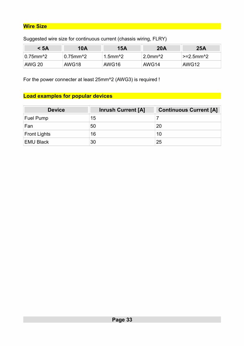
Wire Size
Suggested wire size for continuous current (chassis wiring, FLRY)
< 5A 10A 15A 20A 25A
0.75mm^2 0.75mm^2 1.5mm^2 2.0mm^2 >=2.5mm^2
AWG 20 AWG18 AWG16 AWG14 AWG12
For the power connecter at least 25mm^2 (AWG3) is required !
Load examples for popular devices
Device Inrush Current [A] Continuous Current [A]
Fuel Pump 15 7
Fan 50 20
Front Lights 16 10
EMU Black 30 25
Page 33

ANALOG INPUT WIRING
Wiring schematics
Most important thing to remember is that PMU has dedicated +5V Pin (See PMU Pinout section)can be used for things like rotary switch, active low switches and analog sensors.Below are basic wiring diagrams.
• Switch connected to GND with Pull Up
Page 34

• PMU Client configuration:
• Switch connected to +5V Pin with pull down:
Page 35
Analog Input + Pullup configuration

PMU Client configuration:
• Rotary switch
Page 36
Analog Input + Pulldown configuration

• PMU Client configuration:
Analog Sensor
To connect analog Sensor, +5V and GND Pins must be used (See PMU Pinout section). Outputfrom Analog Sensor should be connected as a regular Analog Input to PMU.
Analog Sensor diagram:
Page 37
Rotary Switch configuration
Analog Sensor diagram

PMU Client Configuration:
OUTPUT DEVICES
Power Output
Power Outputs are elements that control external devices. You can set up the Minimum Current,Maximum Current, Inrush Current, Inrush Time, PWM, and mechanisms to switch the PowerOutput on or off.
PMU Client Configuration:
Page 38
Power Output Configuration
PMU Client analog sensor configuration
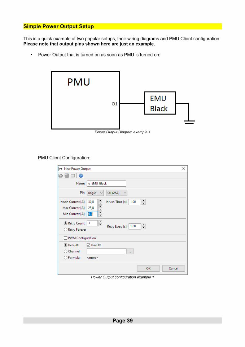
Simple Power Output Setup
This is a quick example of two popular setups, their wiring diagrams and PMU Client configuration.Please note that output pins shown here are just an example.
• Power Output that is turned on as soon as PMU is turned on:
PMU Client Configuration:
Page 39
Power Output Diagram example 1
Power Output configuration example 1

• Power Output that gets switched on by an Analog Input:
PMU Client Configuration:
Page 40
Power Output diagram example 2
Analog Input configuration example 2 Power Output configuration example 2

Wipers
To connect wipers O8 Output Pin must be used for Slow Wiper output. This is the Pin provided touse and it's the only way to use the park switch ability. For fast wiper output any output pin can beused except for O8. Park switch must be connected as an Analog Input.
.
Configuring wipers in PMU Client is pretty easy. There is a module made specifically for wiperconfiguration and should be used to set up wipers trouble-free (Project Tree → Wipers Module).PMU Client Configuration:
Page 41
PMU Client wipers configuration

Blinkers
Blinkers should be simply connected to PMU Output Pins. Three input channels should be used inthis configuration - two channels to control blinkers, one channel to control hazard lights.
PMU Client also provides special module designed to configure blinkers in easy way (Project Tree→ Blinkers Module).
Page 42
PMU Client blinkers configuration
Blinkers diagram
CANbus Keyboard
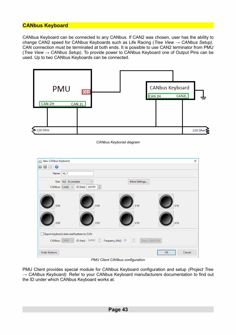
CANbus Keyboard can be connected to any CANbus. If CAN2 was chosen, user has the ability tochange CAN2 speed for CANbus Keyboards such as Life Racing (Tree View → CANbus Setup).CAN connection must be terminated at both ends. It is possible to use CAN2 terminator from PMU(Tree View → CANbus Setup). To provide power to CANbus Keyboard one of Output Pins can beused. Up to two CANbus Keyboards can be connected.
PMU Client provides special module for CANbus Keyboard configuration and setup (Project Tree→ CANbus Keyboard). Refer to your CANbus Keyboard manufacturers documentation to find outthe ID under which CANbus Keyboard works at.
Page 43
CANbus Keyborad diagram
PMU Client CANbus configuration

Power Output configuration for CANbus Keyboard:
Exporting Keyboard state
While configuring CANbus Keyboard, you can choose to broadcast the Keyboard state and buttonson chosen CANbus Interface, ID and frequency so that other device such as secondary PMU orEMU Black can acquire and use them.
If CANbus Keyboard is supposed to be used by EMU Black as well, it can be solved in thefollowing way:
– PMU controls the CANbus Keyboard, handles key switches, backlighting– PMU exports keyboard state and buttons to CAN under ID 0x0662– EMU Black reads data exported by PMU from CANbus on ID 0x0662
Using CANbus Keyboard to signal status
CANbus Keyboard can also be used as a signaling device. You can change the color of any buttonto represent either the PMU status, or any Power Output status (see Output Pin signaling andstatus section). To achieve that, a CANbus Keyboard must be configured and connected (SeeCANbus Keyboard section) and chosen button must be set up as an indicator button in PMUClient.Here is an example configuration:
Page 44
Keyboard Export
CANbus Keyboard power output configuration

This example configures button k_button1 to display the value of pmu.status channel in thefollowing way:
Status Color Description
0 None All Power Outputs are Off (pmu.status equal to 0)
1 Green At least one Power Output is on and there is no under or over currentcondition (pmu.status equal to 1)
2 Orange At least one Power Output is under current and there is no overcurrent condition (pmu.status equal to 2)
3 Red At least one Power Output is over current (pmu.status equal or above3)
Keep in mind that the button still works as a normal non-latching switch and can be set up to, forinstance, trigger Master Retry (See Master Retry Channel section) to reset all outputs.
Page 45
Keyboard status indicator configuration

Using output pins in parallel
PMU allows user to connect output pins in parallel to increase current capacity. Up to three outputpins of the same amperage can be used, granting up to 75A continuous current.
PMU Client configuration example:
INERTIA SWITCH
PMU is equipped with a failsafe switch which gets triggered in case of a crash. PMU constantlymonitors its gyroscopic values and acceleration in each axis to react quickly in the worst casescenario.
Inertia Switch
Inertia Switch immediately shuts down all Power Outputs to prevent any mishaps happening in theevent of a crash. Inertia Switch gets triggered on after exceeding acceleration threshold specifiedby user. Inertia Switch can be accessed by Tree View → Inertia Switch :
Page 46
Power Output configuration with parallel pins
Inertia Switch configuration

MASTER RETRY CHANNEL
Master Retry Channel allows user to perform reset of Power Outputs. If a Power Output hassignaled a fault, due to either over or under current condition, triggering a Master Retry will reset itback to default state. Master Retry can be triggered by any channel or element. Master Retryconfiguration can be found in Tree View → Global Output Settings → Master Retry Channel .
PWM (PULSE WIDTH MODULATION)
PMU has the ability to apply PWM to 25A Output Pins. The main principle of Pulse Width Modulation is to limit the amount of Power supplied to PowerOutput by alternating power Output on and off.
Keep in mind that PWM introduces energy loss to heat due to transistor switching on and off.Higher frequencies generate more heat, therefore If you are experiencing overheated status onPower Outputs or high heat in general, either lower the Frequency of PWM, or use a flyback diodeto eliminate flyback and lower the thermal load (See Using flyback diode section).
Page 47
Pulse Width Modulation
Master Retry configuration

Soft Start
PMU has the ability to enable a Soft Start on 25A output Pins. Soft start should be used to preventswitch-on surges of greater altitude. By varying the time on and time off with chosen frequency andduration, a Power Output reaches its state gradually.
Duty Cycle
Duty Cycle represents the percentage of time the Power Output is turned On. If the Duty cycle isset to 50%, the Power Output will be turned on for ½ of time period.
Page 48
Soft Start Disabled
PWM Disabled PWM enabled with duty cycle = 70%
Soft Start Enabled

Duty Cycle can be either set to constant value, or controlled by a Channel.
PMU Client Configuration Example:
Using flyback diode
PWM does introduce a bit of heat depending on the Device powered, and PWM settings. If you areexperiencing Overheated status on any Pulse Width Modulated Power Output, a flyback diode canbe used to eliminate flyback therefore lowering the output transistors thermal load.
Page 49
PWM Configuration example
Flyback diode diagram
USING MULTIPLE PMUs
Basic Diagram
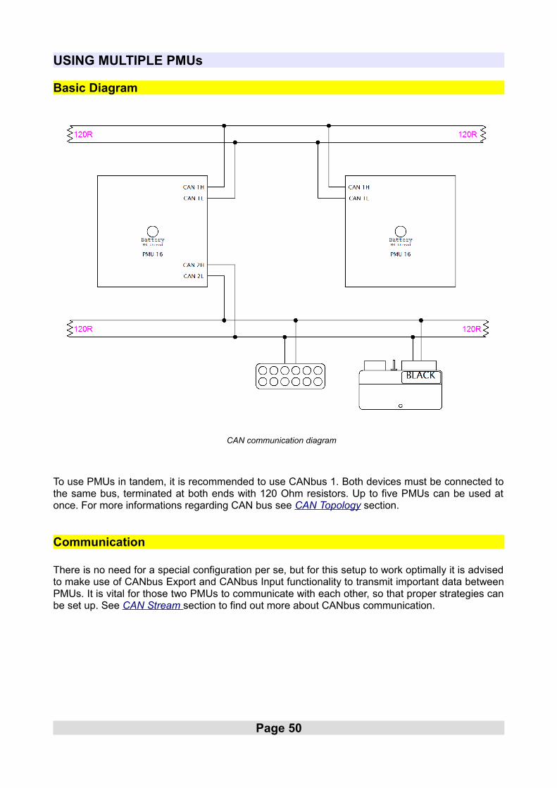
To use PMUs in tandem, it is recommended to use CANbus 1. Both devices must be connected tothe same bus, terminated at both ends with 120 Ohm resistors. Up to five PMUs can be used atonce. For more informations regarding CAN bus see CAN Topology section.
Communication
There is no need for a special configuration per se, but for this setup to work optimally it is advisedto make use of CANbus Export and CANbus Input functionality to transmit important data betweenPMUs. It is vital for those two PMUs to communicate with each other, so that proper strategies canbe set up. See CAN Stream section to find out more about CANbus communication.
Page 50
CAN communication diagram

Using PMU Client with multiple PMUs
PMU Client allows up to 5 PMUs to be connected simultaneously. You can easily switch betweenthem either using Menu Bar → Devices → Set Device #X or using Ctrl + Shift + X keyboardshortcut, where X is the device Number.
All currently connected PMUs are also displayed as a list.
Page 51
Switching between connected PMUs
List of connected PMUs

CAN STREAM
CANbus Export
CANbus Export allows user to broadcast various informations on chosen CANbus. It is essentialtool to communicate with other PMUs or ECUMASTER EMU Black device. CANbus Export can broadcast channel states, values, voltage readings, which then can be readusing CANbus Input on second PMU or EMU Black. PMU Client also allows you to save yourCANbus Export as a .CANX file. This file can be imported by any other PMU.
CANbus Export Example:
CANbus Input
CANbus Input allows user to read data from CANbus stream using CANbus Mob (See CANbusMessage Object section). You can choose the starting frame, how many bytes to read, how manybits to read and the endianess (byte order) of the data read. If a CANbus Export was created onsecondary PMU, CANbus Input (with correct CANbus Message Object) can be used to readexported parameters.
Page 52
CANbus Export
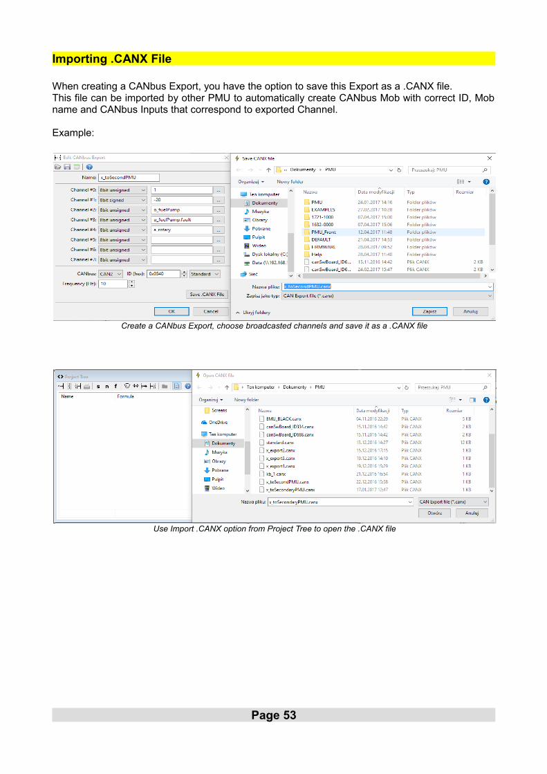
Importing .CANX File
When creating a CANbus Export, you have the option to save this Export as a .CANX file.This file can be imported by other PMU to automatically create CANbus Mob with correct ID, Mobname and CANbus Inputs that correspond to exported Channel.
Example:
Page 53
Create a CANbus Export, choose broadcasted channels and save it as a .CANX file
Use Import .CANX option from Project Tree to open the .CANX file

Page 54
As we can see, a CANbus Mob and CANbus Inputs were automatically created with correct ID

Standard CAN Stream
Standard CAN Stream(Tree View → Standard CAN Stream) gives user the ability to broadcast keyPMU parameters over CAN bus to have an oversight.Parameters themselves are predefined, but user has the ability to broadcast only some part ofthem, on chosen CAN bus with chosen ID.
Here is how CAN Stream frames are constructed:
ID BaseID + 0 Frequency: 20Hz
ByteID Channel Data Width Data Type Range Resolution Offset Unit
0 PMU Status 4 bits Unsigned 0-15 - 0 -
1 Total Current 8 bits Unsigned 0-255 1A/bit 0 A
2Battery Voltage
8 bits Unsigned 0-27.75 0.1088V/bit 0 V
3Board Temperature Left
8 bits Unsigned 0-255 1C/bit 0 C
4Board Temperature Right
8 bits Unsigned 0-255 1C/bit 0 C
5Flash Temperature
8 bits Unsigned 0-255 1C/bit 0 C
ID BaseID + 1 Frequency: 62.5Hz
ByteID Channel Data Width Data Type Range Resolution Offset Unit
0
o1.status o1.active
3 bits1 bits
Unsigned0-7 0-1
- 0 -
o2.status,o1.active
3 bits1 bits
Unsigned0-7 0-1
- 0 -
1
o3.status, o3.active
3 bits1 bits
Unsigned0-70-1
- 0 -
o4.status, o4.active
3 bits1 bits
Unsigned0-70-1
- 0 -
2
o5.status, o5.active
3 bits1 bits
Unsigned0-70-1
- 0 -
o6.status, o6.active
3 bits1 bits
Unsigned0-70-1
- 0 -
3
o7.status, o7.active
3 bits1 bits
Unsigned0-70-1
- 0 -
o8.status, o8.active
3 bits1 bits
Unsigned0-70-1
- 0 -
Page 55

4
o9.status, o9.active
3 bits1 bits
Unsigned0-70-1
- 0 -
o10.status, o10.active
3 bits1 bits
Unsigned0-70-1
- 0 -
5
o11.status, o11.active
3 bits1 bits
Unsigned0-70-1
- 0 -
o12.status, o12.active
3 bits1 bits
Unsigned0-70-1
- 0 -
6
o13.status, o13.active
3 bits1 bits
Unsigned0-70-1
- 0 -
o14.status, o14.active
3 bits1 bits
Unsigned0-70-1
- 0 -
7
o15.status, o15.active
3 bits1 bits
Unsigned0-70-1
- 0 -
o16.status, o16.active
3 bits1 bits
Unsigned0-70-1
- 0 -
ID BaseID + 2 Frequency: 62.5Hz
ByteID Channel Data Width Data Type Range Resolution Offset Unit
0 a1.voltage 8 bits Unsigned 0-5 0.0196V/bit 0 V
1 a2.voltage 8 bits Unsigned 0-5 0.0196V/bit 0 V
2 a3.voltage 8 bits Unsigned 0-5 0.0196V/bit 0 V
3 a4.voltage 8 bits Unsigned 0-5 0.0196V/bit 0 V
4 a5.voltage 8 bits Unsigned 0-5 0.0196V/bit 0 V
5 a6.voltage 8 bits Unsigned 0-5 0.0196V/bit 0 V
6 a7.voltage 8 bits Unsigned 0-5 0.0196V/bit 0 V
7 a8.voltage 8 bits Unsigned 0-5 0.0196V/bit 0 V
ID BaseID + 3 Frequency: 62.5Hz
ByteID Channel Data Width Data Type Range Resolution Offset Unit
0 a9.voltage 8 bits Unsigned 0-5 0.0196V/bit 0 V
1 a10.voltage 8 bits Unsigned 0-5 0.0196V/bit 0 V
2 a11.voltage 8 bits Unsigned 0-5 0.0196V/bit 0 V
3 a12.voltage 8 bits Unsigned 0-5 0.0196V/bit 0 V
4 a13.voltage 8 bits Unsigned 0-5 0.0196V/bit 0 V
5 a14.voltage 8 bits Unsigned 0-5 0.0196V/bit 0 V
6 a15.voltage 8 bits Unsigned 0-5 0.0196V/bit 0 V
7 a16.voltage 8 bits Unsigned 0-5 0.0196V/bit 0 V
Page 56

ID BaseID + 4 Frequency: 62.5Hz
ByteID Channel Data Width Data Type Range Resolution Offset Unit
0 o1.current 8 bits Unsigned 0-63.75 0.25A/bit 0 A
1 o2.current 8 bits Unsigned 0-63.75 0.25A/bit 0 A
2 o3.current 8 bits Unsigned 0-63.75 0.25A/bit 0 A
3 o4.current 8 bits Unsigned 0-63.75 0.25A/bit 0 A
4 o5.current 8 bits Unsigned 0-63.75 0.25A/bit 0 A
5 o6.current 8 bits Unsigned 0-63.75 0.25A/bit 0 A
6 o7.current 8 bits Unsigned 0-63.75 0.25A/bit 0 A
7 o8.current 8 bits Unsigned 0-63.75 0.25A/bit 0 A
ID BaseID + 5 Frequency: 62.5Hz
ByteID Channel Data Width Data Type Range Resolution Offset Unit
0 o9.current 8 bits Unsigned 0-63.75 0.25A/bit 0 A
1 o10.current 8 bits Unsigned 0-63.75 0.25A/bit 0 A
2 o11.current 8 bits Unsigned 0-63.75 0.25A/bit 0 A
3 o12.current 8 bits Unsigned 0-63.75 0.25A/bit 0 A
4 o13.current 8 bits Unsigned 0-63.75 0.25A/bit 0 A
5 o14.current 8 bits Unsigned 0-63.75 0.25A/bit 0 A
6 o15.current 8 bits Unsigned 0-63.75 0.25A/bit 0 A
7 o16.current 8 bits Unsigned 0-63.75 0.25A/bit 0 A
ID BaseID + 6 Frequency: 62.5Hz
ByteID Channel Data Width Data Type Range Resolution Offset Unit
0 o1.voltage 8 bits Unsigned 0-16.19 0.063V/bit 0 V
1 o2.voltage 8 bits Unsigned 0-16.19 0.063V/bit 0 V
2 o3.voltage 8 bits Unsigned 0-16.19 0.063V/bit 0 V
3 o4.voltage 8 bits Unsigned 0-16.19 0.063V/bit 0 V
4 o5.voltage 8 bits Unsigned 0-16.19 0.063V/bit 0 V
5 o6.voltage 8 bits Unsigned 0-16.19 0.063V/bit 0 V
6 o7.voltage 8 bits Unsigned 0-16.19 0.063V/bit 0 V
7 o8.voltage 8 bits Unsigned 0-16.19 0.063V/bit 0 V
Page 57

ID BaseID + 7 Frequency: 62.5Hz
ByteID Channel Data Width Data Type Range Resolution Offset Unit
0 o9.voltage 8 bits Unsigned 0-16.19 0.063V/bit 0 V
1 o10.voltage 8 bits Unsigned 0-16.19 0.063V/bit 0 V
2 o11.voltage 8 bits Unsigned 0-16.19 0.063V/bit 0 V
3 o12.voltage 8 bits Unsigned 0-16.19 0.063V/bit 0 V
4 o13.voltage 8 bits Unsigned 0-16.19 0.063V/bit 0 V
5 o14.voltage 8 bits Unsigned 0-16.19 0.063V/bit 0 V
6 o15.voltage 8 bits Unsigned 0-16.19 0.063V/bit 0 V
7 o16.voltage 8 bits Unsigned 0-16.19 0.063V/bit 0 V
Page 58

DOCUMENT REVISION HISTORY
Revision Date Changes
1.00 1.05.2017 - initial release
1.01 10.07.2017 - added information about ground connection with USBtoCAN
Page 59
OutputNumber
Terminal MaxCurrent
WireSize
Current Name Comment
O1 38 25A
O2 39 25A
O3 26 25A
O4 13 25A
O5 12 25A
O6 11 15A
O7 10 15A
O8 9 15A (wipers)
O9 5 15A
O10 4 15A
O11 3 15A
O12 2 25A
O13 1 25A
O14 14 25A
O15 27 25A
O16 28 25A

AnalogNumber
Terminal Type Pullup/Pulldown
Name Comment
A1 29
A2 16
A3 30
A4 17
A5 31
A6 18
A7 32
A8 19
A9 6
A10 33
A11 20
A12 34
A13 21
A14 8
A15 35
A16 22


