ED 362 640 AUTHOR TITLE INSTITUTION SPONS AGENCY PUB DATE NOTE PUB TYPE EDRS PRICE DESCRIPTORS IDENTIFIERS ABSTRACT DOCUMENT RESUME CE 064 309 Brown, Tim; And Others Physics for the Technologies. Supplementary Units. Partnership for Academic and Career Education, Pendleton, SC.; Tri-County Technical Coll., Pendleton, S.C. Society of Manufacturing Engineers, Dearborn, MI. Mar 91 58p. Guides Classroom Use Teaching Guides (For Teacher) (052) MF01/PC03 Plus Postage. Academic Education; High Schools; *Integrated Curriculum; *Laboratory Experiments; Laboratory Procedures; Learning Activities; *Physics; *Science Experiments; *Science Instruction; Technology; *Technology Education; Units of Study; Vocational Education Tech Prep These supplemental units contain four laboratory exercises that can be used to enhance the labs in "Physics for the Technologies." The four units (one mechanical, two thermal, and one electrical) are designed to enhance labs in presenting specific concepts. Each unit can be used as an example of how the concepts behind the theory apply to real-world situations. Introductory materials list the units in which they can be used as additional exercises, offer suggestions for presenting the supplementary units, list necessary equipment, and offer two options for obtaining equipment the high school may not have. Each unit consists of these components: introduction (lab objective, learning path, and main idea); teaching path with list of resource materials, class goals, and class activities; discussion (information); and laboratory (equipment, procedures, and additional exercises). Topics are as follows: mechanical bending stress, measuring heat flow using an electrical analog, electrical energy storage in capacitors, and measuring thermal power. (YLB) *********************************************************************** Reproductions supplied by EDRS are the best that can be made * from the original document. ***********************************************************************
Transcript
ED 362 640
AUTHORTITLEINSTITUTION
SPONS AGENCYPUB DATENOTEPUB TYPE
EDRS PRICEDESCRIPTORS
IDENTIFIERS
ABSTRACT
DOCUMENT RESUME
CE 064 309
Brown, Tim; And OthersPhysics for the Technologies. Supplementary Units.Partnership for Academic and Career Education,Pendleton, SC.; Tri-County Technical Coll.,Pendleton, S.C.Society of Manufacturing Engineers, Dearborn, MI.Mar 9158p.
Guides Classroom Use Teaching Guides (ForTeacher) (052)
MF01/PC03 Plus Postage.Academic Education; High Schools; *IntegratedCurriculum; *Laboratory Experiments; LaboratoryProcedures; Learning Activities; *Physics; *ScienceExperiments; *Science Instruction; Technology;*Technology Education; Units of Study; VocationalEducationTech Prep
These supplemental units contain four laboratoryexercises that can be used to enhance the labs in "Physics for theTechnologies." The four units (one mechanical, two thermal, and oneelectrical) are designed to enhance labs in presenting specificconcepts. Each unit can be used as an example of how the conceptsbehind the theory apply to real-world situations. Introductorymaterials list the units in which they can be used as additionalexercises, offer suggestions for presenting the supplementary units,list necessary equipment, and offer two options for obtainingequipment the high school may not have. Each unit consists of thesecomponents: introduction (lab objective, learning path, and mainidea); teaching path with list of resource materials, class goals,and class activities; discussion (information); and laboratory(equipment, procedures, and additional exercises). Topics are asfollows: mechanical bending stress, measuring heat flow using anelectrical analog, electrical energy storage in capacitors, andmeasuring thermal power. (YLB)
Reproductions supplied by EDRS are the best that can be made *
from the original document.***********************************************************************
U.S DEPARTMENTOf EDUCATIONOthce ot EaucahonsiRofearch nd Improvratro
EDUCATIONAL RESOURCES INFORMATIONCENTER (ERIC,
Vh.s OcCur0001 has Peen raor0Oucg4 *it1eCe/.1t0 1,00, the 011300 0, pganuationOncpna talc) a
C Mnot changes hae bemn mule to mnpeor1erarOcluCt,011 Qua lay
Pwas of OP rr,ons Stated11.1th1Sdoc.men! 00 001 necessanly reprsent othciatOE RI oosaron or porrcy
"PERMISSION TO REPRODUCE THISMATERIAL HAS BEEN GRANTED BY
TO THE EDUCATIONAL RESOURCESINFORMATION CENT, (ERICr
PHYSICS FOR THETECHNOLOGIES
Supplementary Units
Dr. Tim BrownDepartment Head
Automated Manufacturing TechnologyTri-County Technical College
Developed by:
Mr. Ron TalleyDepartment Head
Electronic Engineering TechnologyTri-County Technical College
With Special Assistance From:Louisa Fleming, Liberty High School
Cheryl Murphy, Walhalla High SchoolHarriet Palmer, Pendleton High School
Michael 'Lucky Voiselle, Mc Duffle High SchoolDr. Jim Wood, Chairman, Industrial& Engineering Technology Division,
Tri-County Technical College
This project was made possible through a grant awarded to the Industrial and EngineeringTechnology Division of Tri-County TechnicalCollege by the Society of Manufacturing Engineers.
Published by:The Partnership for Academic and Career Education (PACE)
P. 0. Box 587Pendeton, SC 29670
803-646-8361, extension 2247(March, 1991)
2
BEST COPY MUM
TABLE OF CONTENTS
INTRODUCTIONWhat Is in These UnitsWhere to Use the UnitsLesson OutlineSuggestions for UseEquipment
UNIT I: MECHANICAL BENDING STRESSIntroductionTeaching PathDiscussionLaboratory
UNIT II: MEASURING HEAT FLOW USING AN ELECTRICAL ANALOGIntroductionTeaching PathDiscussionLaboratory
UNIT III: ELECTRICAL ENERGY STORAGE IN CAPACITORSIntroductionTeaching PathDiscussionLaboratory
UNIT IV: MEASURING THERMAL POWERIntroduction 42Teaching Path 43Discussion 47Laboratory 50
PHYSICS FOR THE TECHNOLOGIESSUPPLEMENTARY UNITS
What is in these units?The Supplementary Units contain four laboratory exercises
which can be used to enhance the labs in Physics for theTechnologies. Each unit contains a lab objective, discussionsections and laboratory exercises. The equipment needed tocomplete each lab is listed at the beginning of the exercise.(See EQUIPMENT section on how to obtain equipment that the localschool may not have.)
Where to use the units.The four units (one mechanical, two thermal and one
electrical) are designed to enhance labs in presenting specificconcepts. Each unit can be used as an example of how theconcepts behind the theory apply to real-world situations. Thesupplementary units can be used as additional exercises in thefollowing units:
Unit I: "Mechanical Bending Stress" a lab exercise forForce in Mechanical Systems;
Unit II: "Measuring Heat Flow Using an Electrical Analog" alab exercise for Rate in Thermal Systems;
Unit III: "Electrical Energy Storage in Capacitors" a labexercise for Energy in Ele:trical Systems;
Unit IV: "Observing Thermal Power" a lab exercise forPower in Thermal Systems.
Please keep in mind that the above listing is only a suggesteduse of the units. If the teacher so desires, the units can beused in other units or subunits. Also, these units are for thefirst year of Physics for the Technologies. Teachers who teach atwo-year sequence, may wish to modify the units somewhat and ulethem as part of the second-year course.
Lesson Outline for each Unit
Introduction: Lab Objective, Learning Path, Main Idea
Teaching Path: Resource Materials, Class Goals, ClassActivities
In order to provide a variety of learning experiences, thefollowing suggestions may be helpful in presenting thesupplementary units:
Consider using teams of instructors to present the ideas andconcepts. These teams may consist of high school facultyfrom academic and vocational areas, high school andtechnical college faculty, or high school faculty and anindustry representative. If someone outside the schoolsetting is to be invited, it is suggested that theindividual be notified well in advance of the scheduled dateso that he/she will have ample opportunity to prepare forthe class.
Make arrangements for high school classes to visit labs onthe campus of Tri-County Technical College. Teacherswishing to take students to Tri-County Technical Collegeshould contact Dr. Jim Wood, Chairman, Industrial andEngineering Technology Division. (Telephone 646-8361,225-2250 :Anderson County], 859-7033 [Pickens County], or882-4412 [Oconee County] extension 2176 or 2285.) Dr. Woodcan provide the name of the appropriate department head tocontact in order to arrange for the visit to Tri-County.
Plan field trips which center around the concepts beingpresented in the particular lesson. Local industries canprovide students with the opportunity to see how theconcepts being presented in the classroom are applied in theworkplace. If field trips are to be used, call the industryand explain what the field trip is about, what concepts arebeing presented in the classroom, and tell the industryrepresentative you would like for him to provide studentswith the opportunity to see how the skills being taughtrelate tc, the workplace.
Invite outside speakers to address the class. When invitinga guest speaker, it would be helpful to the speaker toprovide some preliminary information about the conceptsbeing covered in class. Speakers may be able to bringexamples of machines from the workplace which demonstrateconcepts being presented in class. The Guide to AreaBusiness Speakers, published by the Partnership for Academicand Career Education, is an excellent source for speakers.
2 5
EQUIPMENT
Rulers (centimenters)Meter sticksDeep-throat C-clampWood stripsStrips of materials
(metals or plastics)DC power supply
(at least 12-V.)Voltmeter or DMMAmmeter or VOMRing clampsTurbine diffuserWeights
(1/2-kg., 1-kg., 2-kg.)Switches (various)
Test block with wire clamps5300 microfarad capacitor15000 microfarad capacitor1000-ohm resistor12-V. lamp (100 milliamp or
smaller)Timer with minutes and secondsBunsen burnerRing standsClampsTurbineThermocouple and multimeterWeight hanger
(1-kg. type)
Laboratory exercises in these modules may require the use ofequipment which the local high school science department mightnot have readily available. If the high school does not have theequipment, there are two ways to obtain this equipment.
Option One is to have the local industrial technology educationclasses constrrct the equipment. Blueprint drawings of neededequipment are contained in each module which requires specializedequipment.
Option Two is to requesl-. the needed equipment from the Industrialand Engineering Technology Division at Tri-County TechnicalCollege. If equipment is to be requested from Tri-County, pleasegive two to three weeks' notice so the materials can be collectedand placed in the division's office for dissemination. Torequest materials from rri-County contact Dr. James Wood,Chairman, Industrial and Engineering Technology Division, Tri-County Technical College. Telephone 646-8361, 225-2250 (AndersonCounty), 859-7033 (Pickens County), or 882-4412 (Oconee County)extension 2176 or 2285.
3
6
UNIT I
MECHANICAL BENDING STRESS
4
MECHANICAL BENDING STRESS Lab IM3
LAB OBJECTIVE
When you've finished this lab, you should be able to do thefollowing:
1. Measure the deflection of a beam subjected to bending stress.
2. Calculate the resistance of a beam to bending stress.
LEARNING PATH
1. Preview the lab. This will give you an idea of what'sahead.
2. Read the lab. Give particular attention to the labobjectives.
3. Do the lab "Mechanical Bending Stress."
MA/N IDEA
* A beam which is loaded by a force placed at some distance fromits restrained end will deflect or bend.
* ThB degree of beam deflection depends on the magnitude of loadapplied, the material from which the beam is constructed andthe distance between the load and the restrained end of thebeam.
5
TEACHING PATH - CLASS L3
(Students should have read this lab before proceeding,mostly to familiarize them with the nature of the lab to becompleted and the equipment to be used.)
RESOURCE MATERIALS
Lab 1M3: "Mechanical Bending Stress"
CLASS GOALS
See OBJECTIVES for Lab 1M3.
CLASS ACTIVITIES
Set up the lab and run through the procedures before thestudents try the lab. You'll be able to anticipate studentdifficulties.
1. Preview the lab for the students and explain what it isabout. Show students the equipment and tell them what theyare to accomplish.
2. Have the students follow the procedures outlined in the labinstructions. Encourage them to read the procedurescarefully. (Reading detailed procedures and followinginstructions are important parts of a technician'straining.)
3. Monitor student progress and provide help as needed.
4. Before coming to the next class, you should review print/video material on "Force in Mechanical Systems." Askstudents to review the objectives and main ideas inpreparation for Class R, a review of the subunit, "Force inMechanical Systems."
NOTE: Before class, cut strips of the materials which yourstudents will use in the bending tests. These stripsshould be 30 cm long by 2 cm wide by 2 mm thick, with ahole to insert the weight hanger at one end. Also, cutstrips of wood 10 cm long by 3 cm wide by 1 cm thick tohelp clamp the bending test strips to a table.
6
DISCUSSION
If we load a beam at a distance from its restrained (orsupported) end, the beam will deflect (or bend). The bending of aloaded beam is shown in Figure 1 below.
1
(a) Bean Without a Load
I
!APPLIEDLOAD
1 F
--......)
(b) Bean with a Load
Figure 1 Beam without a load and after loading
The load placed on the beam has caused a mechanical stress in thebeam material. This mechanical stress causes a tension stress inthe top of the beam and a compression stress in the lower part ofthe beam. Somewhere between the top and bottom sides of the beam(as the stress changes from tension to compression), the stressis zero. This plane of zero beakt stress is called the neutralsurface. The stress profile in Figure 2 illustrates the idea ofthe neutral surface.
7
10
TENSION
AN-
am-
NEUTRAL SURFACE
COMPRESSION
Figure 2 Stress profile in a loaded beam
Figure 3 below illustrates tAle parameters of a beam cross sectionwhich are used to calculate the stresses and deflection of thebeam.
i APPLIEDLOAD
r- C
L
APPLIEDLOAD
H. I° "IdL NEUTRAL
SURFACE
NV
Figure 3 Beam stress and deflection parameters
8
1 1
MOMENT OF INERTIA OF BEAMS
The ability of a beam to resist bending stresses depends on thetype of material from which the beam is constructed and thedistribution of the material in the beam in relationship to thedirection of the load.
The distribution of the beam material in relition to thedirection of the load is quantified as the "moment of inertia" ofthe beam about the neutral surface.
Some formulae for moments of inertia of beams are
Rectangular Beam Cross Sections
I = b * h312
(1)
where I = moment of inertia about the neutralsurface
b = width of beam (perpendicular to load)
h = depth of beam (parallel to load)
Round Beam Cross Sections
I = PI * d4 (2)64
where PI = pi or 3.141592654...
BENDING STRESS IN BEAMS
The bending stress in a beam is produced by loading the beam at adistance from its restrained (or supported) end. Figure 4 belowillustrates a cantilever beam loading.
Figure 4 Cantilever Beam Loading
9
12
In the cantilever beam, the effect of the loading force is toproduce a moment. The moment of the cantilever beam shown inFigure 4 is
M = F * L
where M = the moment on the beam
F = the force on the beam
(3)
L = the distance from the beam support tothe load force PERPENDICULAR to the loadforce
The stress in a beam can be calculated from
S = M * v (4)
wh!=tre S = stress in the beam at a distance of vfrom the neutral surface
v = distance from the neutral to the pointat which the stress is calculated (let'scall x "POSITIVE" if it is ABOVE theneutral surface and "NEGATIVE" if it isBELOW the neutral surface)
I = the moment of inertia of the beam
If the distance from the neutral surface at which we calculatethe stress is c (the distance from the neutral surface to theoutside surface of the beam), then we calculate the maximumstress in the beam (tension if S is + and compression if S is -)or
S = M * Cmax
10
13
(5)
DEFLECTION IN BEAMS
When a beam is loaded in cantilevered fashion, the free end ofthe beam will be deflected or bent downward as shown in Figure 5below:
X
-i-Yriax
Figure 5 Deflection of a cantilevered beam
The value of the beam deflection can be calculated from theequation
y = M * x22E * I
where y = the beam deflection
M = the moment on the beam
( 6)
x = the distance from the supported end ofthe beam to the point at which thedeflection is being calculated
E = the modulus of elasticity of thematerial from which the beam isconstructed
I = the moment of inertia of the beam
If the distance from the supported end of the beam is equal tothe distance from the supported end of the beam to the loadforce, then the deflection will be its maximum value. Thismaximum value of deflection can be calculated from the equation
Yinim = M * L? (7 )
2E * I
11.
1 4
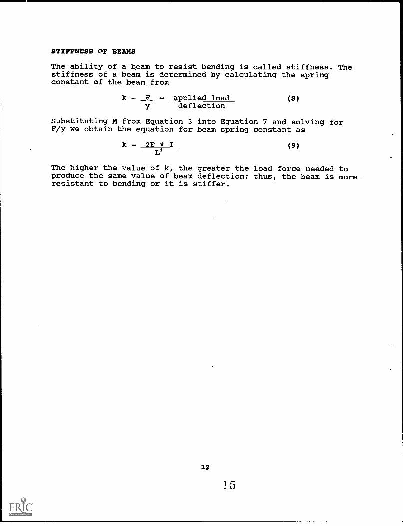
STIFFNESS OF BEAMS
The ability of a beam to resist bending is called stiffness. Thestiffness of a beam is determined by calculating the springconstant of the beam from
k = F = applied load (8)deflection
Substituting M from Equation 3 into Equation 7 and solving forF/y we obtain the equation for beam spring constant as
k = 2E * I (9)
The higher the value of k, the greater the load force needed toproduce the same value of beam deflection; thus, the beam is more.resistant to bending or it is stiffer.
12
15
Laboratory
EQUIPMENTRuler (centimeters)Meter stickWeights (1/2-kg., 1-kg., 2-kg.)Weight hanger, 1-kg. typeDeep-throat C-clampWood strip (approximately 10 cm long X 3 cm wide X 1 cm thick)Strips of material (approximately 30 cm long X 2 cm wide X 2 mm
thick) (various metals and plastics should be used)
PROCEDURES
1. Secure a strip of material to the edge of a table using the C-clamp and wood strip, allowing 20 cm of the strip to hang overthe edge of the table. See Figure 6 below. [CAUTION!!! Becareful not to put your feet under the test sample or weighthanger at any time. If the C-clamp slips, there could be someserious injuries.]
EDGE CIF TABLE
AND Z WHEN WEIGHTSARE ADDED
Figure 6
2. Measure and record, in Data Table 1, the distance from theedge of the wood strip to the center of the weight hangerhole. This is the variable L.
13
16
3. Measure and record, in Data Table 1, the distance from thefloor to the test sample (at the weight hanger). This is thedistance Zo.
4. MeasureThis is
5. Attachrecordsample
and record, in Data Table 1, the weight hanger weight.the variable Wo.
the weight hanger to the test specimen; measure andin Data Table 1 the distance from the floor to the test(at the weight hanger). This is the variable Z.
//
6. Calculate the deflection by subtracting the loaded distancefrom the unloaded distance and record the difference in DataTable 1. This is the variable y .
7. Repeat Step 5 using the 1/2-kg, 1-kg and 2-kg. weights. Recordthe weights and deflections in Data Table 1.[CAUTION!!! DO NOTforget to add the weight of the hanger to that of the attachedweights.] This is the Variable F = W + Wo.
8. If you wish to test various samples of materials, make copiesof Data Table 1 and repeat Steps 1 through 6 for each of thesamples.
DATA TABLE 1L = cm.Zo = cm.Wo = kg.
Test Z Zo yrnax=Z-Zo W Wo F=W-Wo
1
2
3
4
14
17
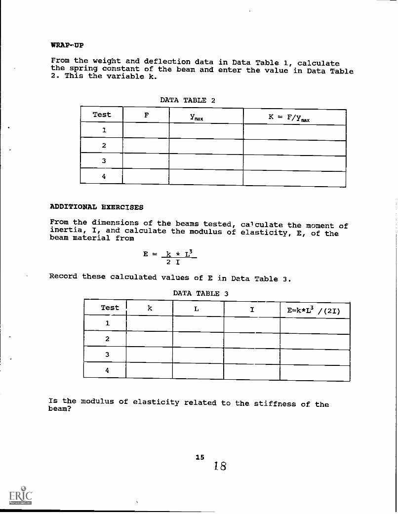
WRAP-UP
From the weight and deflection data in Data Table 1, calculatethe spring constant of the beam and enter the value in Data Table2. This the variable k.
DATA TABLE 2
Test F Ymx K = F/yrim
1
2
3
4
ADDITIONAL EXERCISES
From the dimensions of the beams tested, calculate the moment ofinertia, I, and calculate the modulus of elasticity, E, of thebeam material from
E = k *2 I
Record these calculated values of E in Data Table 3.
DATA TABLE 3
Test k L I E=k*I3 /(2I)
1
2
3
4
Is the modulus of elasticity related to the stiffness of thebeam?
15
is
UNIT II
MEASURING HEAT PLOW US/NG AN ELECTRICAL ANALOG
16
1J
MEASURING HEAT FLOW USING AN ELECTRICAL ANALOG Lab 3T3
LAB OBJECTIVE
When you've finished this lab, you should be able to analyze theheat flow through any material composition or geometry using theanalogy between heat conduction through a thermal resistance andelectrical current flow through an electrical resistance.
LEARNING PATH
1. Preview the lab. This will give you an idea of what's ahead.
2. Read the lab. Give particular attention to the labobjectives.
3. Do the lab, "Measuring Heat Flow Using an ElectricalAnalog."
MAIN IDEA
* Analogues allow tests to be performed on test devices in amanner much less tedious than if the test were performed on anactual device.
17
0
TEACHING PATH - CLASS L3
RESOURCE MATERIALS
Lab 3T3: "Measuring Heat flow Using an Electrical Analog"
CLASS GOALS
See OBJECTIVES for Lab 3T3
CLASS ACTIVITIES
Set up the lab and run through the procedures before the studentstry the lab. You'll be able to anticipate student difficulties.
1. Preview the lab for the students and explain what the lab isabout. Show students the equipment and tell them what theyare to accomplish.
2. Have the students follow the procedures outlined in the labinstructions. Encourage students to read the Procedurescarefully. (Reading detailed procedures and followinginstructions are important parts of a technician'straining.)
3. Monitor student progress and provide help as needed.
The test block can be built using the attached drawing "CornerBlock Drawing". Students in the school's shop classes can makethe test block using aviation snips.
Make photocopies of the "Test Block Pattern" and the "WiringClamp Pattern" and use these copies for a pattern by which to cutthe sheet metal. CAUTION: When working with sheet metal, becareful not to be cut by the sharp edges.
NOTE: For temperature difference across a wall to be accuratelysimulated, the wire clamps must be connected to the test block toensure uniform application of voltage.
18
21
To further study the effect of geometry on heat flow rate, cutout different test blocks and wiring clamps to simulate differentcorner block shapes. You are only limited by your own imaginationwhen simulating heat flow using the electrical analog.
By measuring the voltage between any point on the test block andpower supply ground (-), you may determine the "temperature" atthat point by using the temperature versus voltage scale factor.By placing a grid on the Test Block and measuring the voltages atthe grid intersections, a temperature profile can be obtained forthe corner block. Engineers use such temperature profiles toreduce the heat lost from buildings or to study the heat flowthrough newly designed machines without having to actually buildthe machine. CAUTION: Observe all safety procedures used whenworking with electrical devices.
19
22
ROOM
TEMPERATURE
25 DEG, C
+20
VD
C
1.0L
=20
cm
1111
1111
1111
11
1111
1111
1111
11
WA
LL M
AT
ER
IAL
---,[OUTDOOR
TEMPERATURE
5 DEG, C
70.5
cm
k= 0
.125
cal
/sec
-cm
-cm
-C/c
m
ROOM CORNER BLOCK
clam
p
L=1.
9cm
AM
ME
TE
R
/V
OLT
VM
ET
ER
grou
ndte
st b
lock
MA
TE
RIA
L' 2
0 G
auge
Alu
min
umS
heet
s
WIRING CLAMP PATTERN
NO
TE
1
1. C
lam
p w
ire c
lam
ps s
ecur
ely
and
unifo
rmly
to th
ete
st b
lock
2.S
olde
r po
wer
sup
ply
wire
s to
cla
mps
at
1/32
Inch
dril
led
hole
s
clam
p
grou
nd0
TEST SET, UP
6.7c
m
MA
TE
RIA
L' 2
0 G
auge
Alu
min
umS
heE
TEST BLOCK PATTERN
24
CO
RN
ER
BLO
CK
DR
AW
ING
DISCUSSION
ANALOGUES are dissimilar mechanisms which correspond in some wayto each other. In plain English, analogues are physicallydifferent but operate in a similar manner.
WHAT IS AN ELECTRICAL ANALOG FOR HEAT FLOW?
Scientists and engineers have developed certain "laws" tomathematically describe or predict the operation of physicalsystems. These laws are expressed as formulae or equations.
The law which describes heat flow by conduction across an object(such as shown in Figure 1) is:
Q = hzu Lr 2 - T11
where Q = heat flow rate (thermal rate)
k = thermal conductivity of the objectthrough which the heat is "flowing"
A = surface area of the object (atright angles to the direction ofheat flow)
L = thickness of the object (in thedirection of heat flow)
T2= temperature on the "hot" side of theobject
T1= temperature on the "cold" side ofthe object
HOT SIDE---s-1 L
MaterialThermal
Conductivity
T2
HEAT FLOW
COLD SIDET1
Figure 1 Conduction Heat Flow
21
25
The law which describes the flow of electrical current through anobject (such as shown in Figure 2) is:
I = VR
where I = current (flow of charge)
V = voltage drop across the object
R = electrical resistance of the object
This equation is known as Ohm's Law.
Figure 2 Electrical Current Flow
Thus, by looking at the similarities between the heat flowequation and Ohm's Law, we can determine the analog quantities asshown in Table 2.
TABLE 2
Type of Quantity Ohm's Law Heat Flow Equation
Rate I Q
Driving Force V T2 - T1
Resistance R L/kA
In fact, almost any rate "Law" can be expressed as
Rate = Driving ForceResistance
22
26
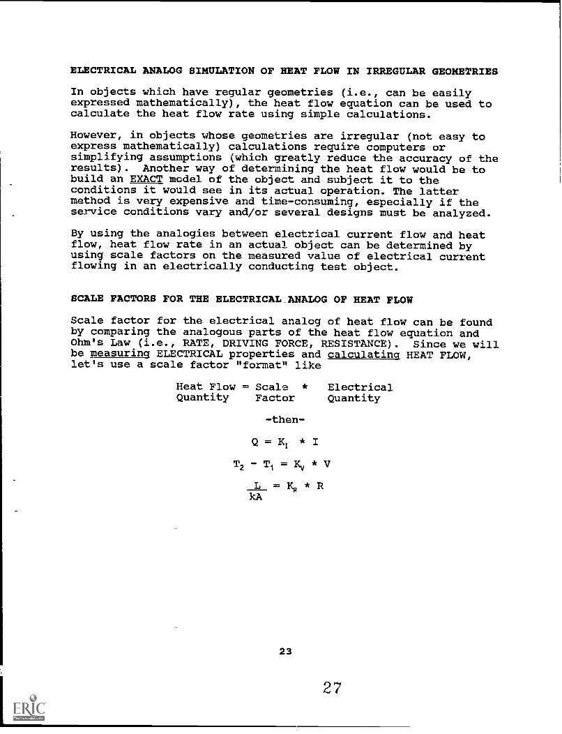
ELECTRICAL ANALOG SIMULATION OF HEAT FLOW IN IRREGULAR GEOMETRIES
In objects which have regular geometries (i.e., can be easilyexpressed mathematically), the heat flow equation can be used tocalculate the heat flow rate using simple calculations.
However, in objects whose geometries are irregular (not easy toexpress mathematically) calculations require computers orsimplifying assumptions (which greatly reduce the accuracy of theresults). Another way of determining the heat flow would be tobuild an EXACT mcdel of the object and subject it to theconditions it would see in its actual operation. The lattermethod is very expensive and time-consuming, especially if theservice conditions vary and/or several designs must be analyzed.
By using the analogies between electrical current flow and heatflow, heat flow rate in an actual object can be determined byusing scale factors on the measured value of electrical currentflowing in an electrically conducting test object.
SCALE FACTORS FOR THE ELECTRICAL.ANALOG OF HEAT FLOW
Scale factor for the electrical analog of heat flow can be foundby comparing the analogous parts of the heat flow equation andOhm's Law (i.e., RATE, DRIVING FORCE, RESISTANCE). Since we willbe measuring ELECTRICAL properties and calculating HEAT FLOW,let's use a scale factor "format" like
but remember the equation for resistance of a conductor is
R = rho *K
AR
K1
where rho= resistivity of the object
'JR = thickness of object (in direction of current)
AR = cross-sectional area of object (perpendicular todirection of current)
By substituting KR in the equation for R and rearranging we have
KR = kit421.11k(rho)
-and-
K = Q
Since Q=k * A0(T2-T1)/42 and I =V/R (or V * AR/(rho *substituting these values into the K/ equation and rearranging,we have
K/ = k * A0(T2-T11 * rho * IJR -or-V * A,R
K/ = AoLRk(rho) * 112 - T11
Nit VTHUS-
K/ =KR
Using these scale factors and the analog equations, we candetermine the heat flow rate of an object by measuring thecurrent through a test object.
24
28
SUMMARY OF ELECTRICAL ANALOG OF HEAT FLOW EQUATIONS
Let's arrange these equations simply in the order in which theywill be used to determine an object's heat flow by measuring thecurrent in our test object.
SCALE FACTOR EOUATIONS
ANALOG EQUATIONS
KR = ARLOAtyc(rho)
EY = 4=211V
=KR
Q = K/1
VARIABLES NEEDED TO USE THE ANALOG METHOD OF TESTING
AR = length of straight side X thickness of TEST object
At = length of straight side X thickness of ACTUALobject
It = length of short side of ACTUAL object(perpendicular to AO
= length of short side of TEST object (perpendicularto Att)
k = thermal conductivity of ACTUAL object
rho= resistivity of TEST object
T2 = "hot side" temperature of ACTUAL object
Tl = "cold side" temperature of ACTUAL object
V = voltage drop across TEST object
ALUES MEASURED FROM THE ELECTRICAL TEST OBJECT
I = current through the test object
VALUES CALCULATED FOR THE ACTUAL OBJECT
Q = heat flow through the object
25
MEASURING THE HEAT LOSS FROM A ROOM CORNER BLOCK
In order to make the electrical analog of heat flow useful, let'sapply the technique to measuring the heat flow from part of abuilding wall. Figure 3 below shows the actual object to betested:
I
I OUTDOOR, TMPERATURETEMPERATURt z-
25 DEG. C Dz-G CI 5 -
ROOM
70.5cr,
WALL MATERIALk= 0.125 coA/sec-cm-cm-C/cm
Figure 3 Room Corner Block
In Figure 3 we have shown a top view of the corner of a room inthe building for which we will be measuring heat loss. In orderto perform the test, we first must calculate the scale factorsfor the electrical analog of heat flow (We will assume theoutdoor face of the corner block is 250 cm "thick" and that thereis no heat loss from the two faces perpendicular to the outdoorfaces, the top of the corner or the bottom of the corner).Figure 4 below shows the test block we will use to simulate theactual block in the corner of the room:
+20 VDC
clamp
L.1.90.1110.
AMMETER
VOLTMETER
ground test block
clamp
ground6.7cr,
Figure 4 Test Block
26
30
VARIABLES NEEDED TO USE THE ANALOG METHOD OF TESTING
= 6.7 cm * 0.0934 cm* = 0.626 cm2
AQ = 70.5 cm * 250 cm = 17,625 cm2
= 20 cm
= 1.9 cm
k = 2.17 watts/cm-deg C*
rho= 2.688 * 10-6 ohm-cm*
T2 = 25 deg C
TI = 5 deg C
V = 20 volts
* Values from Handbook of Engineering Fundamentals John Wiley andSons, Inc. publisher
Q(watt) = (5.831 * 10-3 watt/ma)I(ma) ANALOG EQUATION TO USEIN LAB
CONCLUSIONS
Thus, by measuring the current flow, I, through the test block,we can calculate the heat flow, Q, through the corner (actual)block.
By changing the variables and test block geometry, we canrecalculate the analog equation and test any other heat flow wewish.
28
32
Laboratory
EQUIPMENT
DC Power SupplyVoltmeter or DMMAmmeter or VOMTest Block with Wire Clamps
PROCEDURES
1. Hook the power supply to the test block as silown in Figure 1below:
AMM
VCILTMETER
ground
Figure 1
2. Adjust the voltage across the test block to 20 volts DC.(This simulates a 20° C temperature difference between theoutside and inside walls of the corner block)
3. Measure the current through the test block and record thevalue below in Data Table 1:
NOTE: Ycu may want to simulate other temperature differencesacross the corner block; if so, record the currentthrough the test block for the other voltage drops shownin Data Table 1. REMEMBER: If you change the voltagedrop you MUST recalculate K and K1.
29
DATA TABLE 1
Voltage acrossTest Block (volts)
Current throughTest Block (milliamps)
Heat Flow(watts) K/ * I
20
5
10
15
25
30
WRAP-UP
Now we have seen one method scientists and engineers use to findout what will happen to a particular device they have designedwithout having to build a full-scale, working model.
There are many ways to SIMULATE the operation of an actual deviceby measuring the effects on a much smaller and less expensivetest device. Two of these ways include
Wind tunnel testing of models of aircraft and mockups totest the passenger comfort in a new automobile.
A very modern way of simulation involves using computers to makenumerous calculations of the various parameters of a device todetermine how the device will perform under various operatingconditions. In the future, many people will be employed in theseareas of Computer Aided Design (CAD) using computers to speed upthe design process.
Can you think of any examples of using a simple test to determinethe operation of another device?
30
34
UNIT III
ELECTRICAL ENERGY STORAGE IN CAPACITORS
3 3.
35
ELECTRICAL ENERGY STORAGE IN CAPACITORS Lab 5E1
LAB OBJECTIVES
When you've finished this lab, you should be able to do thefollowing:
1. Describe the construction of a capacitor.
2. Explain how a capacitor stores energy.
3. Calculate the charge on a capacitor, given its size and thevoltage across it.
4. Calculate the instantaneous voltage across a capacitor in aresistor-capacitor (RC) network.
5. Calculate the approximate time required to fully charge acapacitor in an RC circuit.
LEARNING PATH
1. Preview the lab. This will give you an idea of what's ahead.
2. Read the lab. Pay particular attention to the labobjectives.
3. Do the lab, "Electrical Energy Storage in Capacitors."
MAIN IDEAS
Capacitors store and discharge electrical energy.
The amount of energy stored is determined by the size of thecapacitor and the electrical potential across its terminals.
The rate of charge and discharge of the capacitor isdetermined by its size and the resistance of the charging ordischarging path.
A large capacitor can store enough energy to briefly light asmall lamp.
32
36
TEACHING PATH - CLASS Ll
Note: Students should have read this lab before proceeding,mostly to familiarize themselves with the nature of the lab to becompleted and the equipment to be used.
RESOURCE MATERIALS
Lab 5E1: "Electrical Energy Storage in Capacitors"
CLASS GOALS
See OBJECTIVES for Lab 5E1.
CLASS ACTIVITIES
(Set up the lab and run through the procedures beforestudents try it. You'll be able to anticipate studentdifficulties.)
1. Preview the lab for students and explain what it is about.Show students the equipment and tell them what they need toaccomplish.
2. Have students follow the Procedures outlined in the labcarefully. (Reading detailed procedures and followinginstructions are important parts of a technician'straining.)
3. Monitor student progress and provide help as needed.
4. Ask students to read Lab 5E2, "Converting Fluid Energy toElectrical Energy," before doing the next lab.
33
37
DISCUSSION
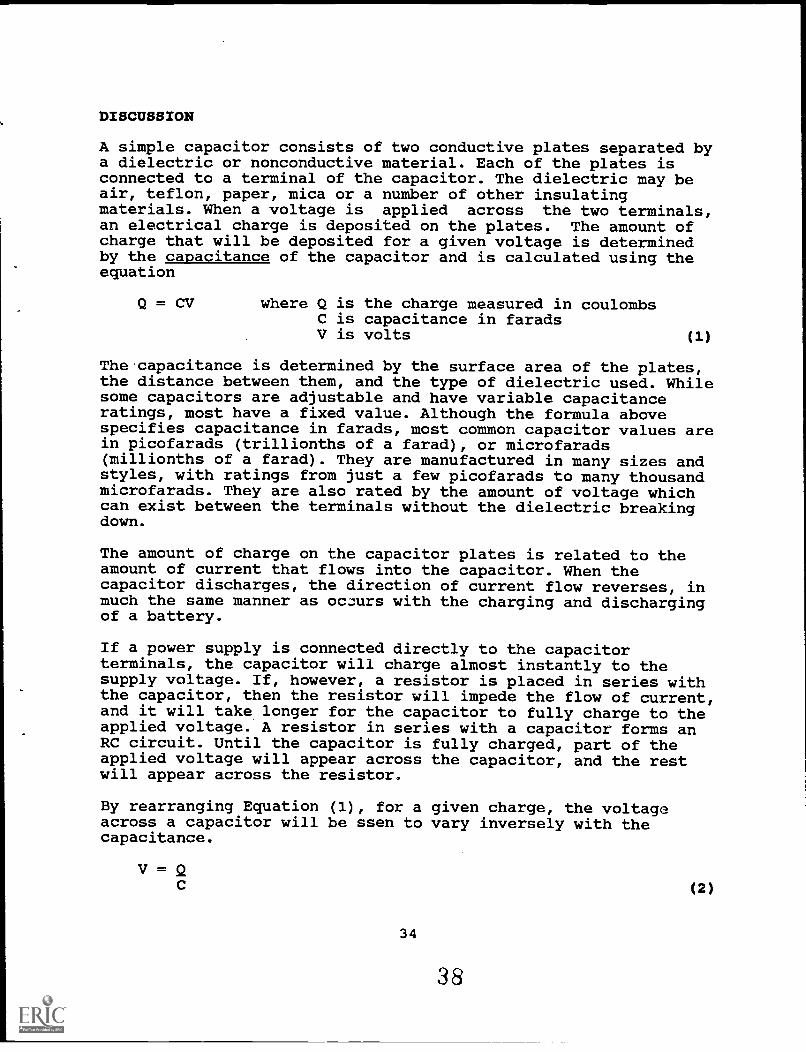
A simple capacitor consists of two conductive plates separated bya dielectric or nonconductive material. Each of the plates isconnected to a terminal of the capacitor. The dielectric may beair, teflon, paper, mica or a number of other insulatingmaterials. When a voltage is applied across the two terminals,an electrical charge is deposited on the plates. The amount ofcharge that will be deposited for a given voltage is determinedby the capacitance of the capacitor and is calculated using theequation
Q = CV where Q is the charge measured in coulombsC is capacitance in faradsV is volts ( 1 )
The.capacitance is determined by the surface area of the plates,the distance between them, and the type of dielectric used. Whilesome capacitors are adjustable and have variable capacitanceratings, most have a fixed value. Although the formula abovespecifies capacitance in farads, most common capacitor values arein picofarads (trillionths of a farad), or microfarads(millionths of a farad). They are manufactured in many sizes andstyles, with ratings from just a few picofarads to many thousandmicrofarads. They are also rated by the amount of voltage whichcan exist between the terminals without the dielectric breakingdown.
The amount of charge on the capacitor plates is related to theamount of current that flows into the capacitor. When thecapacitor discharges, the direction of current flow reverses, inmuch the same manner as oczurs with the charging and dischargingof a battery.
If a power supply is connected directly to the capacitorterminals, the capacitor will charge almost instantly to thesupply voltage. If, however, a resistor is placed in series withthe capacitor, then the resistor will impede the flow of current,and it will take longer for the capacitor to fully charge to theapplied voltage. A resistor in series with a capacitor forms anRC circuit. Until the capacitor is fully charged, part of theapplied voltage will appear across the capacitor, and the restwill appear across the resistor.
By rearranging Equation (1), for a given charge, the voltageacross a capacitor will be ssen to vary inversely with thecapacitance.
V = Q(2)
34
38
Therefore, if we know the charge on a capacitor and we know itscapacitance value, we can calculate the voltage across it. Thus,the voltage across a capacitor in an RC circuit can be determinedif we know the voltage applied to the circuit, the value of theresistor, the value of the capacitor, and the length of time thatthe capacitor has been charging through the resistor. The nextequation summarizes these relationships:
e-t/n) v = voltage across the capacitorE = applied voltagee = natural logarithmt = charging time in secondsR = series resistance in ohmsC = capacitance in farads
(3)
The exponential function (e-tnc) is important here. Note that whent= 0, the value of the function is 1. When this value issubstituted back into Equation (3), the voltage (v) across thecapacitor is zero.
v = E(1 - 1)= E(0)= 0
This makes sense since t = 0 at the instant that the supplyvoltage is first applied to the circuit and therefore no chargingtime has elapsed.
At the other extreme, the voltage (v) across the capacitor canequal the supply voltage (E) only when the exponential functionhas the value zero:
v = E(1 - 0)= E(1)= E
But for what value of (t) does the exponential function have avalue of zero ?
e -tfltc = 0 (4a)
1tCte
R)
- 0 (4b)
1
eVK 0 , but division by zero is undefined. (4c)
35
39
Although the solution to Equation (4c) is undefined, note inEquation (4b) that as (t) increases, the exponential functiontmce increases, therefore, its reciprocal decreases. As (t)
approaches infinity, the exponential function approachesinfinity, and its reciprocal does indeed approach zero. Thus, wecan conclude that as time passes, the voltage (v) across thecapacitor approaches the supply voltage but in theory, neverexactly reaches it.
Since the resistance and capacitance values also affect the timerequired to charge the capacitor, it is convenient to think ofthe product (RC) as being a time constant. When (t) equals (RC),in seconds, we say that one time constant has elapsed. When (t)equals two times (RC), we say that two time constants haveelapsed, and so forth. Note that in Eq.(4b), the base (e) israised to the power (t/RC). Consider the following values forthis equation:
is confirmed; as (t) increases, Equation (4b)Now, let's plug the above results back into
v = E (1 e-tnc)
Thenwhen t = RC
t = 2(RC)t = 3(RC)t = 4(RC)t = 5(RC)t = 6(RC)
v =v =V =v =v =v =
0.632(E)0.865(E)0.950(E)0.982(E)0.993(E)0.998(E)
or 63.2% of Eor 86.5% of Eor 95.0% of Eor 98.2% of Eor 99.3% of Eor 99.8% of E
We see that (v) is in fact approaching (E).
Note also that the time required to fully charge is independentof the value of (E). In practice, it is convenient to say thatthe capacitor is fully charged after 5 time constants, becausethe voltage across the capacitor (v) has reached more than 99% ofthe applied voltage (E). This generalization simplifies thecomputation of charging time for any RC circuit.
36
40
Example
How long does it take to fully charge a 10-microfarad capacitorthrough a 1000-ohm resistor?
Solution
The time constant for the RC circuit is (R * C) or
1000 ohms * 10 * 10-6 microfarads, which is 10 * 10-3
or
10 milliseconds.
The time required to fully charge is 5 time constants, or 50milliseconds.
37
41
Laboratory
EQUIPMENT
5300-microfarad capacitor with a rating of 12 V. or greater15000-microfarad capacitor with a rating of 12 V. or greater1000-ohm resistor12-V. lamp [].00-milliamp (1.2-watt) or smaller]Two switches (pushbutton, toggle, or slide)Voltmeter12-V. DC power supplyTimer or watch with minutes and seconds indicator
Optional:
The accuracy of the results in this lab depends on theaccuracy of the capacitor and resistor values. The actual valueof capacitors may differ by as much as 20% above or below therated capacitance. Resistors may vary by as much as 10%. If theactual values of these components is not known, then it may bedesirable to obtain a capacitor tester and an ohmmeter.Calculations should be done using the actual measured values.Otherwise, evaluation of the numerical results must take intoaccount possible errors due to differences between rated andactual values.
* Capacitors of the type required in this lab are* polarized. This means the terminals are* marked for proper connection to the positive and* negative leads of the power supply. Reversing the ** terminals will result in improper readings and* MAY RESULT IN A VIOLENT RUPTURE OF THE CAPACITOR 1 *
1. Construct the circuit shown in Figure 1 below, being carefulto observe the polarity of the capacitor. Make certain thatthe switch is in the OFF position and that the power supplyis also OFF.
0
12 VDC
1000 ohms"AC
5300uF @Voltmeter
2. Calculate the time constant (RC) for the circuit. Fill inall but the last column of the data table below.
# time time in percent capacitor voltage measuredconstants seconds charge voltage
(R * C)
1 63%
2 87%
3 95%
4 98%
5 99%
3. With the switch open, turn on the power supply. The voltageacross the capacitor should read zero because there is nopath for charging current.
4. Close the switch and record the voltage across the capacitorafter 1, 2, 3, 4 and 5 time constants in the last column ofthe data table.
5. Compare your observations with the expected readings.
39
4 3
6. Repeat steps 1 through 5, substituting the 15000-microfaradcapacitor for the 5300-microfarad.
# time time inconstants seconds
(R * C)
percent capacitor voltage measuredcharge voltage
(% * E)
1 63%
2 87%
3 95%
4 98%
5 99%
PART II
1. After making certain that both switches and the power supplyare turned off, construct the circuit below.
SWITCH #1
0
12 VDC 5300uF
SWITCH #2
12 V
2. Close switch #1. Note that the capacitor is immediatelycharged to 12 volts.
3. Open switch #1 and immediately close switch #2. The lampshould light briefly as the energy stored in the capacitor isdischarged. Note that the voltage across the capacitor hasdropped to zero.
4. Repeat steps 1 through 3, substituting the 15000-microfaradcapacitor for the 5300-microfarad.
5. Compare the brightness of the lamp for the two differentcapacitor values. It should be apparent that the higher valuecapacitor stores more energy.
40
4 4
UNIT IV
MEASURING THERMAL POWER
41
45
MEASURING THERMAL POWER Lab 6T1
LAB OBJECTIVE
When you've finished this lab, you should be able to explain theeffect of thermal power input on a system's mechanical poweroutput.
LEARNING PATH
1. Preview the lab. This will give you an idea of what's ahead.
2. Read the lab and pay particular attention to the labobjectives.
3. Do the lab, "Measuring Thermal Power."
MAIN IDEA
* Turbines are used to convert thermal power into mechanicalpower.
42
46
TEACHING PATH - CLASS Ll
RESOURCE MATERIALS. --
Lab 6T1: "Measuring Thermal Power"
CLASS GOALS
See OBJECTIVES for Lab 6T1
CLASS ACTIVITIES
(Set up the lab and run through the procedures before thestudents try the lab. You'll be able to anticipate studentdifficulties.)
1. Preview the lab for the students and explain what the lab isabout. Show students the equipment and tell them what theyare to accomplish.
2. Have the students follow the procedures outlined in the labinstructions and encourage students to read the procedurescarefully. (Reading detailed procedures and followinginstructions are important parts of a technician'straining.)
3. Monitor student progress and provide help as needed.
43
CONSTRUCTING THE TURBINE
The turbine can be built using the attached drawing "TURBINEASSEMBLY DRAWING". The turbine diffuser can be built using theattached drawing "TURBINE DIFFUSER DRAWING". Students in theschool's shop classes can make the turbine using aviation snips.The diffuser will require advanced sheet metal working skills andskills in Gas Tungsten Arc Welding (GTAW or T1G).
Make photocopies of the "TURBINE TOP VIEW" and use the copy for apattern by which to cut the sheet metal. None of the dimensionsare critical. [CAUTION: When working with sheet metals, becareful not to get cut by the sharp edges.]
To further study the operation of turbines, try bending theblades on several turbines to different angles to show the effectof blade angle on thermal power efficiency.
Any "turbine-like" device will work as long as it is not subjectto deterioration by heat. [NOTE: Children's pinwheels willconstitute a fire hazard.]
If a Bunsen burner is not available, consider substitutions suchas: hurricane lamps or electric lamps (globe having a 1.5 to 2inch opening in the top.) [CAUTION: Follow standard safetyprocedures when working with a Bunsen burner.]
4in
.
3.5
in,
1- 1
.5in
,'O
w*
ALU
MIN
UM
BLO
CK
1/2
IN D
.D. x
1/2
IN
#441
444.
141
0:44
:34,
44'4
0:44
4+ "
el)
4**
4**
" *
e s
4**
4**
M.*
4**
4**
""
4*, e
ees
41 4
ves
$4.
Tte
re.0
40:3
10.4
4,4.
,;
i4.s
....4
., 4.
44, 4
*. 4
ves
esee
4+44
+4.
".4.
1W 4
** 0
+ 4
1 4*
44.
_frz
z :-
'It+
++
4.41
4.4*
*
titili
4.4.
4e
' - -
*4.4
4Itt*
-41.
5.
%V
OL.
_v.
'__ V
W4F
4331
4.1
4.4.
4.4
444
$$
04 0
"4 11
14:f!
el+
14.4
7
*40+
40+
0_L
1..."
14.4
+:4
.4.4
4:44
.,A
+4.
4.4$
4+
t.4.
4.4.
.-4.
-.4
3.-4
.,
..4.,
4.4.
,4.
4.1.
44+
+,4
414$
040+
+4"
4"4.
7W
ELD
TO
DIF
US
ER
.44;
$1.0
4044
1.04
4+44
.44t
4.1.
47N
EC
K
104.
1440
4M$4
4.1?
:VIN
ST
ALL
1/4
IN P
NE
UM
AT
ICC
OM
PR
ES
SIO
N F
ITT
ING
(5,
S.)
DIF
FU
SE
R S
IDE
VIE
W
DR
ILL
& T
AP
/ 4 IN
F.N
.P.T
.
NO
TE
S1
1. M
ater
ial 1
6 ga
uge
alum
inum
a W
eld
and
grin
d A
LL s
eam
s3.
ALL
exp
osed
edg
es to
be
fold
ed, w
elde
d an
d gr
ound
to e
limin
ate
cutti
ng h
azar
ds
4 9
DIF
FU
SE
R T
OP
VIE
W
Tut
;'bin
e D
iffus
erD
raw
ing
drawn' J.T. Brown
date! 2/9/90
scale! FULL
50
Loos
ely
atta
ch-t
urbi
ne to
rod
with
1/3
2 in
.pi
n.
ALU
MIN
UM
RO
D
0.5
in. D
IAM
ET
ER
5.5
in. L
ON
G AS
SE
MB
LED
TU
RB
INE
Cut
turb
ine
from
20 g
auge
she
et o
f'A
LUM
INU
MT
UR
BIN
E T
OP
VIE
W
Tw
ist b
lade
end
s15
to 3
0 de
gree
s.(T
ypic
al o
f 8)
TU
RB
INE
SID
E V
IEW
Tur
bine
Ass
embl
y D
raw
ing
draw
n' J
.T. B
row
nda
te' 1
/12/
90sc
ale'
FU
LL
DISCUSSION
A gas turbine is a device which extracts the thermal powerfrom a gas stream and converts it into mechanical power.Gas turbines are used in industry to generate emergencyelectrical power. A gas turbine is the heart of the engines usedto power jet aircraft.
HOW DOES A GAS TURBINE WORK?
Figure 1 shows the turbine used in a gas turbine. The turbineconsists of a series of blades placed around the periphery of awheel. The turbine wheel is attached to a shaft which turns withit.
TURBINEBLADES
TURBINEWHEEL
TURBINESHAFT
Figure 1 Turbine blades and wheel
Figure 2 shows the operation of a gas turbine. Hot gases passingover the turbine blades transfer power to the blades. The bladesthen move because of the power they receive. Since the blades areattached to the turbine wheel, they can only move so as to turnthe wheel and its shaft. The rotating shaft then has mechanicalpower because of the thermal power imparted to it by the hotgases passing over the turbine blades.
COMBUSTIONCHAMBERS
HOTGASES
TURBINE_iSHAFT
Li
TURBINEBLADES
Figure 2 Gas turbine operation
47
53
Figure 3 shows a single turbine blade with the force imparted toit by the hot gases passing over the blade.
Figure 3 Forces on a turbine blade
Since the force of the blades is at a distance from the center ofthe turbine shaft, the gases produce a torque on the shaft. Theturbine shaft will turn at a certain speed so that the powerimparted to the shaft by the hot gases can be determined from theformula
POWER = TORQUE * SPEED
-or-
P = T * S
where P = power imparted to the shaft in watts,
(1)
S = speed of the turbine blades in REVOLUTIONS PER SECONDand
T = torque produced by the hot gas on ALL of the turbineblades in newton-meters or
T = F * D (2)
where F = force produced by the hot gases on ALL of the turbineblades in newtons and
D = distance this force acts from the center of the turbineshaft in meters.
48
5 4
APPLICATIONS FOR GAS TURBINES
Figure 4 shows the internal construction of a jet engine.
COMPRESSORBLADES
COMBUSTIONCHAMBERS
HOTGASES
TURBINESHAFT
TURBINEBLADES
Figure 4 Internal construction of a jet engine
In the jet engine, hot gases turn the turbines, which then turncompressors, which provide high pressure air, which is used toburn the fuel to produce the hot gases to drive the turbines. Insome jet engines, other turbines turn fans which push more airthrough the engine and outside of the combustion chamber toincrease the thrust (force of the exhaust gases), which thenmoves the airplane.
FANBLADES
COMPRESSORBLADES
COMBUSTIONCHAMBERS
TURBINESHAFT
TURBINEBLADES
Figure 5 Fans added to a jet engine
The next time you hear a jet airplane fly overhead, remember thatthermal power is the source of power which causes the airplane tofly.
49
55
Laboratory
EQUIPMENT
Bunsen BurnerRing StandClampsRing ClampTurbineTurbine DiffuserThermocouple and multimeterStop watch or clock with a second hand
PROCEDURES
1. Mount the turbine and diffuser on the ring stand above theBunsen burner.
2. Insert the thermocouple into the compression fitting on thediffuser and tighten the nut enough to grip the thermocouple.
3. Light the Bunsen burner and turn it to its lowest intensityflame. [CAUTION: Do not allow the flame to impinge on theturbine/diffuser to prevent damage to the turbine/diffuser]
4. Count the number of turbine revolutions per minute (RPM) andrecord this value in Data Table 1.
5. Measure the Gas Inlet Temperature from the thermocouple andrecord this value in Data Table 1.
6. Turn the Bunsen burner to a slightly higher flame intensityand record the temperature/RPM readings in Data Table 1.
7. Repeat Step 4 until the Bunsen burner has been turned to itsmaximum flame intensity. (Try to obtain 10 test points)
S. Turn the Bunsen burner off, and allow the turbine to coolbefore disassembling the apparatus.
50
56
DATA TABLE 1
Gas Inlet Temperature Turbine RPM Reading
WRIi12-IIP
1. The turbine has a frictional resistance which the thermalpower must overcome. This resistance means that the thermalpower (P) must impart a torque (T) to the turbine to cause itto rotate at a certain speed (S). The formula which shows thiseffect is
P = T * S (3)
2. Let's assume that the torque required to turn our turbine isconstant. (This is approximately correct at the relativelyslow speeds obtained in this lab exercise). Then, the ratioof the power developed at one test point to the powerdeveloped at another test point is f
P = S1 iP2 S2
where P1 = Power developed at Test Point 1S
1= Turbine speed at Test Point 1
P2 = Power developed at Test Point 2S2= Turbine speed at Test Point 2.
51
5 7
(4)
3. Now, by setting the lowest Bunsen burner flame intensity astest point 2, we can calculate the power ratio between theother test points by calculating the speed ratios betweenthose same test points.
4. Using the turbine speed at the lowest Bunsen burner flameintensity as S2, calculate the power ratios for all of thetest points and tabulate this data in Data Table 2.
DATA TABLE 2
POINT S1 (RPM) S2 (RPM) P1/P2 = Si/S2
1
2
3
4
5
6
7
8
9
10
5. How does the thermal power imparted to the turbine affect thespeed of the turbine? What can you infer about the mechanicalpower output at the turbine shaft? How is thermal powerrelated to Gas Inlet Temperature?