89
EDAConnect-Dashboard User’s Guide Version 3.5.0 Oracle Part Number: E73438-01
EDAConnect-Dashboard User’s Guide
Version 3.5.0
Oracle Part Number: E73438-01
2
Perception Software Proprietary Information
Perception Software Company Confidential Copyright © 2016 Perception Software
All Rights Reserved This document contains information that is confidential and proprietary to Perception Software, Inc. This information is supplied for identification, maintenance, evaluation, engineering, and inspection purposes only, and shall not be duplicated or disclosed without prior written permission from an authorized representative of Perception Software. This document and any other confidential information shall not be released to any third party without a valid non-disclosure agreement signed by the third party and an authorized Perception Software representative. In accepting this document, the recipient agrees to make every reasonable effort to prevent the unauthorized use of this information. EDAConnect-Dashboard Version: 3.5.0 March, 2016
3
Perception Software Proprietary Information
Contents
............................................................................................................................................................................
Preface.............................................................................................................................. 7
EDAConnect-Dashboard User’s Guide Overview ....................................................................... 7
Font Conventions ....................................................................................................................... 7
Perception Software Technical Support ...................................................................................... 7
EDAConnect Dashboard Overview ................................................................................ 9
Introduction ................................................................................................................................. 9
How the EDAConnect Dashboard Works.................................................................................. 10
Dashboard Interface ...................................................................................................... 11
Launching the EDAConnect Dashboard ................................................................................... 11
► To launch the Dashboard from Windows .............................................................. 11
► To launch the Dashboard from Altium Designer ................................................... 11
► To launch the Dashboard from DxDesigner .......................................................... 12
► To launch the Dashboard from Orcad ................................................................... 12
Dashboard Organization ........................................................................................................... 13
► Modules ............................................................................................................... 14
► Shortcuts .............................................................................................................. 14
► PLM Login ............................................................................................................ 14
► Project Editor ........................................................................................................ 16
Defining Preferences ................................................................................................................ 20
► EDAConnect Workbench Preferences .................................................................. 20
► Appearance Preferences ...................................................................................... 20
► BOM Global Settings ............................................................................................ 22
► Custom Shortcuts ................................................................................................. 22
► ECAD ITC Settings ............................................................................................... 23
► File Checkout Preferences ................................................................................... 23
► General Settings................................................................................................... 24
► Logging Preferences ............................................................................................ 24
► Perspectives Preferences ..................................................................................... 25
► Template Settings ................................................................................................ 25
► Web Browser Preference ..................................................................................... 26
► Default Browser URL ............................................................................................ 27
EDAConnect-Dashboard Error Messages ................................................................................ 28
EDAConnect Task Based Modules .............................................................................. 30
Checkin of Project Data to PLM ................................................................................................ 30
► Checkin Main Page .............................................................................................. 30
► Design Structure................................................................................................... 31
► Change Orders Page ........................................................................................... 33
► BOM Page ............................................................................................................ 36
► Files Page ............................................................................................................ 39
4
Perception Software Proprietary Information
► Results Summary Page ........................................................................................ 42
Checkout of Project Data from PLM.......................................................................................... 45
► Checkout Options ................................................................................................. 45
► Update current project – Update Project ............................................................... 46
► Update current project – Change Orders Page ..................................................... 46
► Update current project - Files Page ...................................................................... 47
► Checkout New - Checkout Page ........................................................................... 48
Getting File Attachments from PLM .......................................................................................... 49
Agile Part Creation ................................................................................................................... 50
► Part Numbers and Change Requests ................................................................... 50
► Agile Part Attributes .............................................................................................. 52
► Manufacturer Part File Attachments ..................................................................... 53
► Results ................................................................................................................. 54
Create Design Numbers ........................................................................................................... 55
► Main Page – Project Name and Location ............................................................. 56
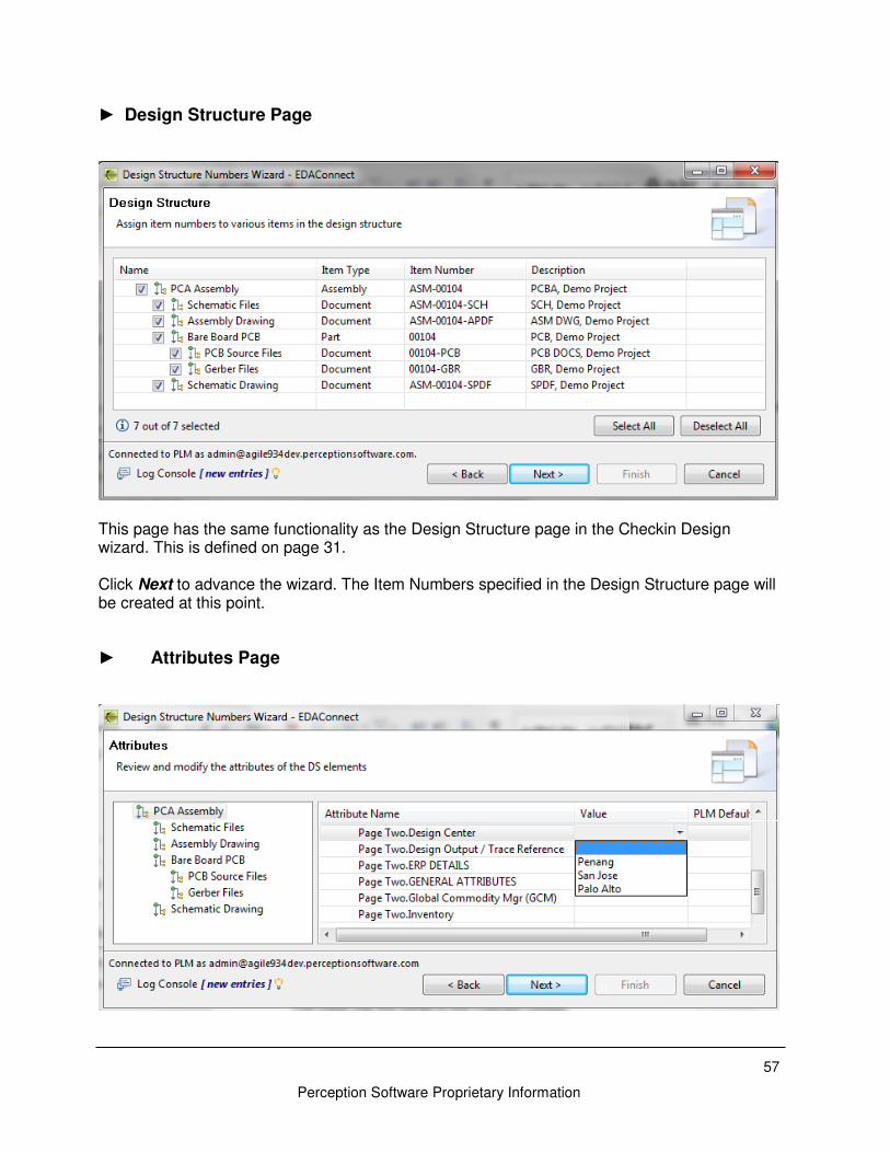
► Design Structure Page ......................................................................................... 57
► Attributes Page ..................................................................................................... 57
► Results Page ........................................................................................................ 58
EDAConnect Templates ................................................................................................ 59
Introduction ............................................................................................................................... 59
Embedded Scripts ....................................................................... Error! Bookmark not defined. Using Design and Environment Variables ................................................................................. 63
Using Script Variables .............................................................................................................. 63
► To add a variable to the Scripts Variable table ..................................................... 64
► To delete a variable from the Script Variables table .............................................. 64
Global Scripts ........................................................................................................................... 64
Embedded Scripts .................................................................................................................... 66
Creating and Editing Templates ................................................................................................ 68
► To create a EDAConnect-Dashboard template file via the Template Editor .......... 68
Attribute Mappings .................................................................................................................... 69
► To specify global ECAD to PLM attribute mappings ............................................. 69
Change Templates ................................................................................................................... 70
To specify a Change Template .................................................................................... 70
Design Structure ....................................................................................................................... 72
To specify a Design Structure ...................................................................................... 72
Adding a Child to a Design Structure Element.............................................................. 73
BOM Sources ........................................................................................................................... 74
► To specify a BOM Source ..................................................................................... 74
CSV BOM Source ............................................................................................................ 75
► To specify a CSV BOM source ............................................................................. 75
Tool BOM Source ............................................................................................................ 76
► To specify a Tool BOM source ............................................................................. 76
Script BOM Source .......................................................................................................... 77
► To specify a Script BOM source ........................................................................... 77
File Sources ............................................................................................................................. 78
File Filters ........................................................................................................................ 78
► To add a File Filter to a File Source ...................................................................... 79
► To delete a File Filter from a File Source .............................................................. 79
► To specify a File Source ....................................................................................... 80
5
Perception Software Proprietary Information
CSV File Source .............................................................................................................. 80
► To specify a CSV File Source ............................................................................... 80
Directory File Source ....................................................................................................... 81
► To specify a Directory File Source ........................................................................ 81
Tool File Source ............................................................................................................... 83
► To specify a Tool File Source ............................................................................... 83
Script File Source............................................................................................................. 84
► To specify a Script File Source ............................................................................. 84
Event Handlers ......................................................................................................................... 85
► To specify an Event Handler ................................................................................ 85
► To add an event trigger to a script ........................................................................ 86
► To delete an event trigger from a script ................................................................ 88
Problem Reporting ........................................................................................................ 88
Information Gathering ............................................................................................................... 88
Version Number and Build ID ................................................................................................... 89
► To obtain the EDAConnect-Dashboard Version and Build ID ............................... 89
EDAConnect-Dashboard Error Logs ......................................................................................... 89

Preface 7
Perception Software Proprietary Information
Preface
EDAConnect-Dashboard User’s Guide Overview This manual provides instructions for using EDAConnect-Dashboard and is organized into the following sections:
• EDAConnect Dashboard Overview — Summarizes the features of EDAConnect and how it is used within the PLM process.
• Dashboard Interface — describes the function and user interface for the EDAConnect Dashboard.
• EDAConnect Task Based Modules — describes each of the EDAConnect Dashboard modules.
• EDAConnect Templates — Provides instructions for creating EDAConnect templates.
• Problem Reporting — describes how to report an EDAConnect issue and obtain technical support.
Font Conventions In this guide, the following font conventions are used:
• Links, buttons, menus, and icons that are clicked appear in Bold Face Type.
• Items to select in drop-down menus or navigation trees are bold with “→” between entries.
• Dialog box “field names” are in quotes.
• Window and field names are in Initial Capitals.
• Cross references to sections and other chapters appear as underlined text.
• Information to be provided or entered by the user appear in <italicized text> between angle brackets.
• References to other Perception Software documentation appear in italicized text.
Perception Software Technical Support For EDAConnect PCB issues, please contact us via email at:

EDAConnect Dashboard Overview 9
Perception Software Proprietary Information
EDAConnect Dashboard Overview
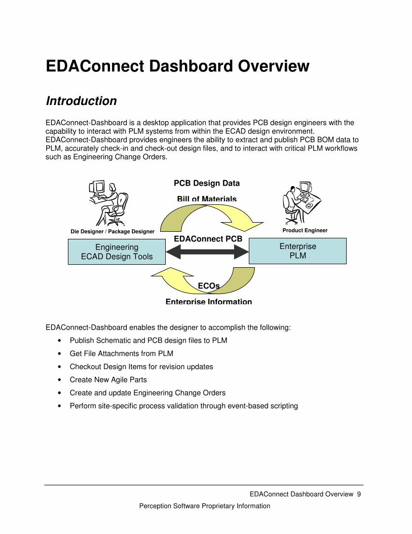
Introduction EDAConnect-Dashboard is a desktop application that provides PCB design engineers with the capability to interact with PLM systems from within the ECAD design environment. EDAConnect-Dashboard provides engineers the ability to extract and publish PCB BOM data to PLM, accurately check-in and check-out design files, and to interact with critical PLM workflows such as Engineering Change Orders. EDAConnect-Dashboard enables the designer to accomplish the following:
• Publish Schematic and PCB design files to PLM
• Get File Attachments from PLM
• Checkout Design Items for revision updates
• Create New Agile Parts
• Create and update Engineering Change Orders
• Perform site-specific process validation through event-based scripting
Engineering ECAD Design Tools
Product Engineer Die Designer / Package Designer
Enterprise PLM
PCB Design Data
Bill of Materials
ECOs
Enterprise Information
EDAConnect PCB
10
Perception Software Proprietary Information
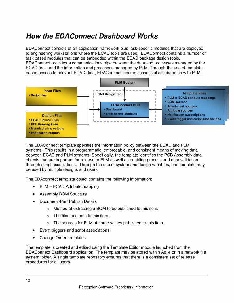
How the EDAConnect Dashboard Works EDAConnect consists of an application framework plus task-specific modules that are deployed to engineering workstations where the ECAD tools are used. EDAConnect contains a number of task based modules that can be embedded within the ECAD package design tools. EDAConnect provides a communications pipe between the data and processes managed by the ECAD tools and the information and processes managed by PLM. Through the use of template-based access to relevant ECAD data, EDAConnect insures successful collaboration with PLM. The EDAConnect template specifies the information policy between the ECAD and PLM systems. This results in a programmatic, enforceable, and consistent means of moving data between ECAD and PLM systems. Specifically, the template identifies the PCB Assembly data objects that are important for release to PLM as well as enabling process and data validation through script associations. Through the use of system and design variables, one template may be used by multiple designs and users. The EDAconnect template object contains the following information:
• PLM – ECAD Attribute mapping
• Assembly BOM Structure
• Document/Part Publish Details
o Method of extracting a BOM to be published to this item.
o The files to attach to this item.
o The sources for PLM attribute values published to this item.
• Event triggers and script associations
• Change Order templates The template is created and edited using the Template Editor module launched from the EDAConnect Dashboard application. The template may be stored within Agile or in a network file system folder. A single template repository ensures that there is a consistent set of release procedures for all users.
Template Files
• PLM to ECAD attribute mappings
• BOM sources
• Attachment sources
• Attribute sources
• Notification subscriptions
• Event trigger and script associations
• ECO templates
EDAConnect PCB
• Dashboard
• Task Based Modules
PLM System
Input Files
• Script files
Design Files
• ECAD Source Files
• PDF Drawing Files
• Manufacturing outputs
• Fabrication outputs
ECAD Design Tool
11
Perception Software Proprietary Information
Dashboard Interface The EDAConnect interface has been designed to be intuitive and easy to use. This section describes the main features of the EDAConnect Dashboard interface including preferences that influence the task based modules that are described in the subsequent chapters of this manual.
Launching the EDAConnect Dashboard EDAConnect modules and shortcuts utilize an Eclipse-based GUI and are accessed via the EDAConnect Dashboard. The Dashboard may be accessed in the following ways:
• Windows batch file
• Altium Designer menu
• DxDesigner menu
• Orcad Menu
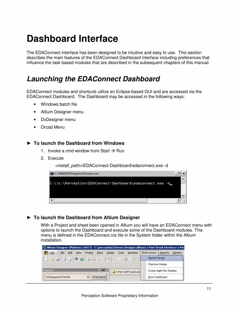
► To launch the Dashboard from Windows
1. Invoke a cmd window from Start � Run
2. Execute
<install_path>\EDAConnect-Dashboard\edaconnect.exe -d
► To launch the Dashboard from Altium Designer
With a Project and sheet been opened in Altium you will have an EDAConnect menu with options to launch the Dashboard and execute some of the Dashboard modules. This menu is defined in the EDAConnect.rcs file in the System folder within the Altium installation.
12
Perception Software Proprietary Information
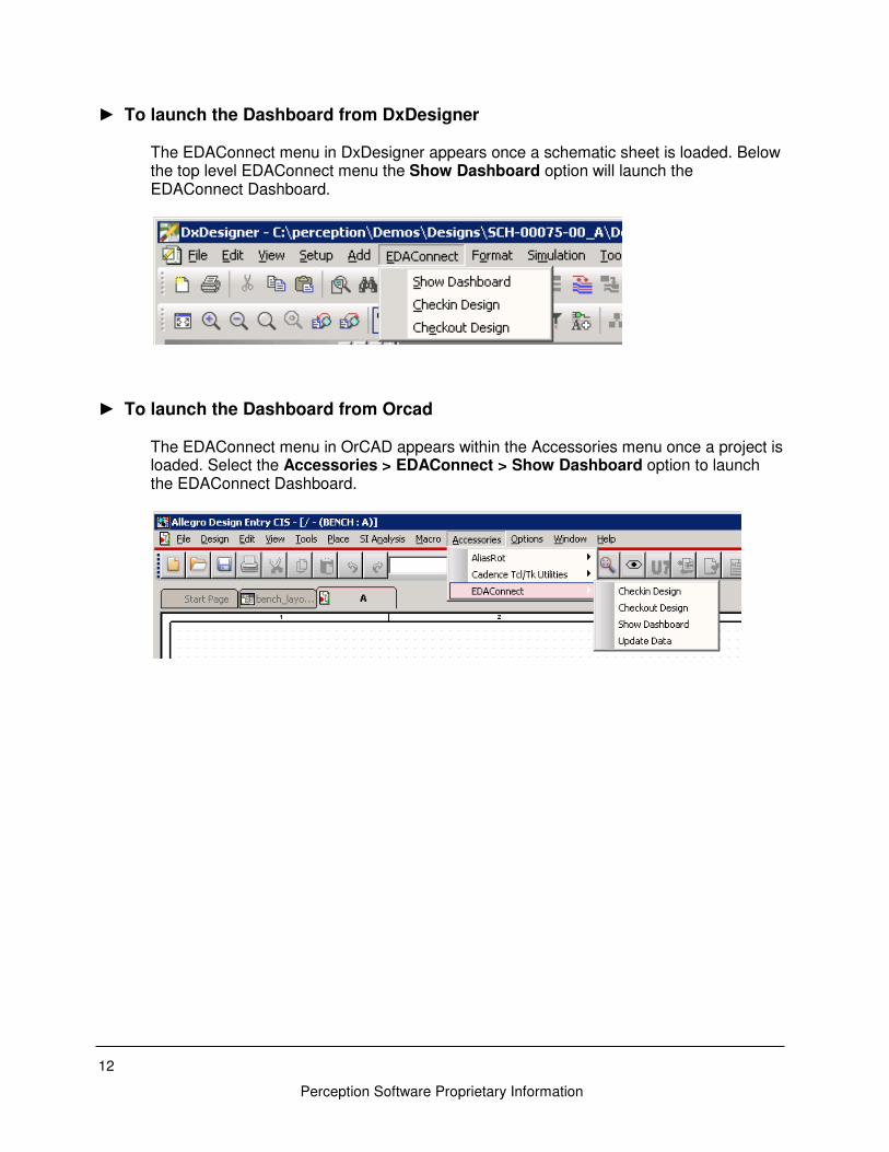
► To launch the Dashboard from DxDesigner
The EDAConnect menu in DxDesigner appears once a schematic sheet is loaded. Below the top level EDAConnect menu the Show Dashboard option will launch the EDAConnect Dashboard.
► To launch the Dashboard from Orcad
The EDAConnect menu in OrCAD appears within the Accessories menu once a project is loaded. Select the Accessories > EDAConnect > Show Dashboard option to launch the EDAConnect Dashboard.
13
Perception Software Proprietary Information
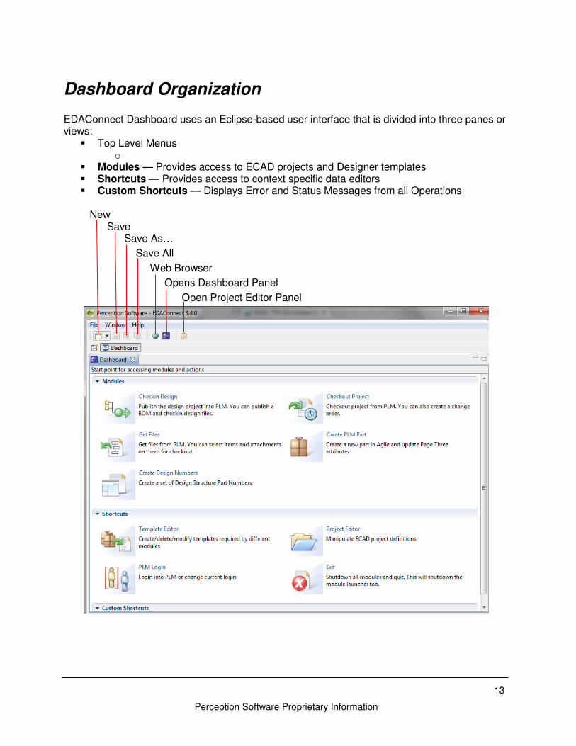
Dashboard Organization EDAConnect Dashboard uses an Eclipse-based user interface that is divided into three panes or views:
� Top Level Menus o
� Modules — Provides access to ECAD projects and Designer templates � Shortcuts — Provides access to context specific data editors � Custom Shortcuts — Displays Error and Status Messages from all Operations
New Save Save As…
Save All
Web Browser
Opens Dashboard Panel
Open Project Editor Panel
14
Perception Software Proprietary Information
The EDAConnect Dashboard is divided into three sections:
• Modules for process based actions
• Shortcuts for process-independent actions
• Custom Shortcuts for launching internal tools
► Modules Flow-specific Modules include:
• Checkin Design – Publish the design project into PLM.
• Checkout Project – Checkout project from PLM.
• Get Files – Get file attachments from PLM.
• Create PLM Part – Creates a new Agile Part with link to Manufacturer part
• Create Design Numbers – Create new Agile Items for PCBA and document parts
These modules are described in detail in EDAConnect Task on page31.
► Shortcuts Flow-independent Shortcuts include:
• Template Editor – Creates and modifies Dashboard Templates
• PLM Login – Sets up PLM Login preferences
• Project Editor – Create and maintain Project definitions
• Exit – Closes all open modules and the edalauncher daemon
► PLM Login
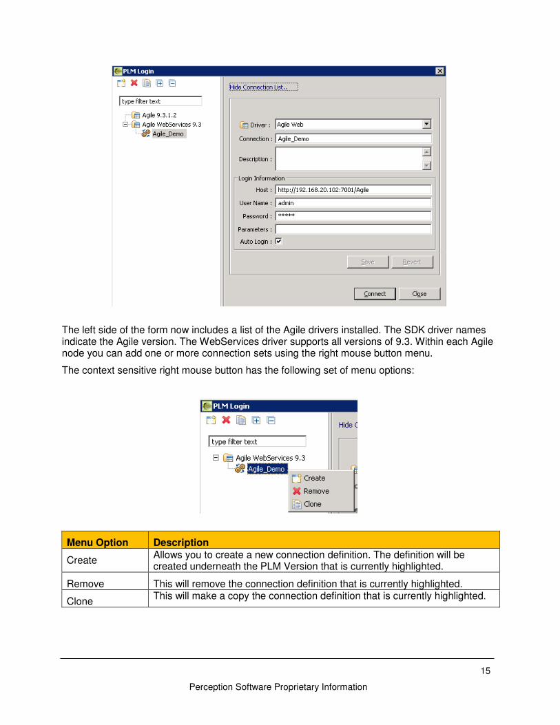
PLM Login is used to specify Agile login credentials and connect to an Agile instance. You can create and save multiple connections sets for the same Agile Version. If Auto Login is not enabled you will be prompted to log into PLM every time you invoke a new module. If Auto Login is enabled, then PLM login occurs automatically whenever a module is launched or closed, respectively. Passwords are encrypted and all connection definitions are saved to file: %HOMEPATH%\Application Data\EDAC\plmConnections.dat. The Parameters field is not used by the Agile driver and can be left blank when initially setting up the form.
15
Perception Software Proprietary Information
The left side of the form now includes a list of the Agile drivers installed. The SDK driver names indicate the Agile version. The WebServices driver supports all versions of 9.3. Within each Agile node you can add one or more connection sets using the right mouse button menu.
The context sensitive right mouse button has the following set of menu options:
Menu Option Description
Create Allows you to create a new connection definition. The definition will be created underneath the PLM Version that is currently highlighted.
Remove This will remove the connection definition that is currently highlighted.
Clone This will make a copy the connection definition that is currently highlighted.
16
Perception Software Proprietary Information
With a connection definition highlighted on the left you will get a list of the parameters for that connection on the right. Once these parameters have been set click Save to specify new or update existing parameters. Field Name Description Driver This is a pre-defined list and is based on the Agile drivers that you
have installed. Connection This name describes the connection definition for the user and will be
the name of the connection node displayed on the left. Description This is an optional description for the connection Host This is the path to the Agile instance (e.g. http://agile.server.com/Agile) User Name Agile user name Password Agile password Parameters Not used Auto Login If checked the user will automatically be logged in when the user
invokes any of the modules.
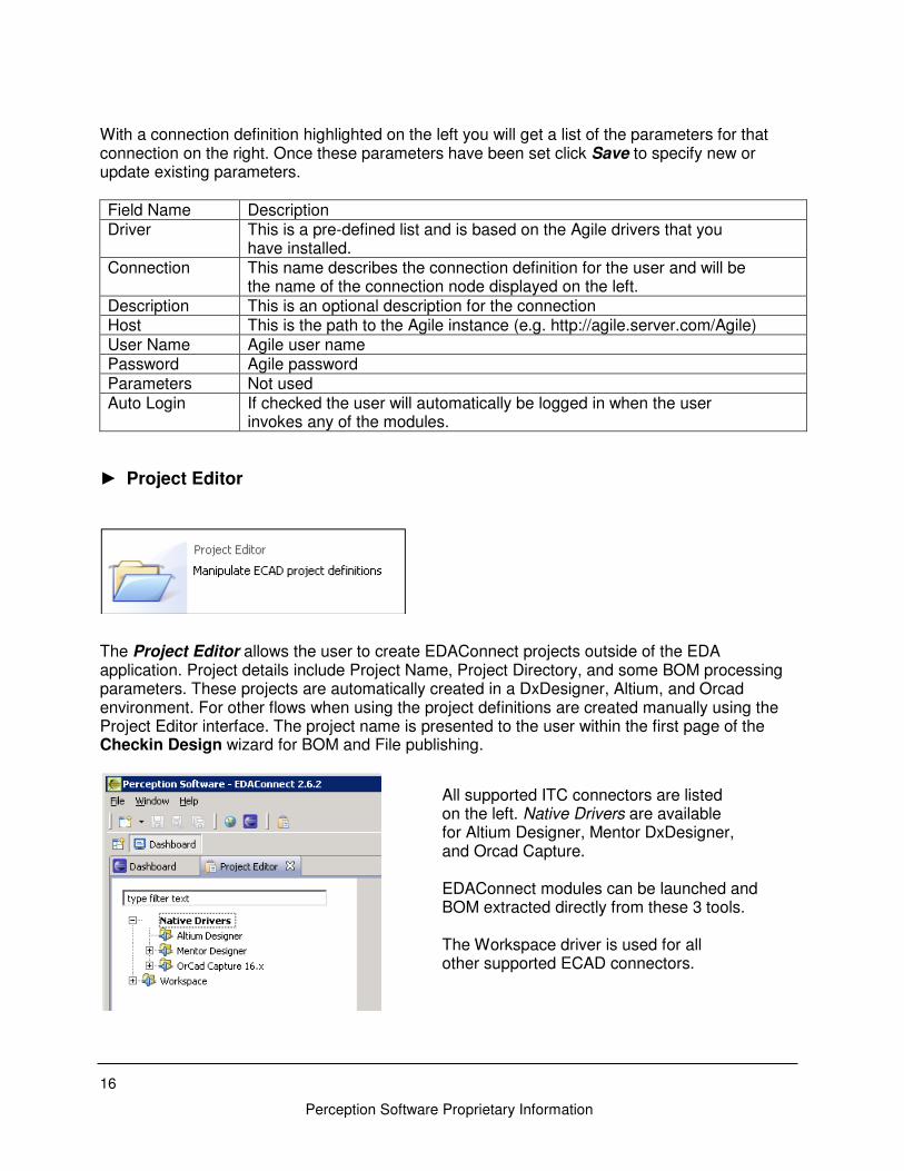
► Project Editor
The Project Editor allows the user to create EDAConnect projects outside of the EDA application. Project details include Project Name, Project Directory, and some BOM processing parameters. These projects are automatically created in a DxDesigner, Altium, and Orcad environment. For other flows when using the project definitions are created manually using the Project Editor interface. The project name is presented to the user within the first page of the Checkin Design wizard for BOM and File publishing.
All supported ITC connectors are listed on the left. Native Drivers are available for Altium Designer, Mentor DxDesigner, and Orcad Capture. EDAConnect modules can be launched and BOM extracted directly from these 3 tools. The Workspace driver is used for all other supported ECAD connectors.
17
Perception Software Proprietary Information
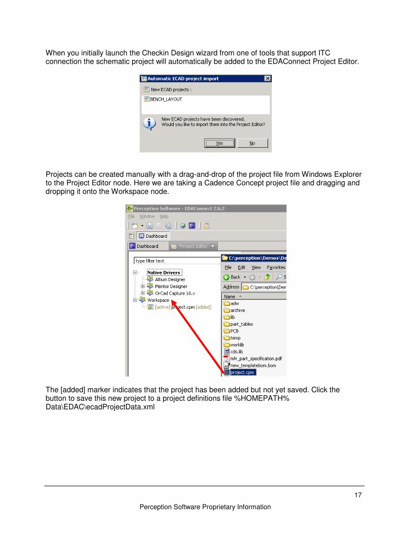
When you initially launch the Checkin Design wizard from one of tools that support ITC connection the schematic project will automatically be added to the EDAConnect Project Editor.
Projects can be created manually with a drag-and-drop of the project file from Windows Explorer to the Project Editor node. Here we are taking a Cadence Concept project file and dragging and dropping it onto the Workspace node.
The [added] marker indicates that the project has been added but not yet saved. Click the button to save this new project to a project definitions file %HOMEPATH% Data\EDAC\ecadProjectData.xml
18
Perception Software Proprietary Information
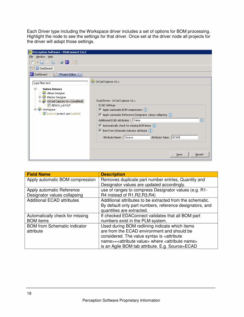
Each Driver type including the Workspace driver includes a set of options for BOM processing. Highlight the node to see the settings for that driver. Once set at the driver node all projects for the driver will adopt those settings.
Field Name Description Apply automatic BOM compression Removes duplicate part number entries, Quantity and
Designator values are updated accordingly. Apply automatic Reference Designator values collapsing
use of ranges to compress Designator values (e.g. R1- R4 instead of R1,R2,R3,R4)
Additional ECAD attributes Additional attributes to be extracted from the schematic. By default only part numbers, reference designators, and quantities are extracted.
Automatically check for missing BOM items
If checked EDAConnect validates that all BOM part numbers exist in the PLM system.
BOM from Schematic indicator attribute
Used during BOM redlining indicate which items are from the ECAD environment and should be considered. The value syntax is <attribute name>=<attribute value> where <attribute name> is an Agile BOM tab attribute. E.g. Source=ECAD
19
Perception Software Proprietary Information
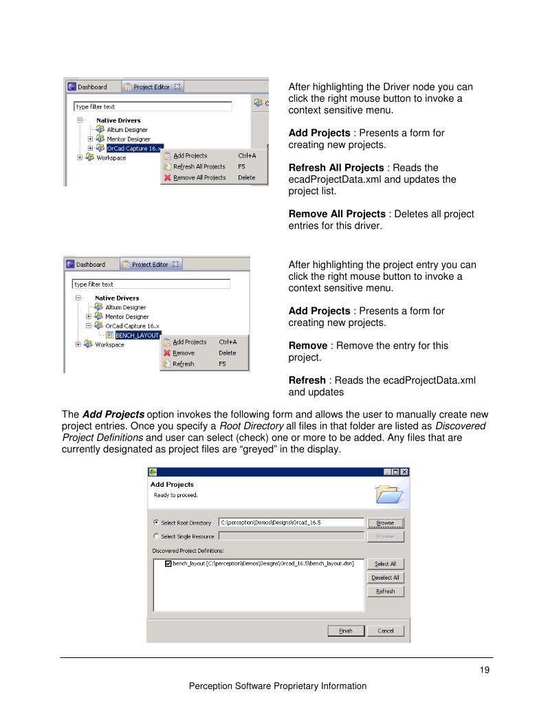
The Add Projects option invokes the following form and allows the user to manually create new project entries. Once you specify a Root Directory all files in that folder are listed as Discovered Project Definitions and user can select (check) one or more to be added. Any files that are currently designated as project files are “greyed” in the display.
After highlighting the Driver node you can click the right mouse button to invoke a context sensitive menu. Add Projects : Presents a form for creating new projects. Refresh All Projects : Reads the ecadProjectData.xml and updates the project list. Remove All Projects : Deletes all project entries for this driver.
After highlighting the project entry you can click the right mouse button to invoke a context sensitive menu. Add Projects : Presents a form for creating new projects. Remove : Remove the entry for this project. Refresh : Reads the ecadProjectData.xml and updates
20
Perception Software Proprietary Information
Process Note: The creation of a project with the Project Editor is required for integration with those ECAD tools that do not support the embedded EDAConnect menu. Any tools outside of Altium, DxDesigner, and Orcad required a project to be created manually using the Project Editor.
Defining Preferences
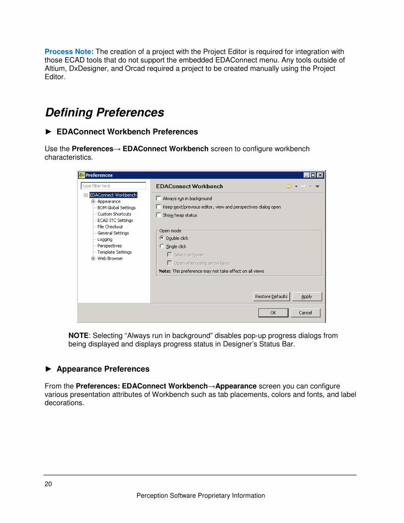
► EDAConnect Workbench Preferences Use the Preferences→ EDAConnect Workbench screen to configure workbench characteristics.
NOTE: Selecting “Always run in background” disables pop-up progress dialogs from being displayed and displays progress status in Designer’s Status Bar.
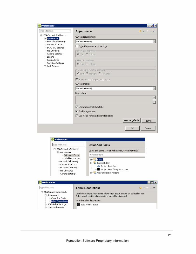
► Appearance Preferences From the Preferences: EDAConnect Workbench→Appearance screen you can configure various presentation attributes of Workbench such as tab placements, colors and fonts, and label decorations.
21
Perception Software Proprietary Information
22
Perception Software Proprietary Information
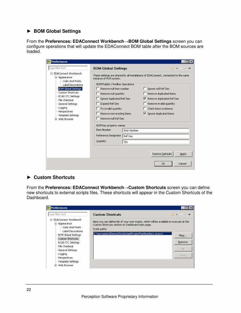
► BOM Global Settings From the Preferences: EDAConnect Workbench→BOM Global Settings screen you can configure operations that will update the EDAConnect BOM table after the BOM sources are loaded.
► Custom Shortcuts From the Preferences: EDAConnect Workbench→Custom Shortcuts screen you can define new shortcuts to external scripts files. These shortcuts will appear in the Custom Shortcuts of the Dashboard.

23
Perception Software Proprietary Information
► ECAD ITC Settings From the Preferences: EDAConnect Workbench→ECAD ITC Settings screen you can define the connector you are using.
► File Checkout Preferences From the Preferences: EDAConnect Workbench→File Checkout screen you can define options for getting data from the Checkout Project Get Attachments modules.
You can use system variables or project variables (e.g. PROJECTDIR) when specifying the Default checkout directory. Options for the Default overwrite behavior are Prompt, Overwrite, or Skip.
24
Perception Software Proprietary Information
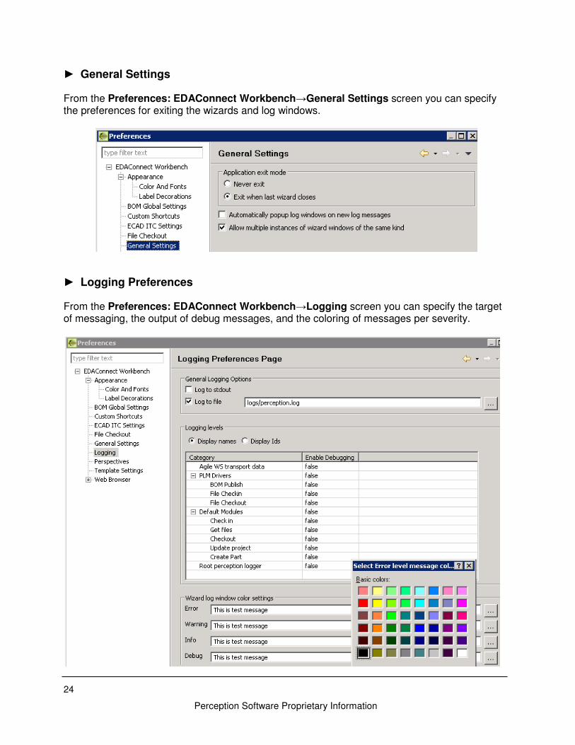
► General Settings
From the Preferences: EDAConnect Workbench→General Settings screen you can specify the preferences for exiting the wizards and log windows.
► Logging Preferences From the Preferences: EDAConnect Workbench→Logging screen you can specify the target of messaging, the output of debug messages, and the coloring of messages per severity.
25
Perception Software Proprietary Information
A relative path for Log to file, as specified here, will write to the installation EDAConnect-Dashboard folder. This field supports the use of an environment variable to identify the location of the log file. Use the format ${variableName} to specify the variable.
e.g. ${HOME}/logs/perception.log
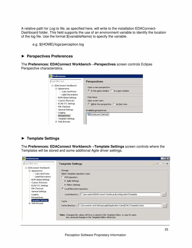
► Perspectives Preferences The Preferences: EDAConnect Workbench→Perspectives screen controls Eclipse Perspective characteristics.
► Template Settings
The Preferences: EDAConnect Workbench→Template Settings screen controls where the Templates will be stored and some additional Agile driver settings.
26
Perception Software Proprietary Information
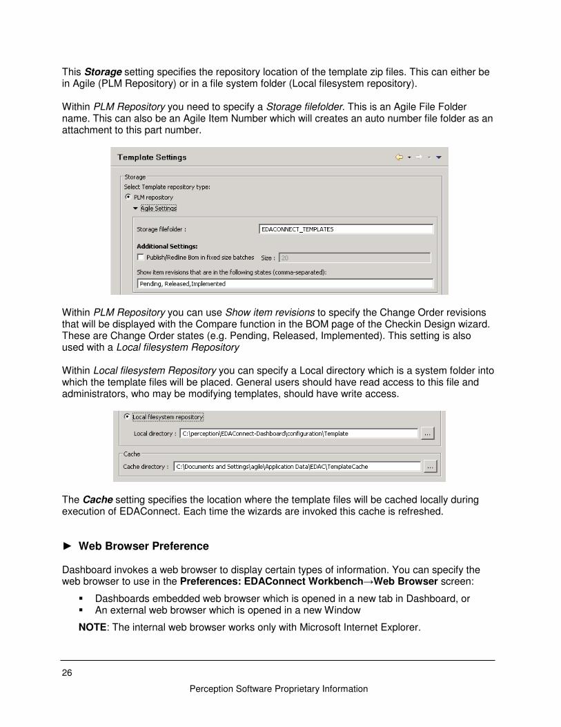
This Storage setting specifies the repository location of the template zip files. This can either be in Agile (PLM Repository) or in a file system folder (Local filesystem repository). Within PLM Repository you need to specify a Storage filefolder. This is an Agile File Folder name. This can also be an Agile Item Number which will creates an auto number file folder as an attachment to this part number.
Within PLM Repository you can use Show item revisions to specify the Change Order revisions that will be displayed with the Compare function in the BOM page of the Checkin Design wizard. These are Change Order states (e.g. Pending, Released, Implemented). This setting is also used with a Local filesystem Repository Within Local filesystem Repository you can specify a Local directory which is a system folder into which the template files will be placed. General users should have read access to this file and administrators, who may be modifying templates, should have write access.
The Cache setting specifies the location where the template files will be cached locally during execution of EDAConnect. Each time the wizards are invoked this cache is refreshed.
► Web Browser Preference Dashboard invokes a web browser to display certain types of information. You can specify the web browser to use in the Preferences: EDAConnect Workbench→Web Browser screen:
� Dashboards embedded web browser which is opened in a new tab in Dashboard, or � An external web browser which is opened in a new Window
NOTE: The internal web browser works only with Microsoft Internet Explorer.
27
Perception Software Proprietary Information
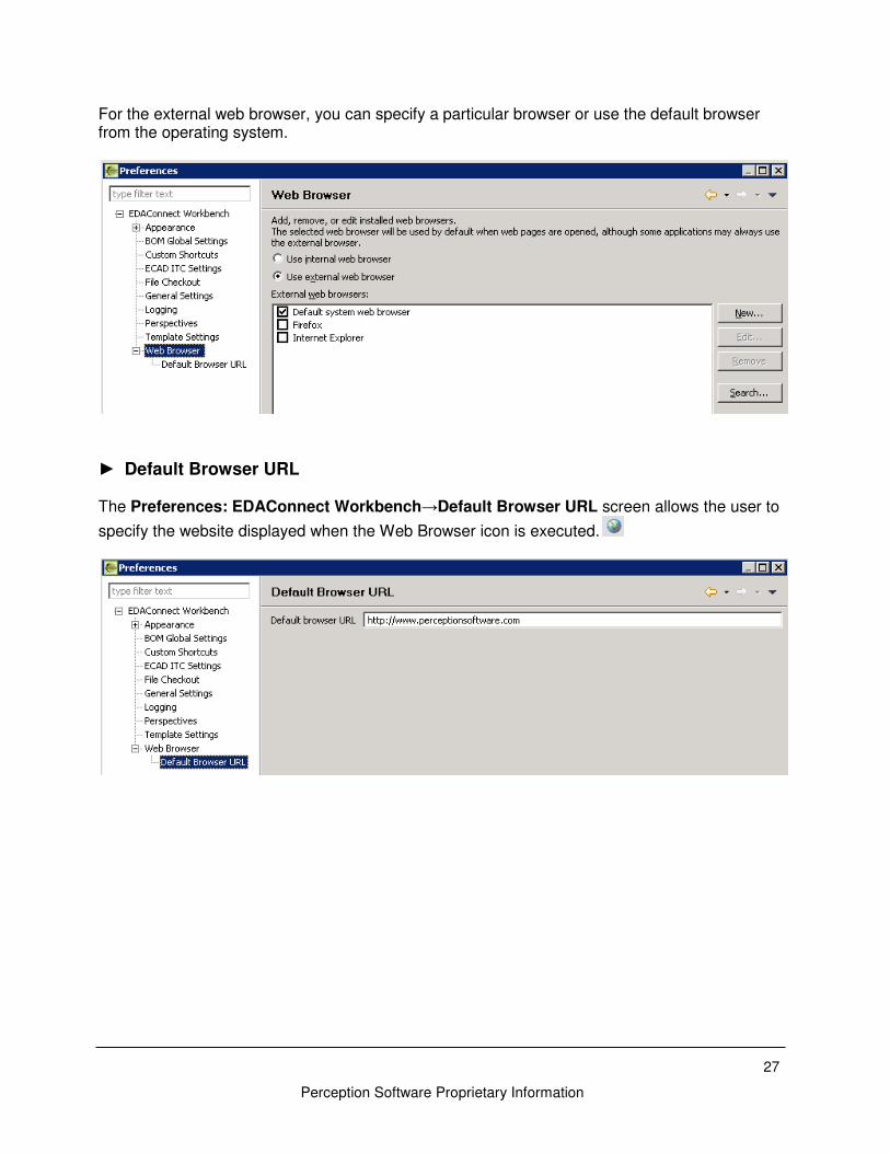
For the external web browser, you can specify a particular browser or use the default browser from the operating system.
► Default Browser URL The Preferences: EDAConnect Workbench→Default Browser URL screen allows the user to
specify the website displayed when the Web Browser icon is executed.
28
Perception Software Proprietary Information
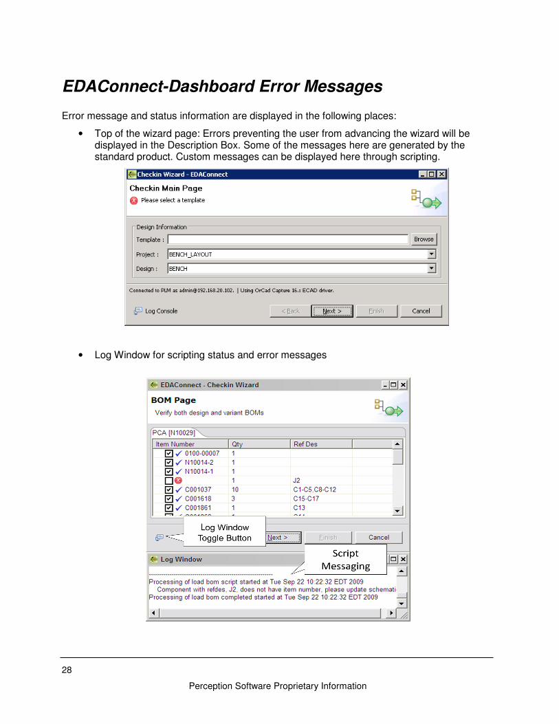
EDAConnect-Dashboard Error Messages Error message and status information are displayed in the following places:
• Top of the wizard page: Errors preventing the user from advancing the wizard will be displayed in the Description Box. Some of the messages here are generated by the standard product. Custom messages can be displayed here through scripting.
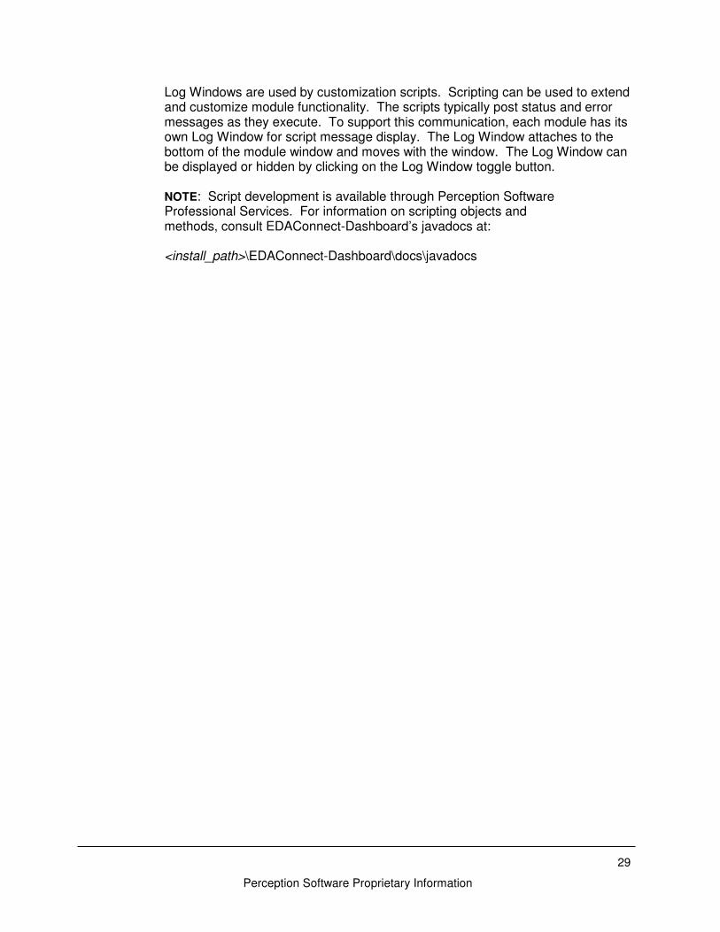
• Log Window for scripting status and error messages
29
Perception Software Proprietary Information
Log Windows are used by customization scripts. Scripting can be used to extend and customize module functionality. The scripts typically post status and error messages as they execute. To support this communication, each module has its own Log Window for script message display. The Log Window attaches to the bottom of the module window and moves with the window. The Log Window can be displayed or hidden by clicking on the Log Window toggle button.
NOTE: Script development is available through Perception Software Professional Services. For information on scripting objects and methods, consult EDAConnect-Dashboard’s javadocs at: <install_path>\EDAConnect-Dashboard\docs\javadocs
Perception Software Proprietary Information
EDAConnect Task Based Modules EDAConnect-Dashboard enables you to easily manage information transfer between your ECAD and PLM systems. EDAConnect-Dashboard gives you complete control over tasks such as:
• Design file check-in and check-out from PLM
• BOM extraction for release to PLM
• PLM Change Management processes interactions
• Creation of Agile Part definitions for schematic components This chapter describes how to perform common tasks associated with typical ECAD PLM Release task flows. The chapter is organized into the following sections:
• Checkin of Project Data to PLM
• Retrieving individual files from PLM
• Checkout of existing Project data from PLM
• Creation of Agile Part Number
Checkin of Project Data to PLM The Checkin Design module is used to publish project data to Agile. The project data includes design source and output files as well as the component BOM extracted automatically from the design. Optionally a change order can be created to advance the revision of this design data.
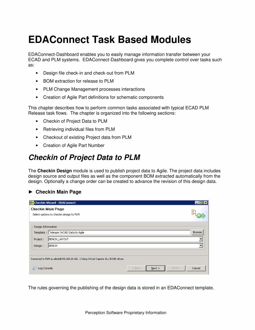
► Checkin Main Page
The rules governing the publishing of the design data is stored in an EDAConnect template.
31
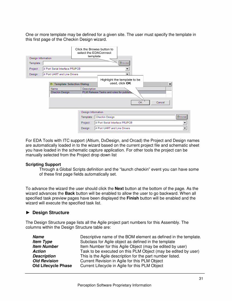
Perception Software Proprietary Information
One or more template may be defined for a given site. The user must specify the template in this first page of the Checkin Design wizard.
For EDA Tools with ITC support (Altium, DxDesign, and Orcad) the Project and Design names are automatically loaded in to the wizard based on the current project file and schematic sheet you have loaded in the schematic capture application. For other tools the project can be manually selected from the Project drop down list Scripting Support
Through a Global Scripts definition and the “launch checkin” event you can have some of these first page fields automatically set.
To advance the wizard the user should click the Next button at the bottom of the page. As the wizard advances the Back button will be enabled to allow the user to go backward. When all specified task preview pages have been displayed the Finish button will be enabled and the wizard will execute the specified task list.
► Design Structure The Design Structure page lists all the Agile project part numbers for this Assembly. The columns within the Design Structure table are:
Name Descriptive name of the BOM element as defined in the template. Item Type Subclass for Agile object as defined in the template Item Number Item Number for this Agile Object (may be edited by user) Action Task to be executed on this PLM Object (may be edited by user) Description This is the Agile description for the part number listed. Old Revision Current Revision in Agile for this PLM Object Old Lifecycle Phase Current Lifecycle in Agile for this PLM Object
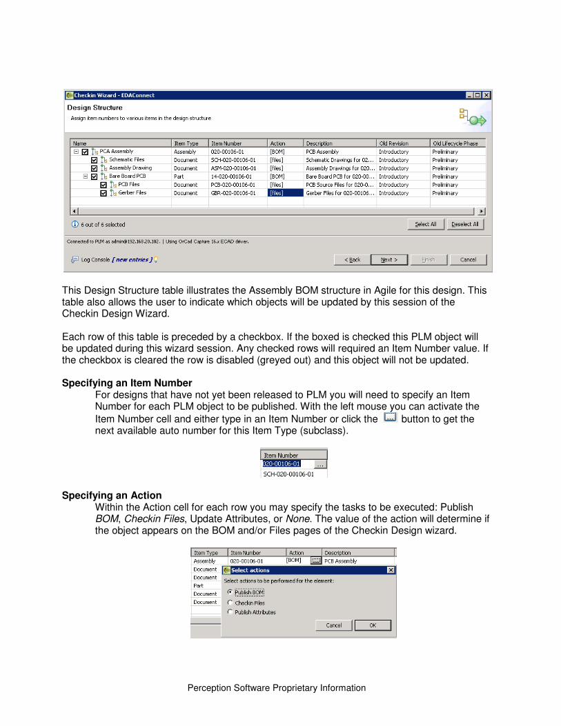
Perception Software Proprietary Information
This Design Structure table illustrates the Assembly BOM structure in Agile for this design. This table also allows the user to indicate which objects will be updated by this session of the Checkin Design Wizard. Each row of this table is preceded by a checkbox. If the boxed is checked this PLM object will be updated during this wizard session. Any checked rows will required an Item Number value. If the checkbox is cleared the row is disabled (greyed out) and this object will not be updated. Specifying an Item Number
For designs that have not yet been released to PLM you will need to specify an Item Number for each PLM object to be published. With the left mouse you can activate the
Item Number cell and either type in an Item Number or click the button to get the next available auto number for this Item Type (subclass).
Specifying an Action
Within the Action cell for each row you may specify the tasks to be executed: Publish BOM, Checkin Files, Update Attributes, or None. The value of the action will determine if the object appears on the BOM and/or Files pages of the Checkin Design wizard.
33
Perception Software Proprietary Information
Specifying an Description The first time through the wizard if the part number is not created yet in Agile the user can specify the Description. When the wizard page is advanced the part number is created in Agile and the Title Block.Description attribute will be updated. If the part number exists in Agile the current Description will be displayed.
Old Revision/Lifecycle Phase
These two fields are read-only and indicate the current revision and lifecycle stages of the part numbers within Agile. These values will be blank if the part numbers don’t yet exist in Agile.
Scripting Support By assigning a script to the Load Structure event you can have some of these cells automatically populated: Item Number, Action, Description, and selection checkbox. Through scripting you may also prevent a user from updating these fields once they have been set. Specifics on the scripting classes and methods are in the EDAConnect-Dashboard\docs\javadocs folder.
When you are processing against a change order each PLM object to be published, as indicated by the checkbox, will be added to the Affected Items list of the change order. Any new Item Numbers specified here will be created when you click Next to advance the wizard. All the values in this page are written to the EDAconnect metadata file in the ECAD project folder. This filename has the syntax: edac_md_<projectName>.xml. The next time you invoke the Checkin Design wizard on this design this metadata file is read this Design Structure page will have the values that were specified in the last session.
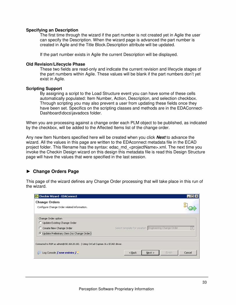
► Change Orders Page This page of the wizard defines any Change Order processing that will take place in this run of the wizard.
Perception Software Proprietary Information
Change Order Option
Update Preliminary Item
• This option can only be used if all the selected Design Structure part numbers are in a Preliminary Lifecycle state and none are currently on a Pending Change Order.
• With this option the Part Number will be updated directly and no Change Order will be created or updated.
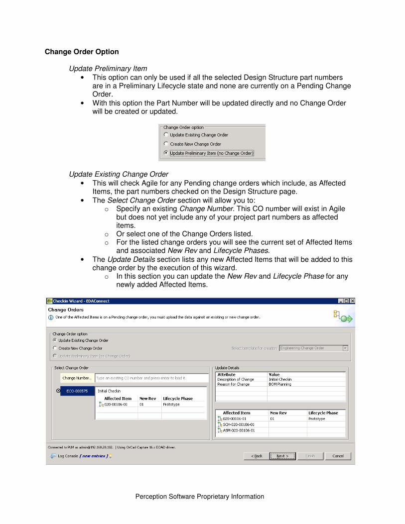
Update Existing Change Order
• This will check Agile for any Pending change orders which include, as Affected Items, the part numbers checked on the Design Structure page.
• The Select Change Order section will allow you to: o Specify an existing Change Number. This CO number will exist in Agile
but does not yet include any of your project part numbers as affected items.
o Or select one of the Change Orders listed. o For the listed change orders you will see the current set of Affected Items
and associated New Rev and Lifecycle Phases. • The Update Details section lists any new Affected Items that will be added to this
change order by the execution of this wizard. o In this section you can update the New Rev and Lifecycle Phase for any
newly added Affected Items.
35
Perception Software Proprietary Information
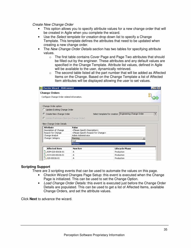
Create New Change Order • This option allows you to specify attribute values for a new change order that will
be created in Agile when you complete the wizard. • Use the Select template for creation drop down list to specify a Change
Template. This template defines the attributes that need to be updated when creating a new change order.
• The New Change Order Details section has two tables for specifying attribute values.
o The first table contains Cover Page and Page Two attributes that should be filled out by the engineer. These attributes and any default values are specified in the Change Template. Attribute list values, defined in Agile will be available to the user, dynamically retrieved.
o The second table listed all the part number that will be added as Affected Items on the Change. Based on the Change Template a list of Affected Item attributes will be displayed allowing the user to set values.
Scripting Support There are 3 scripting events that can be used to automate the values on this page.
• Checkin Wizard Changes Page Setup: this event is executed when the Change Page is initialized. This can be used to set the Change Option.
• Load Change Order Details: this event is executed just before the Change Order Details are populated. This can be used to get a list of Affected Items, available Change Orders, and set the attribute values.
Click Next to advance the wizard.

Perception Software Proprietary Information
► BOM Page In the BOM Page there will be a tab at the top for each PLM object that includes a Publish BOM Action per the Design Structure page. The label on the tab includes the Agile Item Number. All BOM sources defined in the EDAConnect template all will be executed and the BOM Page table will be filled with items to be published to PLM for each PLM object. The checkbox on the far left indicates the items to be published. For any part numbers found in Agile this checkbox is checked by default. The user can uncheck this box for specific items. Optionally, the template allows you to restrict updates to this checkbox. The second column will include a blue checkmark, if the part number was found in Agile or a red X if the part was not found in Agile. You can only publish items for part numbers that already exist in Agile. The first 3 fields are extracted from the BOM sources, this is generally the schematic. Optionally you can display additional columns with showing attribute values from Agile (.e.g. Lifecycle Phase, Description).
37
Perception Software Proprietary Information
Column Move & Sort You are now able to drag-and-drop columns within the table to reorder the display. You can sort on individual columns by clicking the column header with the left mouse button.
Value Copy
You are now able to grab and copy a piece of text from the BOM table. This is useful if you want to take a piece of text from the BOM table and search for that text in another file or in the PLM Search form. When you double-click a cell with the left string with that cell and put it within your paste buffer.
This functionality also works on the Item Number cell.
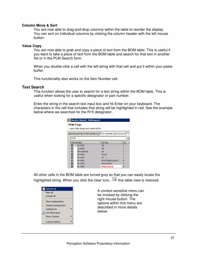
Text Search This function allows the user to search for a text string within the BOM table. This is useful when looking for a specific designator or part number. Enter the string in the search text input box and hit Enter on your keyboard. The characters in the cell that includes that string will be highlighted in red. See the example below where we searched for the R15 designator.
All other cells in the BOM table are turned grey so that you can easily locate the
highlighted string. When you click the clear icon, this table view is restored.
A context sensitive menu can be invoked by clicking the right mouse button. The options within this menu are described in more details below:
Perception Software Proprietary Information
• Refresh All – This will reload all the BOM sources and re-execute any scripting associated with the Load BOM event.
• Mark All – This will place a check off all BOM items • Unmark All – This will uncheck off all BOM items • Show Missing Items – This will apply an error icon to the left of the item number that
does not exist in PLM. • Unmark Missing Items – This will clear the checkbox from any BOM line who’s Item
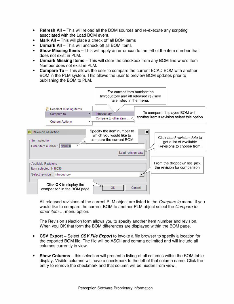
Number does not exist in PLM. • Compare To – This allows the user to compare the current ECAD BOM with another
BOM in the PLM system. This allows the user to preview BOM updates prior to publishing the BOM to PLM.
All released revisions of the current PLM object are listed in the Compare to menu. If you would like to compare the current BOM to another PLM object select the Compare to other item … menu option. The Revision selection form allows you to specify another Item Number and revision. When you OK that form the BOM differences are displayed within the BOM page.
• CSV Export – Select CSV File Export to invoke a file browser to specify a location for
the exported BOM file. The file will be ASCII and comma delimited and will include all columns currently in view.
• Show Columns – this selection will present a listing of all columns within the BOM table display. Visible columns will have a checkmark to the left of that column name. Click the entry to remove the checkmark and that column will be hidden from view.
39
Perception Software Proprietary Information
• Custom Actions – Through the EDAConnect template a menu option can be added
here which enable a script to be executed by the user. This is the BOM Table Menu event.
Scripting Support The Load BOM event can be used to retrieve data the BOM source data loading into this page when it is initialized. This even can also be update to set values, remove items, and set selection status.
Click Next to advance the wizard.
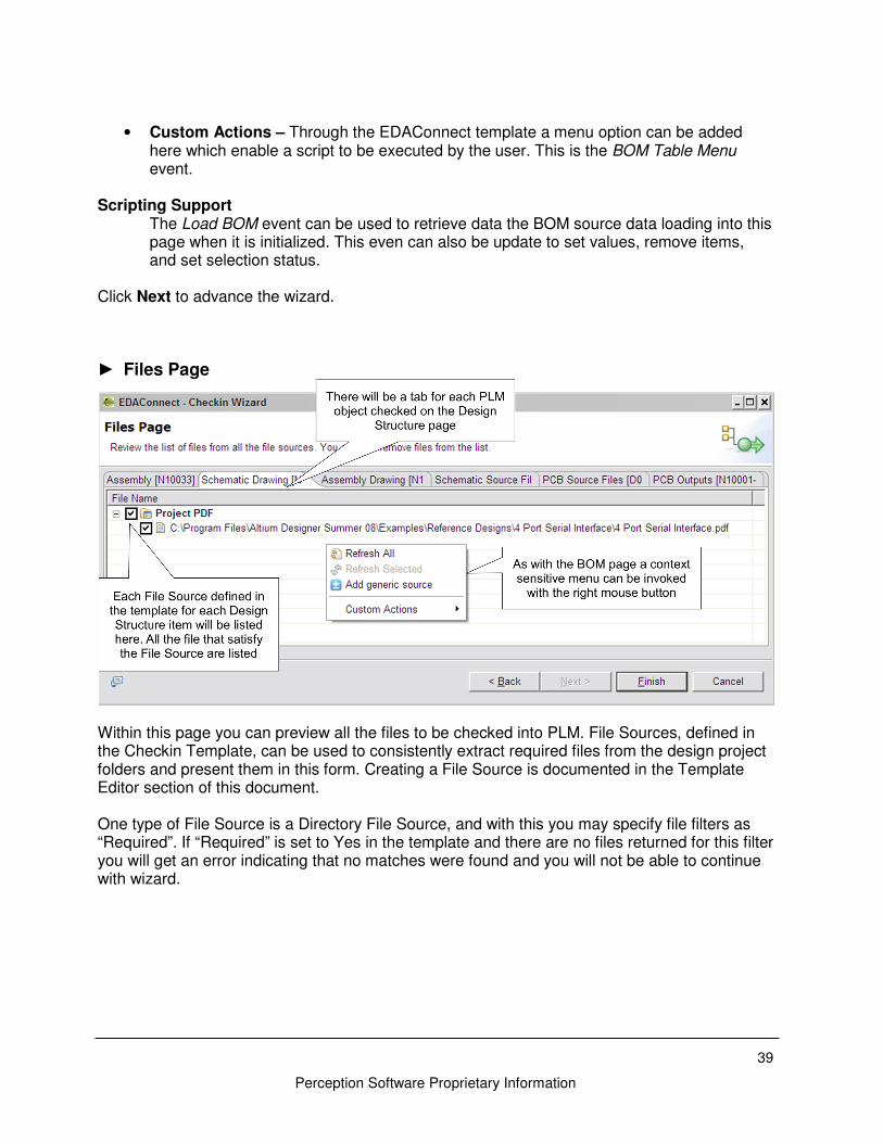
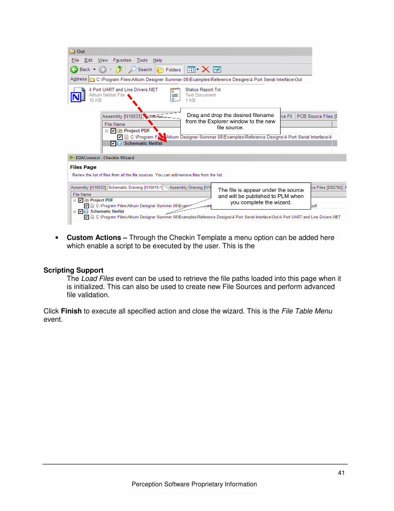
► Files Page
Within this page you can preview all the files to be checked into PLM. File Sources, defined in the Checkin Template, can be used to consistently extract required files from the design project folders and present them in this form. Creating a File Source is documented in the Template Editor section of this document. One type of File Source is a Directory File Source, and with this you may specify file filters as “Required”. If “Required” is set to Yes in the template and there are no files returned for this filter you will get an error indicating that no matches were found and you will not be able to continue with wizard.
Perception Software Proprietary Information
A context sensitive menu can be invoked by clicking the right mouse button. The options within this menu are described in more details below:
• Refresh All – This will reload all the File sources and re-execute any scripting associated with the Load Files event.
• Refresh Selected – This is enabled when a File Source has been selected. Executing this refreshed only the selected source. Refreshing the sources is helpful if the required files were not available at the time this page was drawn.
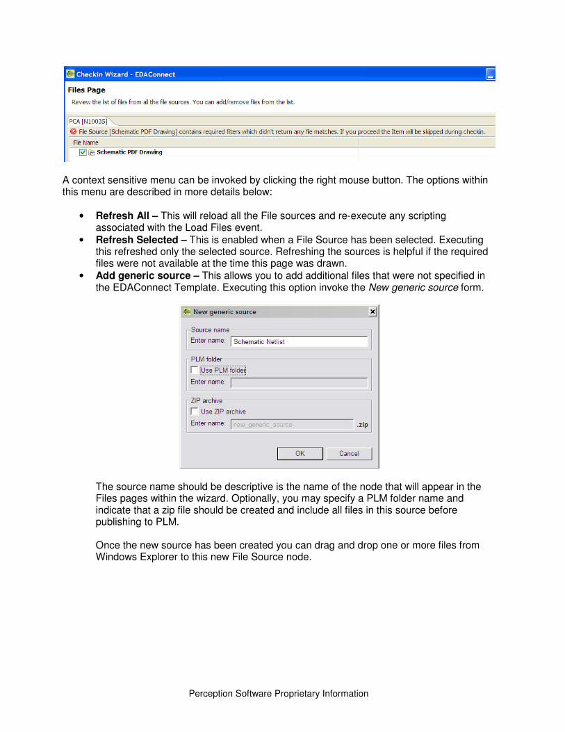
• Add generic source – This allows you to add additional files that were not specified in the EDAConnect Template. Executing this option invoke the New generic source form.
The source name should be descriptive is the name of the node that will appear in the Files pages within the wizard. Optionally, you may specify a PLM folder name and indicate that a zip file should be created and include all files in this source before publishing to PLM. Once the new source has been created you can drag and drop one or more files from Windows Explorer to this new File Source node.
41
Perception Software Proprietary Information
• Custom Actions – Through the Checkin Template a menu option can be added here which enable a script to be executed by the user. This is the
Scripting Support The Load Files event can be used to retrieve the file paths loaded into this page when it is initialized. This can also be used to create new File Sources and perform advanced file validation.
Click Finish to execute all specified action and close the wizard. This is the File Table Menu event.
Perception Software Proprietary Information
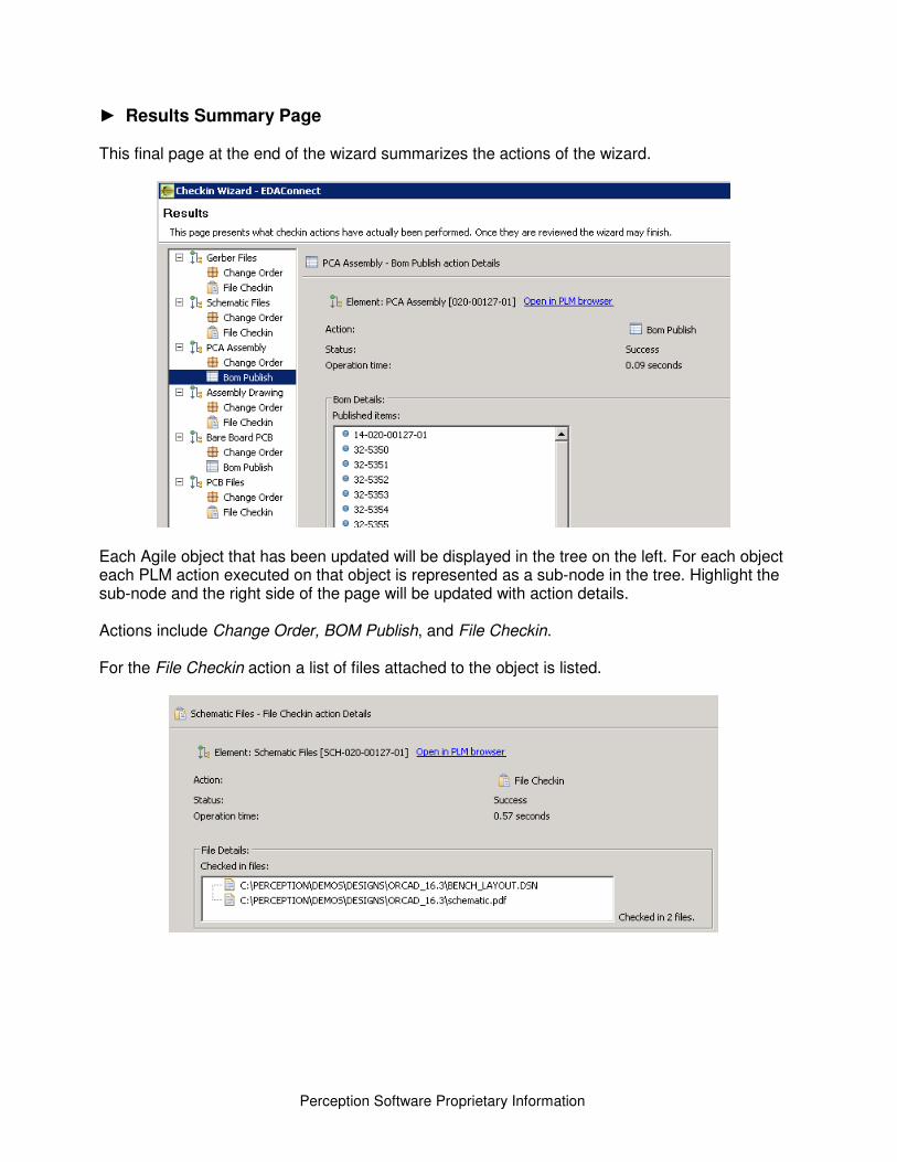
► Results Summary Page
This final page at the end of the wizard summarizes the actions of the wizard.
Each Agile object that has been updated will be displayed in the tree on the left. For each object each PLM action executed on that object is represented as a sub-node in the tree. Highlight the sub-node and the right side of the page will be updated with action details. Actions include Change Order, BOM Publish, and File Checkin. For the File Checkin action a list of files attached to the object is listed.
43
Perception Software Proprietary Information
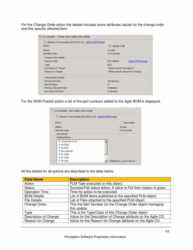
For the Change Order action the details includes some attributes values for the change order and this specific affected item.
For the BOM Publish action a list of the part numbers added to the Agile BOM is displayed.
All the details for all actions are described in the table below.
Field Name Description Action PLM Task executed on this object. Status Success/Fail status action. If value is Fail then reason is given. Operation Time Time for action to be executed. BOM Details List of BOM Items published to the specified PLM object. File Details List of Files attached to the specified PLM object. Change Order This the Item Number for the Change Order object managing
this update. Type This is the Type/Class of this Change Order object Description of Change Value for the Description of Change attribute on the Agile CO Reason for Change Value for the Reason for Change attribute on the Agile CO
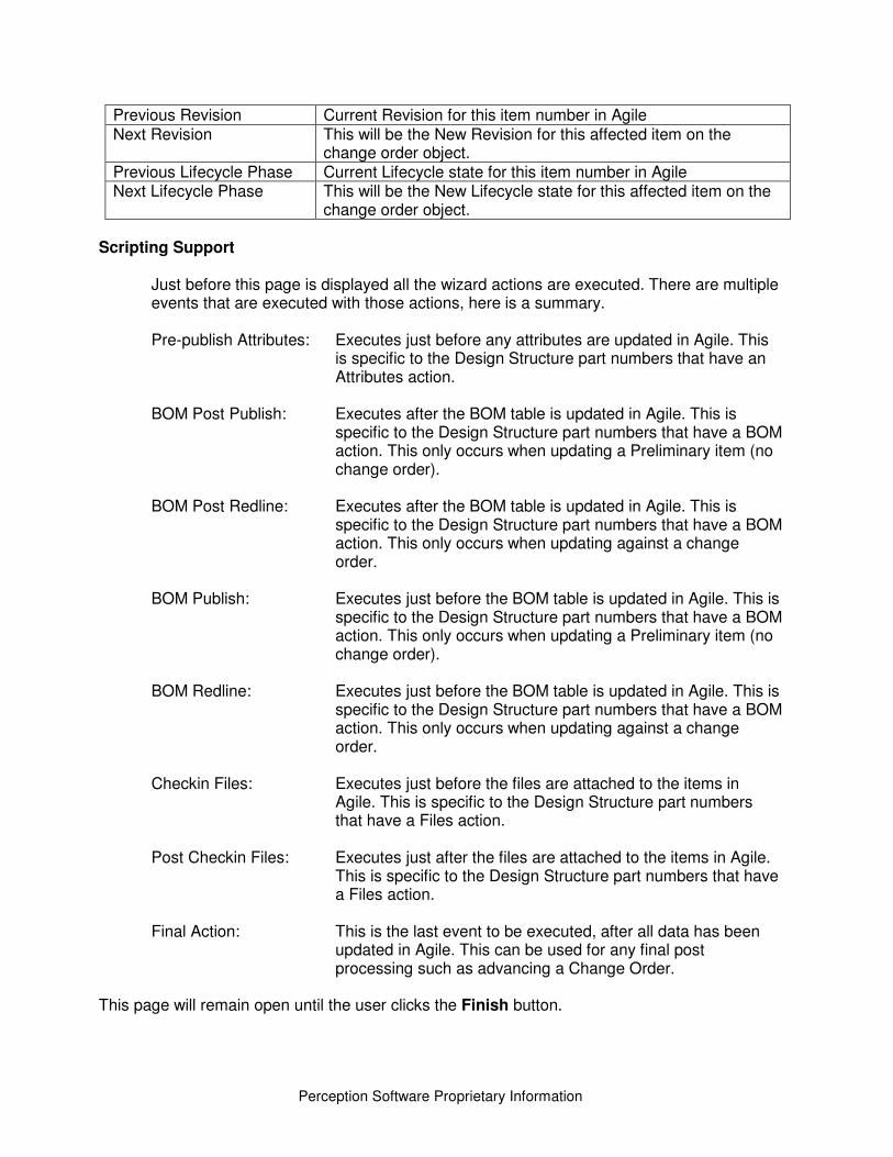
Perception Software Proprietary Information
Previous Revision Current Revision for this item number in Agile Next Revision This will be the New Revision for this affected item on the
change order object. Previous Lifecycle Phase Current Lifecycle state for this item number in Agile Next Lifecycle Phase This will be the New Lifecycle state for this affected item on the
change order object. Scripting Support
Just before this page is displayed all the wizard actions are executed. There are multiple events that are executed with those actions, here is a summary. Pre-publish Attributes: Executes just before any attributes are updated in Agile. This
is specific to the Design Structure part numbers that have an Attributes action.
BOM Post Publish: Executes after the BOM table is updated in Agile. This is
specific to the Design Structure part numbers that have a BOM action. This only occurs when updating a Preliminary item (no change order).
BOM Post Redline: Executes after the BOM table is updated in Agile. This is
specific to the Design Structure part numbers that have a BOM action. This only occurs when updating against a change order.
BOM Publish: Executes just before the BOM table is updated in Agile. This is
specific to the Design Structure part numbers that have a BOM action. This only occurs when updating a Preliminary item (no change order).
BOM Redline: Executes just before the BOM table is updated in Agile. This is
specific to the Design Structure part numbers that have a BOM action. This only occurs when updating against a change order.
Checkin Files: Executes just before the files are attached to the items in
Agile. This is specific to the Design Structure part numbers that have a Files action.
Post Checkin Files: Executes just after the files are attached to the items in Agile.
This is specific to the Design Structure part numbers that have a Files action.
Final Action: This is the last event to be executed, after all data has been
updated in Agile. This can be used for any final post processing such as advancing a Change Order.
This page will remain open until the user clicks the Finish button.
45
Perception Software Proprietary Information
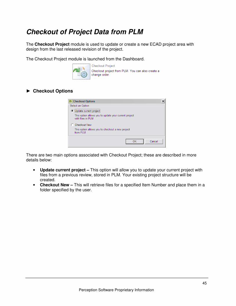
Checkout of Project Data from PLM The Checkout Project module is used to update or create a new ECAD project area with design from the last released revision of the project. The Checkout Project module is launched from the Dashboard.
► Checkout Options
There are two main options associated with Checkout Project; these are described in more details below:
• Update current project – This option will allow you to update your current project with files from a previous review, stored in PLM. Your existing project structure will be created.
• Checkout New – This will retrieve files for a specified Item Number and place them in a folder specified by the user.
Perception Software Proprietary Information
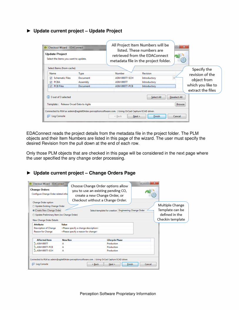
► Update current project – Update Project
EDAConnect reads the project details from the metadata file in the project folder. The PLM objects and their Item Numbers are listed in this page of the wizard. The user must specify the desired Revision from the pull down at the end of each row. Only those PLM objects that are checked in this page will be considered in the next page where the user specified the any change order processing.
► Update current project – Change Orders Page
47
Perception Software Proprietary Information
The Change Orders Page has the same functionality of the Change Orders page within the Checkin Design wizard. Here is a summary of the options but see page 34 for more details.
Update Preliminary Item
• This option can only be used if all the selected Design Structure part numbers are in a Preliminary Lifecycle state and none are currently on a Pending Change Order.
Update Existing Change Order
• This will check Agile for any Pending change orders which include, as Affected Items, the part numbers checked on the Design Structure page.
Create New Change Order
• This option allows you to specify attribute values for a new change order that will be created in Agile when you complete the wizard.
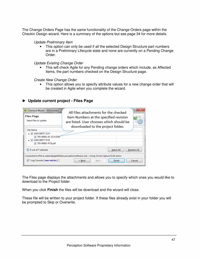
► Update current project - Files Page
The Files page displays the attachments and allows you to specify which ones you would like to download to the Project folder. When you click Finish the files will be download and the wizard will close.
These file will be written to your project folder. If these files already exist in your folder you will be prompted to Skip or Overwrite.
Perception Software Proprietary Information
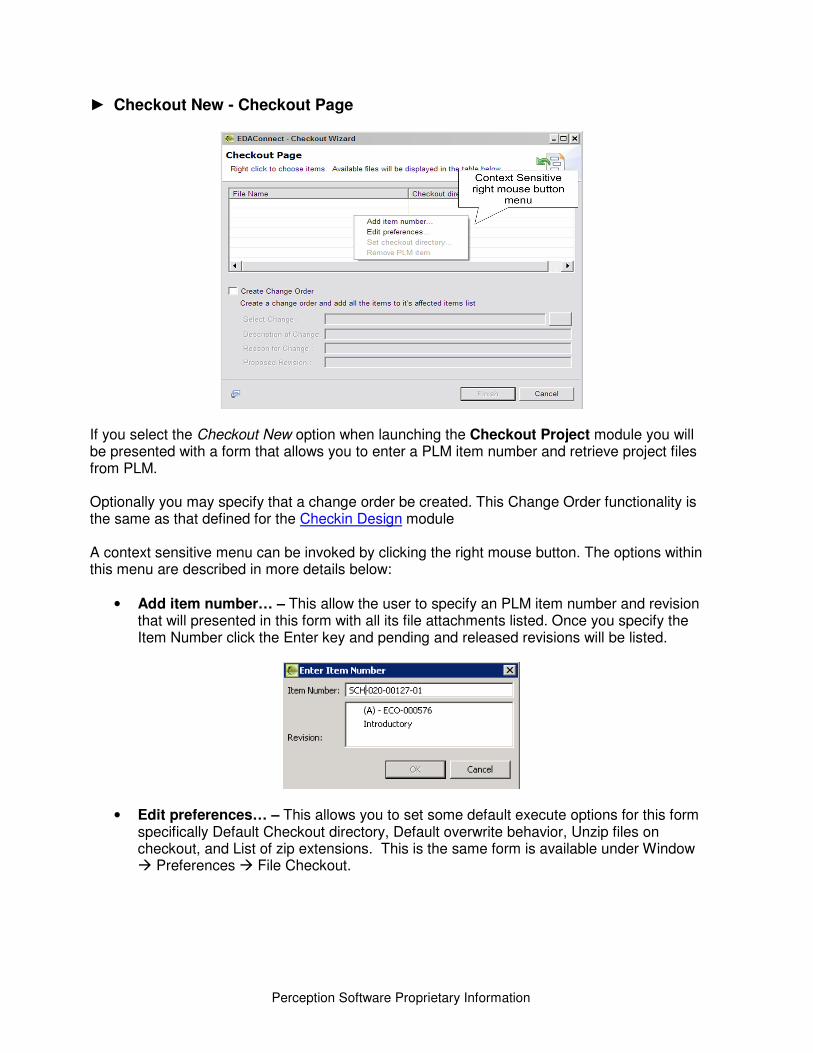
► Checkout New - Checkout Page
If you select the Checkout New option when launching the Checkout Project module you will be presented with a form that allows you to enter a PLM item number and retrieve project files from PLM. Optionally you may specify that a change order be created. This Change Order functionality is the same as that defined for the Checkin Design module A context sensitive menu can be invoked by clicking the right mouse button. The options within this menu are described in more details below:
• Add item number… – This allow the user to specify an PLM item number and revision that will presented in this form with all its file attachments listed. Once you specify the Item Number click the Enter key and pending and released revisions will be listed.
• Edit preferences… – This allows you to set some default execute options for this form specifically Default Checkout directory, Default overwrite behavior, Unzip files on checkout, and List of zip extensions. This is the same form is available under Window � Preferences � File Checkout.
49
Perception Software Proprietary Information
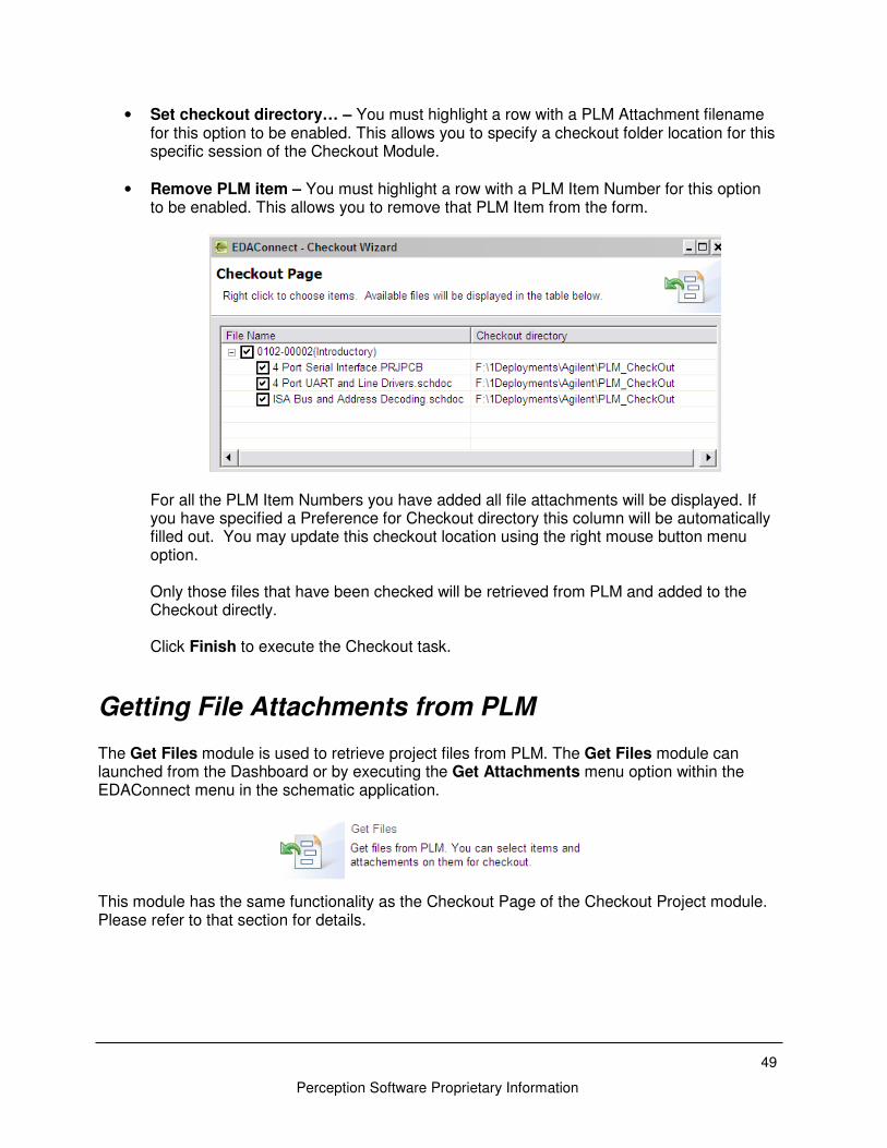
• Set checkout directory… – You must highlight a row with a PLM Attachment filename for this option to be enabled. This allows you to specify a checkout folder location for this specific session of the Checkout Module.
• Remove PLM item – You must highlight a row with a PLM Item Number for this option to be enabled. This allows you to remove that PLM Item from the form.
For all the PLM Item Numbers you have added all file attachments will be displayed. If you have specified a Preference for Checkout directory this column will be automatically filled out. You may update this checkout location using the right mouse button menu option. Only those files that have been checked will be retrieved from PLM and added to the Checkout directly. Click Finish to execute the Checkout task.
Getting File Attachments from PLM The Get Files module is used to retrieve project files from PLM. The Get Files module can launched from the Dashboard or by executing the Get Attachments menu option within the EDAConnect menu in the schematic application.
This module has the same functionality as the Checkout Page of the Checkout Project module. Please refer to that section for details.
Perception Software Proprietary Information
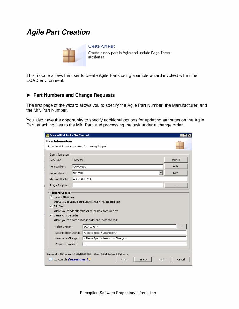
Agile Part Creation
This module allows the user to create Agile Parts using a simple wizard invoked within the ECAD environment.
► Part Numbers and Change Requests
The first page of the wizard allows you to specify the Agile Part Number, the Manufacturer, and the Mfr. Part Number. You also have the opportunity to specify additional options for updating attributes on the Agile Part, attaching files to the Mfr. Part, and processing the task under a change order.
51
Perception Software Proprietary Information
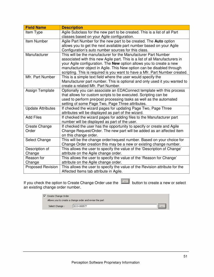
Field Name Description
Item Type Agile Subclass for the new part to be created. This is a list of all Part classes based on your Agile configuration.
Item Number Agile Part Number for the new part to be created. The Auto option allows you to get the next available part number based on your Agile Configuration’s auto number sources for this class.
Manufacturer This will be the manufacturer for the Manufacturer Part Number associated with this new Agile part. This is a list of all Manufacturers in your Agile configuration. The New option allows you to create a new manufacturer object in Agile. This New option can be disabled through scripting. This is required is you want to have a Mfr. Part Number created.
Mfr. Part Number This is a simple text field where the user would specify the Manufacturer part number. This is optional and only used it you wanted to create a related Mfr. Part Number.
Assign Template Optionally you can associate an EDAConnect template with this process that allows for custom scripts to be executed. Scripting can be used to perform pre/post processing tasks as well as the automated setting of some Page Two, Page Three attributes.
Update Attributes If checked the wizard pages for updating Page Two, Page Three attributes will be displayed as part of the wizard.
Add Files If checked the wizard pages for adding files to the Manufacturer part number will be displayed as part of the user.
Create Change Order
If checked the user has the opportunity to specify or create and Agile Change Request/Order. The new part will be added as an affected item on this change order.
Select Change This will be the change order/request number. Based on your choice for Change Order creation this may be a new or existing change number.
Description of Change
This allows the user to specify the value of the ‘Description of Change’ attribute on the Agile change order.
Reason for Change
This allows the user to specify the value of the ‘Reason for Change’ attribute on the Agile change order.
Proposed Revision This allows the user to specify the value of the Revision attribute for the Affected Items tab attribute in Agile.
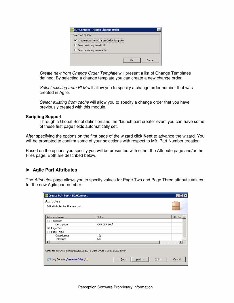
If you check the option to Create Change Order use the button to create a new or select an existing change order number.
Perception Software Proprietary Information
Create new from Change Order Template will present a list of Change Templates defined. By selecting a change template you can create a new change order. Select existing from PLM will allow you to specify a change order number that was created in Agile. Select existing from cache will allow you to specify a change order that you have previously created with this module.
Scripting Support
Through a Global Script definition and the “launch part create” event you can have some of these first page fields automatically set.
After specifying the options on the first page of the wizard click Next to advance the wizard. You will be prompted to confirm some of your selections with respect to Mfr. Part Number creation. Based on the options you specify you will be presented with either the Attribute page and/or the Files page. Both are described below.
► Agile Part Attributes
The Attributes page allows you to specify values for Page Two and Page Three attribute values for the new Agile part number.
53
Perception Software Proprietary Information
All Page 2 and Page 3 attributes are listed based on your Agile configuration. If there are lists for any of these attributes the list are also made available to the user. Setting of these attributes is based on the user’s roles and privileges defined in Agile.
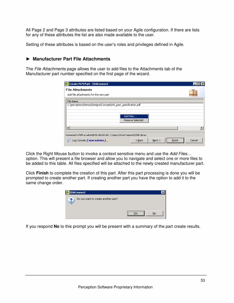
► Manufacturer Part File Attachments
The File Attachments page allows the user to add files to the Attachments tab of the Manufacturer part number specified on the first page of the wizard.
Click the Right Mouse button to invoke a context sensitive menu and use the Add Files… option. This will present a file browser and allow you to navigate and select one or more files to be added to this table. All files specified will be attached to the newly created manufacturer part. Click Finish to complete the creation of this part. After this part processing is done you will be prompted to create another part. If creating another part you have the option to add it to the same change order.
If you respond No to this prompt you will be present with a summary of the part create results.
Perception Software Proprietary Information
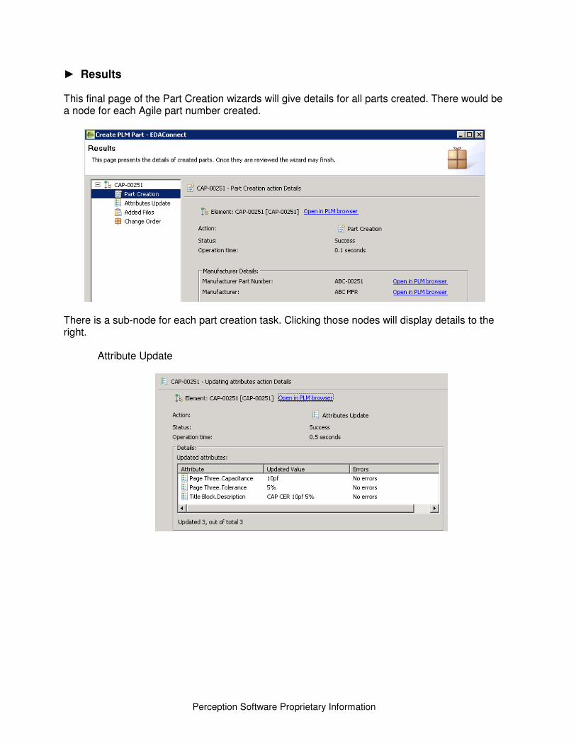
► Results This final page of the Part Creation wizards will give details for all parts created. There would be a node for each Agile part number created.
There is a sub-node for each part creation task. Clicking those nodes will display details to the right.
Attribute Update
55
Perception Software Proprietary Information
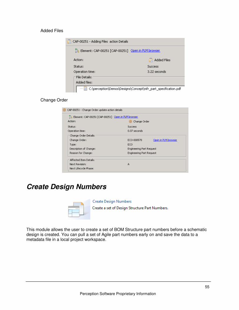
Added Files
Change Order
Create Design Numbers
This module allows the user to create a set of BOM Structure part numbers before a schematic design is created. You can pull a set of Agile part numbers early on and save the data to a metadata file in a local project workspace.
Perception Software Proprietary Information
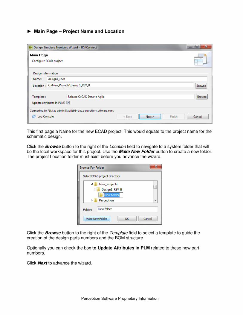
► Main Page – Project Name and Location
This first page a Name for the new ECAD project. This would equate to the project name for the schematic design. Click the Browse button to the right of the Location field to navigate to a system folder that will be the local workspace for this project. Use the Make New Folder button to create a new folder. The project Location folder must exist before you advance the wizard.
Click the Browse button to the right of the Template field to select a template to guide the creation of the design parts numbers and the BOM structure. Optionally you can check the box to Update Attributes in PLM related to these new part numbers. Click Next to advance the wizard.
57
Perception Software Proprietary Information
► Design Structure Page
This page has the same functionality as the Design Structure page in the Checkin Design wizard. This is defined on page 31. Click Next to advance the wizard. The Item Numbers specified in the Design Structure page will be created at this point.
► Attributes Page
Perception Software Proprietary Information
If you opted to update attributes you will be presented with the Attributes page. All of the Design Structure items will be listed on the left. You can select one of those items and the right panel will update with Title Block, Page Two, and Page Three attributes for this item. With scripting you can reduce the number of attributes presented and default some values. Click Next to advance the wizard.
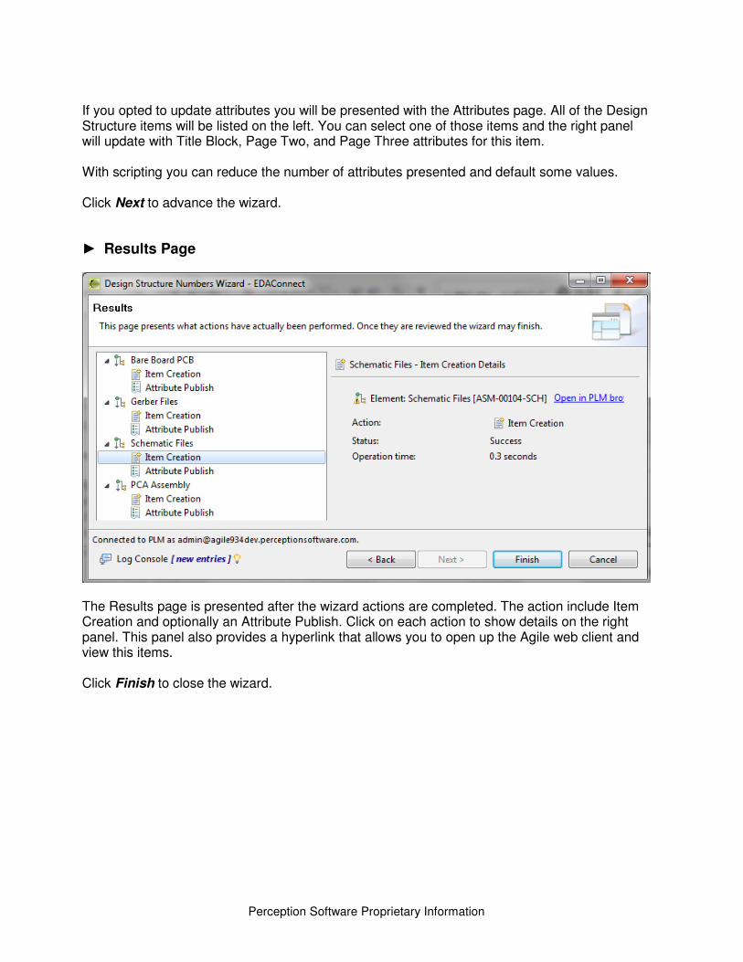
► Results Page
The Results page is presented after the wizard actions are completed. The action include Item Creation and optionally an Attribute Publish. Click on each action to show details on the right panel. This panel also provides a hyperlink that allows you to open up the Agile web client and view this items. Click Finish to close the wizard.
59
Perception Software Proprietary Information
EDAConnect Templates
Introduction EDAConnect-Dashboard Templates provide a systematic way to specify a set of rules that govern the release processing. The templates allow for ECAD and Agile to agree on a programmatic, enforceable and consistent means of moving data between the two systems. Templates are XML-based files stored within a compressed zip file. Templates are used by Checkin Design module and the New Part Creation module. Templates are created via the EDAConnect-Dashboard Template Editor and may be stored in Agile or a shared folder on your file system for central control and access. You may create as many Templates as necessary. The number of templates required per site is a function of the EDA tools being used. A template typically contains the following sections:
• Attribute Mappings – Defines attribute mappings between ECAD and PLM
• Change Templates – Defines Change Order templates for various workflows
• Design Structure – Defined the project structure to exist in PLM and contain the project files and BOM items.
• BOM Sources – Specifies files and scripts for BOM extraction
• File Sources – Specifies rules for identifying the design files to be loaded to PLM
• Attribute Sources – Specifies files and scripts for attribute extraction
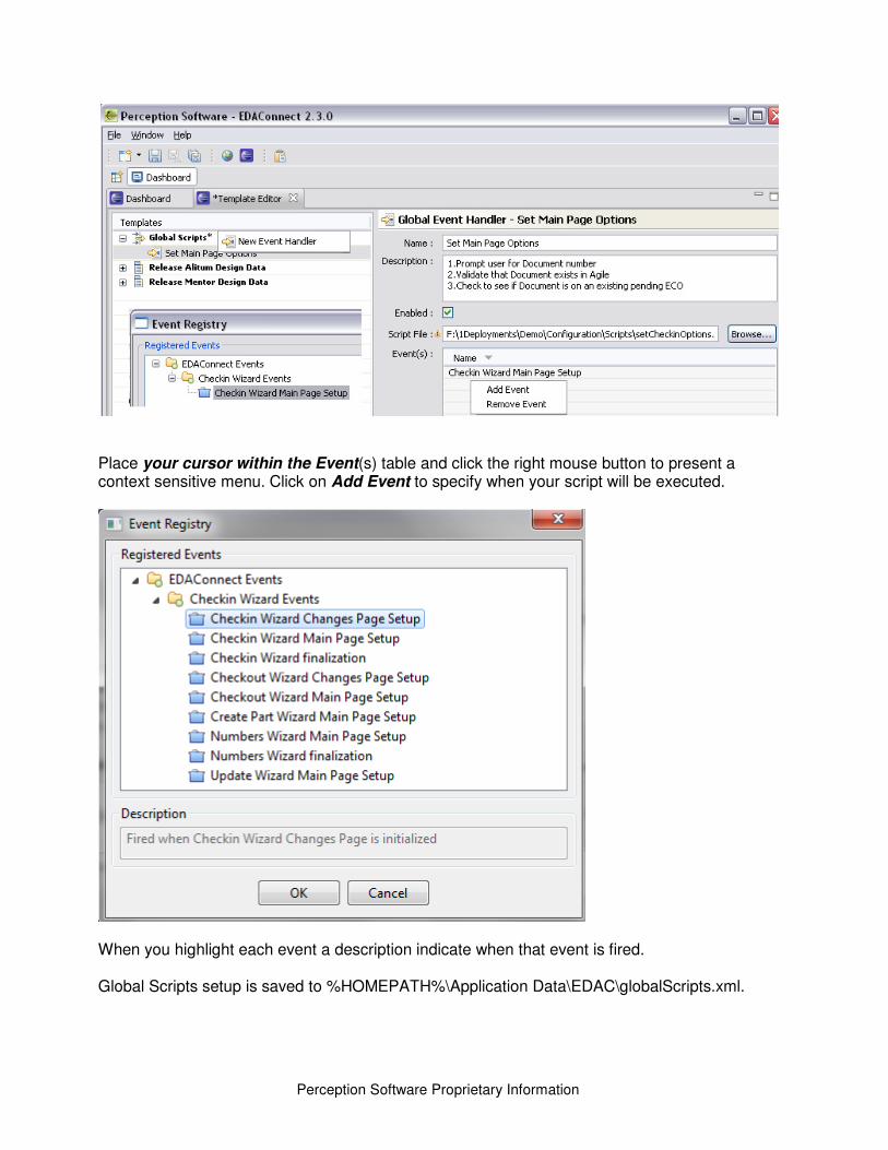
• Event Handlers – Associates customization scripts with trigger events These sections are described in detail in Global Scripts Within the template editor you can now specify a script that will be executed when you launch the Checkin Design module. Scripting classes are available to programmatically specify the template, select publish options, and specify Change Order details. See the EDAConnect-Dashboard/docs/javadocs for details. From the Global Scripts node within the Template Editor click the right mouse button and select the option for New Event Handler. On the right specify the event details including Name, Description, Script File, and Event.
Perception Software Proprietary Information
Place your cursor within the Event(s) table and click the right mouse button to present a context sensitive menu. Click on Add Event to specify when your script will be executed.
When you highlight each event a description indicate when that event is fired. Global Scripts setup is saved to %HOMEPATH%\Application Data\EDAC\globalScripts.xml.

61
Perception Software Proprietary Information
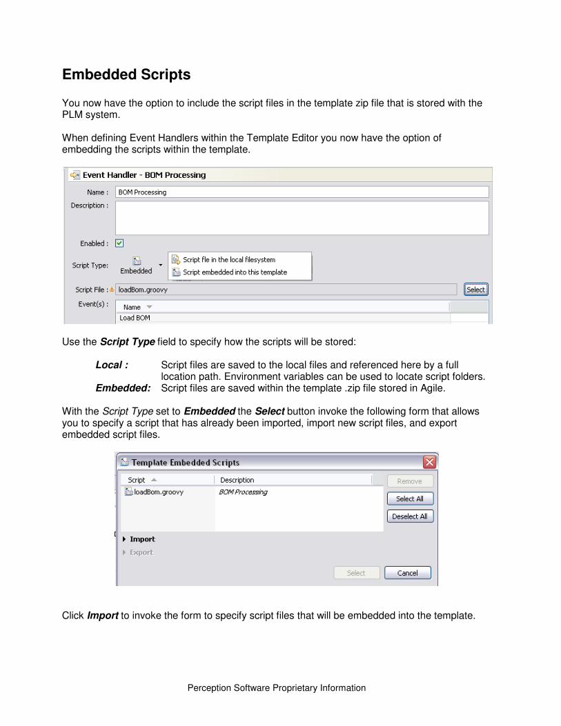
Embedded Scripts
You now have the option to include the script files in the template zip file that is stored with the PLM system. When defining Event Handlers within the Template Editor you now have the option of embedding the scripts within the template.
Use the Script Type field to specify how the scripts will be stored:
Local : Script files are saved to the local files and referenced here by a full location path. Environment variables can be used to locate script folders.
Embedded: Script files are saved within the template .zip file stored in Agile.
With the Script Type set to Embedded the Select button invoke the following form that allows you to specify a script that has already been imported, import new script files, and export embedded script files.
Click Import to invoke the form to specify script files that will be embedded into the template.
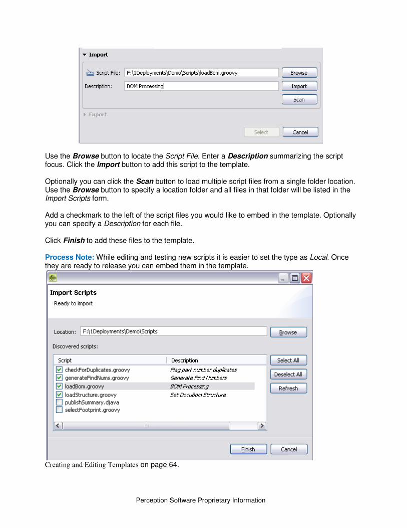
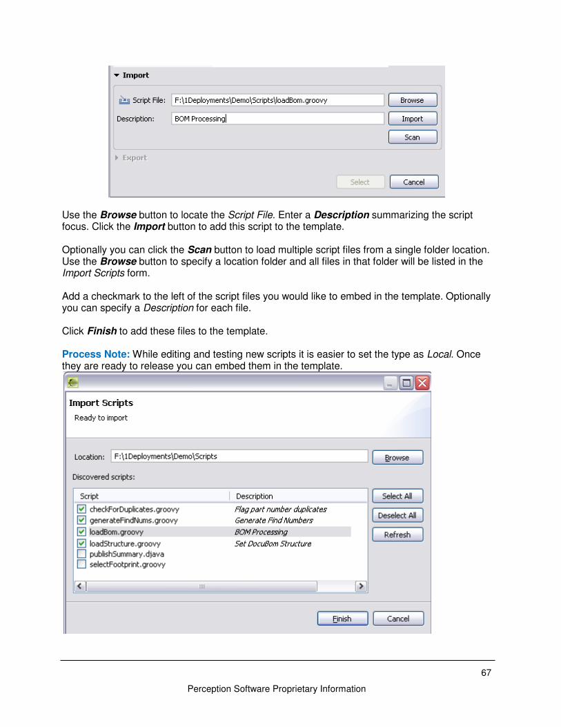
Perception Software Proprietary Information
Use the Browse button to locate the Script File. Enter a Description summarizing the script focus. Click the Import button to add this script to the template. Optionally you can click the Scan button to load multiple script files from a single folder location. Use the Browse button to specify a location folder and all files in that folder will be listed in the Import Scripts form. Add a checkmark to the left of the script files you would like to embed in the template. Optionally you can specify a Description for each file. Click Finish to add these files to the template. Process Note: While editing and testing new scripts it is easier to set the type as Local. Once they are ready to release you can embed them in the template.
Creating and Editing Templates on page 64.
63
Perception Software Proprietary Information
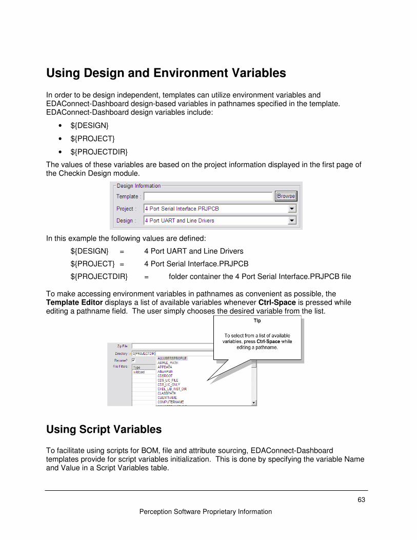
Using Design and Environment Variables In order to be design independent, templates can utilize environment variables and EDAConnect-Dashboard design-based variables in pathnames specified in the template. EDAConnect-Dashboard design variables include:
• ${DESIGN}
• ${PROJECT}
• ${PROJECTDIR}
The values of these variables are based on the project information displayed in the first page of the Checkin Design module.
In this example the following values are defined:
${DESIGN} = 4 Port UART and Line Drivers
${PROJECT} = 4 Port Serial Interface.PRJPCB
${PROJECTDIR} = folder container the 4 Port Serial Interface.PRJPCB file To make accessing environment variables in pathnames as convenient as possible, the Template Editor displays a list of available variables whenever Ctrl-Space is pressed while editing a pathname field. The user simply chooses the desired variable from the list.
Using Script Variables To facilitate using scripts for BOM, file and attribute sourcing, EDAConnect-Dashboard templates provide for script variables initialization. This is done by specifying the variable Name and Value in a Script Variables table.
Perception Software Proprietary Information
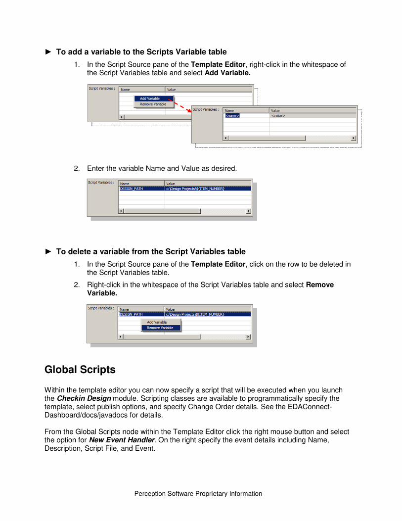
► To add a variable to the Scripts Variable table
1. In the Script Source pane of the Template Editor, right-click in the whitespace of the Script Variables table and select Add Variable.
2. Enter the variable Name and Value as desired.
► To delete a variable from the Script Variables table
1. In the Script Source pane of the Template Editor, click on the row to be deleted in the Script Variables table.
2. Right-click in the whitespace of the Script Variables table and select Remove Variable.
Global Scripts
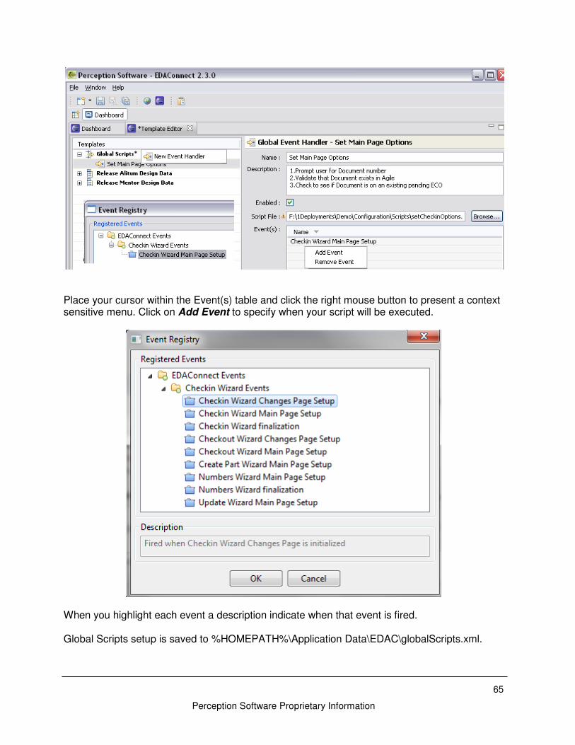
Within the template editor you can now specify a script that will be executed when you launch the Checkin Design module. Scripting classes are available to programmatically specify the template, select publish options, and specify Change Order details. See the EDAConnect-Dashboard/docs/javadocs for details. From the Global Scripts node within the Template Editor click the right mouse button and select the option for New Event Handler. On the right specify the event details including Name, Description, Script File, and Event.
65
Perception Software Proprietary Information
Place your cursor within the Event(s) table and click the right mouse button to present a context sensitive menu. Click on Add Event to specify when your script will be executed.
When you highlight each event a description indicate when that event is fired. Global Scripts setup is saved to %HOMEPATH%\Application Data\EDAC\globalScripts.xml.
Perception Software Proprietary Information
Embedded Scripts
You now have the option to include the script files in the template zip file that is stored with the PLM system. When defining Event Handlers within the Template Editor you now have the option of embedding the scripts within the template.
Use the Script Type field to specify how the scripts will be stored:
Local : Script files are saved to the local files and referenced here by a full location path. Environment variables can be used to locate script folders.
Embedded: Script files are saved within the template .zip file stored in Agile.
With the Script Type set to Embedded the Select button invoke the following form that allows you to specify a script that has already been imported, import new script files, and export embedded script files.
Click Import to invoke the form to specify script files that will be embedded into the template.
67
Perception Software Proprietary Information
Use the Browse button to locate the Script File. Enter a Description summarizing the script focus. Click the Import button to add this script to the template. Optionally you can click the Scan button to load multiple script files from a single folder location. Use the Browse button to specify a location folder and all files in that folder will be listed in the Import Scripts form. Add a checkmark to the left of the script files you would like to embed in the template. Optionally you can specify a Description for each file. Click Finish to add these files to the template. Process Note: While editing and testing new scripts it is easier to set the type as Local. Once they are ready to release you can embed them in the template.
Perception Software Proprietary Information
Creating and Editing Templates Templates are used to specify the files to be extracted for a design and to map the extracted data from the design domain into the PLM domain. EDAConnect-Dashboard templates should always be created and edited using the Template Editor module. This chapter describes how to use the Template Editor.
WARNING: While it is possible to edit the template XML files outside the Template Editor, this practice is not recommended due to the risk of introducing syntax errors into the template.
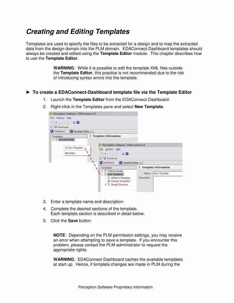
► To create a EDAConnect-Dashboard template file via the Template Editor
1. Launch the Template Editor from the EDAConnect-Dashboard.
2. Right-click in the Templates pane and select New Template.
3. Enter a template name and description.
4. Complete the desired sections of the template. Each template section is described in detail below.
5. Click the Save button.
NOTE: Depending on the PLM permission settings, you may receive an error when attempting to save a template. If you encounter this problem, please contact the PLM administrator to request the appropriate rights. WARNING: EDAConnect-Dashboard caches the available templates at start up. Hence, if template changes are made in PLM during the
69
Perception Software Proprietary Information
EDAConnect-Dashboard session, they will not be visible to any of the modules until the EDAConnect-Dashboard is stopped and restarted.
Attribute Mappings It is common for the ECAD attribute names to be different than those utilized within PLM. To establish the mapping between the two, mappings are specified in the Attribute Mappings form of the template. These mappings apply to all BOM Sources specified in the template. However, global mappings can be overridden by local attribute mappings specified within a BOM Source template form.
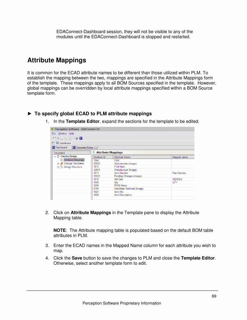
► To specify global ECAD to PLM attribute mappings
1. In the Template Editor, expand the sections for the template to be edited.
2. Click on Attribute Mappings in the Template pane to display the Attribute Mapping table.
NOTE: The Attribute mapping table is populated based on the default BOM table attributes in PLM.
3. Enter the ECAD names in the Mapped Name column for each attribute you wish to map.
4. Click the Save button to save the changes to PLM and close the Template Editor. Otherwise, select another template form to edit.
Perception Software Proprietary Information
Change Templates Many of the field values used in a PLM Change Order form are the same from Change Order to Change Order and must be repeatedly entered by the user. The ability to pre-populate PLM Change Order information saves the user from having to re-enter the same values each time. EDAConnect-Dashboard facilitates this through Change Templates. The Change Template allows the user to specify the following items:
• Change Type
• Auto Number Source for Change Order Number
• Change Description
• Reason for Change
• Workflow
• PLM Attribute default values NOTE: The options for Change Type, Auto Number Source, and Workflow have been predefined in your PLM Data Model.
To specify a Change Template
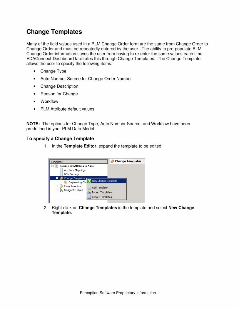
1. In the Template Editor, expand the template to be edited.
2. Right-click on Change Templates in the template and select New Change Template.
71
Perception Software Proprietary Information
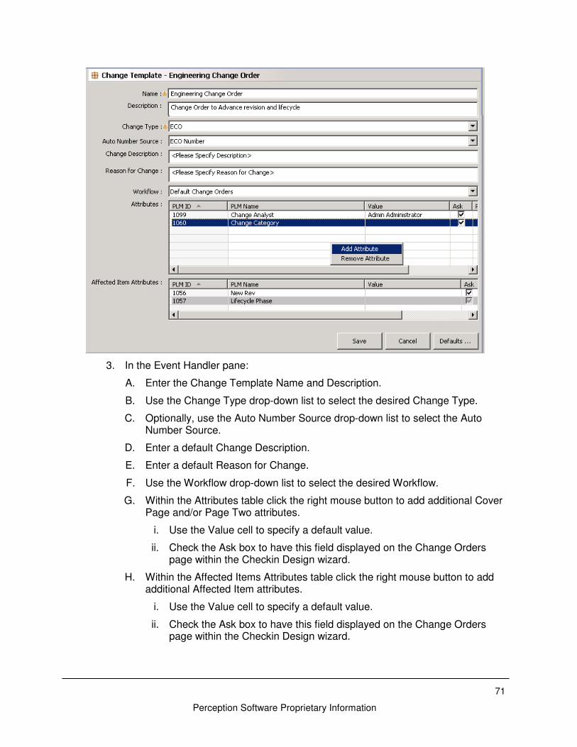
3. In the Event Handler pane:
A. Enter the Change Template Name and Description.
B. Use the Change Type drop-down list to select the desired Change Type.
C. Optionally, use the Auto Number Source drop-down list to select the Auto Number Source.
D. Enter a default Change Description.
E. Enter a default Reason for Change.
F. Use the Workflow drop-down list to select the desired Workflow.
G. Within the Attributes table click the right mouse button to add additional Cover Page and/or Page Two attributes.
i. Use the Value cell to specify a default value.
ii. Check the Ask box to have this field displayed on the Change Orders page within the Checkin Design wizard.
H. Within the Affected Items Attributes table click the right mouse button to add additional Affected Item attributes.
i. Use the Value cell to specify a default value.
ii. Check the Ask box to have this field displayed on the Change Orders page within the Checkin Design wizard.
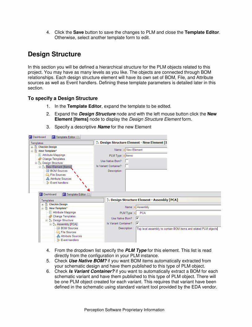
Perception Software Proprietary Information
4. Click the Save button to save the changes to PLM and close the Template Editor. Otherwise, select another template form to edit.
Design Structure In this section you will be defined a hierarchical structure for the PLM objects related to this project. You may have as many levels as you like. The objects are connected through BOM relationships. Each design structure element will have its own set of BOM, File, and Attribute sources as well as Event handlers. Defining these template parameters is detailed later in this section.
To specify a Design Structure
1. In the Template Editor, expand the template to be edited.
2. Expand the Design Structure node and with the left mouse button click the New Element [Items] node to display the Design Structure Element form.
3. Specify a descriptive Name for the new Element
4. From the dropdown list specify the PLM Type for this element. This list is read directly from the configuration in your PLM instance.
5. Check Use Native BOM? if you want BOM items automatically extracted from your schematic design and have them published to this type of PLM object.
6. Check Is Variant Container? if you want to automatically extract a BOM for each schematic variant and have them published to this type of PLM object. There will be one PLM object created for each variant. This requires that variant have been defined in the schematic using standard variant tool provided by the EDA vendor.
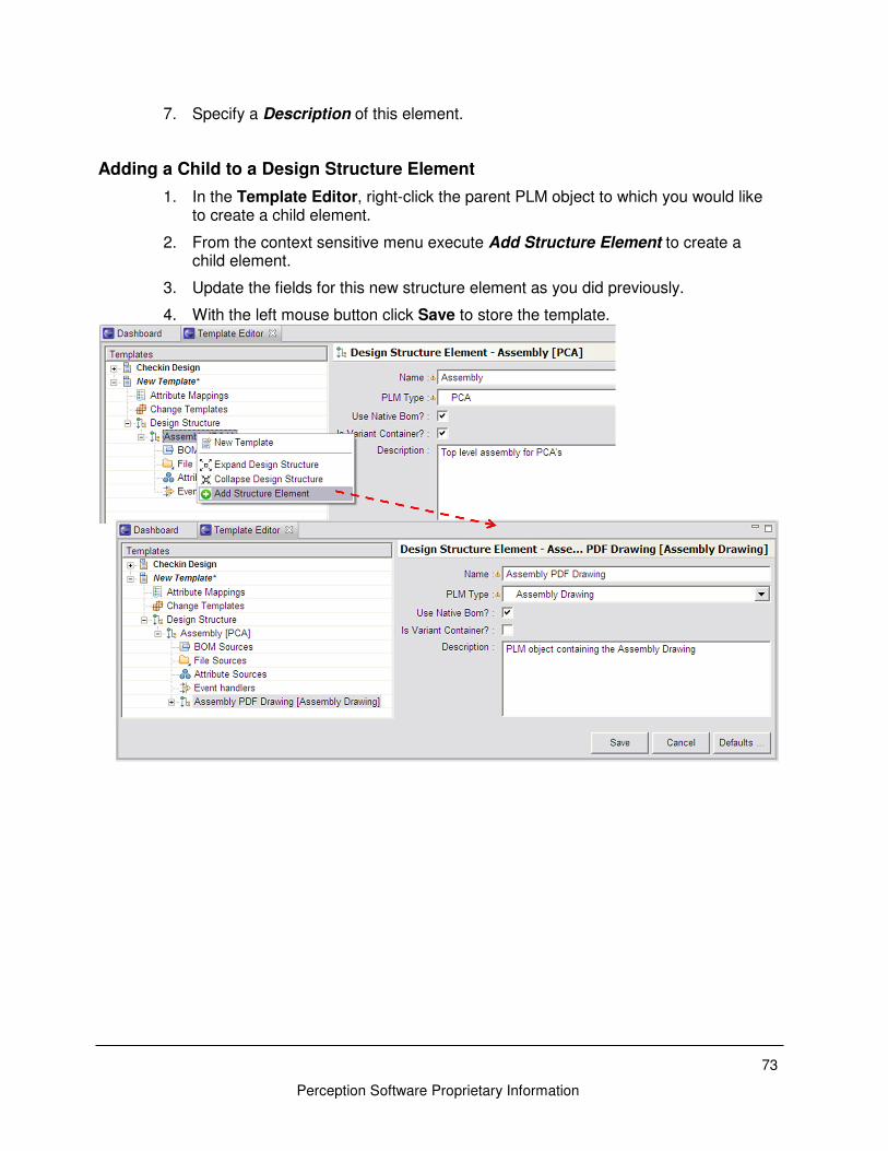
73
Perception Software Proprietary Information
7. Specify a Description of this element.
Adding a Child to a Design Structure Element
1. In the Template Editor, right-click the parent PLM object to which you would like to create a child element.
2. From the context sensitive menu execute Add Structure Element to create a child element.
3. Update the fields for this new structure element as you did previously.
4. With the left mouse button click Save to store the template.
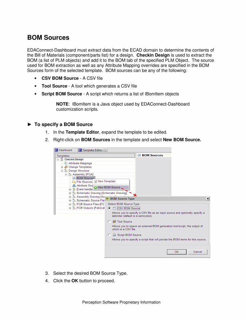
Perception Software Proprietary Information
BOM Sources EDAConnect-Dashboard must extract data from the ECAD domain to determine the contents of the Bill of Materials (component/parts list) for a design. Checkin Design is used to extract the BOM (a list of PLM objects) and add it to the BOM tab of the specified PLM Object. The source used for BOM extraction as well as any Attribute Mapping overrides are specified in the BOM Sources form of the selected template. BOM sources can be any of the following:
• CSV BOM Source - A CSV file
• Tool Source - A tool which generates a CSV file
• Script BOM Source - A script which returns a list of IBomItem objects
NOTE: IBomItem is a Java object used by EDAConnect-Dashboard customization scripts.
► To specify a BOM Source
1. In the Template Editor, expand the template to be edited.
2. Right-click on BOM Sources in the template and select New BOM Source.
3. Select the desired BOM Source Type.
4. Click the OK button to proceed.
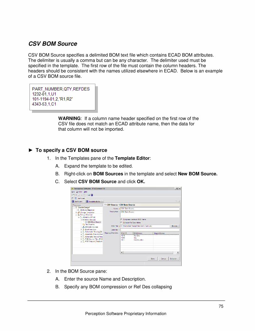
75
Perception Software Proprietary Information
CSV BOM Source CSV BOM Source specifies a delimited BOM text file which contains ECAD BOM attributes. The delimiter is usually a comma but can be any character. The delimiter used must be specified in the template. The first row of the file must contain the column headers. The headers should be consistent with the names utilized elsewhere in ECAD. Below is an example of a CSV BOM source file.
WARNING: If a column name header specified on the first row of the CSV file does not match an ECAD attribute name, then the data for that column will not be imported.
► To specify a CSV BOM source
1. In the Templates pane of the Template Editor:
A. Expand the template to be edited.
B. Right-click on BOM Sources in the template and select New BOM Source.
C. Select CSV BOM Source and click OK.
2. In the BOM Source pane:
A. Enter the source Name and Description.
B. Specify any BOM compression or Ref Des collapsing
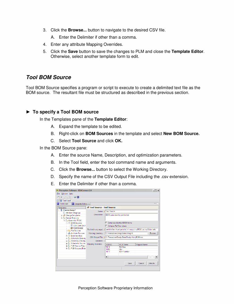
Perception Software Proprietary Information
3. Click the Browse... button to navigate to the desired CSV file.
A. Enter the Delimiter if other than a comma.
4. Enter any attribute Mapping Overrides.
5. Click the Save button to save the changes to PLM and close the Template Editor. Otherwise, select another template form to edit.
Tool BOM Source Tool BOM Source specifies a program or script to execute to create a delimited text file as the BOM source. The resultant file must be structured as described in the previous section.
► To specify a Tool BOM source
In the Templates pane of the Template Editor:
A. Expand the template to be edited.
B. Right-click on BOM Sources in the template and select New BOM Source.
C. Select Tool Source and click OK.
In the BOM Source pane:
A. Enter the source Name, Description, and optimization parameters.
B. In the Tool field, enter the tool command name and arguments.
C. Click the Browse... button to select the Working Directory.
D. Specify the name of the CSV Output File including the .csv extension.
E. Enter the Delimiter if other than a comma.
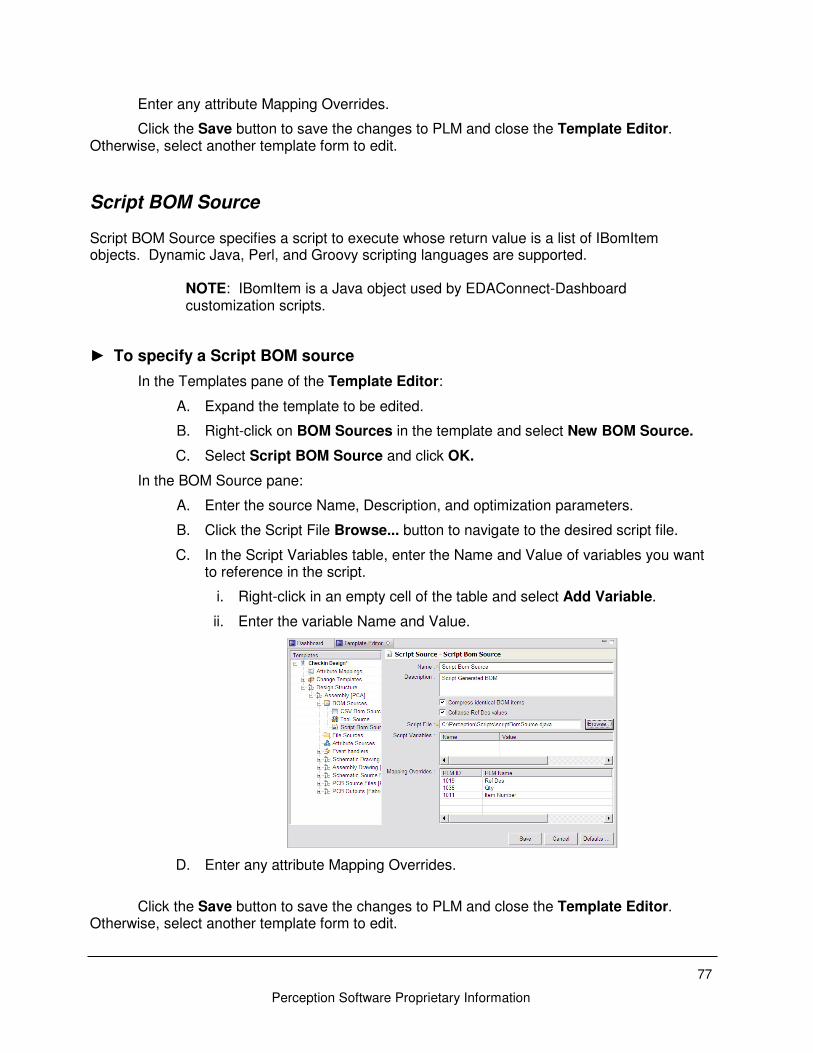
77
Perception Software Proprietary Information
Enter any attribute Mapping Overrides.
Click the Save button to save the changes to PLM and close the Template Editor. Otherwise, select another template form to edit.
Script BOM Source Script BOM Source specifies a script to execute whose return value is a list of IBomItem objects. Dynamic Java, Perl, and Groovy scripting languages are supported.
NOTE: IBomItem is a Java object used by EDAConnect-Dashboard customization scripts.
► To specify a Script BOM source
In the Templates pane of the Template Editor:
A. Expand the template to be edited.
B. Right-click on BOM Sources in the template and select New BOM Source.
C. Select Script BOM Source and click OK.
In the BOM Source pane:
A. Enter the source Name, Description, and optimization parameters.
B. Click the Script File Browse... button to navigate to the desired script file.
C. In the Script Variables table, enter the Name and Value of variables you want to reference in the script.
i. Right-click in an empty cell of the table and select Add Variable.
ii. Enter the variable Name and Value.
D. Enter any attribute Mapping Overrides.
Click the Save button to save the changes to PLM and close the Template Editor. Otherwise, select another template form to edit.
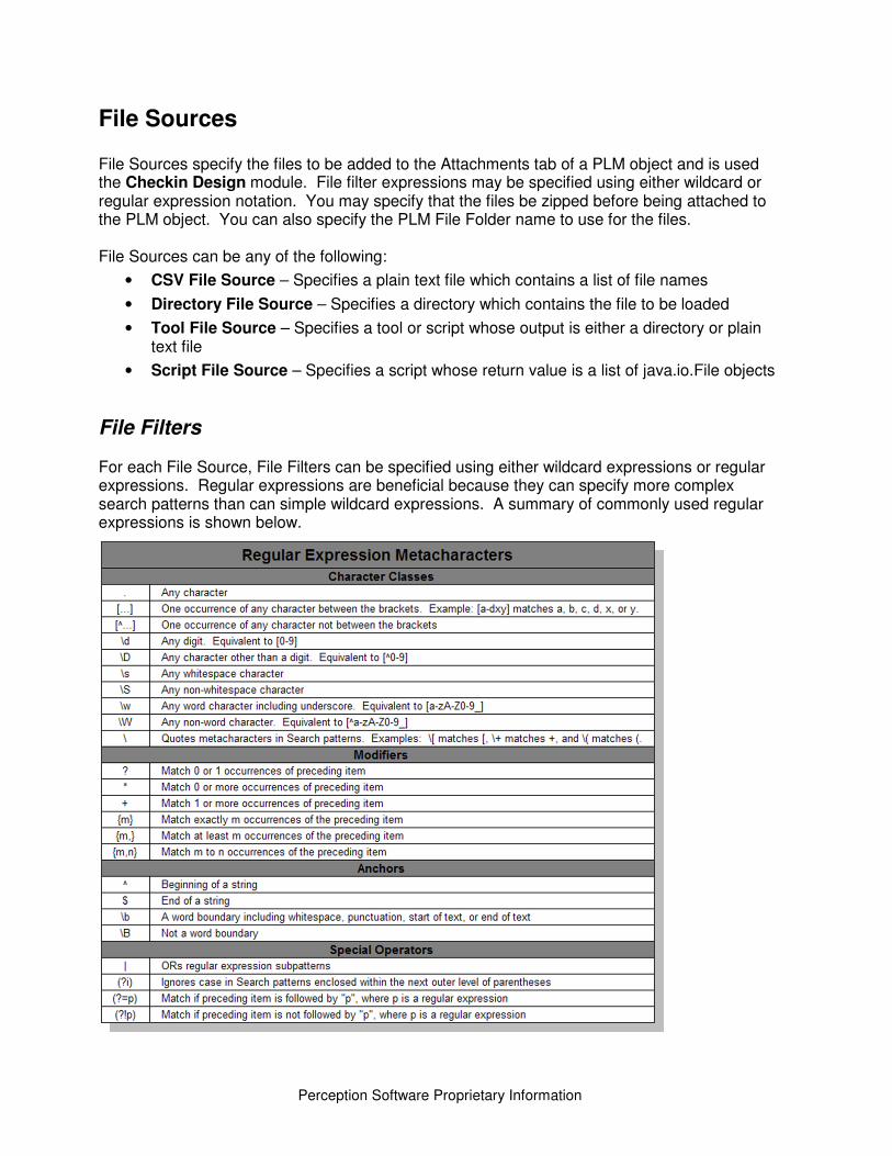
Perception Software Proprietary Information
File Sources File Sources specify the files to be added to the Attachments tab of a PLM object and is used the Checkin Design module. File filter expressions may be specified using either wildcard or regular expression notation. You may specify that the files be zipped before being attached to the PLM object. You can also specify the PLM File Folder name to use for the files. File Sources can be any of the following:
• CSV File Source – Specifies a plain text file which contains a list of file names
• Directory File Source – Specifies a directory which contains the file to be loaded
• Tool File Source – Specifies a tool or script whose output is either a directory or plain text file
• Script File Source – Specifies a script whose return value is a list of java.io.File objects
File Filters For each File Source, File Filters can be specified using either wildcard expressions or regular expressions. Regular expressions are beneficial because they can specify more complex search patterns than can simple wildcard expressions. A summary of commonly used regular expressions is shown below.
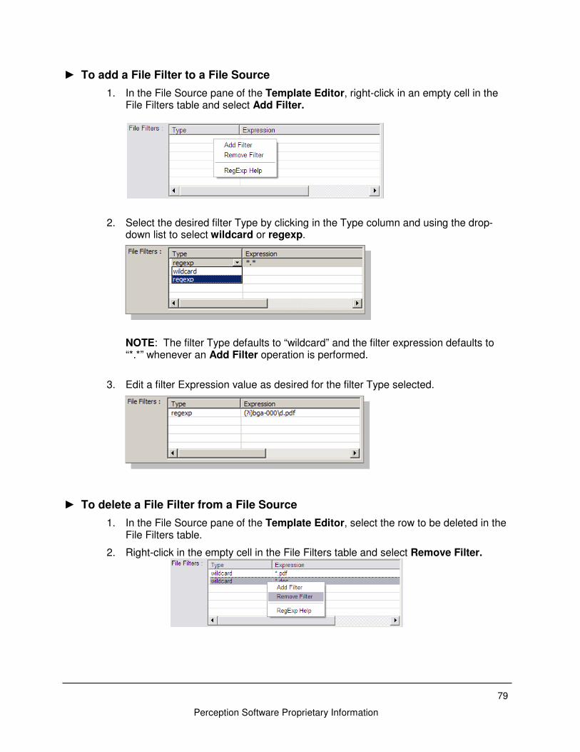
79
Perception Software Proprietary Information
► To add a File Filter to a File Source
1. In the File Source pane of the Template Editor, right-click in an empty cell in the File Filters table and select Add Filter.
2. Select the desired filter Type by clicking in the Type column and using the drop-down list to select wildcard or regexp. NOTE: The filter Type defaults to “wildcard” and the filter expression defaults to “*.*” whenever an Add Filter operation is performed.
3. Edit a filter Expression value as desired for the filter Type selected.
► To delete a File Filter from a File Source
1. In the File Source pane of the Template Editor, select the row to be deleted in the File Filters table.
2. Right-click in the empty cell in the File Filters table and select Remove Filter.
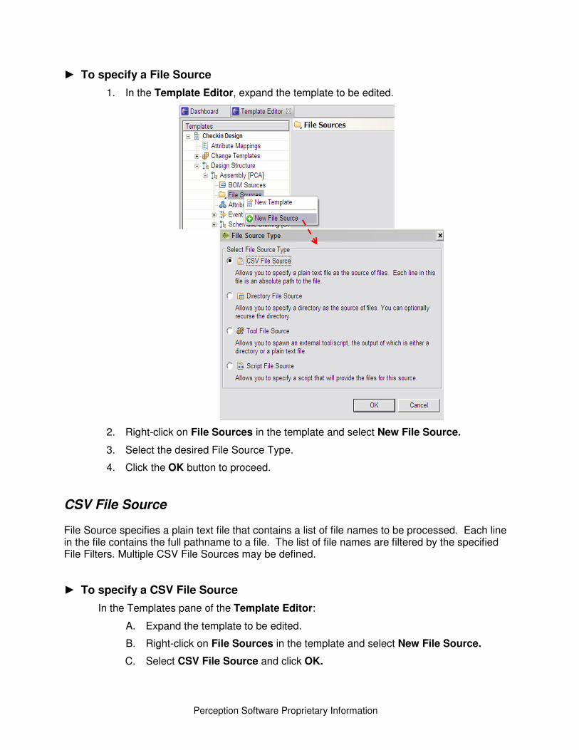
Perception Software Proprietary Information
► To specify a File Source
1. In the Template Editor, expand the template to be edited.
2. Right-click on File Sources in the template and select New File Source.
3. Select the desired File Source Type.
4. Click the OK button to proceed.
CSV File Source File Source specifies a plain text file that contains a list of file names to be processed. Each line in the file contains the full pathname to a file. The list of file names are filtered by the specified File Filters. Multiple CSV File Sources may be defined.
► To specify a CSV File Source
In the Templates pane of the Template Editor:
A. Expand the template to be edited.
B. Right-click on File Sources in the template and select New File Source.
C. Select CSV File Source and click OK.
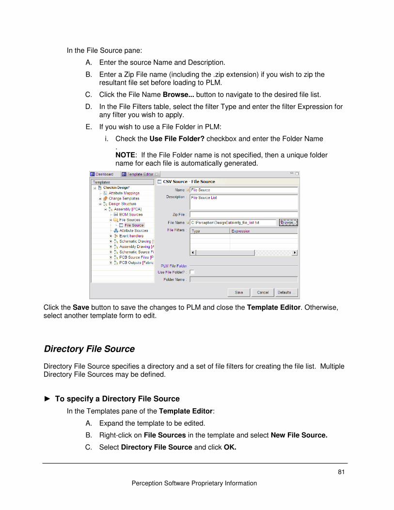
81
Perception Software Proprietary Information
In the File Source pane:
A. Enter the source Name and Description.
B. Enter a Zip File name (including the .zip extension) if you wish to zip the resultant file set before loading to PLM.
C. Click the File Name Browse... button to navigate to the desired file list.
D. In the File Filters table, select the filter Type and enter the filter Expression for any filter you wish to apply.
E. If you wish to use a File Folder in PLM:
i. Check the Use File Folder? checkbox and enter the Folder Name . NOTE: If the File Folder name is not specified, then a unique folder name for each file is automatically generated.
Click the Save button to save the changes to PLM and close the Template Editor. Otherwise, select another template form to edit.
Directory File Source Directory File Source specifies a directory and a set of file filters for creating the file list. Multiple Directory File Sources may be defined.
► To specify a Directory File Source
In the Templates pane of the Template Editor:
A. Expand the template to be edited.
B. Right-click on File Sources in the template and select New File Source.
C. Select Directory File Source and click OK.
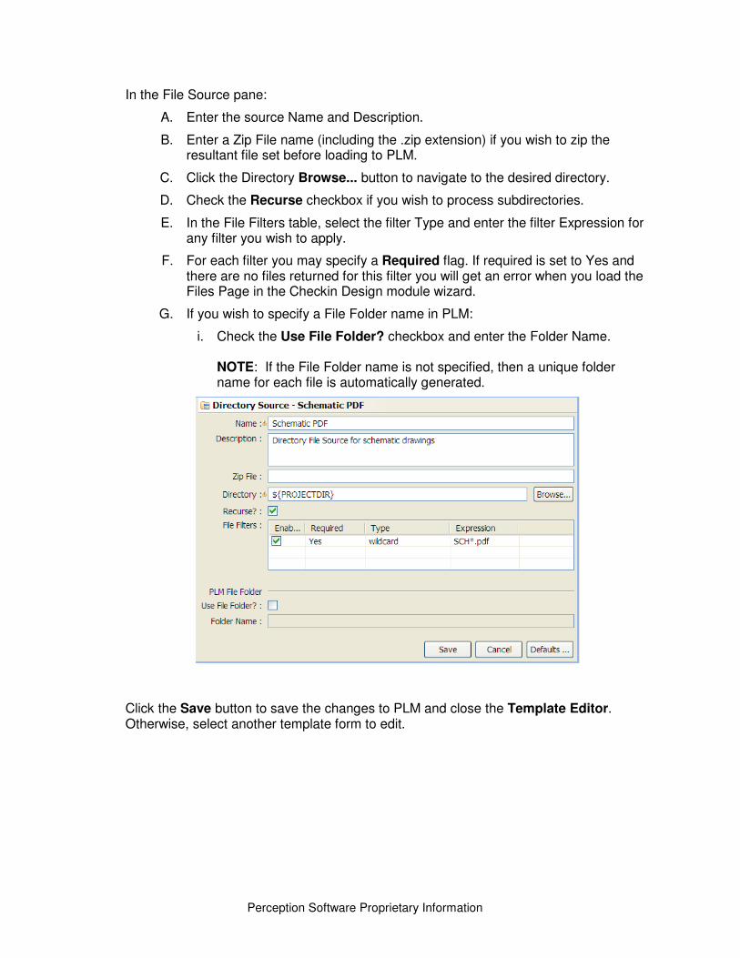
Perception Software Proprietary Information
In the File Source pane:
A. Enter the source Name and Description.
B. Enter a Zip File name (including the .zip extension) if you wish to zip the resultant file set before loading to PLM.
C. Click the Directory Browse... button to navigate to the desired directory.
D. Check the Recurse checkbox if you wish to process subdirectories.
E. In the File Filters table, select the filter Type and enter the filter Expression for any filter you wish to apply.
F. For each filter you may specify a Required flag. If required is set to Yes and there are no files returned for this filter you will get an error when you load the Files Page in the Checkin Design module wizard.
G. If you wish to specify a File Folder name in PLM:
i. Check the Use File Folder? checkbox and enter the Folder Name. NOTE: If the File Folder name is not specified, then a unique folder name for each file is automatically generated.
Click the Save button to save the changes to PLM and close the Template Editor. Otherwise, select another template form to edit.
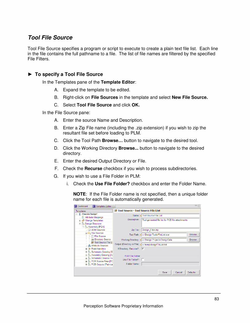
83
Perception Software Proprietary Information
Tool File Source Tool File Source specifies a program or script to execute to create a plain text file list. Each line in the file contains the full pathname to a file. The list of file names are filtered by the specified File Filters.
► To specify a Tool File Source
In the Templates pane of the Template Editor:
A. Expand the template to be edited.
B. Right-click on File Sources in the template and select New File Source.
C. Select Tool File Source and click OK.
In the File Source pane:
A. Enter the source Name and Description.
B. Enter a Zip File name (including the .zip extension) if you wish to zip the resultant file set before loading to PLM.
C. Click the Tool Path Browse… button to navigate to the desired tool.
D. Click the Working Directory Browse... button to navigate to the desired directory.
E. Enter the desired Output Directory or File.
F. Check the Recurse checkbox if you wish to process subdirectories.
G. If you wish to use a File Folder in PLM:
i. Check the Use File Folder? checkbox and enter the Folder Name. NOTE: If the File Folder name is not specified, then a unique folder name for each file is automatically generated.
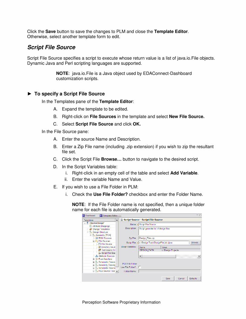
Perception Software Proprietary Information
Click the Save button to save the changes to PLM and close the Template Editor. Otherwise, select another template form to edit.
Script File Source Script File Source specifies a script to execute whose return value is a list of java.io.File objects. Dynamic Java and Perl scripting languages are supported.
NOTE: java.io.File is a Java object used by EDAConnect-Dashboard customization scripts.
► To specify a Script File Source
In the Templates pane of the Template Editor:
A. Expand the template to be edited.
B. Right-click on File Sources in the template and select New File Source.
C. Select Script File Source and click OK.
In the File Source pane:
A. Enter the source Name and Description.
B. Enter a Zip File name (including .zip extension) if you wish to zip the resultant file set.
C. Click the Script File Browse… button to navigate to the desired script.
D. In the Script Variables table:
i. Right-click in an empty cell of the table and select Add Variable.
ii. Enter the variable Name and Value.
E. If you wish to use a File Folder in PLM:
i. Check the Use File Folder? checkbox and enter the Folder Name. NOTE: If the File Folder name is not specified, then a unique folder name for each file is automatically generated.
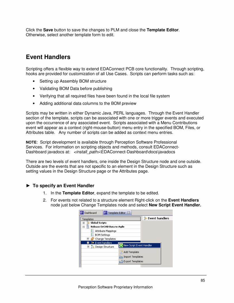
85
Perception Software Proprietary Information
Click the Save button to save the changes to PLM and close the Template Editor. Otherwise, select another template form to edit.
Event Handlers Scripting offers a flexible way to extend EDAConnect PCB core functionality. Through scripting, hooks are provided for customization of all Use Cases. Scripts can perform tasks such as:
• Setting up Assembly BOM structure
• Validating BOM Data before publishing
• Verifying that all required files have been found in the local file system
• Adding additional data columns to the BOM preview Scripts may be written in either Dynamic Java, PERL languages. Through the Event Handler section of the template, scripts can be associated with one or more trigger events and executed upon the occurrence of any associated event. Scripts associated with a Menu Contributions event will appear as a context (right-mouse-button) menu entry in the specified BOM, Files, or Attributes table. Any number of scripts can be added as context menu entries. NOTE: Script development is available through Perception Software Professional Services. For information on scripting objects and methods, consult EDAConnect-Dashboard javadocs at: <install_path>\EDAConnect-Dashboard\docs\javadocs There are two levels of event handlers, one inside the Design Structure node and one outside. Outside are the events that are not specific to an element in the Design Structure such as setting values in the Design Structure page or the Attributes page.
► To specify an Event Handler
1. In the Template Editor, expand the template to be edited.
2. For events not related to a structure element Right-click on the Event Handlers node just below Change Templates node and select New Script Event Handler.
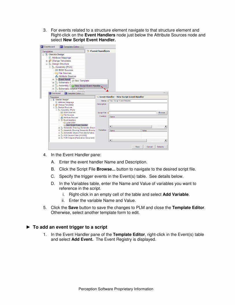
Perception Software Proprietary Information
3. For events related to a structure element navigate to that structure element and Right-click on the Event Handlers node just below the Attribute Sources node and select New Script Event Handler.
4. In the Event Handler pane:
A. Enter the event handler Name and Description.
B. Click the Script File Browse... button to navigate to the desired script file.
C. Specify the trigger events in the Event(s) table. See details below.
D. In the Variables table, enter the Name and Value of variables you want to reference in the script.
i. Right-click in an empty cell of the table and select Add Variable.
ii. Enter the variable Name and Value.
5. Click the Save button to save the changes to PLM and close the Template Editor. Otherwise, select another template form to edit.
► To add an event trigger to a script
1. In the Event Handler pane of the Template Editor, right-click in the Event(s) table and select Add Event. The Event Registry is displayed.
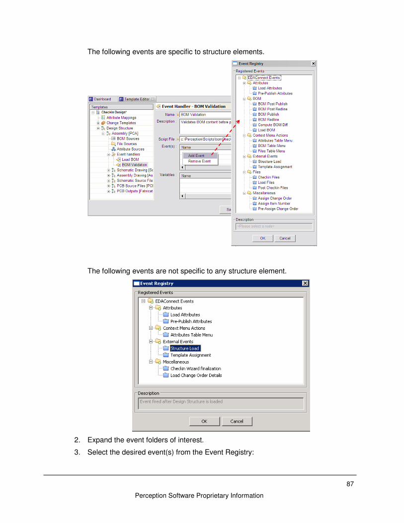
87
Perception Software Proprietary Information
The following events are specific to structure elements.
The following events are not specific to any structure element.
2. Expand the event folders of interest.
3. Select the desired event(s) from the Event Registry:
Perception Software Proprietary Information
A. Click on an event to select it.
B. Use Shift-click to select multiple, contiguous events.
C. Use Ctrl-click to select multiple, non-contiguous events.
D. Click the OK button to populate the Event(s) table.
► To delete an event trigger from a script
1. In the Event Handler pane of the Template Editor, select the row to be deleted in the Event(s) table.
2. Right-click in the Event(s) table and select Remove Event.
Problem Reporting If it appears that EDAConnect-Dashboard is not operating as expected and you require technical support assistance, you will need to report the problem to Perception Software. Please provide as much detail as possible about the error and send an email to [email protected] with the following information:
1. Company contact information
A. Name
B. Title
C. Phone number
D. Company name
E. Company location
2. Description of the problem
3. Steps to reproduce
4. EDAConnect-Dashboard Version and Build ID
5. Copy of the EDAConnect-Dashboard Log Window, if applicable
6. Screenshots and other additional files/information as appropriate A representative will review the issue and contact you to determine a course of action.
Information Gathering Providing the right information in a problem report is important. The following section describes where to find relative information.
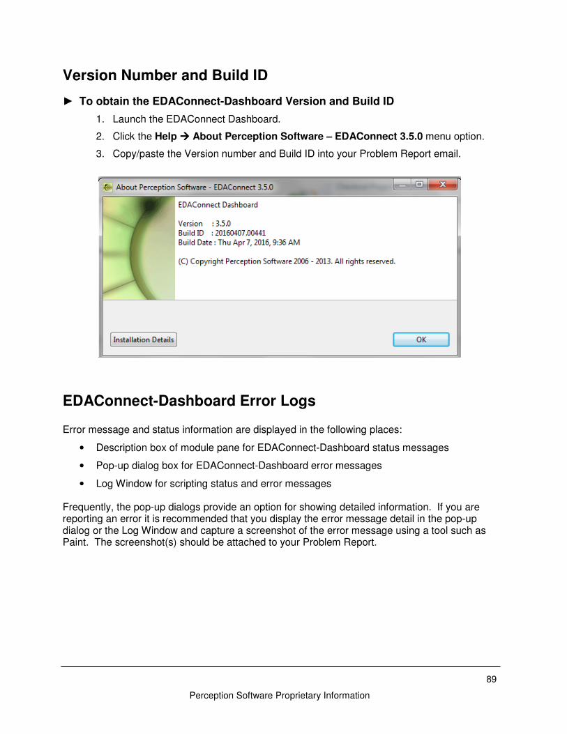
89
Perception Software Proprietary Information
Version Number and Build ID
► To obtain the EDAConnect-Dashboard Version and Build ID
1. Launch the EDAConnect Dashboard.
2. Click the Help ���� About Perception Software – EDAConnect 3.5.0 menu option.
3. Copy/paste the Version number and Build ID into your Problem Report email.
EDAConnect-Dashboard Error Logs Error message and status information are displayed in the following places:
• Description box of module pane for EDAConnect-Dashboard status messages
• Pop-up dialog box for EDAConnect-Dashboard error messages
• Log Window for scripting status and error messages Frequently, the pop-up dialogs provide an option for showing detailed information. If you are reporting an error it is recommended that you display the error message detail in the pop-up dialog or the Log Window and capture a screenshot of the error message using a tool such as Paint. The screenshot(s) should be attached to your Problem Report.


