003-126-AEN, Issue 6 STANDARD RECOMMENDED PROCEDURE 003-126-AEN | ISSUE 6 | JUNE 2018 | PAGE 1 OF 8 EDGE ™ LC-MTP ® Tap Module Installation and Testing related literature | Search www.corning.com/opcomm. Click on “Resources.” 003-794 EDGE ™ Solution Table of Contents 1. General .................................................... 1 2. Precautions ................................................................. 2 2.1 Laser Precautions ........................................................ 2 2.2 Cable Handling Precautions ................................................ 2 3. Tools and Materials ........................................................... 2 4. Connector and Adapter Cleaning ................................................ 2 5. Calculating System Loss Budgets ................................................ 3 6. The Functionality of the Tap Module Splitters ....................................... 5 7. Installing an EDGE™ LC-MTP Tap Module ......................................... 5 8. Referencing the Test Equipment for an LC-MTP Tap Module . . . . . . . . . . . . . . . . . . . . . . . . . . . 5 9. Testing EDGE LC-MTP Tap Modules ............................................. 7 1. General 1.1 This procedure describes EDGE™ LC-MTP Tap Modules, which are available for both multimode and single mode applications. Compatible with all EDGE rack-mountable connector housings, LC-MTP Tap modules have twelve front-mounted shuttered LC adapters and two rear-mounted MTP connectors (Figure 1). 1.2 The module contains 12 fiber optic splitters which divide the incoming optical signals into two outputs, one for live link traffic and one for monitoring. The monitor traffic is routed via the “TAP”-labeled MTP connector to a monitoring device which filters the data and sends it to various software tools for analysis, where it is then viewed in application-layer software for security threats, performance issues, or system optimization. IMPORTANT: Please note that Tap module systems have two outputs for each input, which may require two power meters, and depending on the system configuration, possibly require an additional craftsperson in another location. Live Tap TPA-6112 Figure 1
Transcript
003-126-AEN, Issue 6
STANDARD RECOMMENDED PROCEDURE 003-126-AEN | ISSUE 6 | JUNE 2018 | PAGE 1 OF 8
EDGE™ LC-MTP® Tap Module Installation and Testing
related literature | Search www.corning.com/opcomm. Click on “Resources.”003-794 EDGE™ Solution
1. General1.1 This procedure describes EDGE™ LC-MTP
Tap Modules, which are available for both multimode and single mode applications. Compatible with all EDGE rack-mountable connector housings, LC-MTP Tap modules have twelve front-mounted shuttered LC adapters and two rear-mounted MTP connectors (Figure 1).
1.2 The module contains 12 fiber optic splitters which divide the incoming optical signals into two outputs, one for live link traffic and one for monitoring. The monitor traffic is routed via the “TAP”-labeled MTP connector to a monitoring device which filters the data and sends it to various software tools for analysis, where it is then viewed in application-layer software for security threats, performance issues, or system optimization.
IMPORTANT: Please note that Tap module systems have two outputs for each input, which may require two power meters, and depending on the system configuration, possibly require an additional craftsperson in another location.
Live
Tap
TPA-6112
Figure 1
STANDARD RECOMMENDED PROCEDURE 003-126-AEN | ISSUE 6 | JUNE 2018 | PAGE 2 OF 8
2. Precautions2.1 Laser Precautions
WARNING: DO NOT use magnifiers in the presence of laser radiation. Diffused laser light can cause eye damage if focused with optical instruments. Should accidental eye exposure to laser light be suspected, arrange for an eye examination immediately.
2.2 Cable Handling PrecautionsCAUTION: Fiber optic cable is sensitive to excessive pulling, bending, and crushing forces. Consult the cable specification sheet for the cable you are installing. Do not bend the cable more sharply than the minimum recommended bend radius. Do not apply more pulling force to the cable than specified. Do not crush the cable or allow it to kink. Doing so may cause damage that can alter the transmission characteristics of the cable; the cable may have to be replaced.
3. Tools and Materials3.1 The following tools and materials are required for this procedure:
• Power meters with LC port adapters (2)• LC-LC jumpers (2)• SC-LC jumper for the light source (1)• LC-LC adapter (1)• Light source• MTP to LC harness (1)• LC port cleaner (p/n CLEANER-PORT-LC)• MTP Connector and port cleaning tool (p/n 2104466-01)
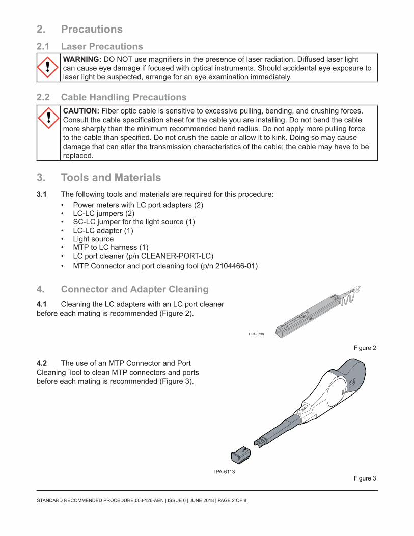
4. Connector and Adapter Cleaning 4.1 Cleaning the LC adapters with an LC port cleaner before each mating is recommended (Figure 2).
Figure 2
4.2 The use of an MTP Connector and Port Cleaning Tool to clean MTP connectors and ports before each mating is recommended (Figure 3).
Figure 3
HPA-0738
TPA-6113
STANDARD RECOMMENDED PROCEDURE 003-126-AEN | ISSUE 6 | JUNE 2018 | PAGE 3 OF 8
5. Calculating System Loss Budgets5.1 This section describes how to calculate the loss budgets of a system using an EDGE™ Tap
Module. Note that you will need to calculate one loss budget for the LIVE system (Figure 4) and two different loss budgets for the Tap output (Figure 5 and 6).
Table 1 indicates the system loss values of the system components:
Table 1: System Loss Values
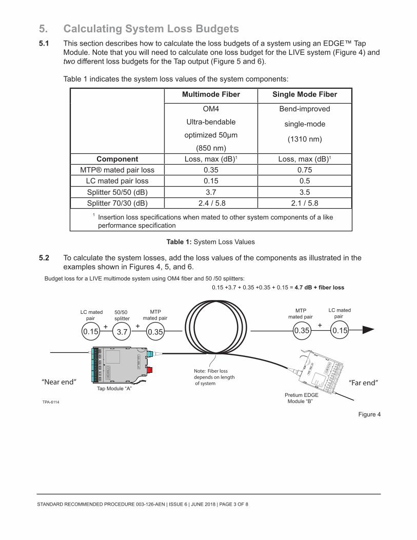
5.2 To calculate the system losses, add the loss values of the components as illustrated in the examples shown in Figures 4, 5, and 6.
1 Insertion loss specifications when mated to other system components of a like performance specification
Tap Module “A”Pretium EDGE Module “B”TPA-6114
“Near end” “Far end”
Budget loss for a LIVE multimode system using OM4 fiber and 50 /50 splitters:
0.15 0.35 0.353.7 0.15+ + +
LC mated pair
LC mated pair
50/50 splitter
MTP mated pair
MTP mated pair
0.15 +3.7 + 0.35 +0.35 + 0.15 = 4.7 dB + fiber loss
Note: Fiber lossdepends on length of system
B
612
11
A
B
510
9
A
B
48
7
A
B
36
PnP
Mod
ule
Part
Num
ber
Seria
lM
ADE
IN M
EXIC
O
5
A
B
24
3
A
B
12
1
A
WAR
RANTY
VOID
BA
LIV
ELi
veTa
p
STANDARD RECOMMENDED PROCEDURE 003-126-AEN | ISSUE 6 | JUNE 2018 | PAGE 4 OF 8
Figure 5
Figure 6
Tap port test harness
Tap Module “A”
TPA-6115
“Near end”
Budget loss for a “Near end” Tap port test harness multimode system using OM4 fiber and 50 /50 splitters:
0.15
0.35
3.7
0.15
++
+
LC mated pair
LC mated pair
50/50 splitter
MTP mated pair
0.15 +3.7 + 0.35 + 0.15 = 4.35 dB + fiber loss
Note: Fiber lossdepends on length of system
BA
LIV
ELi
veTa
p
Tap Module “A”EDGE™ Module “B”
TPA-6116
“Far end”“Near end”
Budget loss for a “Far end” to Tap Port harness multimode system using OM4 fiber and 50 /50 splitters:
0.35 0.35
0.35
3.7 0.15
0.15
+
+
+
+ +
LC mated pair
LC mated pair
50/50 splitter
MTP mated pair
MTP mated pair
MTP mated pair
Tap port test harness
0.15 +3.7 + 0.35 + 0.35 + .035 + 0.15 = 5.05 dB + fiber loss
B
612
11
A
B
510
9
A
B
48
7
A
B
36
PnP
Mod
ule
Part
Num
ber
Seria
lM
ADE
IN M
EXIC
O
5
A
B
24
3
A
B
12
1
A
WAR
RANTY
VOID
Note: Fiber lossdepends on length of system
BA
LIV
ELi
veTa
p
STANDARD RECOMMENDED PROCEDURE 003-126-AEN | ISSUE 6 | JUNE 2018 | PAGE 5 OF 8
6. The Functionality of the Tap Module SplittersDirectionality
6.1 In simplest terms, the splitters inside a Tap module act like a divider of a one-way traffic flow – in this case, light.
The even-numbered LC connectors in a Tap module serve only for source input and their traffic is split between the LIVE and TAP outputs (Figure 7, top).In the same fashion, the Tap module’s odd-numbered LC connectors receive live traffic from the LIVE MTP input port. The input traffic from the LIVE input port is split between the LIVE LC odd fibers and the MTP TAP port (Figure 7, bottom).
Tables 2 and 3 in Section 9 provide a full representation of the source and output positions
6.2 Tap modules therefore must be tested with directionality in mind. The source must be always connected to the input of the splitter and the meter must be connected to the output of the splitter. Connecting a source to the output of a splitter will result in high attenuation.
Wavelength Considerations
6.3 The splitters on multimode modules are optimized for 850 nm VCSEL (Vertical-cavity Surface-emitting Lasers), thus when testing multimode systems, use only the 850 nm wavelength.
6.4 Single mode systems may be tested at both 1310 and 1550 nm.
7. Installing an EDGE™ LC-MTP Tap ModuleNOTE: EDGE Tap modules are installed just like their normal EDGE module counterparts. Refer to the
Installation chapter in SRP-003-794, EDGE Solution, for complete instructions. This procedure covers module installation, trouble shooting, and other module-related topics as well.
Install the Tap module and its Tap MTP harness into your system housing.
8. Referencing the Test Equipment for an LC-MTP Tap Module NOTE: If using Fluke DTX tester, testing live-to-tap-out, use REMOTE END SETUP (FAR END
SOURCE). Refer to “How to Use the DTX-MFM2 Fiber Modules to Test Installed Corning Multimode EDGE™ Tap Modules,” at http://www.flukenetworks.com/findit/en-us/9830231.
8.1 Start by powering on the source and meter and allowing a minimum of 5 minutes for them to warm up and stabilize.
For multimode systems: set the unit to the 850 nm wavelength.
For single mode systems: Set the unit to auto-switch between 1310 and 1550 nm wavelengths.
BA
LIV
ELi
veTa
p
B
6 1211
AB 5 10
9
AB
48
7
AB
3 65
AB
2 43
AB
1 21
A
Input into LC # 2
Live outputfromLC # 1
LIVEoutput
TPA-6117
Tap outputon MTP �ber 1
TAPoutput
TAPoutput
BA
LIV
ELi
veTa
p
B
6 1211
AB 5 10
9
AB
48
7
AB
36
5
AB
2 43
AB
1 21
A
LIVEsource
Tap outputon MTP �ber 2
Figure 7
STANDARD RECOMMENDED PROCEDURE 003-126-AEN | ISSUE 6 | JUNE 2018 | PAGE 6 OF 8
8.2 To reference the source and two meters:
Step 1: Clean and insert the SC-end of the SC to LC jumper (Reference Jumper no. 1, or RJ1) into the output of the light source.
Step 2: Clean and insert the LC end of RJ1 jumper into the LC port adapter of Meter no. 1 (M1) (Figure 8).
For multimode only: Wrap the jumper 5 times and secure it in a 25 mm mandrel with tape (standard 50 µm multimode procedure).Step 3: Verify that RJ1 is acceptable at
your system’s wavelength(s) and reference this power to 0.00 dB. Step 4: Disconnect and move the meter-end LC of RJ1 to Meter no. 2 (M2) and repeat
Step 3. Disconnect M2 after this step.Step 5: Clean and insert the LC end of RJ1 into an LC adapter.
Step 6: Clean and install an LC to LC jumper-Reference Jumper no. 2 (RJ2) into M1 and the LC adapter (Figure 9).
Step 7: Verify that the RJ1/ RJ2 mated pair are acceptable with a loss ≤0.15 dB.
Step 8: Disconnect RJ2’s LC connector from the LC adapter and protect it with a clean dust cap until you are ready to start the system testing.
Step 9: Clean and install an LC to LC jumper-Reference Jumper no.3 (RJ3) into M2 and the LC adapter (Figure 10).
Step 10: Verify that the RJ1/RJ3 mated pair are acceptable with a loss ≤0.15 dB.
Step 11: Disconnect RJ1’s LC connector from the LC adapter and protect it with a clean dust cap.
Step 12: Leave the LC adapter on the end of RJ3 for the remainder of this procedure since it will be required for mating to the TAP port test harness.
Light Source (Tx)
Do NOT disconnect
HPA-0758
Meter no. 1 (RX)
Meter no. 2 (RX) M2
0.00
Launch Conditioner for multimode only
Reference Jumper no.1 RJ1
M1
Figure 8
Do NOT disconnect
Do NOT disconnect
HPA-0759
LC adapter
0.15 dB
multimode only
RJ1 Reference Jumper no. 2 RJ2
M1 Light Source
Figure 9
Do NOT disconnect
Light Source
M1
HPA-0760
LC adapter
Dust cap
RJ2 Do NOT disconnect
0.3 dB
multimode only
RJ 1
RJ3
M2
0.15 dB
Figure 10
STANDARD RECOMMENDED PROCEDURE 003-126-AEN | ISSUE 6 | JUNE 2018 | PAGE 7 OF 8
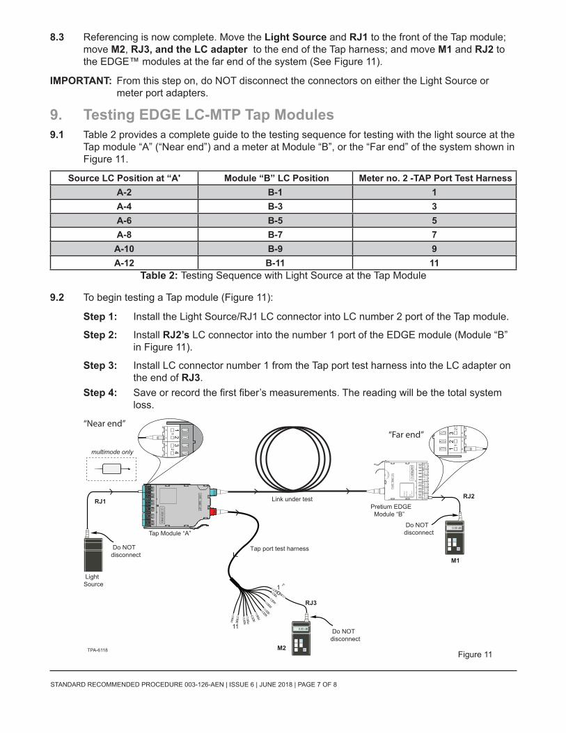
8.3 Referencing is now complete. Move the Light Source and RJ1 to the front of the Tap module; move M2, RJ3, and the LC adapter to the end of the Tap harness; and move M1 and RJ2 to the EDGE™ modules at the far end of the system (See Figure 11).
IMPORTANT: From this step on, do NOT disconnect the connectors on either the Light Source or meter port adapters.
9. Testing EDGE LC-MTP Tap Modules9.1 Table 2 provides a complete guide to the testing sequence for testing with the light source at the
Tap module “A” (“Near end”) and a meter at Module “B”, or the “Far end” of the system shown in Figure 11.
Source LC Position at “A' Module “B” LC Position Meter no. 2 -TAP Port Test HarnessA-2 B-1 1A-4 B-3 3A-6 B-5 5A-8 B-7 7A-10 B-9 9A-12 B-11 11
Table 2: Testing Sequence with Light Source at the Tap Module
9.2 To begin testing a Tap module (Figure 11):
Step 1: Install the Light Source/RJ1 LC connector into LC number 2 port of the Tap module.
Step 2: Install RJ2’s LC connector into the number 1 port of the EDGE module (Module “B” in Figure 11).
Step 3: Install LC connector number 1 from the Tap port test harness into the LC adapter on the end of RJ3.
Step 4: Save or record the first fiber’s measurements. The reading will be the total system loss.
Light Source
Tap port test harness
Link under test
M1
M2
RJ2 RJ1
Do NOT disconnect
Do NOT disconnect
0.00 dB
0.00 dB
Tap Module “A”
Pretium EDGE Module “B”
B
23
B
12
1
A
B
2 43
AB
1 21
A
11
1
TPA-6118
multimode only
Do NOT disconnect
RJ3
“Near end”“Far end”
B
61211
AB
5109
AB
48
7
AB
36
PnP
Mod
ule
Par
t Num
ber
Ser
ial
MA
DE
IN M
EX
ICO
5
AB
24
3
AB
12
1
A
WAR
RAN
TY
VO
ID
BA
LIV
ELi
veTa
p
B
6 1211
AB 5 10
9
AB
48
7
AB
3 65
AB
2 43
AB
1 21
A
Figure 11
STANDARD RECOMMENDED PROCEDURE 003-126-AEN | ISSUE 6 | JUNE 2018 | PAGE 8 OF 8
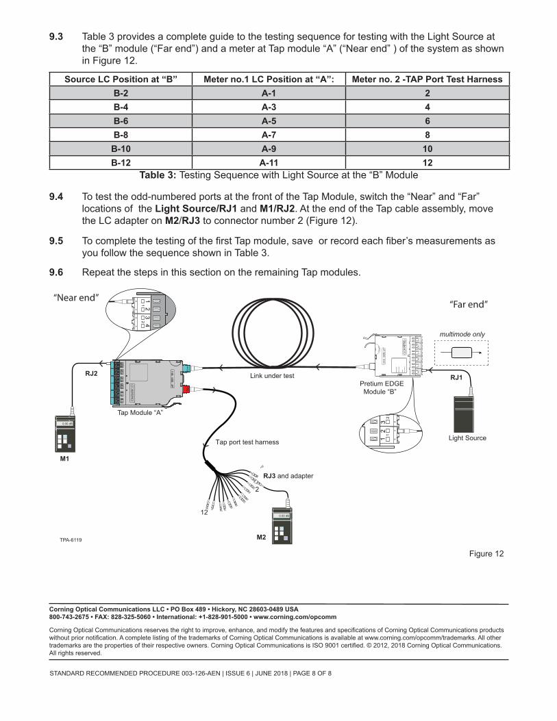
9.3 Table 3 provides a complete guide to the testing sequence for testing with the Light Source at the “B” module (“Far end”) and a meter at Tap module “A” (“Near end” ) of the system as shown in Figure 12.
Source LC Position at “B” Meter no.1 LC Position at “A”: Meter no. 2 -TAP Port Test HarnessB-2 A-1 2B-4 A-3 4B-6 A-5 6B-8 A-7 8B-10 A-9 10B-12 A-11 12
Table 3: Testing Sequence with Light Source at the “B” Module
9.4 To test the odd-numbered ports at the front of the Tap Module, switch the “Near” and “Far” locations of the Light Source/RJ1 and M1/RJ2. At the end of the Tap cable assembly, move the LC adapter on M2/RJ3 to connector number 2 (Figure 12).
9.5 To complete the testing of the first Tap module, save or record each fiber’s measurements as you follow the sequence shown in Table 3.
9.6 Repeat the steps in this section on the remaining Tap modules.