45
EDICON 2019 Active Modulated Load Pull Dr. Sajjad Ahmed Business Development Manager

EDICON 2019
Active Modulated Load PullDr. Sajjad Ahmed
Business Development Manager

About Us
2
Focus Microwaves is a pioneering engineering company, builtaround the innovations of its founder Dr. Christos Tsironis, whodeveloped his first manual tuner in 1973, and is the inventor ofmost existing electro-mechanical tuner families; and theengineering and manufacturing skill of its highly motivated andexperienced team of Technicians and Engineers, who have beentrained and encouraged to develop new technologies and listento and support our customers. Starting in 1988, Focus hasmeanwhile become the main supplier of advanced Load Pull andNoise tuner systems.
FOCUS MICROWAVES

3
OUR OFFICES AROUND THE WORLD
3

Outline
4
• Load-pull Measurement Basics• Scalar Load-pull
• Vector Load-pull
• Hybrid Load-pull
• Active Load-pull
• Wave based Load-pull to Behavioural Model
• RAPID Measurement Setup• Comparisons of RAPID and traditional LP
• Effects of modulation BW
• RAPID Load-pull System Description• System Architecture
• Vector Calibration
• Active Loop Calibration
• RAPID CW Measurements and Comparison with Traditional LP Setups
• RAPID Modulated Load-pull Measurements
• Conclusions

Load Pull Basics
55

Introduction to Load-Pull
6
Load Pull
• An accurate measurement of key nonlinear performance parameters, including output power, gain, efficiency, linearity, etc. as a function of the fundamental load impedance, which is the key design parameter is typically referred to as load-pull.
Load Pull procedure consists of:
• Assessing the performance of the DUT qualitatively under differentimpedances
• Establishing a condition under which optimal performance can beobtained
Why Load and Source Pull ?
• Design, optimize RF/µW power amplifiers & transistors• Design matching networks of transistors• Develop a semiconductor process• Synthesize impedances in Smith Chart
What is Load-Pull
Source
Zo
ΓsΓout
ΓIN ΓL
Source Plane Load Plane
Source Tuner Load
Harmonic Tuner
a1 b2
a2b1
Load-Pull Contours

Load Pull Measurements
7
• Impedance control is provided by a passive tuner or an active tuner.
• An impedance tuner generates controllable reflection factor (Impedance) over acertain frequency range.
The movement of a stub/probe/slug in the vertical
direction changes the magnitude of the reflection
factor
The movement of a stub/probe/slug in the horizontal
direction alters the phase of the reflection factor

Load Pull setups -Scalar Load Pull
8
The typical scalar load pull setup comprises a signal generator, a power divider, two RF power sensors, a power meter, some DC bias networks and two fundamental tuners.
Measurements include:• Pin, Pout, Gaintrd, ACPR,• ΓLoad, Γsource

Load Pull setups – Vector Load Pull
9
Vector Load Pull allows measuring the input and output large signal impedances of the DUT, the input delivered power, the Power added efficiency, and the real time incident and reflected waves thus not relying on mechanical tuner repeatability
Measurements include:• Pin, Pout, Gaintrd ,Gainpwr
• PAE, ACPR• ΓLoad, ΓIN
Major advantage:• Speed • Higher dynamic range• Time domain Waveform

Load Pull setups – Hybrid Load Pull
10
As per its name a hybrid load pull system includes both an active loop as well as the passive tuners. The hybrid system has all the advantages of speed and tuning range of an active system as well as the power handling of a passive system.
Measurements include:• Pin, Pout, Gain, PAE, ACPR• Gamma In/Out DUT• Gamma >1
The tuning algorithm finds the optimum compromise for tuner loss and Pinj for reaching Γload.
Active Load Pull – Basic Principal
11
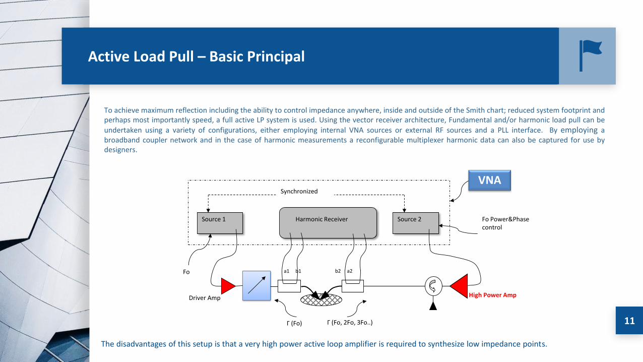
To achieve maximum reflection including the ability to control impedance anywhere, inside and outside of the Smith chart; reduced system footprint andperhaps most importantly speed, a full active LP system is used. Using the vector receiver architecture, Fundamental and/or harmonic load pull can be
undertaken using a variety of configurations, either employing internal VNA sources or external RF sources and a PLL interface. By employing abroadband coupler network and in the case of harmonic measurements a reconfigurable multiplexer harmonic data can also be captured for use bydesigners.
Γ (Fo, 2Fo, 3Fo..)
Synchro
Driver Amp
Source 1 Source 2Harmonic Receiver
VNA
High Power Amp
Γ (Fo)
a1 b1 b2 a2Fo
Fo Power&Phase control
Synchronized
The disadvantages of this setup is that a very high power active loop amplifier is required to synthesize low impedance points.

Introduction to RAPID
1212

Load Pull Setups - RAPID
13
Key Benefits
Dramatically improve Test-Bench Throughput
• Ultra-fast impedance control and measurement (up to 50 Measurements/Second including DC)
Improved Modulated Measurement Capability
• 100MHz real time bandwidth with wideband impedance control and/or circuit emulation
• Ability to de-skew non-ideal tuner impedance over bandwidth
Reduced Test-Bench CAPEX
• Self Calibrating – No VNA required
• Real-Time power measurements
• Real-Time Spectral/Vector measurements
• No Spectrum Analyzer
RAPID Load Pull

RAPID vs Traditional LP
14

Active – Passive Load Pull
15
RAPID Load Pull Passive Load Pull

Modulation Load Pull
16
Modulation bandwidth comparison Impedance Skew

RAPID LP System Description
1717

Active Load Pull
18
• The Rapid Load-pull system is a programmable digital, PXI-based, feedback active load-pull tuner that maximizes throughput of a load-pull bench.
• The input and output port of the DUT are fed via a dual-directional couplers to a down converter module. • The baseband data is then processed in an FPGA module and sent to the up converter to form the injected signal.

RAPID Modular Architecture
19
1 Frequency Fundamental Diagram 1 Frequency Fundamental Setup

RAPID Modular Architecture
20
2 Frequency Diagram 2 Frequency Setup

RAPID Modular Architecture
21
3 Frequency Diagram 3 Frequency Setup

RAPID Hardware Architecture
22
• The RAPID series of tuners leverages the performance and reliability ofNational Instrument RF/uW hardware. For basic CW testing, the RAPIDseries of tuners requires at minimum a PXI chassis (with 10MHz timing), areal-time FPGA and Extension card.
• Functionalities like RF pulsed, advanced carrier modulation and DCmeasurements can be added to the system by simply adding the desiredPXI module to the PXI Chassis. This makes the system modular and easilyupgradable

S-Parameter & Power Calibration
23
• The system can measure the forward and reversetravelling waves, so unlike a passive tuner calibration,there is no requirement for an external VNA.
• The first step is therefore to perform a one or two portVNA calibration, this is performed as a standard SOL,SOLT, or TRL cal at the desired reference plane.
• A power meter can then be used to calibrate foraccurate power measurements, by attaching a powermeter to the reference plane.

Rapid Active Loop Calibration
24
• The loop calibration must be performed beforeattaching the device.
• It is used to calculate the error coefficients associatedwith the feedback loop.
• Once these error coefficients have been found the usercan accurately set any impedance on the smith chartwithout the need for interpolation.

CW Signal Measurements
2525

CW – Active Loop Calibration
26

CW – Impedance Synthesis Verification
27

Long Term Stability
28
D E V I C E T E S T I N G
L o n g T e r m S t a b i l i t y
Average Repeatability 66.45dB
• Test conducted with a DUT present
• Power and impedance were swept for a65 hour period.
• Desired tolerance is set to 50dB.
Load Pull Pattern
After 65 HrsStart of Test

CW Measurement Comparison
29
Power Contours & Swept Power
* note that passive tuner cannot quite reach the edge of the desired 5 ohm circle, but active can overcome this issue.
Passive Load-Pull
RAPID Load-Pull
Power Sweep Measurements

Measurement Comparison
30
Passive Load Pull RAPID Active Load Pull
Excellent agreement in measured contours
between two systems30

Modulated Signal Measurements
3131

Modulated – Active Loop Calibration
32

Modulated – Verification
33
Example 20MHz LTE Pattern Verification

Modulated – Verification
34
Example 2x20MHz LTE Pattern Verification
Modulated - Measurements
35
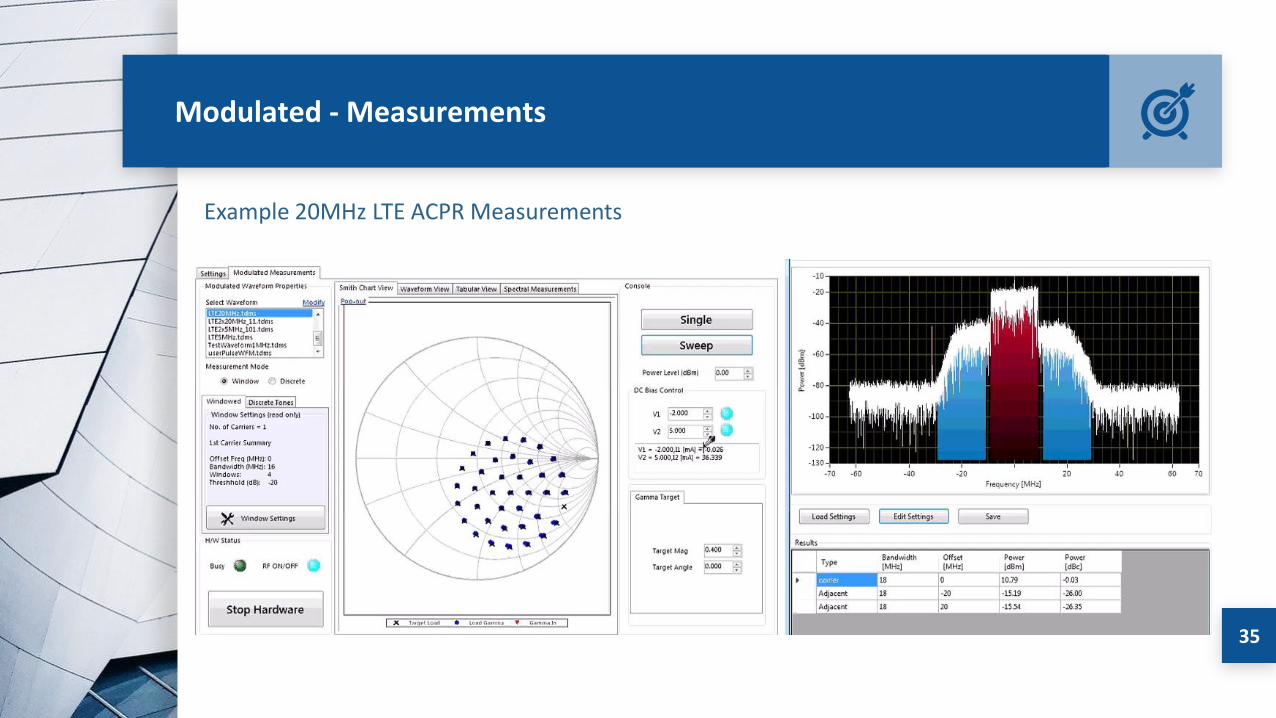
Example 20MHz LTE ACPR Measurements

ACPR- Comparison RAPID and Passive LP setups
36
*Passive measurement result contours are somewhat “noisy”. This can be reduced by averaging
or by reducing resolution bandwidth of the signal analyser which increases measurement time.
Passive system Rapid system
ACPR_low with 1 dB compressed peaks

ACPR- Comparison RAPID and Passive LP setups
37
*Passive measurement result contours are somewhat “noisy”. This can be reduced by averaging
or by reducing resolution bandwidth of the signal analyser which increases measurement time.
Passive system Rapid system
ACPR_low with 1 dB compressed peaks

Digital Predistortion
38
Digital Predistortion
• The system hardware is implementedwithin an NI PXI vector signaltransceiver (VST).
• This VST is able to support up to 1 GHzsignal bandwidth up to a maximumoperational frequency of 6 GHz.
• The proprietary DPD algorithm isimplemented in a NI software packagecalled RFIC.

Digital Predistortion under Non 50Ω
39
Digital Predistortion & LP Applied Simultaneously
• Both systems utilize PXI chassis-basedcomponents.
• All of the RLP and DPD software iscontrolled using the in-chassiscontroller.
• Fast PCI based backplane provides theability to stream and process data toand from both the RLP and DPDsystems.
• Real Time Analysis• AM-AM• AM-PM• ACPR

Digital Predistortion
40
The measurements of a 2W GaN HEMT without DPD
ΓOPT= 0.464Φ159.4

Digital Predistortion
41
ΓOPT= 0.764Φ179 ΓOPT= 0.475Φ157
-40.219dbc -41.85dbc

Digital Predistortion under Non 50Ω
42ΓOPT= 0.473Φ153.4
Pout
The measurements of a 2W GaN HEMT with DPD

Digital Predistortion under Non 50Ω
43
ΓOPT= 0.478Φ157 ΓOPT= 0.475Φ157
-47.9dbc-47.9dbc
ACPR-Low ACPR-High

Digital Predistortion under Non 50Ω
44
• The measurements of a 10W GaN HEMT device have highlighted a large difference incontours with and without DPD.
• Without DPD the Pout and ACPR contours have different optimum impedances.
• With DPD applied both Pout and ACPR contours have aligned hence yielding max Poutand max linearity at same optimum impedance
• The measurements demonstrate that this system combination can be used as avaluable tool in RFPA design to fully characterize the device under realistic modulatedand impedance conditions
Conclusion
45
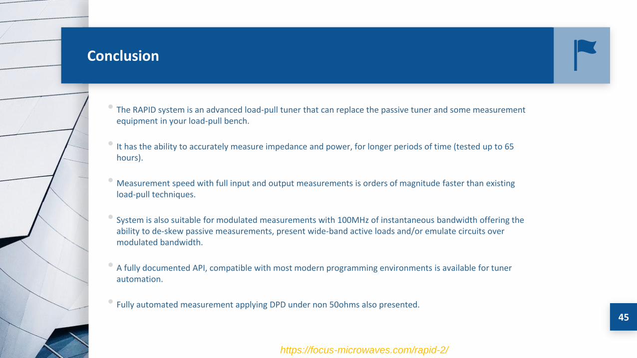
• The RAPID system is an advanced load-pull tuner that can replace the passive tuner and some measurement equipment in your load-pull bench.
• It has the ability to accurately measure impedance and power, for longer periods of time (tested up to 65 hours).
• Measurement speed with full input and output measurements is orders of magnitude faster than existing load-pull techniques.
• System is also suitable for modulated measurements with 100MHz of instantaneous bandwidth offering the ability to de-skew passive measurements, present wide-band active loads and/or emulate circuits over modulated bandwidth.
• A fully documented API, compatible with most modern programming environments is available for tuner automation.
• Fully automated measurement applying DPD under non 50ohms also presented.
https://focus-microwaves.com/rapid-2/


