40
EDITION 1 2008 Welding products

EDITION 1 2008
Welding products

GCE Group GCE world-wide: http://www.gcegroup.com
Founded in 1978, GCE is now one of the world’s leading manufacturers of gas equipment, employing over 1,000 people in its production facilities in Europe and Asia.
The company has grown through a combination of a dedicated workforce and an in depth knowledge of pressure and flow control, able to support customers in their demands
for safe and reliable products at competitive prices.

Content
1
Welding / Cutting blowpipes - Orbit lightweightWelding / Cutting blowpipes - Orbit CaddypakWelding / Cutting blowpipes - MK 3/4/5 medium dutyCutters - Universal / SteelmasterPropane/air heating equipmentNozzles - cuttingNozzles - welding and heatingRegulators - single stageRegulators - refrigerationRegulators - balloon inflatorsRegulators - medicalRegulators - multistageRegulators - special purposeFlashback arrestors and hose check valvesCutting machinesHose - bulk unfittedHose - fitted supplied with hose check valvesHose fittingsManifolds - outlet pointsManifolds - single cylinder couplers and racksManifolds - adaptors and fittingsManifolds - high pressure flexiblesValves - low pressureValves - high pressureData charts and safety precautions
24579
1214161616171819212325262830313233343536
Section Page

WELDING
CUTTING
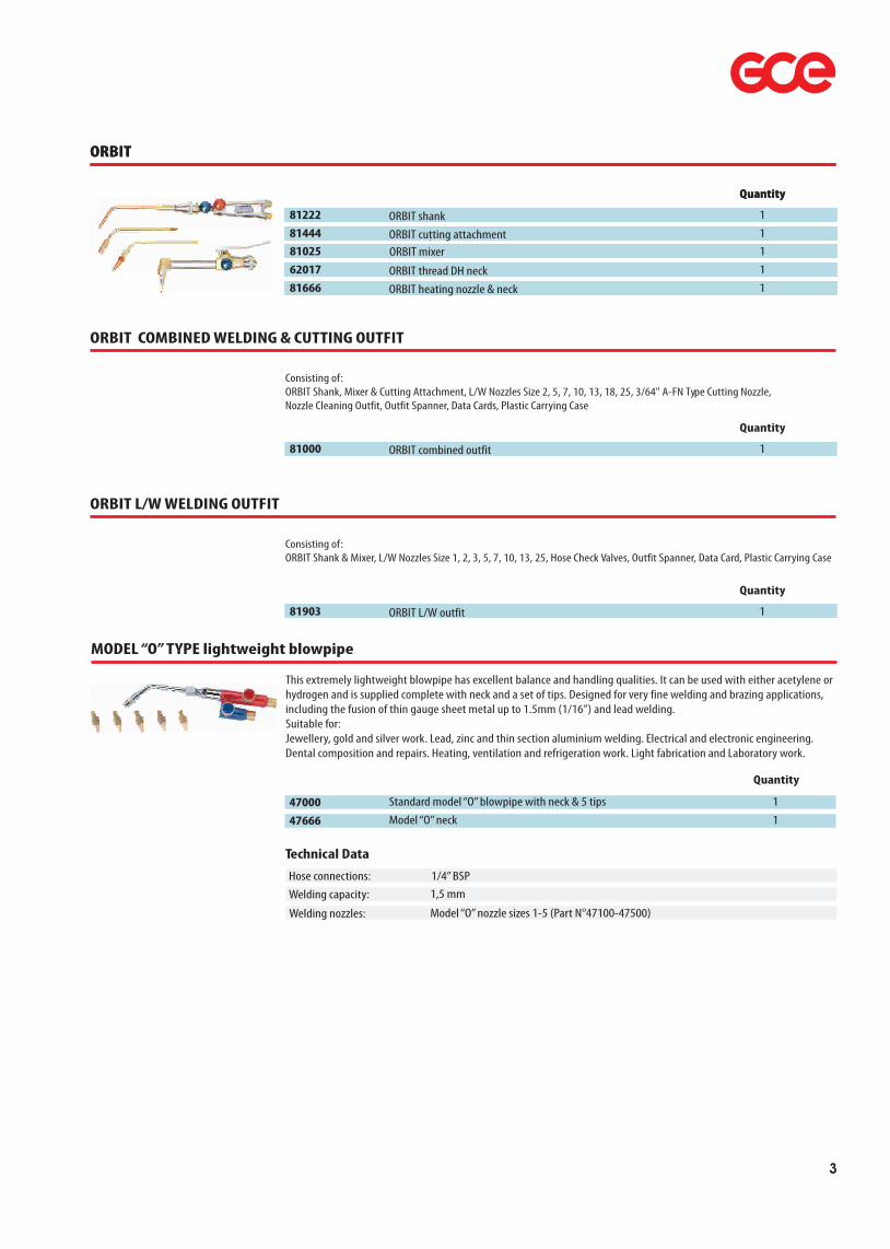
The shank can be used with either lightweight swagednozzles or D.H. solid copper tips + brass neck accordingto the operators preference, enabling precise flamecontrol and up to 8mm (5/16") welding capacity in steel.
The newly designed lightweight cutting attachment usesthe nozzle mix principle and is thus highly resistant tobackfire and flashback. Although of a lightweight design,it is engineered from solid brass castings and silversoldered tubes to provide an extremely robustconstruction. Using Orbit A-FN type nozzles andAcetylene fuel gas the orbit has a cutting capacity ofover 20mm.BUTBRO torches and nozzles conform to BS EN ISO 5172
HOSE CONNECTIONS - 1/4" BSP (Other threads available on request)WELDING CAPACITY - 8mmCUTTING CAPACITY - 20mmWELDING NOZZLES - Lightweight, Swaged Nozzles Size 1-25 D.H. Solid Copper Tips Sizes 1-25CUTTING NOZZLES - ORBIT A-FN Cutting Nozzles ORBIT A-SFN Sheet Metal Nozzles (Full Details of nozzles on page 13/14/15)
A new superbly constructed welding & cutting blowpipedesigned with safety in mind and engineered fromhighest quality materials to complement the operator inproduction or light gauge maintenance welding & cutting.The shank is common to both welding and cutting heads,the same quick, positive and leak-free means of attachmentbeing used for both. The shank is manufactured from asolid drilled aluminium forging thus avoiding the necessityof internal tubes and giving added safety.
ORBIT COMBINED WELDING & CUTTING OUTFIT 81000ORBIT L/W WELDING OUTFIT 81903
81666
62017
2
81000
81903
”Lightweight welding & cutting blowpipeORBIT”
ORBIT
Quantity
WP14011 Visual Flame DIN5 1
WP14064 Visual Flip DIN5 1
81222 ORBIT shank 1
81444 ORBIT cutting attachment 1 1
1
81025 ORBIT mixer 1
81026 ORBIT thread d.h. neck 1
1 81666 ORBIT heating nozzle & neck 1
ORBIT
Quantity
WP14011 Visual Flame DIN5 1
WP14064 Visual Flip DIN5 1
81222 ORBIT shank 1
81444 ORBIT cutting attachment 1 1
1
81025 ORBIT mixer 1
62017 ORBIT thread DH neck 1
1 81666 ORBIT heating nozzle & neck 1
ORBIT COMBINED WELDING & CUTTING OUTFIT
Quantity
WP14011 Visual Flame DIN5 1 81000 ORBIT combined outfit 1
Consisting of:ORBIT Shank, Mixer & Cutting Attachment, L/W Nozzles Size 2, 5, 7, 10, 13, 18, 25, 3/64" A-FN Type Cutting Nozzle,Nozzle Cleaning Outfit, Outfit Spanner, Data Cards, Plastic Carrying Case
ORBIT L/W WELDING OUTFIT
Quantity
WP14011 Visual Flame DIN5 1 81903 ORBIT L/W outfit 1
Consisting of:ORBIT Shank & Mixer, L/W Nozzles Size 1, 2, 3, 5, 7, 10, 13, 25, Hose Check Valves, Outfit Spanner, Data Card, Plastic Carrying Case
3
MODEL “O” TYPE lightweight blowpipe
This extremely lightweight blowpipe has excellent balance and handling qualities. It can be used with either acetylene or hydrogen and is supplied complete with neck and a set of tips. Designed for very fine welding and brazing applications, including the fusion of thin gauge sheet metal up to 1.5mm (1/16”) and lead welding. Suitable for:Jewellery, gold and silver work. Lead, zinc and thin section aluminium welding. Electrical and electronic engineering. Dental composition and repairs. Heating, ventilation and refrigeration work. Light fabrication and Laboratory work.
Quantity
47000 Standard model “O” blowpipe with neck & 5 tips 1
47666 Model “O” neck 1
Technical Data
Welding nozzles:
Hose connections:
Welding capacity:1/4” BSP 1,5 mm
Model “O” nozzle sizes 1-5 (Part N°47100-47500)

CADDYPAK
The BUTBRO CADDYPAK provides all the qualities of conventional Oxy-Acetylene welding cutting and heating without heavy cumbersome full size cylinders. Weighing only 33 Kgs it is totally portable making it ideal for many applications including:FARM REPAIRSCONSTRUCTION SITEWORKMOBILE REPAIR SERVICESFACTORY MAINTENANCEGARAGE & MOTOR TRADEDIY APPLICATIONSThe robust trolley has been re-designed to give added stability and has an adjustable height clamp to accommodate taller cylinders. Storage for the outfit case is provided on the rear of the trolley. The handle is retractable to enable the whole kit to be carried in a car boot.The BUTBRO ORBIT complete welding and cutting Caddypak provides welding capacity up to 8mm (5/16") and cutting capacity up to 25mm (1”) and heating with acetylene. Just add the cylinders and the kit is ready for immediate use.N.B. CYLINDERS NOT INCLUDED. BUTBRO torches and nozzles conform to BS EN ISO 5172.
Quantity
81789 Caddypak 1
CADDYPAK
The outfit comprises:ORBIT Shank, Mixer & Cutting Attachment, Single Stage, 2 Gauge Oxygen Regulator, Single Stage, 2 Gauge Acetylene Regulator, Slimguard Oxygen Flashback Arrestor, Slimguard Acetylene Flashback Arrestor,5 Metres Twin Line Fitted Hose, L/W Nozzles Size 2, 5, 7, 10, 13, 3/64" A-FN Type Cutting Nozzle, ASFN Type Sheet Metal Cutting Nozzle, ORBIT Heating Nozzle & Neck, Sunfire Sparklighter, Nozzle Cleaner Outfit, Outfit Spanner, Combination Spanner, Goggles, Data Card, Plastic Carrying Case, Caddypak Cylinder Trolley
4

5
MK3A/4/5 COMBINED WELDING & CUTTING TORCH FOR MEDIUM DUTY APPLICATIONS
The BUTBRO MK3A /4/5 is a high pressure, sturdily constructed and well balanced welding and cutting torch replacingthe Butbro MK 2, together with additional improved progressive features. Each component (shank, mixer,cutting attachment) is inter-changeable with other leading makes of type 3/4/5 equipment.It has front mounted colour coded control valves, employing stainless valve spindles fitted with both ‘O’ ring and nylon seals; providing fine adjustment and leak-free conditions.The shank is common to both welding and cutting heads, the same quick positive positioning and leak-free means of attachment being used for both.BUTBRO torches and nozzles conform to BS EN ISO 5172
WELDING AND HEATINGDesigned for welding work from 18swg to over 1 " thickness using type 3/4/5 swaged nozzles sizes 1 - 90 litres. The mixer seats on serrated toothed faces allowing the operator a selection of positive nozzle positioning through 360°. Also can be used for heating, with either acetylene or propane heating nozzles, together with a heating neck.CUTTINGThe cutting head is nozzle mixing, enabling the operator to use either acetylene or propane fuel gases by fitting the appropriate nozzle. A range of ANM and PNM nozzles are available for clean efficient cutting of material thickness from sheet metal to 50mm (2") using both acetylene, and propane fuel. It’s versatility allows gouging, flame cleaning etc., to besupplied to customer’s requirements.PROPANE SUPER HEATINGUsing a propane super heating mixer and 10 " or 28 " stainless steel super heating neck an intense heat output of up to 600,000 Btu/H is obtained. Ideal for heating castings and similar large articles.
Quantity
WP14011 Visual Flame DIN5 1
WP14064 Visual Flip DIN5 1
77222 MK3A/4/5 shank 1
77333 MK3A/4/5 welding mixer 1
1
1
77555 MK3A/4/5 propane superheating mixer 1
77444 MK3A/4/5 cutting attachment 1
1 68666 MK 3 brass heating neck (for AHT heating nozzles) 1
1
1
68777 MK 3 long brass heating neck (for AHT heating nozzles) 1
78666 10” stainless steel super heating neck 1
1 78777 28” stainless steel super heating neck 1
Technical Data
Welding nozzles:
Cutting nozzles:
Hose connections:
Cutting capacity:
Welding capacity:3/8” (other threads available on request)25 mm
50 mmType 2/3/4/5 Swaged Welding Nozzles Sizes 1-90
ANM (Acetylene) Cutting Nozzles
PNM (Propane) Cutting Nozzles
Heating nozzles:Super heating nozzles:
ASNM Sheet Metal NozzlesAGNM Gouging Nozzles
ARCNM Rivet Cutting NozzlesAHT (Acetylene) Heating Nozzles
Super Heating Nozzles (Propane) Sizes 1H-5H
MK 3A/4/5
OXY-PROPANE superheating necks
Two superheating necks are available to accommodate the range of five super heating nozzle sizes 1H to 5H which guarantee an immediate and highly intense heat output from 70,000 to 600,000 Btu/h on castings and large articles.
Quantity
78666 Superheating 10” neck 1
78777 Superheating 28” neck 1
Technical Data
Heating Nozzles: Super Heating Nozzles 1H-5H (½” x 25 UNS)

77555
78777
78666
PROPANE SUPERHEATING78995 78994 78993 78992 78991
ANM
10132-10116
ASNM
14000
PNM
18132-18116
AGNM
15013-15025
70515
7051377444
77333
68501-5 68507-13 68518-45 68555-90
CUTTING
WELDING
HEATING68666
68777
AHT48425-48410
77222
6
Typical Assemblies - MK3A/4/5 SYSTEM
77000 MK3A/4/5 combined outfit 1
MK3A/4/5 COMBINED WELDING & CUTTING OUTFIT
Cconsisting of:BUTBRO MK3A /4/5 Shank, Mixer & Cutting Attachment, Type 3 Swaged Welding Nozzles Size 2, 5, 7, 10, 13, 18, 25, 1/16" ANM Cutting Nozzle, 3/64" ANM Cutting Nozzle, Nozzle Cleaner Outfit, Headnut Spanner, Data Card,Plastic Carrying Case
Quantity
77778FB With flashback arrestor 1
MK3A/4/5 COMPLETE WELDING & CUTTING OUTFIT
Consisting of:BUTBRO MK3A /4/5 Shank, Mixer & Cutting Attachment, Single Stage, 2 Gauge Oxygen Regulator, Single Stage, 2 Gauge Acetylene Regulator, Slimguard Oxygen Flashback Arrestor, Slimguard Acetylene Flashback Arrestor,5 Metres 1/4 " Bore Twin Line Fitted Hose, Type 3 Swaged Welding Nozzles Size 2, 5, 7, 13, 1/16" ANM Cutting Nozzle,Sunfire Spark lighter, Nozzle Cleaner Outfit, Combination Spanner, Spindle Key, Headnut Spanner, Goggles, Data Card,Plastic Carrying Case
Quantity
77777 Without flashback arrestor 1

Cutting torches and accessories
UNIVERSAL
BUTBRO cutters are engineered from solid brass stampings with silver soldered joints and provide a lightweight, well balanced, durable cutter giving reliability.With rear mounted valves and cutting lever and round handle.Cutter employs the nozzle mix principle, in which the combustible gas mixing is confined to the cutting nozzle. This results in a cutter which is highly resistant to backfire and flashback. A wide range of accessories are available for this cutter, such as attachments for heating, gouging, sheet metal nozzles, circle attachments, spade guide, power attachments, etc., to give maximum possible versatility. BUTBRO torches and nozzles conform to BS EN ISO 5172.
Quantity Head Angles
88090C 18” (460 mm) 1
88091C 18” (460 mm) 1 88092C 18” (460 mm) 1
88093C 27” (700 mm) 1
75°180°
90°
90°
Length
Technical Data
Cutting nozzles:
Hose connections:
Cutting capacity:3/8” BSP (other threads available on request)300 mm (12”)
ANM (Acetylene) Cutting Nozzles
PNM (Propane) Cutting Nozzles
Gas:
ASNM Sheet Metal NozzlesAGNM Gouging Nozzles
ARCNM Rivet Cutting NozzlesAcetylene or Propane
88094C 27” (700 mm) 1
88095C 27” (700 mm) 1 88096C 36” (900 mm) 1
88097C 36” (900 mm) 1
180°90°
75°
75°
88098C 36” (900 mm) 1180°
88094 88095 88096
88090
Rear mounted valves
Steelmaster 2
BUTBRO cutters are engineered from solid brass stampings with silver soldered joints and provide a lightweight, well balanced, durable cutter giving reliability.With forward mounted valves and cutting lever for additional safety and flat handle.Cutter employs the nozzle mix principle, in which the combustible gas mixing is confined to the cutting nozzle. This results in a cutter which is highly resistant to backfire and flashback. A wide range of accessories are available for this cutter, such as attachments for heating, gouging, sheet metal nozzles, circle attachments, spade guide, power attachments, etc., to give maximum possible versatility. BUTBRO torches and nozzles conform to BS EN ISO 5172.
Quantity Head Angles
87090 18” (460 mm) 1
87091 18” (460 mm) 1 87096 36” (900 mm) 1
87097 36” (900 mm) 1
75°90°
75°
90°
Length
Technical Data
Cutting nozzles:
Hose connections:
Cutting capacity:3/8” BSP (other threads available on request)300 mm (12”)
ANM (Acetylene) Cutting Nozzles
PNM (Propane) Cutting Nozzles
Gas:
ASNM Sheet Metal NozzlesAGNM Gouging Nozzles
ARCNM Rivet Cutting NozzlesAcetylene or Propane
87090
Forward mounted valves
7
70510 Double roller guide 1
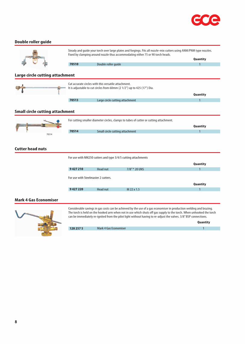
Double roller guide
Steady and guide your torch over large plates and forgings. Fits all nozzle-mix cutters using ANM/PNM type nozzles. Fixed by clamping around nozzle thus accommodating either 75 or 90 torch heads.
Quantity
9 427 210 Head nut 1
Cutter head nuts
For use with NM250 cutters and type 3/4/5 cutting attachments
Quantity
Large circle cutting attachment
Cut accurate circles with this versatile attachment. It is adjustable to cut circles from 60mm (2 1/2”) up to 425 (17”) Dia.
Quantity
70513 Large circle cutting attachment 1
70514 Small circle cutting attachment 1
Small circle cutting attachment
For cutting smaller diameter circles, clamps to tubes of cutter or cutting attachment.
Quantity
70514
8
9 427 220 Head nut 1
For use with Steelmaster 2 cutters.
Quantity
M 22 x 1.5
7/8” * 20 UNS
Mark 4 Gas Economiser
Considerable savings in gas costs can be achieved by the use of a gas economiser in production welding and brazing. The torch is held on the hooked arm when not in use which shuts off gas supply to the torch. When unhooked the torch can be immediately re-ignited from the pilot light without having to re-adjust the valves. 3/8” BSP connections.
Quantity
128 257 5 Mark 4 Gas Economiser 1

Shank with gas saver UNIVERSAL
Quantity
076 321 6 1
Combined shut-off valve and adjusting knob.Use: designed for use with soldering, brazing and heating torches UNIVERSAL
Technical Data
Hose connection: G 3/8” LH
Working pressure:
Adjustable pilot flame
Capacity: 12 kg/hLength: 195 mm
Weight: 0,36 kg
up to 4 bar
PB
Torch, tube connection Packaging
M14 x 1 blister
Gas:
Paint remover fan burner UNIVERSAL
Quantity
23705 1
Use: for removing old work and localised heating.
Technical Data
Working pressure:
Consumption PB:
Output: 2,83 kW
Length/width: 170/40 mm
Weight: 0,19 kg
1,5 - 2,0 bar
Connection
M14 x 1
220 g/h
UNIVERSAL air propane equipment
Ideal for plumbing, heating, and ventilation trades, the Butbro air propane shank has adjustable pilot flame and 3/8”BSP inlet. Spot/turbo(copper pipe)/specialburners connect directly to the shank for all plumbing applications. Heating heads are connected via stainless tubes for larger heating jobs such as roadworking/roofing/bitumen heating.
Soldering torch B-UNIVERSAL
Quantity
Use: for soldering and brazing; for point heating.
Connection Type
1 1
Technical Data
Working pressure:
Consumption PB:
Output:
Length:
Weight:
B-5 mm
0,69 - 0,85 kW/h
120 mm
0,09 kg
1,5 - 2,5 bar
54 - 66 g/h
Gas:
548 800 763 223 M14 x 1 B-5 mm
548 800 763 224 M14 x 1 B-7 mm
P, PB
B-7 mm
2,08 - 2,70 kW/h
138 mm
0,11 kg
1,5 - 2,5 bar
162 - 210 g/h
P, PB
9

Brazing torch TURBO-UNIVERSAL
Quantity
548 800 763 225 1
Use: for soldering and brazing, especially of copper piping systems
Connection Type
M14 x 1 T Ø12 4903 1 M14 x 1 T Ø14
4911 1 M14 x 1 T Ø17
Technical Data
Working pressure:
Consumption PB:
Output: 0,81 - 1,44 kW
Length: 155 mm
Weight: 0,13 kg
1,5 - 2,5 bar
63 - 112 g/h
T Ø12 T Ø17 T Ø20
3,50 - 4,94 kW
184 mm
0,17 kg
1,5 - 2,5 bar
272 - 384 g/h
5,66 - 7,08 kW
190 mm
0,19 kg
1,2 - 2,5 bar
440 - 550 g/h
548 800 763 228 1 M14 x 1 T Ø20
T Ø14
2,70 - 4,35 kW
178 mm
0,15 kg
1,5 - 2,5 bar
210 - 338 g/h
Gas: P, PB P, PB P, PBP, PB
Technical Data
Working pressure:
Consumption PB:
Output: 4,50 kW
Length: 190 mm
Weight: 0,20 kg
1,5 - 2,0 bar
350 g/h
GT ½” GT 1”
5,79 kW
190 mm
0,24 kg
1,5 - 2,0 bar
450 g/h
Gas: P, PBP, PB
Heating torch GT-UNIVERSAL
Use: for heating of pipes 1/2”or 1”; for pipe soldering and brazing jobs; preheating before tube bending.Use with neck tube.
Quantity Connection
548 914 094 500 1 M14 x 1
21089 1 M14 x 1GT ½”
GT 1”
GT ½”GT 1”
For copper pipe: 18 mm 22 mm 28 mm12 mm
Shrinkwrap torch S-UNIVERSAL
Use: available in two sizes for shrinkwrapping.
Quantity Connection
32003 1 M14 x 1
33670 1 M14 x 1S - 30 mmS - 40 mm
Technical Data
Working pressure:
Consumption PB:
1,5 bar
1 900 g/h
S - 30 mm S - 40 mm
1,5 bar
2 500 g/h
For Pipe max
12 mm 18 mm
22 mm28 mm
10

Heating torch H-UNIVERSAL
Use: for industrial heating; roofing and construction work.Use with neck tube.
Quantity
M20 x 1
Type Ø
548 800 763 217 1 548 800 763 218 1 4069 1 45 mm
548 800 763 219 1 548 800 763 220 1
50 mm60 mm
30 mm
40 mm
Technical Data
Working pressure:
Consumption PB:
Output: 8,55 - 13,59 kW
Length: 88 mm
Weight: 0,12 kg
1,0 - 4,0 bar
664 - 1056 g/h
H Ø40H Ø30
15,44 - 24,48 kW
95 mm
0,21 kg
1,0 - 4,0 bar
1200 - 1902 g/h
Gas: P, PBP, PB
Technical Data
Working pressure:
Consumption PB:
Output:
Length:
Weight:
H Ø60H Ø50
64,74 - 125,41 kW
125 mm
0,34 kg
1,0 - 4,0 bar
5030 - 9744 g/h
Gas: P, PB
H Ø45
48,68 - 97,69 kW
115 mm
0,30 kg
1,0 - 4,0 bar
3780 - 7590 g/h
P, PB
37,9 - 76,2 kW
100 mm
0,25 kg
1,0 - 4,0 bar
2500 - 5300 g/h
P, PB
Neck tube UNIVERSAL
Quantity
Manufactured in stainless steel.Use: designed to connect UNIVERSAL heating torches to shank UNIVERSAL. Head connection M 20x1 MALE. Torch connection M 14 x 1 FEMALE.
Connection Packaging Weight
2279 1 M14 x 1 plastic bag 0,11 kg
Type
130 mm
548 809 381 300 1 M14 x 1 plastic bag 0,14 kg
548 809 381 310 1 M14 x 1 plastic bag 0,19 kg 548 809 394 880 1 M14 x 1 plastic bag 0,25 kg
548 809 381 320 1 M14 x 1 plastic bag 0,29 kg 548 809 381 330 1 M14 x 1 plastic bag 0,35 kg 548 809 381 340 1 M14 x 1 plastic bag 0,44 kg
230 mm
350 mm
500 mm
600 mm
750 mm1000 mm
Support H-UNIVERSAL
Use: Allows hot heating torches to be rested safety on a horizontal surface. Assembled onto the neck tube of the torch.
Quantity
12476 1
Weight
0,15 kg
11

ANM short pattern
6 heating holes, 76 mm long.Use: Acetylene fuel gas.
Range Size
10132 3 - 6 mm size 1/32”
10364 5 - 12 mm size 3/64”
Cutting nozzles
76 mm
10116 10 - 75 mm size 1/16”
10564 70 - 100 mm size 5/64”
10332 90 - 150 mm size 3/32”
10764 140 - 200 mm size 7/64”
10018 190 - 300 mm size 1/8”
ANME long pattern
6 heating holes, 88 mm long.Use: Acetylene fuel gas.
Range Size
45132 3 - 6 mm size 1/32”
45364 5 - 12 mm size 3/64”
45116 10 - 75 mm size 1/16”
45564 70 - 100 mm size 5/64”
45332 90 - 150 mm size 3/32”
45764 140 - 200 mm size 7/64”
45018 190 - 300 mm size 1/8”
88 mm
PNM short pattern
9 spline inner, 76 mm long.Use: Propane fuel gas.
Range Size
18132 3 - 6 mm size 1/32”
18364 5 - 12 mm size 3/64”
18116 10 - 75 mm size 1/16”
18564 70 - 100 mm size 5/64”
18332 90 - 150 mm size 3/32”
18764 140 - 200 mm size 7/64”
18018 190 - 300 mm size 1/8”
PNME long pattern
9 spline inner, 88 mm long.Use: Propane fuel gas.
Range Size
46132 3 - 6 mm size 1/32”
46364 5 - 12 mm size 3/64”
46116 10 - 75 mm size 1/16”
46564 70 - 100 mm size 5/64”
46332 90 - 150 mm size 3/32”
46764 140 - 200 mm size 7/64”
46018 190 - 300 mm size 1/8”
76 mm
88 mm
12
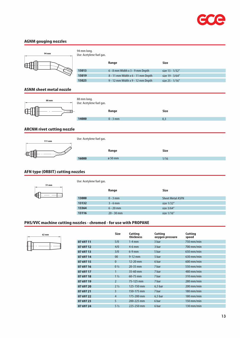
AGNM gouging nozzles
94 mm long.Use: Acetylene fuel gas.
Range Size
15013 6 - 8 mm Width x 3 - 9 mm Depth size 13 - 1/32”15019 8 - 11 mm Width x 6 - 11 mm Depth size 19 - 3/64”15025 9 - 12 mm Width x 9 - 12 mm Depth size 25 - 1/16”
94 mm
88 mm
ASNM sheet metal nozzle
88 mm long.Use: Acetylene fuel gas.
Range Size
14000 0 - 3 mm 0,3
ARCNM rivet cutting nozzle
Use: Acetylene fuel gas.
Range Size
16000 1/16
111 mm
51 mm
AFN type (ORBIT) cutting nozzles
Use: Acetylene fuel gas.
Range Size
13000 0 - 3 mm Sheet Metal ASFN13132 3 - 6 mm size 1/32”13364 6 - 20 mm size 3/64”13116 20 - 30 mm size 1/16”
ø 50 mm
13
PHS/VVC machine cutting nozzles - chromed - for use with PROPANE
Size
07 697 11 5/0
07 697 12 4/0
07 697 13 3/0
07 697 14 00
07 697 15 0
07 697 16 0 ½
07 697 17 107 697 18 1 ½
07 697 19 2
07 697 20 2 ½
07 697 21 3
07 697 22 407 697 23 5
07 697 24 5 ½
Cutting
1-4 mm
4-6 mm6-9 mm
9-12 mm12-20 mm20-35 mm
35-60 mm60-75 mm
75-125 mm
125-150 mm150-175 mm
175-200 mm200-225 mm
225-250 mm
Cutting
3 bar
3 bar5 bar
5 bar6 bar7 bar
7 bar7 bar
7 bar
6,5 bar7 bar
6,5 bar6 bar
6 bar
Cutting
750 mm/min
700 mm/min650 mm/min
630 mm/min600 mm/min550 mm/min
480 mm/min310 mm/min
280 mm/min
200 mm/min180 mm/min
180 mm/min150 mm/min
130 mm/min
thickness oxygen pressure speed62 mm

Lightweight swaged copper nozzles
For use on Orbit torch 1/4” x 26 TPI thread.
Range Size
62401 to 1 mm size 1
62402 1 - 1,5 mm size 2
Welding & heating nozzles
62403 1,5 - 2 mm size 3
62405 2 - 2,5 mm size 5
62407 2,5 - 3 mm size 7
62410 3 - 4 mm size 10
62413 4 - 5 mm size 1362418 5 - 6 mm size 18
62425 6 - 8 mm size 25
Type 2/3/4/5 swaged copper tube nozzles
For use on Type 2/3/4/5 Welding torch 7/16” x 27 TPI Thread (Sizes 1-90 Type 2 & 3), 31/64” x 27 TPI Thread (Sizes 45-90 using Heavy Duty Mixer)
Range Size
68501 to 1 mm size 1
68502 1 - 1,5 mm size 2
68503 1,5 - 2 mm size 3
68505 2 - 2,5 mm size 5
68507 2,5 - 3 mm size 7
68510 3 - 4 mm size 10
68513 4 - 5 mm size 1368518 5 - 6 mm size 18
68525 6 - 8 mm size 25
68535 8 - 10 mm size 35
68545 10 - 13 mm size 45
68555 13 - 19 mm size 5568570 19 - 25 mm size 70
68590 over 25 mm size 90
D.H. type solid copper tips
For use with Orbit torch, 5/16” x 25 TPI thread. Use in conjunction with DH neck 62017.
Range Size
62301 to 1 mm size 1
62302 1 - 1,5 mm size 2
62303 1,5 - 2 mm size 3
62305 2 - 2,5 mm size 5
62307 2,5 - 3 mm size 7
62310 3 - 4 mm size 10
62313 4 - 5 mm size 1362318 5 - 6 mm size 18
62325 6 - 8 mm size 25
14

Model ‘O’ brass welding tips
For use on Model ‘O’ Torch.
Size
47100 size 1
47200 size 2
47300 size 3
47400 size 4
47500 size 5
Superheating nozzles
For use on type 3/4/5 blowpipe in conjunction with heavy duty mixer 77555 and necks 78666 or 78777. Can also be used with NM250/Steelmaster in conjunction with superheating adaptor 0768929. Use: propane fuel gas.
Size
78991 1H
78992 2H
78993 3H
78994 4H
78995 5H
AHT heating nozzles
For use on type 3/4/5 equipment. In conjunction with necks 68777 or 68666. Use; Acetylene fuel gas.
Size
48425 AHT 25 heating tip
48450 AHT 50 heating tip
48410 AHT 100 heating tip
07 689 29 Superheating adaptor for NM Cutters
72000 - 163 000 Btu/H
102 000 - 188 000 Btu/H183 000 - 361 000 Btu/H236 000 - 406 000 Btu/H
250 000 - 618 000 Btu/H
38 mm
15

Single stage regulators
BUTBRO single stage regulators are precision built to latest BS EN ISO 2503 standards to provide maximum accuracy and safety. Features: Forged brass body and chromed bonnet. 63mm dual scale safety pressure gauges. Captive pressure adjusting screw. Models available: 2 gauge. Gaugeless. 1 gauge. Flo-Gauge. Mapp. Pre-set.Regulators are available for most common gases in either side or bottom entry with inlet threads suitable for any local cylinder connection standards. Regulators are also available with NEVOC type fittings.
Gas
07 835 12 Oxygen07 835 11 Oxygen
Regulators
07 835 13 Oxygen50554 Oxygen07 835 02 Acetylene07 835 01 Acetylene07 835 17 Propane07 835 07 Argon07 835 05 Argon
Inlet
300 bar
300 bar300 bar
300 bar25 bar25 bar
25 bar300 bar
300 bar
Outlet
10 bar
4 bar10 bar
40 bar1,5 bar1,5 bar
4 bar2 bar preset
4 bar
Inlet
G 5/8” (BS3)
G 5/8” (BS3)G 5/8” (BS3)
G 5/8” (BS3)G 5/8 LH (BS4) G 5/8 LH (BS4)
G 5/8 LH (BS4) G 5/8” (BS3)
G 5/8” (BS3)
Outlet
G 3/8”
G 3/8”G 3/8”
G 3/8”G 3/8 LHG 3/8 LH
G 3/8 LHG 3/8”
G 3/8”
07 835 06 Argon07 835 08 Argon50530 Mapp
300 bar300 bar
small cylinders
Flow 0-15 LPMFlow 0-50 LPM
small cylinders
G 5/8” (BS3)G 5/8” (BS3)
G 1/4 LH
G 3/8”G 3/8”
G 1/4 LH
Regulators - Bottom entry
07 835 14 Oxygen07 835 16 Oxygen
07 835 04 Acetylene07 835 03 Acetylene07 835 09 Argon07 835 10 CO *2
300 bar
300 bar
25 bar
25 bar300 bar200 bar
4 bar
10 bar
1,5 bar
1,5 bar4 bar4 bar
G 5/8” (BS3)
G 5/8” (BS3)
G 5/8 LH (BS4)
CGA 300G 5/8” (BS3)0,860 x 14TPI (BS8)
G 3/8”
G 3/8”
G 3/8 LH
9/16” x 18LHG 3/8”G 3/8”
Regulators - Side entry
Refrigeration regulators
This new range of regulators is specifically designed to meet the needs of the the heating, ventilation and air conditioning (HVAC)trades, for purge and leak test applications.Available in three pressure variants, the regulators are supplied with JIC fitting outlets.
Type
07 625 84 RS 40007 625 83 RS 60007 625 90 RS 750
Inlet pressure
300 bar
300 bar300 bar
Outlet pressure
28 bar
41 bar52 bar
Inlet connection
G 5/8”
G 5/8”G 5/8”
Outlet connection
W 11 x 1,25
W 11 x 1,25W 11 x 1,25
Balloon inflators
Available in three variants, with 230 bar inlet rating and BS3 connection.Use: Economy - Latex balloons (gaugeless, requires spanner to connect to cylinder) Standard - Latex balloons, (inc contents gauge and handweel) Combi - Latex and foil balloons
Type
07 628 17 Economy
07 628 16 Standard
07 628 18 Combi
07 835 11
07 835 17
07 835 10 with flowmeter
07 835 16
50530
07 628 16
07 628 18
07 835 15 Oxygen 300 bar 10 bar CGA 540 9/16” x 18LH
Gauges
0
22
202
01
222
0
2
2
2
212
2
pressure pressure connection connection
Gas Inlet Outlet Inlet Outlet Gauges pressure pressure connection connection
Flow
354 m /h321 m /h354 m /h
314 m /h314 m /h315 m /h315 m /h319 m /h
15 LPM50 LPM
354 m /h321 m /h
314 m /h314 m /h319 m /h320 m /h
354 m /h
Flow
* for CO regulators use heaters above 30 l/m.2
398 m /h
16

Mediline medical oxygen regulators and flowmeters - single stage therapy
Gas
07 816 60 Oxygen
07 816 61 Oxygen
07 816 65 Air
07 816 66 Air
CO gas heaters2
Fitted between the cylinder and the regulator, preventing freezing inside the regulator.
50831S CO2
50832S Argon
12450 CO2
Safety pressure gauges - BS EN 5171
Service
388 411 460 501 Acetylene
388 411 461 075 Acetylene
388 411 460 873 Oxygen
240 V240 V240 V
Outlet
G 3/8
BS quick connectorG 3/8
BS quick connector
Gas
MM327 7 Oxygen
MM327 9 Oxygen
MM327 8 Air
MM328 0 Air
Outlet
G 3/8 (0-15 LPM)
BS quick connector (0-15 LPM)G 3/8 (0-15 LPM)
BS quick connector (0-15 LPM)
Voltage
1/4” NPT
388 411 461 573 Oxygen
Pressure
2,5 bar
40 bar16 bar
400 bar
35 psi
550 psi230 psi
5600 psi
Ø
63 mm
63 mm63 mm
63 mm
Finish
Gold
GoldGold
Gold
388 413 350 502 Acetylene
388 811 360 500 Acetylene
388 413 351 075 Acetylene
1/4” BSPP
388 811 361 074 Acetylene
2,5 bar
2,5 bar40 bar
40 bar
35 psi
35 psi550 psi
550 psi
50 mm
63 mm50 mm
63 mm
Black
GoldBlack
Gold
388 413 350 512 General purpose
388 413 350 687 General purpose
388 413 350 873 General purpose
388 811 360 700 General purpose
2,5 bar
6 bar16 bar
16 bar
35 psi
90 psi230 psi
230 psi
50 mm
50 mm50 mm
63 mm
Black
BlackBlack
Gold
388 413 350 481 General purpose
388 413 350 162 General purpose
388 811 361 582 General purpose
388 413 351 402 General purpose
16 l/m
160 bar315 bar
400 bar
16 l/m
2300 psi4570 psi
5600 psi
50 mm
50 mm63 mm
50 mm
Black
BlackGold
Black
388 413 350 685 Oxygen
388 413 350 871 Oxygen
388 811 360 872 Oxygen
388 811 361 572 Oxygen
6 bar
16 bar16 bar
315 bar
90 psi
230 psi230 psi
4570 psi
50 mm
50 mm63 mm
63 mm
Black
BlackGold
Gold
388 413 351 400 Oxygen 400bar 5600 psi 63 mm Black
548 904 710 370 Crush washer for 1/4” BSPP gauge
Spare parts
Inlet
BS3
Bs3Bs3
Bs3
Regulators
Flowmeters
419 865 0 Chrome plated nut G3/8”
419 492 0 Chrome plated nipple G3/8” x 5 mm
Gas
BS8BS 3G 3/4
Thread
17

Multi-stage regulators for cylinder and manifold mounting
GCE multi-stage regulators are designed to provide accurate, fluctuation free delivery for precision applications such as machine cutting or laboratory use. The first stage reduces the inlet pressure by over 90% and the large second stage diaphragm ensures accurate delivery pressure. GCE multistage regulators are precision built to latest BS EN ISO 2503 and BS EN 7291 standards to provide maximum accuracy and safety.These regulators have the additional feature of being able to pipe away gases from the relief valve port, and comply with the stringent requirements of BS EN 7291.Features: Forged brass body. Safety Valve. 50mm dia dual scale safety pressure gauges. Captive pressure adjusting screw. Regulators are available for most common gases in either side or bottom entry with inlet threads suitable for any local cylinder connection standards. Regulators are also available with NEVOC type fittings.
07 621 44 Oxygen
07 621 45 Oxygen
Multi-stage regulators
07 621 43 Acetylene
07 621 81 Inert
07 621 46 Inert
07 621 47 Inert
07 621 48 Hydrogen
07 621 49 Hydrogen
07 621 52 Nitrous oxide
300 bar
300 bar25 bar
300 bar300 bar300 bar
300 bar300 bar
200 bar
4,0 bar
10,0 bar1,5 bar
2,0 bar4,0 bar10,0 bar
4,0 bar10,0 bar
10,0 bar
G 5/8”
G 5/8”G 5/8 LH
G 5/8”G 5/8”G 5/8”
G 5/8 LHG 5/8 LH
BS 13
G 3/8”
G 3/8”G 3/8 LH
G 3/8”G 3/8 “G 3/8”
G 3/8 LHG 3/8 LH
G 3/8”
Regulators - Bottom entry
07 621 98 Oxygen
07 621 99 Oxygen
07 621 96 Acetylene
07 621 82 Inert
07 621 97 CO *2
07 621 53
CO *2
300 bar
300 bar25 bar
300 bar200 bar200 bar
4,0 bar
10,0 bar1,5 bar
2,0 bar4,0 bar10,0 bar
G 5/8”
G 5/8”G 5/8 LH
G 5/8”0,860 x 14 TPI0,860 x 14 TPI
G 3/8”
G 3/8”G 3/8 LH
G 5/8”G 3/8”G 3/8”
Regulators - Side entry
07 621 50 Helium
07 621 51 Helium300 bar200 bar
4,0 bar10,0 bar
G 5/8”G 5/8”
G 3/8”G 3/8”
Gas Inlet Outlet Inlet Outlet Gauges pressure pressure connection connection
Flow
2
22
222
22
2
2
2
2
222
2
2
Gas Inlet Outlet Inlet Outlet Gauges pressure pressure connection connection
Flow
320 m /h348 m /h310 m /h
320 m /h348 m /h380 m /h
3191 m /h335 m /h
312 m /h
348 m /h310 m /h312 m /h316 m /h340 m /h
320 m /h
3191 m /h335 m /h
* for CO regulators use heaters 2
07 621 51
07 621 53
07 621 43
388 239 391 610
388 239 391 600
50081
0 - 15 LPM0 - 30 LPM
Flowmeters
Precision Flowmeter with brass finish, 3/8" BSP connections, available in 2 models, 15 LPM or 30 LPM.
Gauges
Flowmeter elbow 3/8” BSP
18
07 623 96
07 835 94
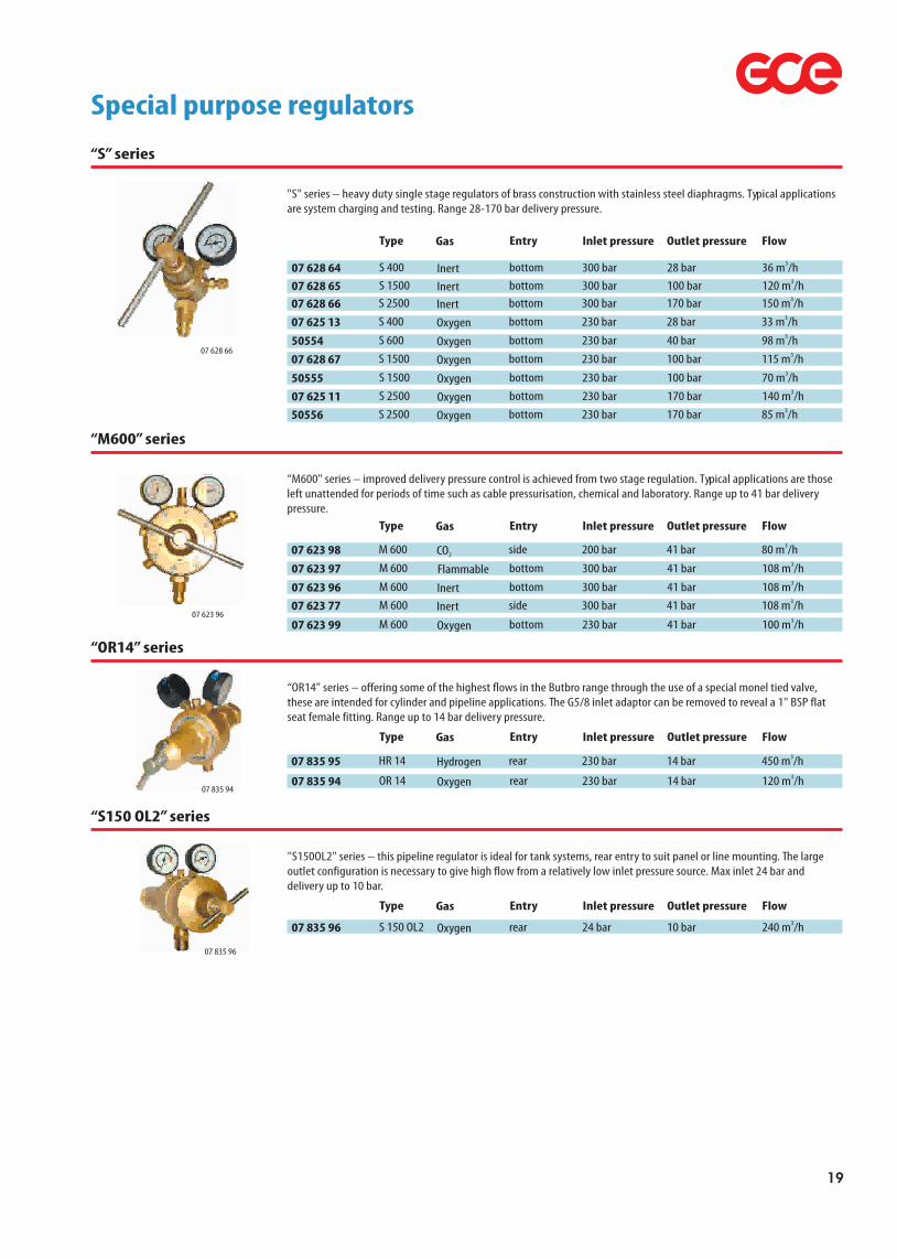
“S” series
"S" series – heavy duty single stage regulators of brass construction with stainless steel diaphragms. Typical applications are system charging and testing. Range 28-170 bar delivery pressure.
07 628 66
Gas
07 623 98 CO2
07 623 97 Flammable
07 835 95 Hydrogen
07 628 64 Inert
07 623 96 Inert07 623 77 Inert
07 628 65 Inert07 628 66 Inert
07 835 94 Oxygen
Inlet pressure
200 bar
300 bar
230 bar
300 bar
300 bar300 bar
300 bar300 bar
230 bar
Outlet pressure
41 bar
41 bar
14 bar
28 bar
41 bar41 bar
100 bar170 bar
14 bar
Type
M 600
M 600
HR 14
S 400
M 600M 600
S 1500S 2500
OR 14
Entry
side
bottom
rear
bottom
bottomside
bottombottom
rear
07 625 13 Oxygen
07 623 99 Oxygen
07 628 67 Oxygen50555 Oxygen07 625 11 Oxygen50556 Oxygen
230 bar
230 bar
230 bar
230 bar230 bar230 bar
28 bar
41 bar
100 bar
100 bar170 bar170 bar
S 400
M 600
S 1500
S 1500S 2500S 2500
bottom
bottom
bottom
bottombottombottom
07 835 96 Oxygen 24 bar 10 barS 150 OL2 rear
50554 Oxygen 230 bar 40 barS 600 bottom
Flow380 m /h
3108 m /h
3450 m /h
336 m /h
3108 m /h3108 m /h
3120 m /h3150 m /h
3120 m /h
333 m /h
3100 m /h
3115 m /h370 m /h
3140 m /h385 m /h
3240 m /h
398 m /h
Special purpose regulators
Gas Type Entry
“M600” series
“M600" series – improved delivery pressure control is achieved from two stage regulation. Typical applications are those left unattended for periods of time such as cable pressurisation, chemical and laboratory. Range up to 41 bar delivery pressure.
Gas Inlet pressure Outlet pressure Type Entry Flow
“OR14” series
“OR14" series – offering some of the highest flows in the Butbro range through the use of a special monel tied valve, these are intended for cylinder and pipeline applications. The G5/8 inlet adaptor can be removed to reveal a 1" BSP flat seat female fitting. Range up to 14 bar delivery pressure.
Gas Inlet pressure Outlet pressure Type Entry Flow
“S150 OL2” series
"S150OL2" series – this pipeline regulator is ideal for tank systems, rear entry to suit panel or line mounting. The large outlet configuration is necessary to give high flow from a relatively low inlet pressure source. Max inlet 24 bar and delivery up to 10 bar.
Inlet pressure Outlet pressure Flow
07 835 96
19

07 623 97 Flammable07 835 95 Hydrogen07 628 64 Inert07 623 96 Inert07 623 77 Inert07 628 65 Inert07 628 66 Inert07 835 94 Oxygen
300 bar230 bar
300 bar300 bar300 bar
300 bar300 bar
230 bar
41 bar14 bar
28 bar41 bar41 bar
100 bar170 bar
14 bar
M 600HR 14
S 400M 600M 600
S 1500S 2500
OR 14
bottomrear
bottombottomside
bottombottom
rear
07 625 13 Oxygen
07 623 99 Oxygen07 628 67 Oxygen50555 Oxygen07 625 11 Oxygen50556 Oxygen
230 bar
230 bar230 bar
230 bar230 bar230 bar
28 bar
41 bar100 bar
100 bar170 bar170 bar
S 400
M 600S 1500
S 1500S 2500S 2500
bottom
bottombottom
bottombottombottom
147 726 Oxygen 24 bar 10 barS 150 OL2 rear
50554 Oxygen 230 bar 40 barS 600 bottom
3450 m /h336 m /h
3108 m /h3108 m /h3120 m /h3150 m /h3120 m /h
333 m /h
3100 m /h3115 m /h
370 m /h3140 m /h
385 m /h3240 m /h
398 m /h
Gas
07 623 98 CO2
Inlet pressure
200 bar
Outlet pressure
41 bar
Type
M 600*
Entry
side
Regulator summary Flow
380 m /h3108 m /h
Outlet connections on "S" series regulators with delivery pressures above 28 bar are compression type, suitable for 1/4" OD tube pipework connection. S150OL2 pipeline regulator is fitted with 1" BSP RH female inlet and 3/4” BSP RH male outlet.
* for CO regulators use heaters 2
Special purpose regulator summary
20

Superguard FR50 reset flashback arrestor
A regulator mounted safety device suitable for all welding and cutting operations, fully complying with EN730, this "lift to reset" unit incorporates the following features:• FA Sintered flame arresting element• NV Non return valve to prevent reverse flow of gases• PV Pressure trip device, activated by pressure wave accompanying a flashback• TV Thermal trip device, activated by heat to permanently cut off the gas supply• SI Status indicator shows green when unit is ready for use. In the event of a flashback the item can be reset by lifting and releasing the bonnet.
Gas
50950 Oxygen50951 Fuel gas
Safety devices - flashback arrestors
50953 Oxygen50954 Fuel gas
Working pressure
0 - 10,0 bar
1,5 - 5,0 bar*0 - 10,0 bar
1,5 - 5,0 bar*
Inlet connection
G 3/8”
G 3/8 LHG 9/16” RH
G 9/16 LH
Outlet connection
G 3/8”
G 3/8 LHG 9/16” RH
G 9/16 LH
Slimguard 99 flashback arrestor
The new Slimguard 99 for regulator mounting has been redesigned incorporating an improved sintered filter and thermal trip device. Complies with EN730.• FA Sintered flame arresting element• NV Non return valve to prevent reverse flow of gases• TV Thermal trip device, activated by heat to permanently cut off the gas supply.
Gas
50920 Oxygen50921 Fuel gas50922 Oxygen50923 Fuel gas
Working pressure
0 - 10,0 bar
1,5 - 5,0 bar*0 - 10,0 bar
1,5 - 5,0 bar*
Inlet connection
G 3/8”
G 3/8 LHG 9/16” RH
G 9/16 LH
Outlet connection
G 3/8”
G 3/8 LHG 9/16” RH
G 9/16 LH
BUTBRO flashback arrestors are designed to protect the operator. Attention to the following points will greatly reduce the risk of backfire:Ensure all equipment is in good condition and regularly checked.Ensure all hose connectors are gas tight.Follow the manufactures instructions for the torch.Ensure pressure settings are correct.Purge hoses before lighting torch.Keep hands and tools clean. (Oil or grease can cause an explosion when in contact with oxygen). In the event of a backfire do not re-ignite the torch until the cause has been determined and remedied.
BUTBRO flashback arrestors require no routine maintenance other than regular checks for external leaks applicable to all gas equipment.BUTBRO flashback arrestors are sealed and tested during manufacture and no attempt should be made to dismantle or repair the unit. Should there be any doubt about the performance of the unit it should be replaced or returned to the manufacture for service.
SAFETY DEVICES
Some common causes of flashbacks are:
A flashback occurs when gases igniteinside the torch and will, if unchecked,travel back up the hose lines to theregulator and cylinders.
Faulty Equipment.Failure to purge hoses prior to lightingtorch.Incorrect lighting procedure.Blocked nozzle.Gas starvation.Incorrect pressure settings.Overheating.
FR63 high flow pipeline flashback arrestor
Designed for use with acetylene manifolds up to 1.5 bar, this line mounted arrestor is fitted with BSP11/2" inlet and outlet and 48mm pipe stubs.Flow Rate 50 M3/H maximum. The unit incorporates the following features:• FA SINTERED FLASH ARRESTOR element to quench a flashback.
Gas
07 624 52 Acetylene
* Acetylene 1-5 bar, Propane/Hydrogen/Methane/Natural gas 5,0 bar
* Acetylene 1-5 bar, Propane/Hydrogen/Methane/Natural gas 5,0 bar
21

Flameguard torch mounted flashback arrestors
A lightweight torch flashback arrestor specially designed for torch fitting. The unit incorporates the following features:• FA SINTERED FLASH ARRESTOR element to quench a flashback.• NV NON-RETURN VALVE to prevent reverse flow of gases.FILTER gauze to prevent foreign matter entering unit. Conforms to BS EN 730.
Connection torch
50965
50966
50961
50962
50975
50976
50971 50972
Gas
Oxygen
FuelOxygen
FuelOxygenFuel
OxygenFuel
Hose check valves torch mounted
Hose check valves prevent the reverse flow of gases beyond the torch inlets. BUTBRO hose check valves are manufactured to our own approved design and the unique method of assembly eliminates the use of soldered or bonded joints. They are suitable to use with Oxygen, Acetylene, Propane or Natural Gas and operate effectively on either nozzle mix or injector type torches or machine cutting torches.
Connection hose
6 mm tail
6 mm tail10 mm tail
10 mm tailG 3/8” male G 3/8” male LH
G 1/4” maleG 1/4” male LH
G 3/8”
G 3/8 LHG 3/8”
G 3/8 LHG 3/8”G 3/8 LH
G 1/4”G 1/4 LH
Suitable for hose
6 mm hose
6 mm hose10 mm hose
10 mm hoseAdd to existing 6/8/10 installationAdd to existing 6/8/10 installation
Add to existing 6 installationAdd to existing 6 installation
Connection torch
871 121
871 122
871 111
871 112
871 101
871 102
871 131 871 132
Gas
Oxygen
FuelOxygen
FuelOxygenFuel
OxygenFuel
G 3/8”
G 3/8 LHG 3/8”
G 3/8 LHG 3/8”G 3/8 LH
G 1/4”G 1/4 LH
Suitable for hose
6 mm hose
6 mm hose8 mm hose
8 mm hose10 mm hose10 mm hose
6 mm hose6 mm hose
22

Cutting Machine IMP-Speed - Acetylene, Propane, Natural Gas
This rugged, portable and economical machine is designed for accuracy and incorporates many great user benefits. A circlecutting attachment is part of the basic delivery package. The rugged body consists of two light alloy castings containingthe transformer, electric motor and gear box. For strip, chamfer and plate edge preparation, a second torch can be fitted.
Cutting Machines
Convenient Circle, Strip and Bevel High Speed CuttingCircle cuttingAn attachment is supplied with the machine enabling circles to be cut from 75 up to 1380 mm in single torch form,and up to 1740 mm when fitted with a second torch and a longer radius bar.
Strip CuttingTorch can be mounted on either side of the machine. Alternatively if narrower strips are required both torches maybe positioned on the same side with the counter balance weight fitted to maintain stabilityBevel Cutting. IMP can carry two torches for plate edge preparation.
Guided CuttingThe guide bars on the right hand side of the machine enable straight or predetermined curves to be cut with themachine directly on the plate surface.Straight cutting with track guidanceWhile straight cutting it is convenient to operate the machine with the specially designed 2 m long light alloy track. Sections can be added and secured by means of simple fully interlocking clip.
High Performance NEW higher speed version available up to 1700 mm/min Speed range permits low power plasma operation
Easy handlingLightweightWith its sturdy handle it is easy to carry (app. 9 kg) and to steer. It is well balanced due to its ingenious design and theuse of light alloy materials. The heaviest part of the machine is located above the wheel drive to ensure good traction.
Hand steeringThe castor wheel is released for hand guidance on slow curves and the machine is placed directly onto the plate.Easy to operateAll machine controls within a hand span. Unique clutch design for ease of operation. Changing nozzles is easy by moving the machine to its end.
••
14 088 700
14 088 704
14 088 705
14 088 709
222 101 4
14 088 708
14 088 703 14 088 701
IMP-Speed Acetylene
IMP-Speed Propane/Natural GasIMP-Speed basic
IMP-Speed PlasmaTorch nozzle mixPlasma torch clamp
Track 2 mExtension set for second torch without nozzles
Technical Data
Cutting speed:
Weight:
Move:
Cutting thickness:
Extension:forward and reverseup to 2 cutting torches
3 - 150 mm /0,12” - 6”100 - 1700 mm/min
9 kg / 20 lbs (complete with single torch and hoses)
Fuel gas: G 3/8 LH, hose diam. 8 mm; Oxygen: G 3/8”, hose diam. 8 mm
220 V / 110 V, 50 - 60 Hz60 W
Input hoses:
Power supply:
Power consumption:
Basic scale of deliveryIMP – Speed basic: Machine body, machine gas distribution manifold for one torch, torch holder, torch bar (length 342 mm), heat shield, radius pole, centerpiece of radius, connecting cable with shock-proof plug, nozzle nut spanner and instruction manual.IMP – Speed Acetylene / Propane: Equipment of basic version with nozzle mix torch, torch hoses and high speed cutting nozzle set 3-100 mm.IMP – Speed plasma: Equipment of basic version with prismatic clamp for plasma torch(ø25 – 40 mm).
23

Portable Pipe Cutting Machine PCM - Acetylene / Propane
Robust but lightweight portable pipe cutting machine PCM for Oxygen – Acetylene / Propane, Natural gas cutting ofsquare or bevel cuts. The machine body has a light-alloy cast base. The manual torch movement is realized by the chainwheel and chain with standard length 2,2m (approx. 7ft-8in) supplied with each machine. There are two types of themachine. The standard delivery consists flat wheels for easy movement on the tube surface. The Track band type uses flanged wheels to sit on and be guided by the round steel band mounted on the tube. The track band type for accurate edge preparation is modification of standard machine (field conversion) by special conversion kid supplied on customer request.
60201 Pipe cutting machine
Technical Data
Maximum pipe diameter
(on customer request):
Move:
Pipe diameter:
Pipe wall thickness:manual forward and reversesquare cutting up to 100 mm (4in), beveling 45° up to 50 mm (2in)
101 - 610 mm (4 - 24 in) standard machine
1220 mm (48 in)
9 kg (20 lbs) standard machine
0 - 45 deg.Oxygen G 3/8”, Fuel gas G 3/8 LH
Weight:
Bevel cut angle:
Input hoses connections:
MG 86 SA portable pantograph type cutting machine
This easy to use machine can reproduce profiles from a reusable steel template. The steel template is traced by a poweredmagnetic roller with a variable speed SCR control system to provide maximum stability. The template mounting arm isfully adjustable. Templates for internal and external tracing are easily produced by simply incorporating an allowance forthe tracing roller diameter and kerf. The torch uses standard PNME or ANME tips for use with Oxy-Propane or Oxy-Acetylene and torch holder for square andbevel cuts and can be swivelled up for easy tip maintenance and replacement. An automatic switch enables simultaneous use of the cutting Oxygen and the motor. The machine can be used for circlecutting up to 700 mm diameter and can cut up to 1700 mm diameter using the extended circle attachment. Weighing only 50 kg this machine is easily portable for use in any location.
60050 Cutting machine
Technical Data
Standard circle Ø:
Extended circle Ø:
Weight:
Motor:
Power:50 Kgs220 V AC
24 V DC30 - 700 mm
1700 mm
30 - 600 mm
Template magnet Ø:
3 - 100 mm100 - 1000 mm/min
+/- 0,5 mm10 mm
Square edges length:
Cutting thickness:
Cutting speed:Cutting accuracy:
24

Welding hoses and clips
Single hose unfitted
A hose which is highly resistant to kinks and abrasion. Conforms to BS EN 559.Working pressure 290 P.S.I., safety factor in excess of 4 to 1.Colour: Blue - Oxygen. Red - Acetylene. Orange - Propane.Supplied in coils of 50 meters.
Length
Single hose-Oxygen
272 321 106 050 Hose-grooved 50 m 272 321 311 304 Hose-grooved 50 m 3,5 x 8 (15) mm
3,5 x 6,3 (13,3) mm
272 321 311 306 Hose-grooved 50 m 3,5 x 10 (17) mm
Wall thickness I.D (O.D.)
Single hose-Acetylene
272 321 006 041 Hose-grooved 50 m
272 321 118 050 Hose-grooved 50 m3,5 x 8 (15) mm
3,5 x 6,3 (13,3) mm
272 321 311 206 Hose-grooved 50 m 3,5 x 10 (17) mm
272 321 063 035 Hose-smooth 50 m 272 321 009 136 Hose-smooth 50 m
Single hose-Propane/Butane
3 x 6,3 (12,3) mm
3,5 x 8 (15) mm272 321 311 006 Hose-smooth 50 m 3,5 x 10 (17) mm
Twin hose unfitted
LengthTwin hose-Oxygen/Acetylene
272 333 066 020 Twin hose OX/AC 25 m 272 333 066 617 Twin hose OX/AC 40 m 3,5 x 6,3 x 6,3 (13,3 + 13,3) mm
3,5 x 6,3 x 6,3 (13,3 + 13,3) mm
272 333 066 100 Twin hose OX/AC 100 m 3,5 x 6,3 x 6,3 (13,3 + 13,3) mm Twin hose OX/AC 100 m
272 333 110 080 Twin hose OX/AC 20 m 3,0 x 10 x 10 (16 + 16) mm3,5 x 8 x 8 (15 + 15) mm
272 333 110 081 Twin hose OX/AC 40 m 3,0 x 10 x 10 (16 + 16) mm
272 333 088 100
Wall thickness I.D (O.D.)
25
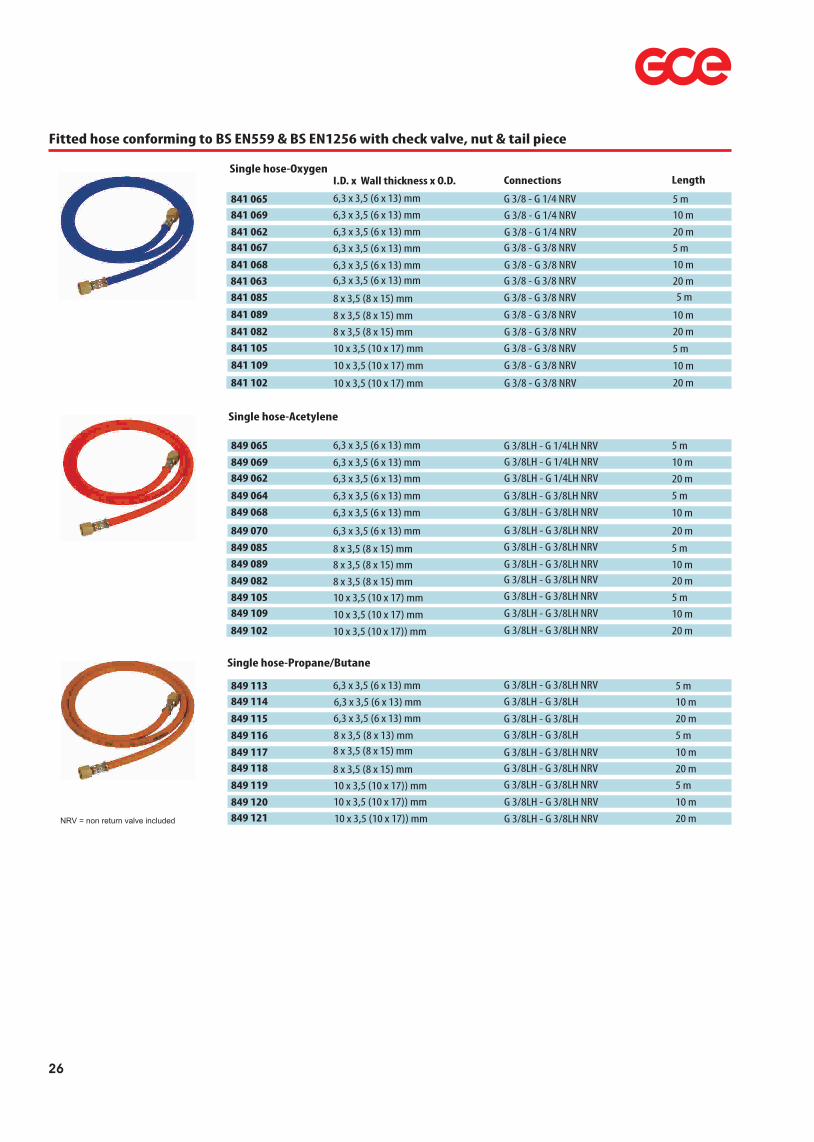
Fitted hose conforming to BS EN559 & BS EN1256 with check valve, nut & tail piece
841 063 G 3/8 - G 3/8 NRV 20 m
841 065 G 3/8 - G 1/4 NRV 5 m
841 067 G 3/8 - G 3/8 NRV 5 m
LengthSingle hose-Oxygen
841 068 G 3/8 - G 3/8 NRV 10 m
841 069 G 3/8 - G 1/4 NRV 10 m
841 089 G 3/8 - G 3/8 NRV 10 m
6,3 x 3,5 (6 x 13) mm
8 x 3,5 (8 x 15) mm
6,3 x 3,5 (6 x 13) mm
6,3 x 3,5 (6 x 13) mm
6,3 x 3,5 (6 x 13) mm
841 085 G 3/8 - G 3/8 NRV 5 m
841 082 G 3/8 - G 3/8 NRV 20 m
841 102 G 3/8 - G 3/8 NRV 20 m
841 105 G 3/8 - G 3/8 NRV 5 m 10 x 3,5 (10 x 17) mm
10 x 3,5 (10 x 17) mm
8 x 3,5 (8 x 15) mm
8 x 3,5 (8 x 15) mm
I.D. x Wall thickness x O.D.
6,3 x 3,5 (6 x 13) mm
841 109 G 3/8 - G 3/8 NRV 10 m10 x 3,5 (10 x 17) mm
Connections
849 113 5 m
849 117 10 m 849 118 20 m
Single hose-Propane/Butane
849 119 5 m
849 120 10 m 849 121 20 m
8 x 3,5 (8 x 15) mm
10 x 3,5 (10 x 17)) mm10 x 3,5 (10 x 17)) mm
8 x 3,5 (8 x 15) mm10 x 3,5 (10 x 17)) mm
849 114 10 m
849 115 20 m
849 116 5 m 8 x 3,5 (8 x 13) mm
6,3 x 3,5 (6 x 13) mm6,3 x 3,5 (6 x 13) mm
6,3 x 3,5 (6 x 13) mm G 3/8LH - G 3/8LH NRV
G 3/8LH - G 3/8LH NRVG 3/8LH - G 3/8LH NRVG 3/8LH - G 3/8LH NRV
G 3/8LH - G 3/8LH NRV
G 3/8LH - G 3/8LH NRV
G 3/8LH - G 3/8LH
G 3/8LH - G 3/8LH G 3/8LH - G 3/8LH
NRV = non return valve included
841 062 G 3/8 - G 1/4 NRV 20 m6,3 x 3,5 (6 x 13) mm
849 064 5 m
849 065 5 m
849 062 20 m
Single hose-Acetylene
849 070 20 m
849 082 20 m
849 085 5 m
6,3 x 3,5 (6 x 13) mm
8 x 3,5 (8 x 15) mm
8 x 3,5 (8 x 15) mm
6,3 x 3,5 (6 x 13) mm
6,3 x 3,5 (6 x 13) mm
849 089 10 m
849 102 20 m
849 105 5 m 849 109 10 m 10 x 3,5 (10 x 17) mm
10 x 3,5 (10 x 17) mm
8 x 3,5 (8 x 15) mm
10 x 3,5 (10 x 17)) mm
6,3 x 3,5 (6 x 13) mm
G 3/8LH - G 1/4LH NRV
G 3/8LH - G 1/4LH NRV
G 3/8LH - G 3/8LH NRV
G 3/8LH - G 3/8LH NRV
G 3/8LH - G 3/8LH NRV
G 3/8LH - G 3/8LH NRV
G 3/8LH - G 3/8LH NRV
G 3/8LH - G 3/8LH NRV
G 3/8LH - G 3/8LH NRV
G 3/8LH - G 3/8LH NRV849 068 10 m
849 069 10 m
6,3 x 3,5 (6 x 13) mm
6,3 x 3,5 (6 x 13) mm
G 3/8LH - G 3/8LH NRV
G 3/8LH - G 1/4LH NRV
26

Twin hose fitted
841 060
841 080
Length
841 081
841 083
849 060 6,3 x 3,5-6,3 x 3,5 (6 x 13) mm
8 x 3,5-8 x 3,5 (8 x 15) mm
8 x 3,5-8 x 3,5 (8 x 15) mm8 x 3,5-8 x 3,5 (8 x 15) mm
849 061
849 066
849 110 849 111 10 x 3,5-10 x 3,5 (10 x 17) mm
10 x 3,5-10 x 3,5 (10 x 17) mm
6,3 x 3,5-6,3 x 3,5 (6 x 13) mm
6,3 x 3,5-6,3 x 3,5 (6 x 13) mm
6,3 x 3,5-6,3 x 3,5 (6 x 13) mm
849 112
849 063 6,3 x 3,5-6,3 x 3,5 (6 x 13) mm
6,3 x 3,5-6,3 x 3,5 (6 x 13) mm
10 x 3,5-10 x 3,5 (10 x 17) mm
849 071
ConnectionsI.D. x Wall thickness x O.D.
G 3/8 LH - RH G 3/8 - RH NRV
G 3/8 LH - RH G 3/8 - RH NRVG 3/8 LH - RH G 3/8 - RH NRVG 3/8 LH - RH G 3/8 - RH NRV
G 3/8LH - RH G 1/4LH - RH NRV
G 3/8 LH - RH G 3/8 - RH NRV
G 3/8LH - RH G 1/4LH - RH NRV
G 3/8 LH - RH G 3/8 - RH NRVG 3/8 LH - RH G 3/8 - RH NRV
G 3/8 LH - RH G 3/8 - RH NRV
G 3/8LH - RH G 1/4LH - RH NRV
G 3/8 LH - RH G 3/8 - RH NRV
5 m
5 m
10 m
20 m
5 m
10 m
10 m
5 m
20 m
20 m
20 m
10 m
NRV = non return valve included
WP24020 MUJ-FIT 13(one ear) 20 WP24022 MUJ-FIT 15(one ear) 20
WP90330 Oetiker(two ear) 13-15 20
Quantity
WP90340 Oetiker(two ear) 15-18 20
WP90346 Jubilee (screwdriver)8-12 20 WP90348 Jubilee (screwdriver)10-16 20
8 x 15; 8 x 16 mm
Hoses
8 x 15; 8 x 16 mm
5 x 12 - 6 x 13; 6 x 14 mm
6 x 13; 6 x 14 mm8 x 15; 8 x 16 mm
WP90352 Jubilee (screwdriver)12-22 20
WP24024 O clip pincers 1
-
-
Hose clips
6 x 13; 6 x 14 mm
EASY FIX
85034 Oetiker(two ear) 17-20 20 10 x 17 mm
Safety Curtains / Welding Screens
A portable free standing screen enabling the welding area to be enclosed thus protecting the surrounding workspace from the effects of glare and spatter. Constructed from green translucent PVC. This material complies with EN 1598 and is both UV stabilised and self extinguishing. Overall size - 6’ x 6’ (Curtain: 5’9" x 5’3").
554 40TC 6’ x 6’
SizeSize
Portable welding screen Green
Colour
27
28
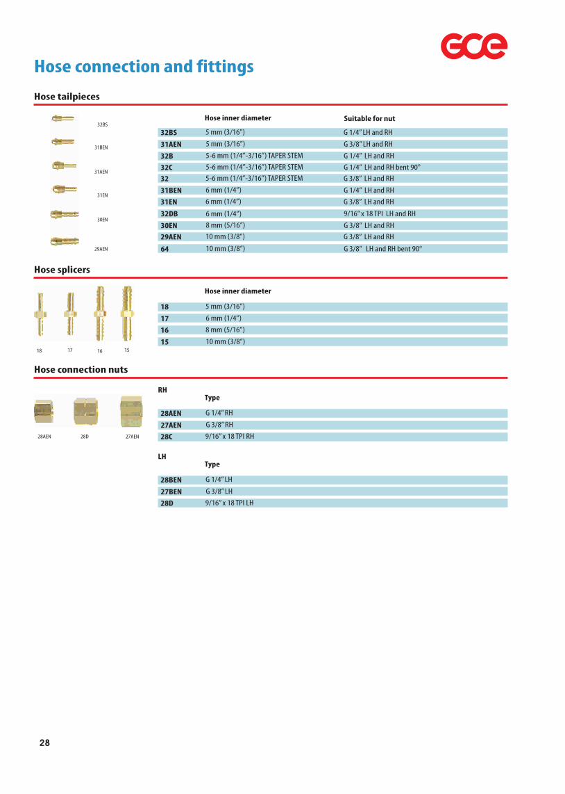
Hose tailpieces
Hose connection and fittings
Hose inner diameter
29AEN 10 mm (3/8”)30EN 8 mm (5/16”)
31EN 6 mm (1/4”)
31AEN 5 mm (3/16”)
31BEN 6 mm (1/4”)32 5-6 mm (1/4”-3/16”) TAPER STEM
32B 5-6 mm (1/4”-3/16”) TAPER STEM
32BS 5 mm (3/16”)
32C
Suitable for nut
G 3/8” LH and RH G 3/8” LH and RH
G 3/8” LH and RH
G 3/8” LH and RH
G 1/4” LH and RH
G 3/8” LH and RH
G 1/4” LH and RH
G 1/4” LH and RH
G 1/4” LH and RH bent 90°
32DB 6 mm (1/4”) 9/16” x 18 TPI LH and RH
5-6 mm (1/4”-3/16”) TAPER STEM
64 10 mm (3/8”) G 3/8” LH and RH bent 90°
Hose splicers
Hose inner diameter
18 5 mm (3/16”)
17 6 mm (1/4”)
16 8 mm (5/16”)
15 10 mm (3/8”)
Hose connection nuts
Type
28AEN G 1/4” RH
27AEN G 3/8” RH
28C 9/16” x 18 TPI RH
RH
Type
28BEN G 1/4” LH
27BEN G 3/8” LH
28D 9/16” x 18 TPI LH
LH
29AEN
30EN
31EN
31AEN
31BEN
32BS
18 17 16 15
28AEN 27AEN28D
29
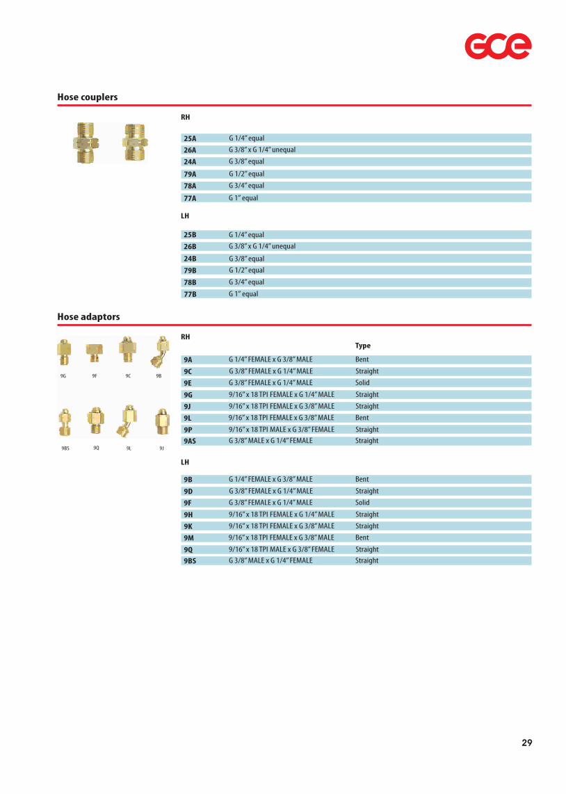
Hose couplers
RH
24A G 3/8” equal
25A G 1/4” equal
26A G 3/8” x G 1/4” unequal
77A G 1” equal
78A G 3/4” equal 79A G 1/2” equal
24B G 3/8” equal
25B G 1/4” equal
26B G 3/8” x G 1/4” unequal
77B G 1” equal 78B G 3/4” equal 79B G 1/2” equal
LH
Hose adaptors
RH
9A G 1/4” FEMALE x G 3/8” MALE
9C G 3/8” FEMALE x G 1/4” MALE
9E G 3/8” FEMALE x G 1/4” MALE
9G 9/16” x 18 TPI FEMALE x G 1/4” MALE
9J 9/16” x 18 TPI FEMALE x G 3/8” MALE
9L 9/16” x 18 TPI FEMALE x G 3/8” MALE
9P 9/16” x 18 TPI MALE x G 3/8” FEMALE9AS G 3/8” MALE x G 1/4” FEMALE
LH
Bent
StraightSolid
Straight
StraightBent
StraightStraight
Type
9B G 1/4” FEMALE x G 3/8” MALE
9D G 3/8” FEMALE x G 1/4” MALE
9F G 3/8” FEMALE x G 1/4” MALE
9H 9/16” x 18 TPI FEMALE x G 1/4” MALE
9K 9/16” x 18 TPI FEMALE x G 3/8” MALE
9M 9/16” x 18 TPI FEMALE x G 3/8” MALE
9Q 9/16” x 18 TPI MALE x G 3/8” FEMALE9BS G 3/8” MALE x G 1/4” FEMALE
Bent
StraightSolid
Straight
StraightBent
StraightStraight
9G 9F 9C 9B
9BS 9Q 9L 9J

Line regulators LINEMASTER
Maximum inlet pressure 30 bar. Inlet ¼” NPT male, outlet G3/8 RH or LH male cone. For a new installation both aLinemaster regulator and Linemaster Outlet Point are required.
Outlet points
07 817 08 1,5 bar07 817 07 2,0 bar07 817 04 4,0 bar
07 816 97 12,5 bar07 817 06 2,0 bar
07 816 99 12,5 bar
Outlet pressure
07 817 03 4,0 bar
Gas
AcetyleneFlammable (LH)
Flammable (LH)
Flammable (LH)
Inert
InertInert
Main benefits: simple installation and lower cost, individual work station control, non-return valves fitted to prevent back flow and pipeline contamination, quickvisual indication of status with quarter turn isolation valves, complies with all current EN and British Standards, meets BCGA Codes of Practice.
Linemaster Outlet Points
Maximum inlet pressure 30 bar except outlets fitted with flashback arresters, which are inert 10 bar, flammable 5 barand Acetylene 1.5 bar. Inlet connections: inert & flammable 15 mm solder socket, Acetylene G½½ female. Outlet points arefitted with a non-return valve, isolation valve, regulator block, wall mounting bracket. The Acetylene outlet always has aflashback arrestor but on outlets for Oxygen and flammable gases it is optional.
MM0268 with flasback arrestor FR 34MM0269 MM1748
TypeGas
AcetyleneInert
Oxygen
Series 300 Outlet Point Assemblies
Maximum inlet pressure 25 bar. Inlet connections. inert & flammable 15 mm solder socket, Acetylene G½½ female.Outlet is G3/8 RH or LH male cone to suit standard welding hose, this can be removed leaving ¼ NPT female for usewith compression fittings or similar. All outlets points are fitted with a non-return valve, isolation valve, regulator, outletpressure gauge, dirt inlet filter, wall mounting bracket. The Acetylene outlet always has a flashback arrestor. If a flashbackarrestor is required for Oxygen and flammable gases, it can be fitted to the outlet of the assembly. Flammable gases:Hydrogen + mixtures, Methane + mixtures, Propane. Please state gas and service pressure when ordering.
MM2010-22 1,5 bar07 817 76 2,0 bar07 817 77 5,0 bar
07 817 78 10,0 bar07 817 79 2,0 bar
Outlet pressure
07 817 81 10,0 bar
Gas
AcetyleneInert (RH)
Inert (RH)
Inert (RH)
Flammable (LH)Flammable (LH)
30
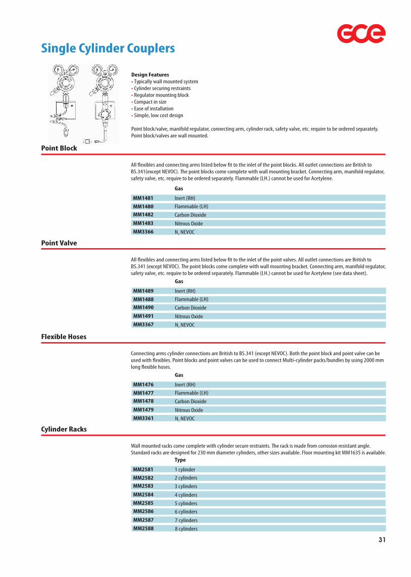
Single Cylinder Couplers
Design Features Typically wall mounted system Cylinder securing restraints Regulator mounting block Compact in size Ease of installation Simple, low cost design
Point block/valve, manifold regulator, connecting arm, cylinder rack, safety valve, etc. require to be ordered separately.Point block/valves are wall mounted.
••••••
Point Block
All flexibles and connecting arms listed below fit to the inlet of the point blocks. All outlet connections are British toBS.341(except NEVOC). The point blocks come complete with wall mounting bracket. Connecting arm, manifold regulator,safety valve, etc. require to be ordered separately. Flammable (LH.) cannot be used for Acetylene.
MM1481 Inert (RH)MM1480 Flammable (LH)MM1482 Carbon Dioxide
MM1483 Nitrous OxideMM3366 N NEVOC2
Gas
Point Valve
All flexibles and connecting arms listed below fit to the inlet of the point valves. All outlet connections are British toBS.341 (except NEVOC). The point blocks come complete with wall mounting bracket. Connecting arm, manifold regulator,safety valve, etc. require to be ordered separately. Flammable (LH.) cannot be used for Acetylene (see data sheet).
MM1489 Inert (RH)MM1488 Flammable (LH)MM1490 Carbon Dioxide
MM1491 Nitrous OxideMM3367 N NEVOC2
Gas
Flexible Hoses
Connecting arms cylinder connections are British to BS.341 (except NEVOC). Both the point block and point valve can beused with flexibles. Point blocks and point valves can be used to connect Multi-cylinder packs/bundles by using 2000 mmlong flexible hoses.
MM1476 Inert (RH)MM1477 Flammable (LH)MM1478 Carbon Dioxide
MM1479 Nitrous OxideMM3361 N NEVOC2
Gas
Cylinder Racks
Wall mounted racks come complete with cylinder secure restraints. The rack is made from corrosion resistant angle.Standard racks are designed for 230 mm diameter cylinders, other sizes available. Floor mounting kit MM1635 is available.
MM2581 1 cylinderMM2582 2 cylindersMM2583 3 cylinders
MM2584 4 cylindersMM2585 5 cylinders
Type
MM2586 6 cylinders
MM2587 7 cylindersMM2588 8 cylinders
31

Manifolds - complete packages
Manifolds are available in manual or automatic changeover versions. Packages are supplied complete with frames, header pipework, pigtails, non return valves, HP isolating valves, 10 bar regulator, 11.2 bar relief valve and line isolation kit. Acetylene versions are also available on request.Please refer to latest edition of “Central Gas Supply” catalogue, available on request.
Manifold Equipment
Manifolds - couplers, adaptors and fitting
Type
63A Adaptor - 90° cylinder adaptor
63C Adaptor - straight cylinder adaptor
61A Adaptor - 3 branch adaptor
59A Adaptor - 2 branch adaptor
50860 Adaptor - G 1/4” MALE x G 3/8 loose nut
50353A Adaptor - soldering 3/8 loose nut for 15 mm
60A Blanking plug 25C Coupler - 1/4NPT Equal coupler RH
MMO547
Inlet connection
G 5/8”M
G 5/8”M G 5/8”M
G 5/8”M G 1/4” M RH3/8”
G 5/8”M 1/4” NPT M
G 3/8” M
Outlet connection
G 5/8”F
G 5/8”F G 5/8”F
G 5/8”F G 3/8”F 15 mm tube
-1/4” NPT M
G 3/8” M
Rating
230 bar
230 bar230 bar
230 bar30 bar30 bar
230 bar30 bar
30 barMM1400 Line valve 1/4 turn butterfly operated
50320 Line valve 1/4 turn lever operated07 652 78 Shut off valve - handwheel
1/4” NPT F
G 3/8” M W 21,8 x 1/14 RH
1/4 NPT F
G 3/8” M W 21,8 x 1/14 LH
30 bar
30 bar300 bar
Line valve 1/4 turn butterfly operated
RH
Type
63B Adaptor - 90° cylinder adaptor
63D Adaptor - straight cylinder adaptor
61B Adaptor - 3 branch adaptor
59B Adaptor - 2 branch adaptor
50861 Adaptor - G 1/4” MALE x G 3/8 LH loose nut
50353B Adaptor - soldering 3/8 loose nut for 15 mm
60B Blanking plug MMO546 Line valve 1/4 turn butterfly operated
50321
Inlet connectionG 5/8”M LH
G 5/8”M LHG 5/8”M LH
G 5/8”M LHG 1/4” M RH
3/8” LH
G 5/8”M LHG 3/8” M LH
G 3/8” M LH
Outlet connectionG 5/8”F LH
G 5/8”F LHG 5/8”F LH
G 5/8”F LHG 3/8”F LH
15 mm tube
-G 3/8” M LH
G 3/8” M LH
Rating
230 bar
230 bar230 bar
230 bar30 bar
30 bar
230 bar30 bar
30 barLine valve 1/4 turn lever operated
LH
34A Adaptor 1/4NPTM x G3/8M 1/4NPTM G3/8M30 bar
34B Adaptor 1/4NPTM x G3/8M LH 1/4NPT M G3/8 M LH30 bar
Pipeline adaptors
50860 1/4” NPT x 3/8” H/D loose nut RH34A 1/4” NPT x 3/8” RH50861 1/4” NPT x 3/8 H/D loose nut LH
34B 1/4” NPT x 3/8 LH
59B
63D
63A
61A
32

Flexible hoses
Can be used with most cylinder orientation. Fitted with full length restraining/anti-whip wire. Inlet filters fitted to all cylinder connection flexibles. Gas quality linings. End fittings high strength brass. Cleaned to Oxygen Cleanliness Standards. Acetylene flexible fitted with non-return valve.
MM2526
MM2527
MM2528
MM2529
MM2530
MM2546
MM2531
MM2532
Length
600 mm
1000 mm
1500 mm
2000 mm3000 mm5000 mm
MM2533
MM2534
MM2535
MM2590
High pressure flexible (G3/8 loose nut & nipple - 1/4NPT.female)
High pressure flexible (G5/8RH.bullnose - G3/8 loose nut & nipple)
600 mm
1000 mm
1500 mm
2000 mm3000 mm5000 mm
MM2536
MM2537
MM2538
MM2539
MM2540
MM2591
High pressure flexible (G5/8LH.bullnose - G3/8 loose nut & nipple)
600 mm
1000 mm
1500 mm
2000 mm3000 mm5000 mm
MM2541
MM2542
MM2543
MM2544
MM2545
MM2592
High pressure flexible (G3/8 loose nut & nipple both ends)
600 mm
1000 mm
1500 mm
2000 mm3000 mm5000 mm
MM2598
MM2599
High pressure Oxygen flexible (G5/8RH.bullnose - G3/8 loose nut & nipple)
1000 mm
2000 mm
MM3361
MM3362
High pressure flexible (NEVOC inert - G3/8 loose nut & nipple)
600 mm
2000 mm
MM3363
MM3364
MM3365
High pressure flexible (Carbon Dioxide - G3/8 loose nut & nipple)
600 mm
1000 mm
2000 mm
MM3513
MM3436
MM3514
High pressure flexible Acetylene (G5/8 LH - G3/8 loose nut & nipple)
600 mm
1000 mm
2000 mm
33

Low pressure fine adjustment valves and adaptors(10 bar)
Fine adjustment valves
Gas
37A Oxygen
37B Acetylene
38C Oxygen38D Acetylene
Inlet connection
G 3/8” RH MALE
G 3/8” LH MALE
1/4” NPT MALE1/4” NPT MALE
Outlet connection
G 3/8” RH MALE
G 3/8” LH MALE
G 3/8” RH MALEG 3/8” LH MALE
Fine adjustment valves with swivel nut
Gas
39C Oxygen
39D Acetylene
Swivel nut
G 3/8” RH
G 3/8” LH
Outlet connection
G 3/8” RH MALE
G 3/8” LH MALE
Twin outlet valves with swivel nut (”Y” valves)
Gas
47A Oxygen
47B Acetylene
Swivel nut
G 3/8” RH
G 3/8” LH
Outlet connection
G 3/8” RH MALE
G 3/8” LH MALE
These allow two blowpipes to be used from one regulator outlet.
‘Y’ pieces, ‘T’ pieces for branching two hose from one
LH
RH
‘Y’ piece with swivel nut G 3/8” fitted with nuts and 10 mm nipples
65A
66A
‘T’ piece with G 3/8” RH/LH nuts and 10 mm nipples
65B ‘Y’ piece with swivel nut G 3/8” LH fitted with nuts and 10 mm nipples
66B ‘T’ piece with G 3/8” LH nuts and 10 mm nipples
65A
66A
34

Cylinder valves
Cylinder valves
Type
07 652 56 Industrial
07 655 73 Industrial
07 657 26 Industrial
07 655 72 Industrial*
07 657 25 Industrial*
07 751 12 Industrial
07 750 49 Industrial07 759 56 Industrial
07 653 89
07 755 35 Pin index
07 654 14 Pin index07 653 40 Pin index
Pin index
07 653 97 Pin index
07 653 39 Pin index
07 754 67 Pin index
938 367 0
Fill adaptor
939 066 1
Fill adaptor
K000 000 028 Burst disc*
Industrial valves are manufactured to EN 849. Medical pin index valves are manfactured to EN 850 and are CE marked.All industrial valves are handwheel operated, supplied in boxes of 20.
Gas
Acetylene
Ar/N -CO2 2
Ar/N -CO2 2
CO2
CO2
H /Mixes2
HeliumOxygen
Air
EntonoxOxygen
Air
Oxygen
OxygenOxygen
CO2
Ar/N -CO2 2
CO2
Service
25 bar
230 bar230 bar
190 bar190 bar300 bar
230 bar230 bar
200 bar
200 bar200 bar
200 bar
200 bar
200 bar200 bar
190 bar230 bar190 bar
Inlet
25E
25E25E
25E25E25E
25E25E
M 18
18T (0,715)17E
25E
18T (0,715)
25EM 18
G 1/4 MBS3 - G 5/8F
Outlet
BS4 - G 5/8 LH
BS3 - G 5/8BS3 - G 5/8
BS8 - W 21,8BS8 - W 21,8BS4 - G 5/8 LH
BS3 - G 5/8BS3 - G 5/8
Air pin
Entonox pinOxy pin
Air pin
Oxy pin
Oxy pinOxy pin
BS8 - W 21,8BS3 - G 5/8 M
* Burst Disc - 190 bar
Finish
Brass
BrassBrass
BrassBrassBrass
BrassBrass
Chromed
ChromedChromed
Chromed
Chromed
ChromedChromed
BrassBrassMonel
Residual pressure
Redidual pressure
Redidual pressure
use with 0765572use with 07655730765572/0765725
938 367 0
939 066 1 07 759 56 07 653 97
07 655 72
07 655 73
35
86001
548 901 256 793
Large twin oxy acetylene cylinder trolley (accepts cylinder diameter 240mm x 310mm max)
Small caddypak cylinder trolley (accepts cylinder diameter 175mm x 175mm max)
Cylinder trolleys
Perfectly balanced trolleys of welded steel construction with solid tyres and safety retaining chains/bars.Two models available for large and small cylinders.

Welding, cutting & heating dataWelding - ORBIT & MK 3/A torches
Nozzle
mm in size bar PSI bar PSI l/h ft3/h l/h ft3/h l/h ft3/h mm/m in/m
3 1/8 S/M 2,1 30 0,3 4 650 30 120 4,5 220 8 110 4
6 1/4 1/32 2,1 30 0,15 2 710 25 255 9 255 8 255 8
20 3/4 3/64 2,1 30 0,15 2 1415 50 255 9 225 8 225 8
25 1 1/16 3,8 55 0,15 2 3400 120 255 9 225 8 225 8
50 2 1/16 5,3 75 0,20 3 4530 60 310 11 285 10 285 10
Material Tk'ness Heating oxygenApprox Cutting
Speeds
Operating pressure Gas consumption
Oxygen Acetylene Cutting Oxygen Acetylen
Cutting - ACETYLENE - ORBIT torch
Cutting - ACETYLENE - MK 3/A & 18/90 cutters (ANM Nozzles)
Nozzle
mm in size bar PSI bar PSI l/h ft3/h l/h ft3/h l/h ft3/h mm/m in/m
Sheet ASNM 1,5 20 0,14 2 800 28 85 3 85 3 - -
6 1/4 1/32 1,8 25 0,14 2 800 28 480 15 400 14 510 20
13 1/2 3/64 2,1 30 0,21 3 1900 67 570 20 510 18 480 19
25 1 1/16 2,8 40 0,14 2 4000 140 540 19 470 17 400 16
50 2 1/16 3,2/3,5 45/50 0,14 2 4500 160 620 22 560 19 300 12
75 3 1/16 3,5/4,2 50/60 0,14 2 4800 170 680 24 620 22 205 8
100 4 5/64 3,2/4,8 45/70 0,14 2 6800 240 850 30 790 27 150 6
150 6 3/32 3,2/5,5 45/80 0,21 3 9400 330 960 34 850 30 125 5
200 8 1/8 4,2 60 0,28 4 14800 510 1380 48 1250 44 100 4
250 10 1/8 5,3 75 0,28 4 21500 760 1560 55 1420 50 75 3
300 12 1/8 6,3 90 0,28 4 25000 880 1560 55 1420 50 50 2
Material Tk'ness
Operating pressure Gas consumptionApprox Cutting
SpeedsOxygen Acetylene Cutting Oxygen Heating oxygen Acetylen
Gouging - MK 3/A & 18/90 cutters (AGNM Nozzles)
Nozzle
mm in size bar PSI bar PSI l/h ft3/h l/h ft3/h l/h ft3/h mm/m in/m
8 5/16 13 4,0 60 0,5 7 3680 130 990 35 905 32 610 24
11 7/16 19 5,0 75 0,5 7 9340 330 1870 66 1700 60 1970 42
12 1/2 25 5,5 85 0,55 8 16270 575 2290 81 2100 74 1220 48
Material Tk'ness
Operating pressure Gas consumptionApprox Cutting
SpeedsOxygen Acetylene Cutting Oxygen Heating oxygen Acetylen
Cutting - PROPANE - MK 3/A & 18/90 cutters (ANM Nozzles)
Nozzle
mm in size bar PSI bar PSI l/h ft3/h l/h ft3/h l/h ft3/h mm/m in/m
6 1/4 1/32 2,1 30 0,2 3 1000 36 1300 48 300 12 430 17
13 1/2 3/64 2,1 30 0,2 3 1800 65 1600 57 300 14 360 14
25 1 1/16 2,8 40 0,2 3 3000 140 1700 62 400 15 280 11
50 2 1/16 3,2 45 0,3 4 4500 160 1800 66 400 16 205 8
75 3 1/16 3,5 50 0,3 4 4800 170 2000 73 500 18 205 8
100 4 5/64 3,5 50 0,3 4 7300 260 2600 93 600 23 152 6
150 6 3/32 4,2 60 0,4 6 12300 435 3300 120 800 30 125 5
250 10 1/8 5,6 80 0,6 8 22300 790 4600 165 1100 42 50 2
300 12 1/8 6,7 95 0,8 8 26300 930 5900 210 1400 50 50 2
Material Tk'ness
Operating pressure Gas consumptionApprox Cutting
SpeedsOxygen Propane Cutting Oxygen Heating oxygen Propane
Flame Cleaning - MK 3/A torches
Super Heating - PROPANE - MK 3/A & Super HeatingtorchesThe flame size and heat output of these nozzles varies considerable with the pressure settings used. Two typicalalternatives are given for each size of nozzle.
Heating - ACETYLENE - MK 3/A torch (AHT Nozzles)
1. Data is for guidance only and may vary with operating conditions, materials etc.22. Gas pressures are shown in BAR- 1 bar - 1 kg cm 1 PSI - 0,069 bar.
3. Gas consumption in LITRES PER HOUR (l/h).
Mid Steel Tk'ness Nozzle
mm in swg size bar PSI bar PSI l/h ft3/h l/h ft3/h
0,9 20 1 0,14 2 0,14 2 28 1 28 1
1,2 18 2 0,14 2 0,14 2 57 1 57 2
2 14 3 0,14 2 0,14 2 86 3 86 3
2,6 12 5 0,14 2 0,14 2 140 5 140 5
3,2 1/8 10 7 0,14 2 0,14 2 200 7 200 7
4 5/32 8 10 0,21 3 0,21 3 280 10 280 10
5 3/16 6 13 0,28 4 0,28 4 370 13 370 13
6,5 1/4 3 18 0,28 4 0,28 4 520 18 520 18
8,2 5/16 0 25 0,42 6 0,42 6 710 25 710 25
10 3/8 4/0 35 0,63 9 0,63 9 1000 35 1000 35
13 1/2 7/0 45 0,35 5 0,35 5 1300 45 1300 45
25 1+ 90 0,63 9 0,63 9 2500 90 2500 90
Acetylene Acetylene Oxygen Oxygen
Operating pressure Gas consumption
bar PSI bar PSI l/h ft3/h l/h ft3/h W Btu/h
1H 0,14 2 0,7 10 830 29 350 121 244800 72000
0,49 7 2,1 30 1900 65 7300 255 554200 163000
2H 0,21 3 1,1 15 1200 41 4800 168 348800 102000
0,46 8 2,5 35 2100 75 8700 304 639200 188000
3H 0,28 4 1,8 25 2100 75 8300 290 622200 183000
1,1 15 5,0 70 4100 144 16500 575 1227400 361000
4H 0,35 5 2,5 35 2700 94 10600 370 802400 236000
1,3 18 5,7 80 4800 162 18800 650 1380400 406000
5H 0,85 12 3,5 50 3200 112 12700 444 955400 281000
2,1 30 8,7 125 7000 246 28000 964 2101200 618000
Oxygen cons Heat output (app.)Nozzle Typ
Propane pres Oxygen pres Propane cons
Nozzle
Type bar PSI bar PSI l/h ft3/h l/h ft3/h W Btu/h
A-HT25 0,35 4 0,35 4 1100 36 100 40 176800 57000
A-HT50 0,43 6 0,43 6 1800 63 2000 70 309400 91000
A-HT100 0,63 9 0,85 12 3200 115 3600 125 472600 139000
Propane pres Oxygen cons Heat output (app.)Acetylene Gas
pressureOxygen
pressure
bar PSI bar PSI l/h ft3/h l/h ft3/h
0,49 7 0,57 8 1050 37 1200 41
0,7 10 0,7 10 2000 70 2200 78
0,85 12 0,85 12 2700 94 3000 104
Fuel gas pressure Oxygen pressure Fuel gas consumption Oxygen consumptionAcetylene fuel gas Nozzle Type
50 mm flat
100 mm flat
150 mm flat
36

BUTBRO RUBBER HOSE
BUTBRO PRESSURE REGULATORS
CUTTING BLOW PIPESBUTBRO BLOW PIPES / CUTTERS
BUTBRO GOGGLES
ASSEMBLY OF EQUIPMENT
BUTBRO HOSE CHECK VALVES
CLOSING DOWN PROCEDUREWELDING EQUIPMENT BUTBRO FLASHBACK ARRESTORS
CUTTING BLOWPIPES
LIGHTNING UP PROCEDURE WELDING BLOW PIPES
to the regulator and the possibility of an accident. Open the torch and go back into either the oxygen or the fuel gas Use only hose in good condition, fitted with special hose cylinder valve spindle one turn only.Open the fuel gas control hoses; it is then termed a ‘flash-back’ and its effect is more connections attached by permanent ferrules. Do not expose valve on the blowpipe and adjust the regulator to give the correct serious in that it may result in immediate damage to hosesthe hose to heat, traffic, slag and sparks from welding and working pressure (this ensures that any air or and regulators. In extreme cases there is also a possibility ofcutting operations, oil or grease. Scrap it as soon as it oxygen is purged from the hose). Repeat the above procedure injury to the operator. The outward signs of flash-back my bebecomes leaky. Good hose will re-pay the cost many times by for the oxygen side. squealing or hissing noise, sparks coming out of the nozzle; long life, safe operation and elimination of waste through heavy black smoke; or the blowpipe handle may get hot. If leaks. 12A. Open the fuel gas control valve and light gas preferably the flame burns back far enough it may even burst through
by means of a BUTBRO spark light making sure that the spark the hose.lighter is held at right angles to the nozzle. Both blow-backs and flash-backs can be avoided by
Always treat a regulator as a precision instrument. Do not 12B. Reduce or increase the acetylene supply to the blow pipe adherence to recommended procedure in the case of expose it to knocks, jars or violent pressure caused by the valve until the flame just ceases to smoke. equipment. Investigation shows that such occurences often sudden opening of the cylinder valve. Release the pressure 12C. Slowly turn on the oxygen by the blow pipe control occur purely through overfamiliarity leading eventually to on the control spring when shutting down. valve until the white inner cone in the flame is sharply neglect of ordinary safeguards. For example, the blowpipe Never use the regulator on any gas except for that for which defined with the merest trace of an acetylene haze. The blow settings, or a light being applied before the flow of fuel gas isit was designed do not use regulator with broken gauges. pipe is now correctly adjusted for welding. properly established.Never use oil or grease. If the flame snaps out when the blow pipe is in use it is
because:-A. Proceed with assembly of the equipment exactly as A. The regulator pressure, and/or gas flow, are incorrect -
For lighting up and extinguishing any type of blow pipe the outlined for the welding equipment, but remember the either too high or too low.maker’s instructions should always be followed. To clean the following points.nozzle, use the manufacturer’s nozzle cleaner set. B. The nozzle has been obstructed.
B. After fitting the correct size cutting nozzle, open the cylinder valves and after purging both hoses set the working C. The nozzle is held too close to the work.
Goggles should be worn at all times when welding and oxygen pressure on the regulator with the oxygen passing cutting. through the cutting oxygen valve on the cutter, hence out D. The nozzle has become overheated.
through the nozzle. Shut all the valves on the blow pipe, open the fuel gas valve slowly and ignite the gas. Open the When this happens completely shut both the blowpipe
1. Stand both both cylinders vertical. Oxygen cylinders are heating oxygen valve on the cutter slowly, and adjust the valves, check the regulator setting, cylinder pressures, and painted black. Acetylene are painted maroon, and propane flame to neutral. Now depress the cutting oxygen lever and re-light in accordance with the proceedure. In the case of ‘D’, cylinders are painted red. again adjust the heating gas controls to give a neutral flame. close the acetylene valve, reduce oxygen flow to a trickle, and
Depress the cutting oxygen lever, and the cutter is ready for plunge the nozzle and head into cold water.2. See that joining surfaces in cylinder valves and regulators use. These instructions apply to the nozzle mix type cuttersare free from oil and grease. since these are of the most modern design.
The hose check valve is a safeguard which will operate3. Open the valve on the oxygen cylinder momentarily in C. When cutting with a combined welding/cutting torch, the independently and without attention from the operator. The order to snift the cylinder valve, dislodging dirt or oxygen valve on the shank should remain fully open and all device is essentially a non-return valve, the purpose of which obstructions, close valve. adjustments to the oxygens stream made with the oxygen is to prevent back feeding or the reverse flow of gases. It
valve on the cutting attachment, as detailed in (B above). must in all cases be fitted to the inlet connections of the 4. Open a fuel gas cylinder valve as in item 3. blowpipe.
5. Check pressure rating on regulator is suitable for cylinder in 13A use. Screw the oxygen regulator in to the oxygen cylinder Turn off the acetylene first by the blow pipe control valve and The Butbro flashback arrestor is a device to be fitted in the valve. The cylinder valve and the regulator inlet stem, and the then the oxygen. Close the cylinder valve. Open the blow pipe system to protect the upstream equipment. Butbro flashback regulator outlet connection have a right hand screw thread. valves one at a time to release the pressure in the hose, i.e. arrestors can be mounted to regulators, in line or to torches
open the oxygen valve and close it; open the fuel gas valve depending on the application. The flashback arrestor will 6. Screw the fuel gas regulator in to the gas cylinder valve. and close it. Unscrew the pressure regulating screws on the contain between 1 and 5 features, depending on its The cylinder valve, the regulator inlet and the regulator outlet oxygen and acetylene regulators. specification. have left hand screw thread.
13B. FA Sintered flame arresting element to put out the flame.7. Tighten the regulator in to the cylinder valve Do not use On completion of the work, close the oxygen cutting valve, excessive force, but make certain that the joints are gas tight. then the fuel gas and heating oxygen valves. Close the NV Non return valve to prevent the reverse flow of gases.
cylinder valves, open and close the cutter, oxygen and fuel 8. Connect the hose to the screwed outlets of the regulator by gas valves one at a time to release pressure in the hose, PV Pressure trip device to temporarily shut off gas supply. The means of screw connections secured in the ends of the hose. unscrew the pressure regulating screws on the oxygen and device can be reset after the problem is corrected.Blow the hose through before attaching to regulator or to acetylene regulators.the blow pipe in order to remove dust or dirt, or chalk when TV Thermal trip device - to pemanently shut off gas supply in the hose is new. 14. It is most important to emphasise the earlier instructions, the case of overheating.OXYGEN MUST NOT BE USED FOR THIS PURPOSE. that prior to re-lighting either the welding blow pipe or the
cutter, the hoses must be purged to ensure a pure and SI Status indicator shows if the unit is ready for use.9. Connect the other ends of the hose, that fitted with a hose adequate supply of oxygen/fuel gas. Back-fires may occur by check valve; to the blow pipe, the fuel gas hose to the left one of a combination of circumstances, e.g. defective hand connections, the oxygen hose to the right hand equipment, incorrect gas pressures, incorrect lighting-up connection. Keep the blow pipe control valves closed. procedure or careless handling of the blow pipe in use, such
as permitting the nozzle to touch the work, overheating the 10. Fit the appropriate sized nozzle to the blow pipe. tip of the nozzle, or working with a loose nozzle. Usually To obtain best possible results from BUTBRO blow pipes the back-fire is arrested at the injector in case of low pressure always use BUTBRO precision nozzles. equipment or the source where the gases are mixed, e.g. the
head of the cutting blowpipe, and if prompt action is taken inturning off first the oxygen, and then the blowpipe may be
11. Open the cylinder valve slowly by means of the cylinder re-lit as soon as the cause of the trouble has been eliminated.key. Do not open suddenly or there may be serious damage In some cases, however, a back-fire may pass beyond the
General safety precautions and recommended procedures
37

Austria, Croatia, Czech Republic, China, Denmark France, Germany, Hungary, Italy,
Netherlands, Norway,Poland, Portugal, Romania,
Spain, Sweden, United Kingdom, USA
GCE world-wide:http://www.gcegroup.com
CUTTING & WELDING HIGH PURITYMEDICALPROCESS APPLICATIONS
•
•
•
•
•
Regulators, safety devices, hose
Blowpipes, nozzles, welding sets
MIG/TIG torches, inverters
Personal protective equipment
Filler materials and accessories
•
•
•
High pressure cylinder valves
Industrial gas supply systems
Machine cutting equipment
•
•
•
•
Oxygen therapy equipment
Medical gas supply systems
Emergency equipment and systems
Resuscitation equipment
•
•
•
•
Regulators and valves, including stainless products
Ultra high purity equipment
Laboratory supply systems
Gas panels and purging systems
Distributed by
GCE LimitedYew Tree Way, Stone Cross Park
Golborne, Warrington, Cheshire UKWA3 3JD
Tel.: + 44 (0) 1942 272872Fax: + 44 (0) 1942 272563
[email protected]@gcegroup.com
www.gcegroup.comwww.butbro.co.uk


