EDL II Environmental Data Link II User's Guide Revision 06 Pacific Crest Corporation 990 Richard Avenue, Suite 110 Santa Clara, CA 95050 (408) 653-2070 (408) 748-9984 (fax) [email protected]www.pacificcrest.com PN: M00635-06
Transcript
EDL II Environmental Data Link II User's Guide Revision 06 Pacific Crest Corporation 990 Richard Avenue, Suite 110 Santa Clara, CA 95050 (408) 653-2070 (408) 748-9984 (fax) [email protected] www.pacificcrest.com PN: M00635-06
dalexander
Approved
ii
NOTICE PACIFIC CREST CORPORATION MAKES NO WARRANTY OF ANY KIND WITH REGARD TO THIS MATERIAL, INCLUDING, BUT NOT LIMITED TO, THE IMPLIED WARRANTIES OF MERCHANTABILITY AND FITNESS FOR A PARTICULAR PURPOSE. Pacific Crest Corporation shall not be liable for errors contained herein or for incidental consequential damages in connection with the furnishing, performance, or use of this material. This document contains proprietary information that is protected by copyright. All rights are reserved. No part of this document may be photocopied, reproduced, or translated into another language without the prior written consent of Pacific Crest Corporation. The information contained in this document is subject to change without notice.
CAUTIONS AND WARNINGS
ü
Throughout this manual this symbol is used to indicate caution or warning. Please pay particular attention to these items to assure safe and reliable operation of your radio modem product.
TABLE OF CONTENTS Notice ........................................................................................... ii Cautions and Warnings................................................................ ii Introduction...................................................................................1
Welcome...................................................................................1 Scope........................................................................................1 Note Concerning this Guide .....................................................1
Features and Benefits ..................................................................2 Setting Up The EDL II ..................................................................4
Overview of EDL II Radio Modem ............................................4 EDL II Setup .............................................................................7
Tips and Techniques for Best Performance...............................10 Antenna ..................................................................................10 Power Supplies.......................................................................11 Equipment Care......................................................................11 Error Codes ............................................................................11
FCC Rules and Regulations.......................................................13 Licensing Requirements .........................................................13 Equipment Compliances.........................................................13 Being Part of the RF Community............................................14 Automatic Station Identification ..............................................14 Carrier Sense Multiple Access (CSMA) .................................15
Service and Support...................................................................17 Contacting Pacific Crest Corporation .....................................17
Appendix A - Safety Information ................................................20 Exposure to Radio Frequency Energy ...................................20
Important Notice About Your EDL II .......................................21 Appendix B - Pin-outs and Connectors......................................22
Data/Power Connector ...........................................................22 Serial Port Connector .............................................................22 Power Connector ....................................................................23 Antenna ..................................................................................23
Appendix C - Technical Specifications.......................................26 General ...................................................................................26 Radio ......................................................................................26 Modem....................................................................................27 Environmental.........................................................................28
Table of Figures Figure 1 - EDL II Solutions ...........................................................4 Figure 2 - EDL II System Setup .................................................10 Figure 3 - Pin-outs and Connectors ...........................................25 List of Tables Table 1 - EDL II Default Settings..................................................9 Table 2 - EDL II Error Codes......................................................12 Table 3 - EDL II Connector Pin Assignments ............................22 Table 4 - DE-9 DTE Pin Assignments........................................23 Table 5 - SAE Power Connector Pin Assignments ....................23
INTRODUCTION Welcome Thank you for purchasing the Environmental Data Link II™ (EDL II™) for use with your environmental monitoring or control system. The EDL II is an advanced, high speed, wireless data link that is designed specifically for high reliability outdoor applications. Your success in using the EDL II is our primary goal. We stand behind our product with expert support and service, and always welcome your comments and questions. Scope This guide introduces the EDL II radio modem used in outdoor monitoring applications. It is written for the first-time user and gives details concerning system setup, operation, and maintenance. We urge you to take time to review this short manual completely prior to operating your system. Note Concerning this Guide This guide provides a basic level of information concerning the operation of the EDL II. For more detailed information, including Programmer’s Guide, please refer to the EDL II CD-ROM that accompanies this guide. Please visit our web site (www.pacificcrest.com) for application information, firmware updates, and other useful material.
2 EDL II User’s Guide
FEATURES AND BENEFITS Fast Over-the-Air Data Rate – Up to 19,200 bits per second • Reduced latency provides better responsiveness • Lower power consumption reduces power requirements Simple User Interface – Easy to Use • LEDs to view radio status (TX, RX and Power) • Configuration software provided for viewing configuration
information and changing radio channels • Accommodates direct antenna connection. RF cables are
not required! • Accommodates a variety of antennas Intelligent Protocols – Forward Error Correction (FEC) • FEC improves noise immunity and range • Digipeater operation for extending the range of your radio
network Environmentally Secure – Designed for outdoor use • Water-proof and dust proof, stands up to the toughest
weather conditions • Corrosion resistant and marine certified • Direct antenna connection for maximum signal integrity • Safe for use in hazardous locations
This page intentionally left blank.
4 EDL II User’s Guide
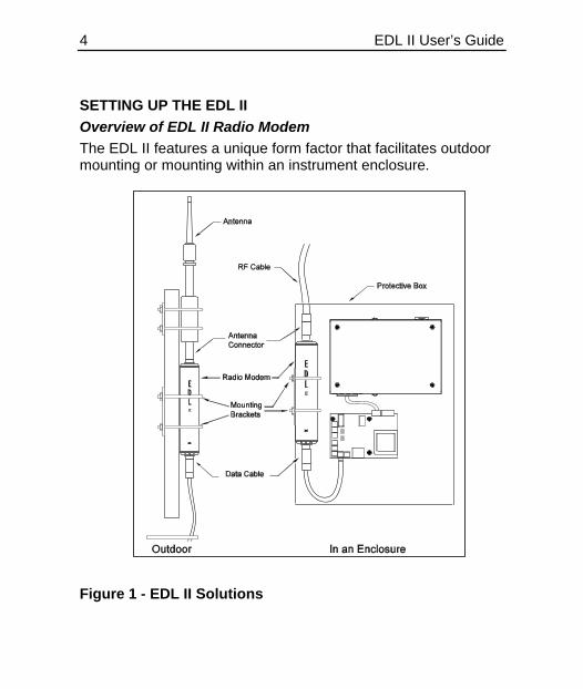
SETTING UP THE EDL II Overview of EDL II Radio Modem The EDL II features a unique form factor that facilitates outdoor mounting or mounting within an instrument enclosure.
Figure 1 - EDL II Solutions
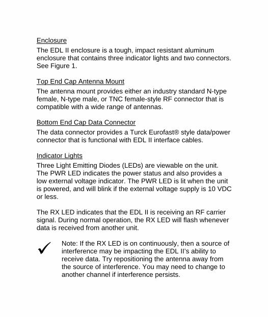
Enclosure The EDL II enclosure is a tough, impact resistant aluminum enclosure that contains three indicator lights and two connectors. See Figure 1. Top End Cap Antenna Mount The antenna mount provides either an industry standard N-type female, N-type male, or TNC female-style RF connector that is compatible with a wide range of antennas. Bottom End Cap Data Connector The data connector provides a Turck Eurofast® style data/power connector that is functional with EDL II interface cables. Indicator Lights Three Light Emitting Diodes (LEDs) are viewable on the unit. The PWR LED indicates the power status and also provides a low external voltage indicator. The PWR LED is lit when the unit is powered, and will blink if the external voltage supply is 10 VDC or less. The RX LED indicates that the EDL II is receiving an RF carrier signal. During normal operation, the RX LED will flash whenever data is received from another unit.
ü
Note: If the RX LED is on continuously, then a source of interference may be impacting the EDL II’s ability to receive data. Try repositioning the antenna away from the source of interference. You may need to change to another channel if interference persists.
6 EDL II User’s Guide
The TX LED indicates that the EDL II is transmitting. See Appendix A - Safety Information concerning antenna location during transmission. Connectors The EDL II features a compact, Turck-style, circular data/power connector. This connector is watertight and mates with the EDL II data cable. To connect the data cable to the EDL II, align the key mark on the plug with the key on the receptacle. Push the plug into the connector and screw the connector sleeve until tight. To remove the cable, unscrew the knurled section of the plug and then pull the plug out of the receptacle. Do not pull on the cable or directly on the plug unless the locking mechanism is retracted due to the possibility of damaging the cable. The EDL II features a variety of antenna connectors: 1) N-type: Male – standard (directional base antennas) 2) N-type: Female – directional base antennas 3) TNC: Female – direct “rubber duck” antenna connection See Appendix B - Pin-outs and Connectors for additional information.
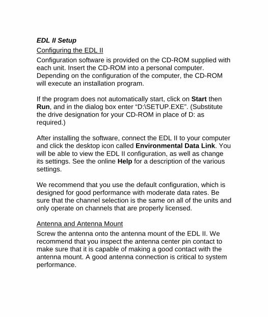
EDL II Setup Configuring the EDL II Configuration software is provided on the CD-ROM supplied with each unit. Insert the CD-ROM into a personal computer. Depending on the configuration of the computer, the CD-ROM will execute an installation program. If the program does not automatically start, click on Start then Run, and in the dialog box enter “D:\SETUP.EXE”. (Substitute the drive designation for your CD-ROM in place of D: as required.) After installing the software, connect the EDL II to your computer and click the desktop icon called Environmental Data Link. You will be able to view the EDL II configuration, as well as change its settings. See the online Help for a description of the various settings. We recommend that you use the default configuration, which is designed for good performance with moderate data rates. Be sure that the channel selection is the same on all of the units and only operate on channels that are properly licensed. Antenna and Antenna Mount Screw the antenna onto the antenna mount of the EDL II. We recommend that you inspect the antenna center pin contact to make sure that it is capable of making a good contact with the antenna mount. A good antenna connection is critical to system performance.
8 EDL II User’s Guide
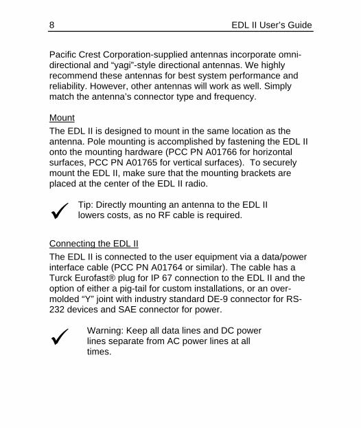
Pacific Crest Corporation-supplied antennas incorporate omni-directional and “yagi”-style directional antennas. We highly recommend these antennas for best system performance and reliability. However, other antennas will work as well. Simply match the antenna’s connector type and frequency. Mount The EDL II is designed to mount in the same location as the antenna. Pole mounting is accomplished by fastening the EDL II onto the mounting hardware (PCC PN A01766 for horizontal surfaces, PCC PN A01765 for vertical surfaces). To securely mount the EDL II, make sure that the mounting brackets are placed at the center of the EDL II radio.
ü
Tip: Directly mounting an antenna to the EDL II lowers costs, as no RF cable is required.
Connecting the EDL II The EDL II is connected to the user equipment via a data/power interface cable (PCC PN A01764 or similar). The cable has a Turck Eurofast® plug for IP 67 connection to the EDL II and the option of either a pig-tail for custom installations, or an over-molded “Y” joint with industry standard DE-9 connector for RS-232 devices and SAE connector for power.
ü
Warning: Keep all data lines and DC power lines separate from AC power lines at all times.
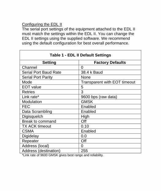
Configuring the EDL II The serial port settings of the equipment attached to the EDL II must match the settings within the EDL II. You can change the EDL II settings using the supplied software. We recommend using the default configuration for best overall performance.
Table 1 - EDL II Default Settings
Setting Factory Defaults Channel 0 Serial Port Baud Rate 38.4 k Baud Serial Port Parity None Mode Transparent with EOT timeout EOT value 5 Retries 3 Link rate* 9600 bps (raw data) Modulation GMSK FEC Enabled Data Scrambling Enabled Digisquelch High Break to command Off TX ACK timeout 0.10 CSMA Enabled Digidelay 0.0 Repeater Off Address (local) 0 Address (destination) 255 *Link rate of 9600 GMSK gives best range and reliability.
10 EDL II User’s Guide
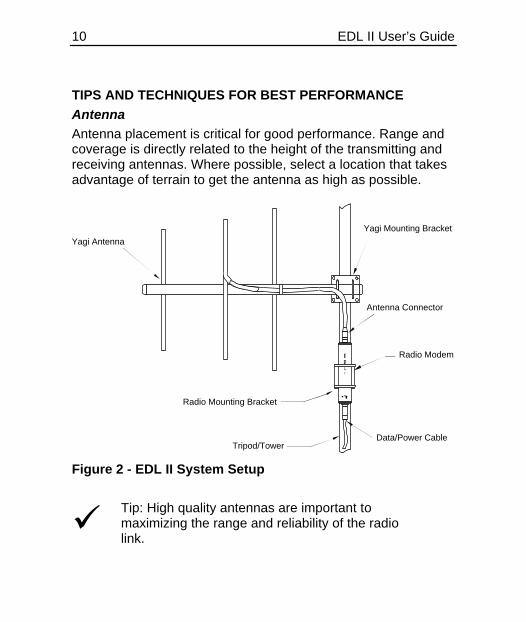
TIPS AND TECHNIQUES FOR BEST PERFORMANCE Antenna Antenna placement is critical for good performance. Range and coverage is directly related to the height of the transmitting and receiving antennas. Where possible, select a location that takes advantage of terrain to get the antenna as high as possible.
Radio Modem
Yagi Mounting Bracket
Data/Power Cable
Antenna Connector
Yagi Antenna
Tripod/Tower
Radio Mounting Bracket
Figure 2 - EDL II System Setup
ü
Tip: High quality antennas are important to maximizing the range and reliability of the radio link.
Power Supplies For battery-powered systems, maintain batteries in a fully- charged state. If the units are powered with a regulated power source, then make sure that the current sourcing capabilities meet the radio requirements. (See the Appendix C - Technical Specifications for power requirements.) Equipment Care Routine equipment care will prolong the life and reliability of your EDL II. Radio communication equipment is susceptible to damage from shock or environmental extremes. Inspect cables, connectors, and antennas periodically; replace if wear is present. Never open the EDL II unit, as there are no user-serviceable parts inside. Opening the EDL II enclosure invalidates the warranty provided. Error Codes The EDL II performs a variety of power-up and run-time tests to assure optimal operation. Tests include environmental as well as electrical measurements designed to avoid damage to the unit while maintaining adequate operation. In the event of an error condition, the RX and TX indicator lights blink in unison to provide error status. The indicators will blink a number of times, separated by a pause.
12 EDL II User’s Guide
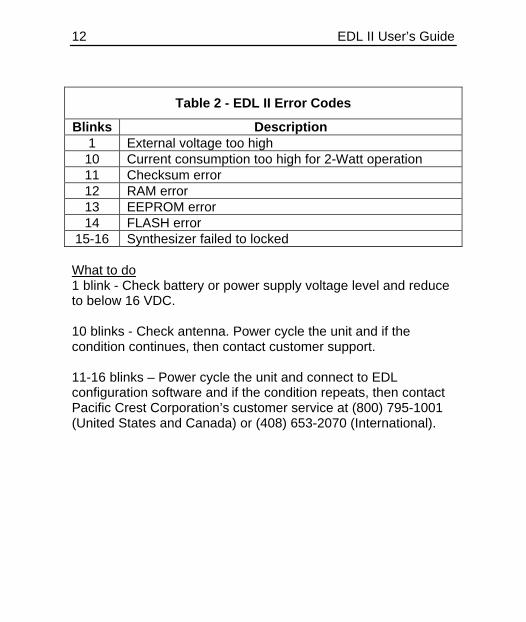
Table 2 - EDL II Error Codes
Blinks Description 1 External voltage too high 10 Current consumption too high for 2-Watt operation 11 Checksum error 12 RAM error 13 EEPROM error 14 FLASH error
15-16 Synthesizer failed to locked What to do 1 blink - Check battery or power supply voltage level and reduce to below 16 VDC. 10 blinks - Check antenna. Power cycle the unit and if the condition continues, then contact customer support. 11-16 blinks – Power cycle the unit and connect to EDL configuration software and if the condition repeats, then contact Pacific Crest Corporation’s customer service at (800) 795-1001 (United States and Canada) or (408) 653-2070 (International).
FCC RULES AND REGULATIONS Licensing Requirements It is the responsibility of the EDL II owner to comply with applicable rules and regulations concerning the operation of a radio transmitter. In the United States, the Federal Communications Commission (FCC) regulates the licensing of this equipment. Application for a license is made by submitting FCC Form 600 along with evidence of frequency coordination (if required) and applicable fees. Similar licensing requirements exist worldwide. Penalties for broadcasting without a license can be severe and may include the confiscation of your equipment.
ü
Warning: Always obey local licensing requirements and restrictions.
Equipment Compliances EDL II products have been tested and type-approved for operation in the U.S., Canada, China, and Europe. The EDL II products have also been tested and found compliant for type certification and approval in many other countries worldwide. For more information concerning our worldwide compliances, contact our customer service department.
ü
This device complies with Part 15 of the FCC rules. Operation is subject to the condition that this device does not cause harmful interference.
14 EDL II User’s Guide
Being Part of the RF Community Operation of a licensed radio product makes you a member of the RF community. Be aware that virtually all licensed frequencies are provided on a shared basis with other users. Frequencies are licensed with certain restrictions and limitations. For complete information, refer to Part 90, Title 47, of the U.S. Code of Federal Regulations, or other documents depending on the area of operation. Many frequencies are shared among data transmissions and voice users. In some circumstances, voice transmissions are given priority to voice users. You are responsible for complying with the requirements for shared channel use. Some operations are itinerant in that the system is moved on a frequent basis. For these types of systems, itinerant licenses are available. For fixed system installations, you should not use frequencies set aside for itinerant operations, but should coordinate a frequency based on the fixed area operation.
ü
Warning: Regulations differ from country to country, so please be aware of the local regulations prior to using the EDL II equipment.
Automatic Station Identification For operation in the United States, the FCC may require that radio transmitters used for environmental applications periodically broadcast a station identifier. The station identifier is the call sign assigned to you on the station license.
The EDL II supports the broadcast of station identification in a manner that meets the requirements of the FCC. Upon receipt of equipment, program your FCC call sign into the configuration of your EDL II using configuration software. This is only required for transmitters.
ü
Warning: Failure to transmit your station identification is in violation of FCC regulations. Use EDL II software and enter your FCC call sign to enable this capability.
Carrier Sense Multiple Access (CSMA) CSMA is a technology implemented in the EDL II to meet FCC transmitter requirements. CSMA holds off the radio transmission if the frequency is currently being used by a co-channel user. On occasion, you may note that the radio broadcasts stop for short periods of time. Most often, this is a case of co-channel interference and the EDL II is holding off broadcasts due to the FCC-mandated CSMA. Heavy co-channel use may limit the ability of the EDL II to transmit the required information. In areas of heavy co-channel usage you may wish to obtain licensing for alternative channels. We recommend monitoring a particular frequency prior to licensing to determine usability. Ask your frequency coordinator about monitoring the frequency prior to operating. You can monitor a frequency using the EDL II as an indicator of activity (observe the RX LED) or you can use an inexpensive radio scanner.
This page intentionally left blank.
SERVICE AND SUPPORT Contacting Pacific Crest Corporation Quality, innovation and service are the hallmarks of Pacific Crest Corporation. We provide easy access to our customer service department to keep you running efficiently. Phone: 1-800-795-1001 (U.S. & Canada toll free) (408) 653-2070 (International) +31 (0) 725 764 175 (Europe) (408) 748-9984 (Fax) E-mail: [email protected][email protected] Web: www.pacificcrest.com Mail: Pacific Crest Corporation 990 Richard Avenue, Suite 110 Santa Clara, CA 95050 Support hours are 8 AM to 5 PM Pacific Standard Time. Please visit our web site for up-to-date news and product announcements. Firmware and software upgrades are also available from our web site, in most cases free of charge.
18 EDL II User’s Guide
WARRANTY One-Year Limited Warranty This warranty gives you specific legal rights. You may also have other rights, which vary from state to state or area to area. Pacific Crest Corporation warrants EDL II family products, exclusive of cables and batteries, against defects in materials and workmanship for a period of one year from receipt by the end user. Cables and batteries carry a 90-day warranty against defects in materials and workmanship. Exclusions Should Pacific Crest Corporation be unable to repair or replace the product within a reasonable amount of time then a refund of the purchase price may be given upon return of the product within its warranty period. The warranty on your EDL II radio modem shall not apply to defects resulting from: • Improper or inadequate maintenance by the customer • Unauthorized modification or misuse • Operation outside of the environment specifications • Negligence or misuse Warranty Limitations This warranty set forth above is exclusive and no other warranty, whether written or oral, is expressed or implied. Pacific Crest Corporation specifically disclaims the implied warranties of merchantability and fitness for a particular purpose.
This page intentionally left blank.
20 EDL II User’s Guide
APPENDIX A - SAFETY INFORMATION Exposure to Radio Frequency Energy The EDL II radio modem products are designed to comply with the following national and international standards and guidelines regarding exposure of human beings to radio frequency electromagnetic energy: • FCC Report and Order FCC 96-326 (August 1996) • American National Standards Institute (C95.3-1992) • National Council on Radiation Protection and Measurement
(NCRP - 1986) • International Commission on Non-ionizing Radiation
Protection (ICNRP - 1986) • European Committee for Electrotechnical Standardization
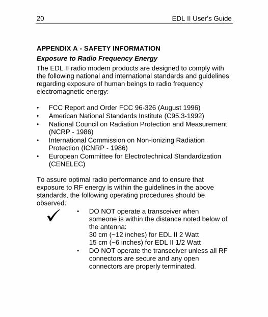
(CENELEC) To assure optimal radio performance and to ensure that exposure to RF energy is within the guidelines in the above standards, the following operating procedures should be observed:
ü
• DO NOT operate a transceiver when someone is within the distance noted below of the antenna: 30 cm (~12 inches) for EDL II 2 Watt 15 cm (~6 inches) for EDL II 1/2 Watt
• DO NOT operate the transceiver unless all RF connectors are secure and any open connectors are properly terminated.
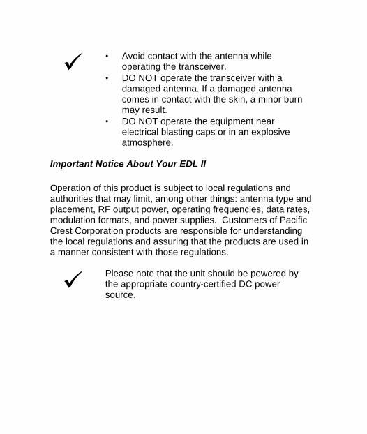
ü
• Avoid contact with the antenna while operating the transceiver.
• DO NOT operate the transceiver with a damaged antenna. If a damaged antenna comes in contact with the skin, a minor burn may result.
• DO NOT operate the equipment near electrical blasting caps or in an explosive atmosphere.
Important Notice About Your EDL II Operation of this product is subject to local regulations and authorities that may limit, among other things: antenna type and placement, RF output power, operating frequencies, data rates, modulation formats, and power supplies. Customers of Pacific Crest Corporation products are responsible for understanding the local regulations and assuring that the products are used in a manner consistent with those regulations.
ü
Please note that the unit should be powered by the appropriate country-certified DC power source.
22 EDL II User’s Guide
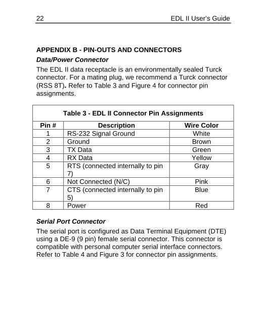
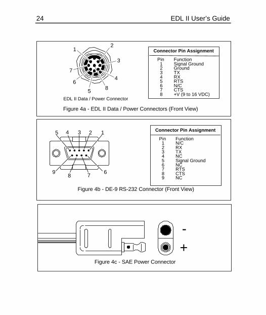
APPENDIX B - PIN-OUTS AND CONNECTORS Data/Power Connector The EDL II data receptacle is an environmentally sealed Turck connector. For a mating plug, we recommend a Turck connector (RSS 8T). Refer to Table 3 and Figure 4 for connector pin assignments.
Table 3 - EDL II Connector Pin Assignments
Pin # Description Wire Color 1 RS-232 Signal Ground White 2 Ground Brown 3 TX Data Green 4 RX Data Yellow 5 RTS (connected internally to pin
7) Gray
6 Not Connected (N/C) Pink 7 CTS (connected internally to pin
5) Blue
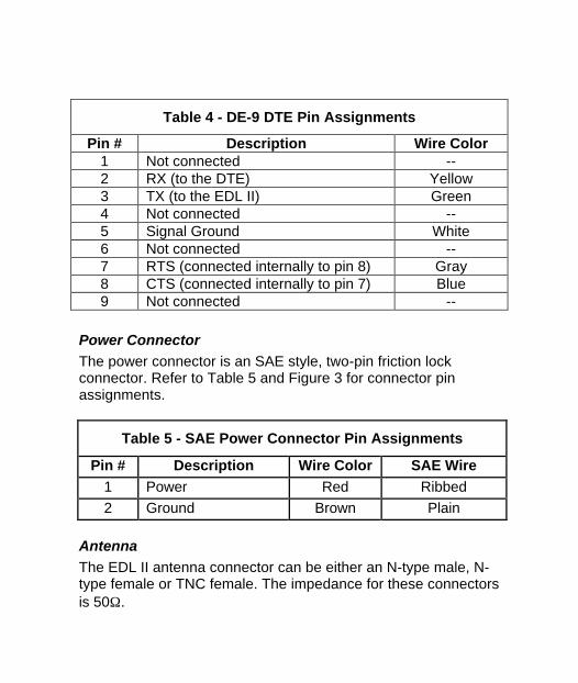
8 Power Red Serial Port Connector The serial port is configured as Data Terminal Equipment (DTE) using a DE-9 (9 pin) female serial connector. This connector is compatible with personal computer serial interface connectors. Refer to Table 4 and Figure 3 for connector pin assignments.
Table 4 - DE-9 DTE Pin Assignments
Pin # Description Wire Color 1 Not connected -- 2 RX (to the DTE) Yellow 3 TX (to the EDL II) Green 4 Not connected -- 5 Signal Ground White 6 Not connected -- 7 RTS (connected internally to pin 8) Gray 8 CTS (connected internally to pin 7) Blue 9 Not connected --
Power Connector The power connector is an SAE style, two-pin friction lock connector. Refer to Table 5 and Figure 3 for connector pin assignments.
Table 5 - SAE Power Connector Pin Assignments
Pin # Description Wire Color SAE Wire 1 Power Red Ribbed 2 Ground Brown Plain
Antenna The EDL II antenna connector can be either an N-type male, N-type female or TNC female. The impedance for these connectors is 50Ω.
24 EDL II User’s Guide
Figure 4a - EDL II Data / Power Connectors (Front View)
EDL II Data / Power Connector
Connector Pin Assignment Pin Function 1 Signal Ground 2 Ground 3 TX 4 RX 5 RTS 6 N/C 7 CTS 8 +V (9 to 16 VDC)
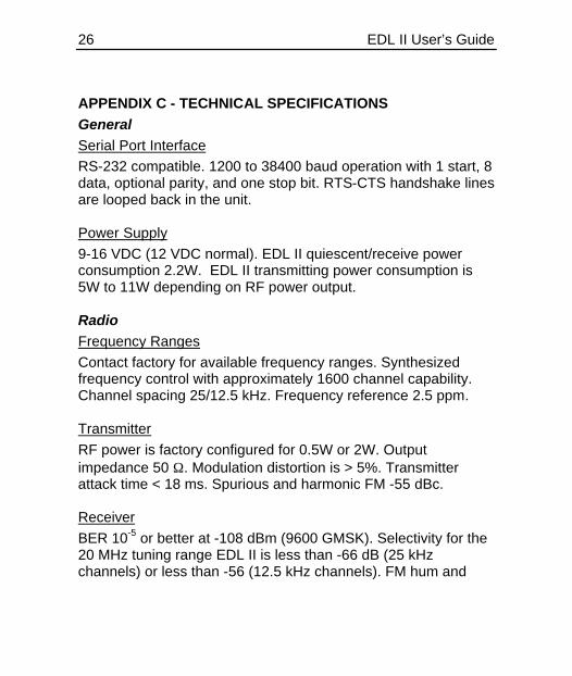
APPENDIX C - TECHNICAL SPECIFICATIONS General Serial Port Interface RS-232 compatible. 1200 to 38400 baud operation with 1 start, 8 data, optional parity, and one stop bit. RTS-CTS handshake lines are looped back in the unit. Power Supply 9-16 VDC (12 VDC normal). EDL II quiescent/receive power consumption 2.2W. EDL II transmitting power consumption is 5W to 11W depending on RF power output. Radio Frequency Ranges Contact factory for available frequency ranges. Synthesized frequency control with approximately 1600 channel capability. Channel spacing 25/12.5 kHz. Frequency reference 2.5 ppm. Transmitter RF power is factory configured for 0.5W or 2W. Output impedance 50 Ω. Modulation distortion is > 5%. Transmitter attack time < 18 ms. Spurious and harmonic FM -55 dBc. Receiver BER 10-5 or better at -108 dBm (9600 GMSK). Selectivity for the 20 MHz tuning range EDL II is less than -66 dB (25 kHz channels) or less than -56 (12.5 kHz channels). FM hum and
noise -40 dB. Conducted spurious -65 dB. Carrier detect attack time 2 ms. Modem Transmission Rate 19,200 or 9,600 bits per second (Four-level FSK) 9,600 or 4,800 bits per second (GMSK) Transmission Protocols Transparent, packet switched, auto-repeater, and fast asynchronous. Forward Error Correction and Detection With FEC enabled, data is then encoded by a block code. The data is interleaved, giving burst error correction capabilities. 16-bit CRCs are generated and sent with every block of data providing 100 percent error detection for burst errors shorter than 16 bits, and 99.9984 percent detection of all other burst errors. Modulation Gaussian Minimum Shift Keying (GMSK) with BT of 0.5 (4800, 9600 bps link rate). Four-level FSK* (9600, 19200 bps link rate). *Note: Not available for use in all areas. Consult your local FCC regulatory representative for additional information.
28 EDL II User’s Guide
Environmental Size 8.35" length x 1.63" diameter (21.21 cm length x 4.10 cm diameter) Weight 0.65 lbs (0.30 Kg) Protection and Vibration Per IEC 60529 I.P. 67 Dust-tight and waterproof Per IEC 945 Chapter 8:
Operating -22° to 140° F (-30° to 60° C) Storage -67° to 185° F (-55° to 85° C) Compliance United States: Type-approved CFR Title 47 Part 90 Canada: Type-approved per RSS.119 China: Type-approved per CMII ID: 2001FJ0131 Europe: Type-approved per ETS 300 220 or ETS 300 113 Other countries: Contact the factory.