47
A concept on the process of
| Date post: | 07-Aug-2015 |
| Category: |
Documents |
| Upload: | rituraj-dhar |
| View: | 48 times |
| Download: | 2 times |
A concept on the process of

By:- Syed Javed Iftikar Ahmed Arnav Dutta Naresh Pradhan Rituraj Dhar Trinayan Deka Biswajit Borah Neelutpal Rajkhowa Abhishek Pradhan Aditya Bimal
INTRODUCTION Electric discharge machining (EDM),
sometimes colloquially also referred to as spark machining, spark eroding, burning, die sinking or wire erosion,[is a manufacturing process whereby a desired shape is obtained using electrical discharges (sparks). Material is removed from the workpiece by a series of rapidly recurring current discharges between two electrodes, separated by a dielectric liquid and subject to an electric voltage. One of the electrodes is called the tool-electrode, or simply the ‘tool’ or ‘electrode’, while the other is called the workpiece-electrode, or ‘workpiece’.
When the distance between the two electrodes is reduced, the intensity of the electric field in the volume between the electrodes becomes greater than the strength of the dielectric (at least in some point(s)), which breaks, allowing current to flow between the two electrodes. This phenomenon is the same as the breakdown of a capacitor (condenser) (see also breakdown voltage). As a result, material is removed from both the electrodes. Once the current flow stops (or it is stopped - depending on the type of generator), new liquid dielectric is usually conveyed into the inter-electrode volume enabling the solid particles (debris) to be carried away and the insulating proprieties of the dielectric to be restored. Adding new liquid dielectric in the inter-electrode volume is commonly referred to as flushing. Also, after a current flow, a difference of potential between the two electrodes is restored to what it was before the breakdown, so that a new liquid dielectric breakdown can occur.
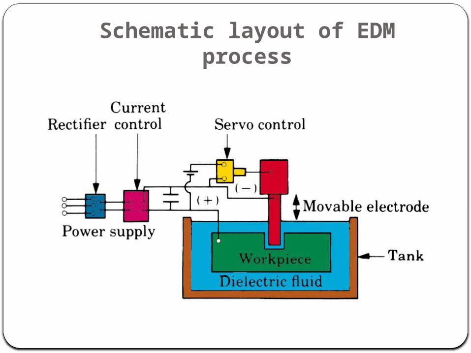
Schematic layout of EDM process
WORKING PRINCIPLE OF EDMThe working principle of EDM process is based on the thermoelectric energy. This energy is created between a workpiece and an electrode submerged in a dielectric fluid with the passage of electric current. The workpiece and the electrode are separated by a specific small gap called spark gap. Pulsed arc discharges occur in this gap filled with an insulating medium, preferably a dielectric liquid like hydrocarbon oil or de-ionized (de-mineralized) water . Schumacher described the technique of material erosion employed in EDM as still arguable. This is because ignition of electrical discharges in a dirty, liquid filled gap, when applying EDM, is mostly interpreted as ion action identical as found by physical research of discharges in air or in vacuum as well as with investigations on the breakthrough strength of insulating hydrocarbon liquids.

The working principle of EDM is shown in Fig. 1. This technique has been developed in the late 1940s . The electrode moves toward the workpiece reducing the spark gap so that the applied voltage is high enough to ionize the dielectric fluid . Short duration discharges are generated in a liquid dielectric gap, which separates electrode and workpiece. The material is removed from tool and workpiece with the erosive effect of the electrical discharges . The dielectric fluid serves the purpose to concentrate the discharge energy into a channel of very small cross sectional areas. It also cools the two electrodes, and flushes away the products of machining from the gap. The electrical resistance of the dielectric influences the discharge energy and the time of spark initiation . Low resistance results in early discharge. If resistance is large, the capacitor will attain a higher charge value before initiation of discharge.
A servo system is employed which compares the gap voltage with a reference value and to ensure that the electrode moves at a proper rate to maintain the right spark gap, and also to retract the electrode if shortcircuiting occurs. When the measured average gap voltage is higher than that of the servo reference voltage, preset by the operator, the feed speed increases. On the contrary, the feed speed decreases or the electrode is retracted when the average gap voltage is lower than the reference voltage, which is the case for smaller gap widths resulting in a smaller ignition delay. Thus short circuits caused by debris particles and humps of discharge a crater are avoided. Also quick changes in the working surface area, when tool shapes are complicated, does not result in hazardous machining. In some cases, the average ignition delay time is used in place of the average gap voltage to monitor the gap width [14] The RC circuit employed in EDM did not give good material removal rate, and higher material removal rate was possible only by sacrificing surface finish. A major portion of the time of machining was spent on charging the capacitors as shown in Fig. 2. [15].
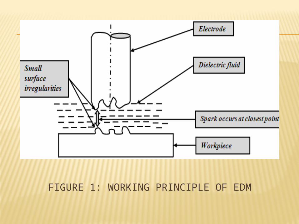
FIGURE 1: WORKING PRINCIPLE OF EDM
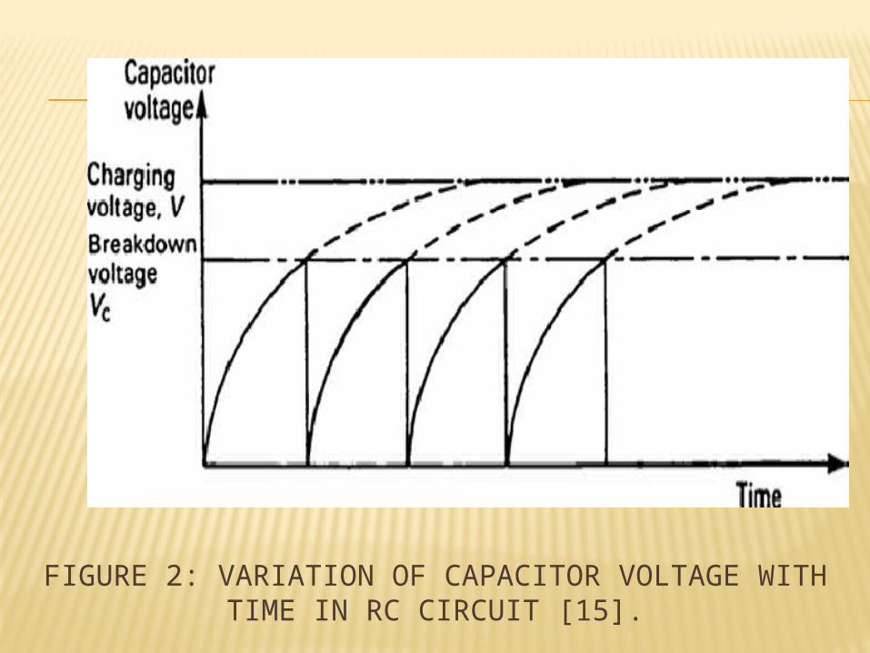
FIGURE 2: VARIATION OF CAPACITOR VOLTAGE WITH TIME IN RC CIRCUIT [15].

FIGURE 3: SCHEMATIC VIEW OF DISCHARGE GAP [13]

Fig. 3 shows a systematic view of EDM spark spot [13]. The arc column diameter increases with the passage of time and equal to the diameter of the generated discharge crater . In the spark gap electrode materials and dielectric liquid are evaporated, molecules are dissociated, and atoms are ionized, resulting in a rapid expansion of the bubble from dielectric fluid. Since the expansion is restricted by the inertia and viscosity of the dielectric, the pressure inside the bubble becomes extremely high and the boundary between the bubble and liquid expands withthe velocity of several tens m/s . It is still believed that the dielectric liquid plays a significant role in material removal because the high pressure and velocity field in the bubble may serve as the dynamics of the material removal in EDM
In this process there is no direct contact between the electrode and the workpiece thus eliminating mechanical stresses, chatter and vibration problems during machining . Trends on activities carried out by researchers depend on the interest of the researchers and the availability of the technology. Rajurkar has indicated some future trends activities in EDM: machining advanced materials, mirror surface finish using powder additives, ultrasonic-assisted EDM and control and automation.

Process Parameters and Performance Measures
Pulse Duration (Ton): It is the duration of time measured in micro seconds. During this time period the current is allowed to through the electrode towards the work material within a short gap known as spark gap. Metal removal is directly proportional to the amount of energy applied during the on time period . Pulse duration is also known as pulse on time and the sparks are generated at certain frequency. Material removal rate depends on longer or shorter pulse on time period. Longer pulse duration improves removal rate of debris from the machined area which also effects on the wear behavior of electrode. As in EDM process erosion takes place in the form of melting and vaporization of both the tool and work material at the same time period, so with longer pulse duration more material has to be melt and vaporize. The resulting crater produced will be broader as comparison to the shorter pulse on time. But, in some experimental research work it has been proved that optimal pulse duration gives higher performance measures.
Electrical Parameters
It conclude all that MRR can not be increased by increasing the Pulse on time, a suitable combination of peak current is also needed for increasing rate of removing unwanted material from the work piece. At constant current and constant duty factor, the MRR is decreased with increase in pulse on time . This is due to the reason because of short pulses cause less vaporization, where as long pulse duration causes the plasma channel to expand rapidly. This expansion of plasma channel cause less energydensity on the work material, which is not sufficient to melt and vaporize the work material. It was alsoconcluded by the researchers that with increase of pulse duration, surface roughness decreased, hardness of work material, crack length, crack width and the thickness of recast layer increased.Fig.3.0

Fig.3.0 Actual profile of single EDM pulse (Fuller, 1996)ISSN:

Pulse Interval (Toff):
It is the waiting interval time period during two pulses on time periods. In fig.1.7, it is the duration of time in which no machining takes place (idle time period) and it allows the melt material to vaporize and to remove from setting. This parameter is to affect the speed and the stability of the cut. If the off-time is too short, it improves MRR but it will because more sparks to be unstable in the machining zone .Kansal et al. result out that increase in pulse interval time decreases the MRR. Saha et al. reported out that for small value of pulse interval time period, the MRR was low, but with further increase MRR increases. MRR was dropped slowly with increase in pulse interval time. This is due to very short pulse interval the probability of arcing is larger because dielectric in the gap does not recover its dielectric strength. O.A. Abu Zeid investigated the role of voltage, pulse off time in the electro discharge machined AISI T1 high speed steel . The researcher concluded that the MRR is not so much sensitive to pulse interval time changes at low pulse on time in finish machining.

Fig.4.0 Pulse wave form of pulse generator
Electrode gap (spark gap):
It is the distance between the electrode and the part during the process of EDM. An electro-mechanical and hydraulic systems are used to respond to average gap voltage. To obtain good performance and gap stability a suitable gap should be maintained. For the reaction speed, it must obtain a high speed so that it can respond to short circuits or even open gap circuits. Gap width is not measured directly, but can be inferred from the average gap voltage
Non Electrical Parameters
Non-electrical parameters such as the Rotational movement of electrode, flushing of dielectric fluid and aspect ratio ( tool shape) together play a significant role in delivering optimal performance measures. This section discusses the effects of non-electrical parameters on the various performance measures.
It is the rotational effect of cylindrical (pin shaped) or disc shaped electrode tool measured in revolution/minute. The rotational movement of electrode is normal to the work surface and with increasing the speed, a centrifugal force is generated causes more debris to remove faster from the machining zone. According to Mohan et al., the centrifugal force generated throws a layer of dielectric in to the machining gap, induces an atmosphere for better surface finish, prevent arching and improves MRR. Soni and Chakraverti compared the various performance measures of rotating electrode with the stationary electrode. The results concluded an improvement in MRR due to the better flushing action and sparking efficiency with little tool wear but the surface finish was improved.
•Rotation of Tool Electrode:
Flushing removes eroded particles from the gap for efficient cutting and improved surface finish of machined material. Flushing also enables fresh dielectric oil flow into the gap and cools both the electrode and the work piece. Basic characteristics required for dielectric used in EDM are high dielectric strength and quick recovery after breakdown .There variations of EDM processes can be classified according to the type of dielectric fluid used. Most dielectric media are hydrocarbon compounds and water. The hydrocarbon compounds are in the form of refined oil; better known as kerosene.
•Injection flushing:

While the fluid properties are essential, the correct fluid circulating methodology is also important. The dielectric fluid not only forms a dielectric barrier for the spark between the work piece and the electrode but also cools the eroded particles between the work piece and the electrode. The pressurized fluid flushes out the eroded gap particles and remove the debris from the fluid medium by causing the fluid to pass through a filter system .During the investigation of EDM of Ti 6Al 4V, Chen et al. [35] found that the MRR was greater and the relative EWR is lower, when using 16 distilled water as dielectric solution.
Tool geometry is concerned with the shape of the tool electrodes.ie. Square, rectangle, cylindrical, circular.etc. The ratio of length /diameter of any shaped feature of material. In case of rotating disk electrode the ratio becomes thickness/diameter. Murali et al [36] used graphite foil for straight grooving operation instead of pin shaped electrode. An aspect ratio of 2.3 was achieved by using FAST technique (Foil as tool electrode) which was improved to 8 by implementing GAME (Gravity assisted Micro EDM). Singh et al. uses square and rectangular shaped electrodes having aspect ratio of 1.0 and 0.6 for machining 6061Al/Al2O3P composite .It concluded that shape of the electrode effects EWR. The tool having less aspect ratio gave higher value of EWR.Thus with increasing the size of electrode more good performance of ED Machining takes place.
•Tool Geometry:
Engineering materials having higher thermal conductivity and melting point are used as a tool material for EDM process of machining . Copper, graphite, copper-tungsten, silver tungsten, copper graphite and brass are used as a tool material (electrode) in EDM. They all have good wear characteristics, better conductivity, and better sparking conditions for machining. Copper with 5% tellurium, added forbetter machining properties. Tungsten resist wear better than copper and brass .Brass ensures stable sparking conditions and is normally used for specialized applications such as drilling of small holes where the high electrode wear is acceptable (Metals Handbook, 1989). The factors that effect selection ofelectrode material include metal removal rate, wear resistance, desired surface finish, cost of electrode material manufacture and material and characteristics of work material to be machined.
•Tool Material (Electrode):
Material removal mechanism• The first serious attempt of providing a physical explanation of the
material removal during electric discharge machining is perhaps that of Van Dijk.Van Dijk presented a thermal model together with a computational simulation to explain the phenomena between the electrodes during electric discharge machining. However, as Van Dijk himself admitted in his study, the number of assumptions made to overcome the lack of experimental data at that time was quite significant.
• Further models of what occurs during electric discharge machining in terms of heat transfer were developed in the late eighties and early nineties, including an investigation at Texas A&M University with the support of AGIE, now Agiecharmilles. It resulted in three scholarly papers: the first presenting a thermal model of material removal on the cathode, the second presenting a thermal model for the erosion occurring on the anode and the third introducing a model describing the plasma channel formed during the passage of the discharge current through the dielectric liquid.Validation of these models is supported by experimental data provided by AGIE.
These models give the most authoritative support for the claim that EDM is a thermal process, removing material from the two electrodes because of melting and/or vaporization, along with pressure dynamics established in the spark-gap by the collapsing of the plasma channel. However, for small discharge energies the models are inadequate to explain the experimental data. All these models hinge on a number of assumptions from such disparate research areas as submarine explosions, discharges in gases, and failure of transformers, so it is not surprising that alternative models have been proposed more recently in the literature trying to explain the EDM process.Among these, the model from Singh and Ghosh reconnects the removal of material from the electrode to the presence of an electrical force on the surface of the electrode that could mechanically remove material and create the craters. This would be possible because the material on the surface has altered mechanical properties due to an increased temperature caused by the passage of electric current. The authors' simulations showed how they might explain EDM better than a thermal model (melting and/or evaporation), especially for small discharge energies, which are typically used in μ-EDM and in finishing operations.
Given the many available models, it appears that the material removal mechanism in EDM is not yet well understood and that further investigation is necessary to clarify it, especially considering the lack of experimental scientific evidence to build and validate the current EDM models. This explains an increased current research effort in related experimental techniques.
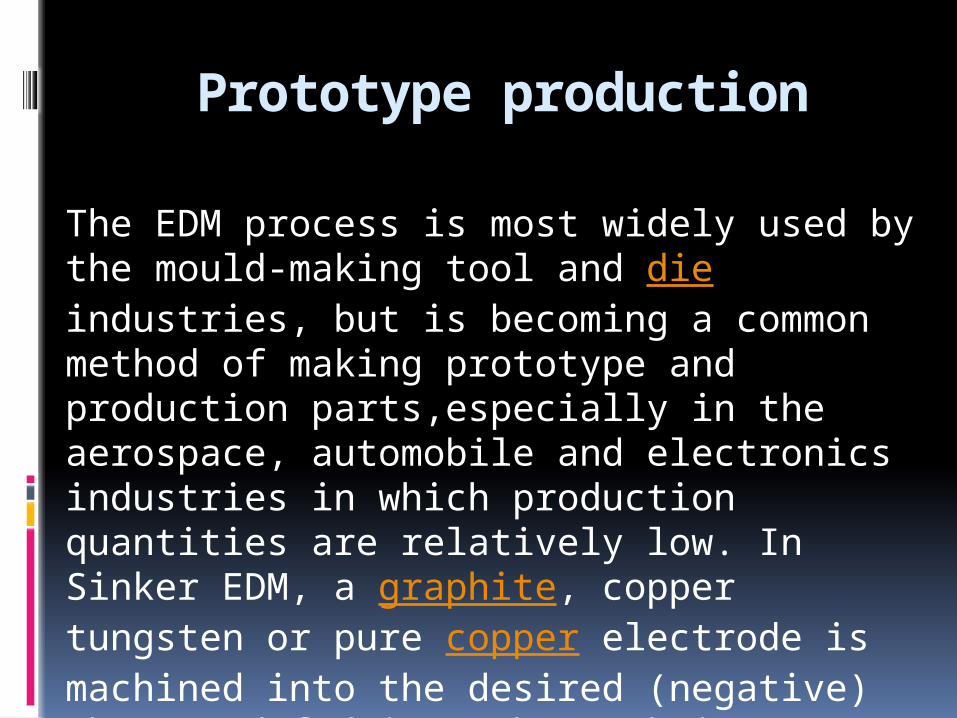
Prototype production
The EDM process is most widely used by the mould-making tool and die industries, but is becoming a common method of making prototype and production parts,especially in the aerospace, automobile and electronics industries in which production quantities are relatively low. In Sinker EDM, a graphite, copper tungsten or pure copper electrode is machined into the desired (negative) shape and fed into the workpiece on the end of a vertical ram.
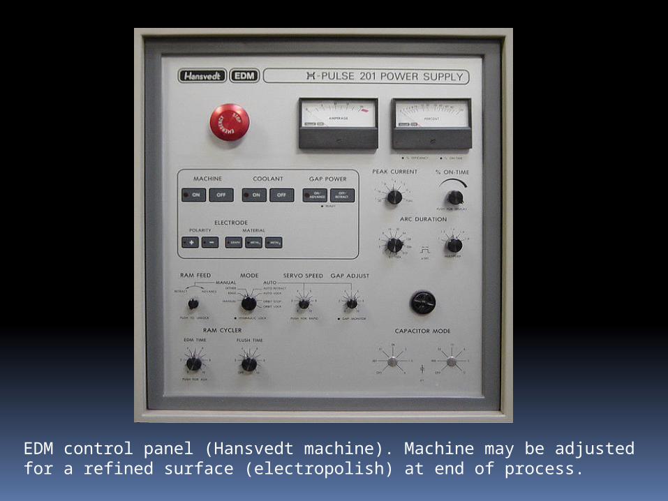
EDM control panel (Hansvedt machine). Machine may be adjusted for a refined surface (electropolish) at end of process.
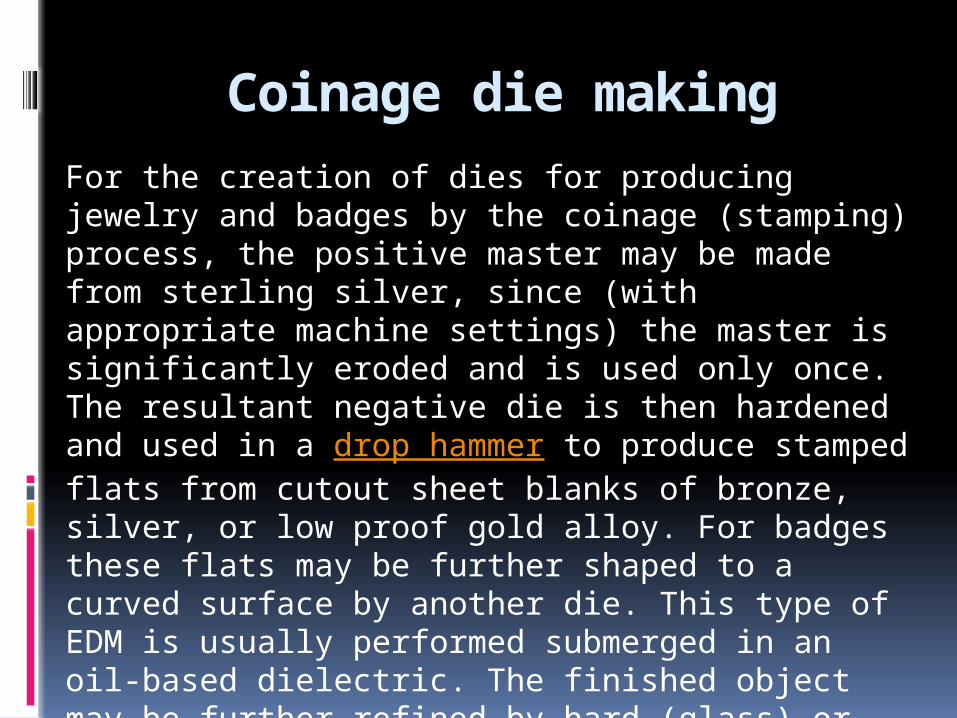
Coinage die makingFor the creation of dies for producing jewelry and badges by the coinage (stamping) process, the positive master may be made from sterling silver, since (with appropriate machine settings) the master is significantly eroded and is used only once. The resultant negative die is then hardened and used in a drop hammer to produce stamped flats from cutout sheet blanks of bronze, silver, or low proof gold alloy. For badges these flats may be further shaped to a curved surface by another die. This type of EDM is usually performed submerged in an oil-based dielectric. The finished object may be further refined by hard (glass) or soft (paint) enameling and/or electroplated with pure gold or nickel. Softer materials such as silver may be hand engraved as a refinement.
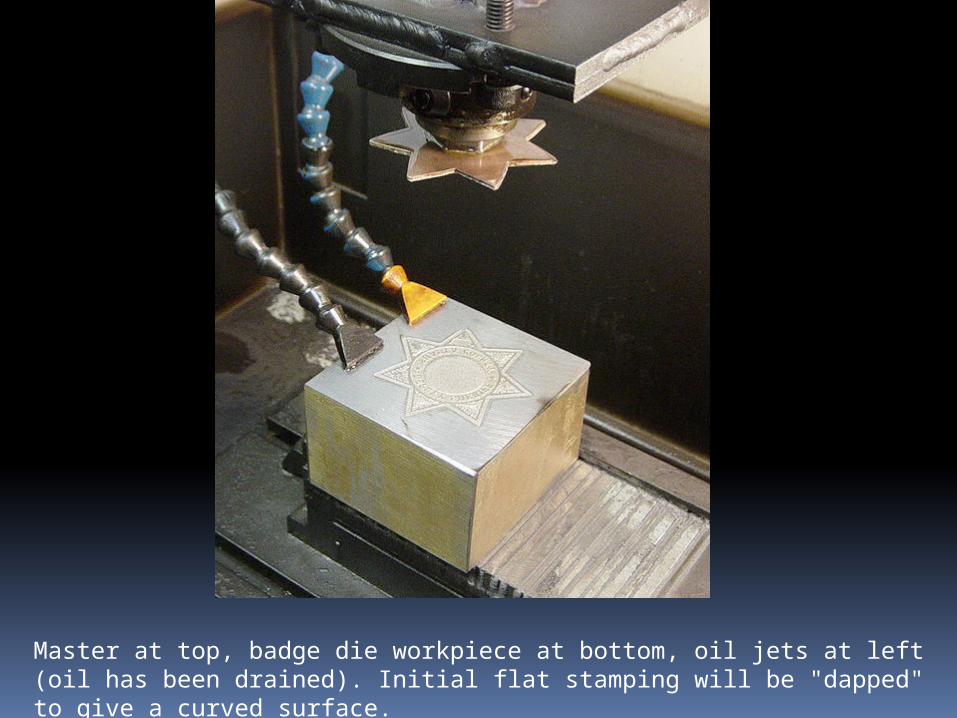
Master at top, badge die workpiece at bottom, oil jets at left (oil has been drained). Initial flat stamping will be "dapped" to give a curved surface.
Small hole drilling
Small hole drilling EDM is used in a variety of applications.On wire-cut EDM machines, small hole drilling EDM is used to make a through hole in a workpiece in through which to thread the wire for the wire-cut EDM operation. A separate EDM head specifically for small hole drilling is mounted on a wire-cut machine and allows large hardened plates to have finished parts eroded from them as needed and without pre-drilling.Small hole EDM is used to drill rows of holes into the leading and trailing edges of turbine blades used in jet engines. Gas flow through these small holes allows the engines to use higher temperatures than otherwise possible. The high-temperature, very hard, single crystal alloys employed in these blades makes conventional machining of these holes with high aspect ratio extremely difficult, if not impossible.
Small hole EDM is also used to create microscopic orifices for fuel system components, spinnerets for synthetic fibers such as rayon, and other applications.There are also stand-alone small hole drilling EDM machines with an x–y axis also known as a super drill or hole popper that can machine blind or through holes. EDM drills bore holes with a long brass or copper tube electrode that rotates in a chuck with a constant flow of distilled or deionized water flowing through the electrode as a flushing agent and dielectric. The electrode tubes operate like the wire in wire-cut EDM machines, having a spark gap and wear rate. Some small-hole drilling EDMs are able to drill through 100 mm of soft or through hardened steel in less than 10 seconds, averaging 50% to 80% wear rate. Holes of 0.3 mm to 6.1 mm can be achieved in this drilling operation. Brass electrodes are easier to machine but are not recommended for wire-cut operations due to eroded brass particles causing "brass on brass" wire breakage, therefore copper is recommended.
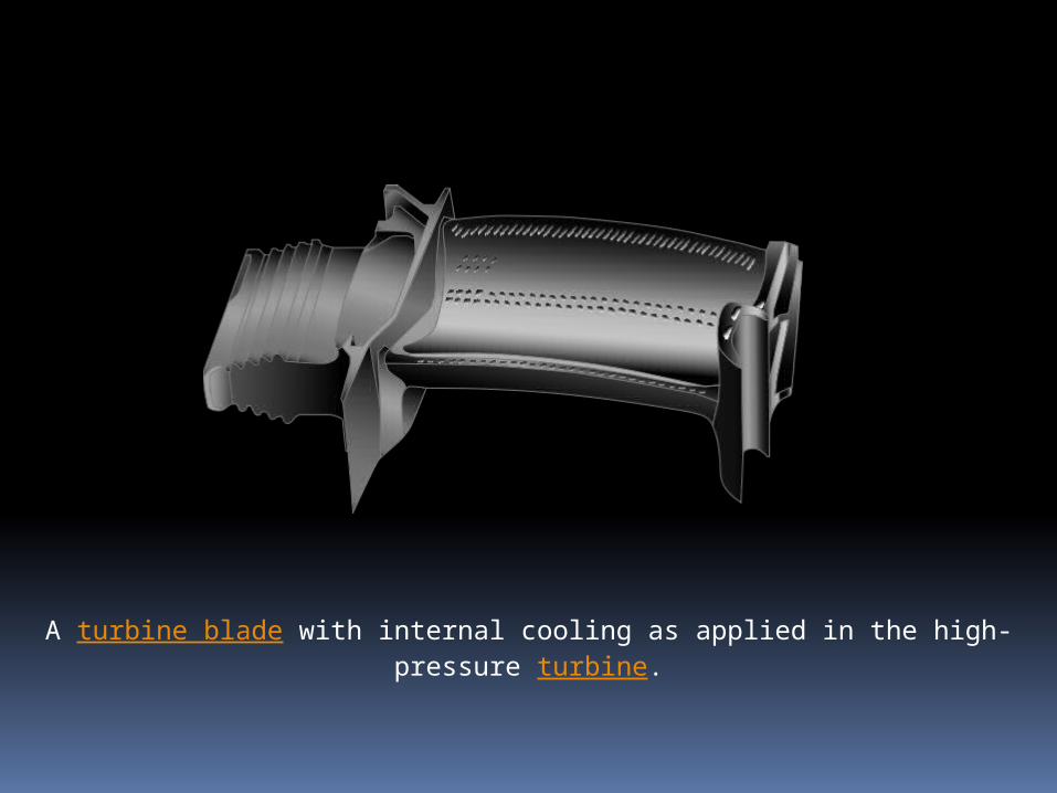
A turbine blade with internal cooling as applied in the high-pressure turbine.

Some modern machining models
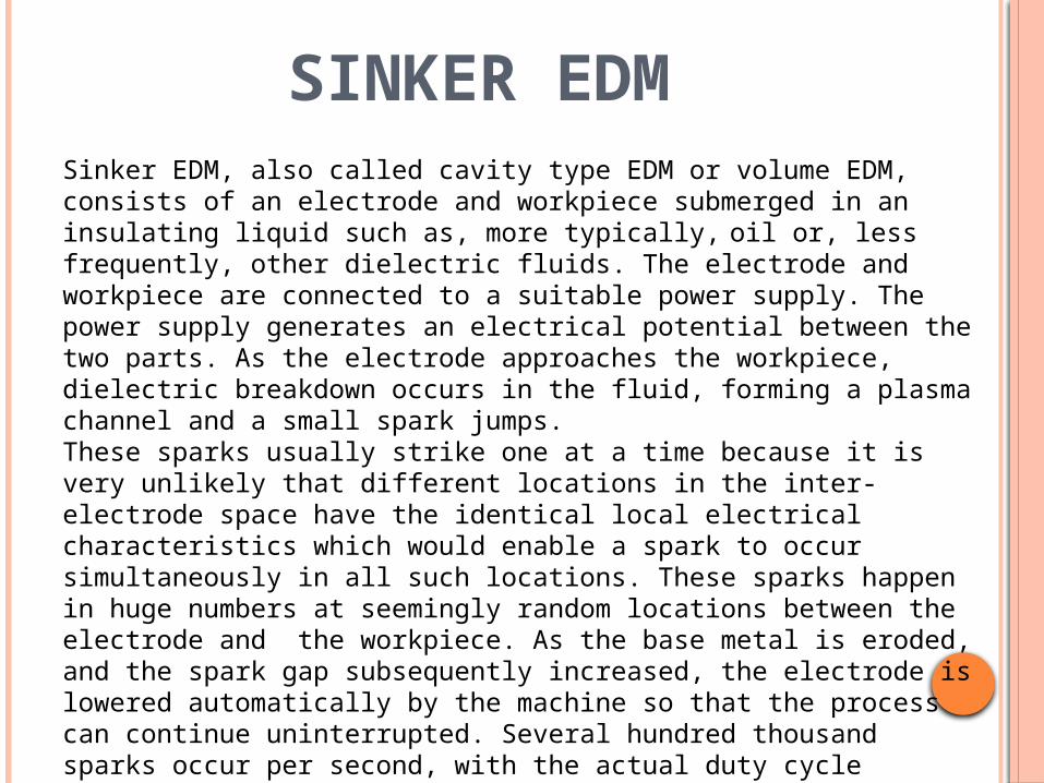
SINKER EDMSinker EDM, also called cavity type EDM or volume EDM, consists of an electrode and workpiece submerged in an insulating liquid such as, more typically, oil or, less frequently, other dielectric fluids. The electrode and workpiece are connected to a suitable power supply. The power supply generates an electrical potential between the two parts. As the electrode approaches the workpiece, dielectric breakdown occurs in the fluid, forming a plasma channel and a small spark jumps.These sparks usually strike one at a time because it is very unlikely that different locations in the inter-electrode space have the identical local electrical characteristics which would enable a spark to occur simultaneously in all such locations. These sparks happen in huge numbers at seemingly random locations between the electrode and the workpiece. As the base metal is eroded, and the spark gap subsequently increased, the electrode is lowered automatically by the machine so that the process can continue uninterrupted. Several hundred thousand sparks occur per second, with the actual duty cycle carefully controlled by the setup parameters. These controlling cycles are sometimes known as "on time" and "off time", which are more formally defined in the literature.
The on time setting determines the length or duration of the spark. Hence, a longer on time produces a deeper cavity for that spark and all subsequent sparks for that cycle, creating a rougher finish on the workpiece. The reverse is true for a shorter on time. Off time is the period of time that one spark is replaced by another. A longer off time, for example, allows the flushing of dielectric fluid through a nozzle to clean out the eroded debris, thereby avoiding a short circuit. These settings can be maintained in micro seconds. The typical part geometry is a complex 3D shape, often with small or odd shaped angles. Vertical, orbital, vectorial, directional, helical, conical, rotational, spin and indexing machining cycles are also used.
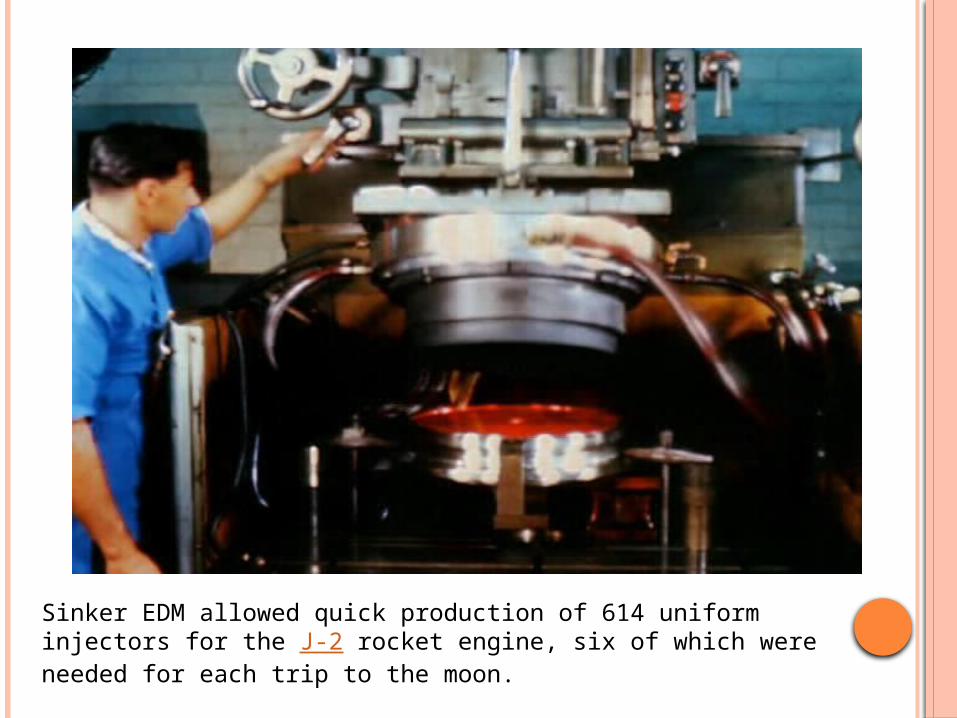
Sinker EDM allowed quick production of 614 uniform injectors for the J-2 rocket engine, six of which were needed for each trip to the moon.
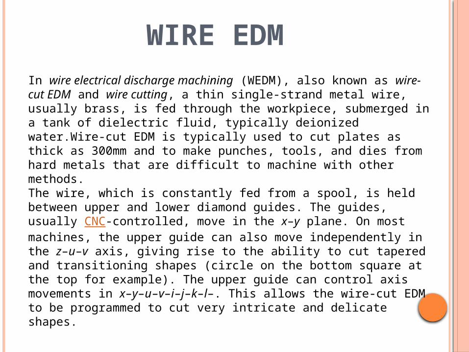
WIRE EDMIn wire electrical discharge machining (WEDM), also known as wire-cut EDM and wire cutting, a thin single-strand metal wire, usually brass, is fed through the workpiece, submerged in a tank of dielectric fluid, typically deionized water.Wire-cut EDM is typically used to cut plates as thick as 300mm and to make punches, tools, and dies from hard metals that are difficult to machine with other methods.The wire, which is constantly fed from a spool, is held between upper and lower diamond guides. The guides, usually CNC-controlled, move in the x–y plane. On most machines, the upper guide can also move independently in the z–u–v axis, giving rise to the ability to cut tapered and transitioning shapes (circle on the bottom square at the top for example). The upper guide can control axis movements in x–y–u–v–i–j–k–l–. This allows the wire-cut EDM to be programmed to cut very intricate and delicate shapes.

The upper and lower diamond guides are usually accurate to 0.004 mm, and can have a cutting path or kerf as small as 0.12 mm using Ø 0.1 mm wire, though the average cutting kerf that achieves the best economic cost and machining time is 0.335 mm using Ø 0.25 brass wire. The reason that the cutting width is greater than the width of the wire is because sparking occurs from the sides of the wire to the work piece, causing erosion.[21] This "overcut" is necessary, for many applications it is adequately predictable and therefore can be compensated for (for instance in micro-EDM this is not often the case). Spools of wire are long—an 8 kg spool of 0.25 mm wire is just over 19 kilometers in length. Wire diameter can be as small as 20 micrometres and the geometry precision is not far from +/- 1 micrometre.The wire-cut process uses water as its dielectric fluid, controlling its resistivity and other electrical properties with filters and de-ionizer units. The water flushes the cut debris away from the cutting zone. Flushing is an important factor in determining the maximum feed rate for a given material thickness.
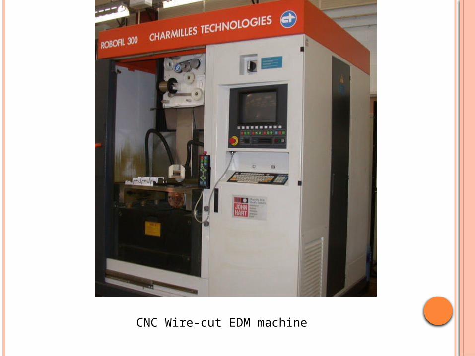
CNC Wire-cut EDM machine

REASEARCH AND DEVELOPMENT
AREAS
Name ofresearchers
Year Contribution
Workpiecematerial
Electrodematerial
Parameters taken into account
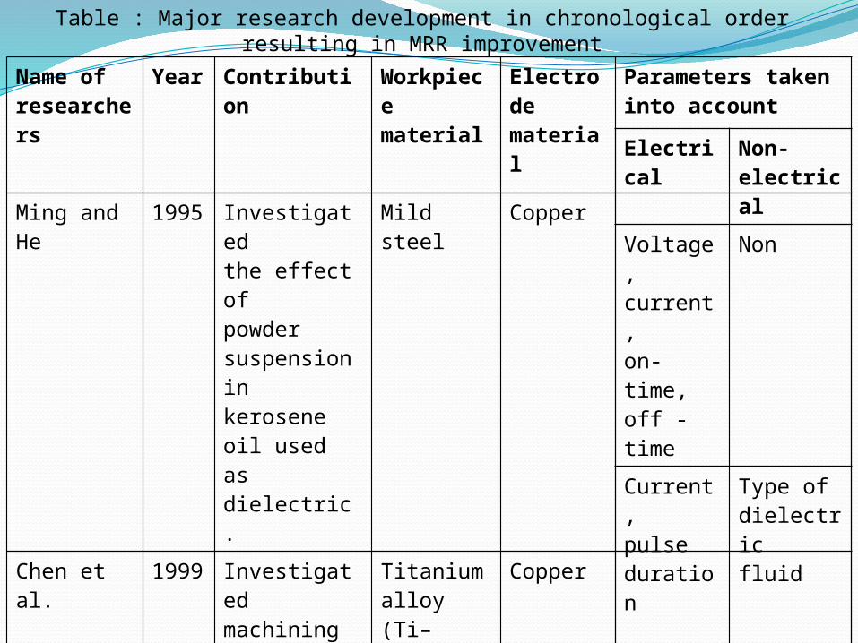
Ming and He
1995
Investigatedthe effect ofpowdersuspension inkerosene oil used asdielectric.
Mild steel Copper
Chen et al. 1999
Investigatedmachiningcharacteristicswith keroseneand distilledwater as thedielectrics.
Titaniumalloy (Ti–6A1–4V)
Copper
Electrical
Non-electrical
Voltage,current,on- time,off -time
Non
Current,pulseduration
Type ofdielectricfluid
Table : Major research development in chronological order resulting in MRR improvement

Name ofresearchers
Year Contribution
Workpiecematerial
Electrodematerial
Parameters taken into account
Aspinwall 2001
Investigatedhybrid highspeedmachiningprocess(EDM/HSM).
Steel Graphite
Mohan et al.
2004
Investigatedeffect of tubeelectroderotation onperformancemeasures.
6025 Al-alloyreinforcedwith SiCparticles
Brass
Electrical
Non-electrical
Voltage Electroderotation
Peakcurrent,polarity,pulseduration
Electroderotation,volumefraction ofSiCreinforcedParticles.
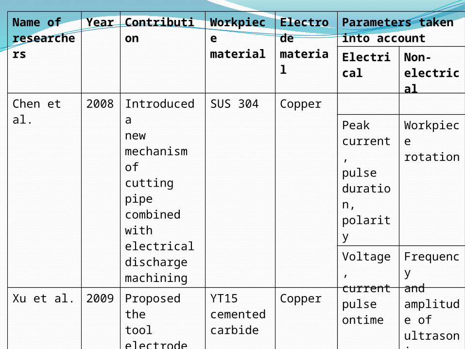
Name ofresearchers
Year Contribution
Workpiecematerial
Electrodematerial
Parameters taken into account
Chen et al. 2008
Introduced anewmechanism ofcutting pipecombined withelectricaldischargemachining
SUS 304 Copper
Xu et al. 2009
Proposed thetool electrodeultrasonicvibrationassisted EDMin gas mediumand introducedits principle.
YT15cementedcarbide
Copper
Electrical
Non-electrical
Peakcurrent,pulseduration,polarity
Workpiecerotation
Voltage,currentpulse ontime
Frequencyandamplitude ofultrasonicvibration,
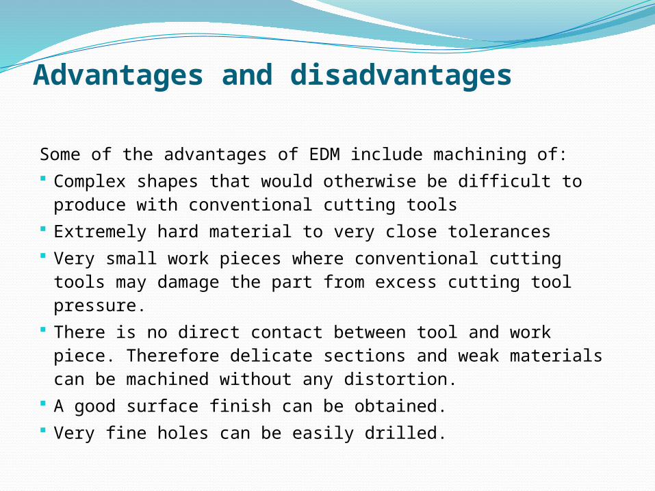
Advantages and disadvantages
Some of the advantages of EDM include machining of: Complex shapes that would otherwise be difficult to
produce with conventional cutting tools Extremely hard material to very close tolerances Very small work pieces where conventional cutting
tools may damage the part from excess cutting tool pressure.
There is no direct contact between tool and work piece. Therefore delicate sections and weak materials can be machined without any distortion.
A good surface finish can be obtained. Very fine holes can be easily drilled.
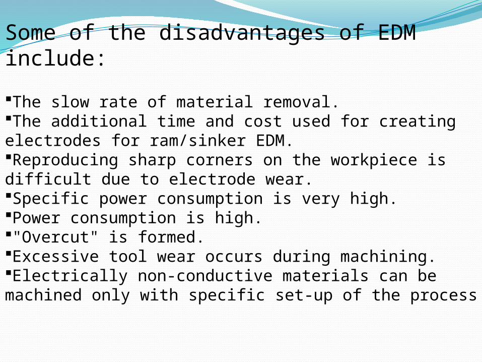
Some of the disadvantages of EDM include:
The slow rate of material removal. The additional time and cost used for creating electrodes for ram/sinker EDM. Reproducing sharp corners on the workpiece is difficult due to electrode wear. Specific power consumption is very high. Power consumption is high. "Overcut" is formed. Excessive tool wear occurs during machining. Electrically non-conductive materials can be machined only with specific set-up of the process
CONCLUSIONEDM has resulted out as most cost effective and precision machining process in recent years. The capacity of machining hard and difficult to machine parts has made EDM as one of the most important machining processes. The contribution Variants of EDM has brought tremendous improvements in the surface finish of machined advanced engineering materials. Powder mixed EDM and Ultrasonic assisted EDM has not only reduces tool wear but also increases material removal rate. Modeling and optimization of various electrical and non electrical parameters in EDM improved in precision machining of work materials The review of the research trends in EDM on rotary EDM, dry EDM machining, EDM with powder additives, Ultrasonic assisted EDM ,WEDM and Micro EDM performances is presented.


