EDR + AD Electronic Drilling Recorder with integrated Automatic Driller ABS-EDRAD-TINFO REV 0 An EDR system is nowadays included in all wellbore construction activities, required by law in majority of countries. In its basic form – real time data chart viewing and data storage – obtaining or implementing one in-house is straightforward. A major differentiator for this system is the optional but tightly integrated Automatic Driller function upgrade. Intended to enable computer assisted drilling. Simply described, the AD helps the driller ensure that the drill bit is pressed with the right force against the rock being drilled through. Maximum drilling efficiency hence is always maintained through any kind of formation. The add-on automatic driller delivers the fastest feedback-control given the direct mechanical link arrangement between the drawworks drum with the brake control motor. This results to smallest variations allowing creation of smoothest wellbore geometry. TECHNICAL INFORMATION Specifications Model Navigator Application Measurement and storage of real time drilling/workover rig parameters and machine assisted drilling via several mode settings Implementation EDR – sensor signals and calculated parameters are displayed real time and saved in computer database for historical views AD – electromechanical feedback control loop system interfaced with drawworls drum and brake handle Automatic Drilling Control Modes ΔP, WOB, WOB-MaxPumpPr, Time Drill, ROP Display Info Distribution Unlimited expandability of # of screens Viewable through Internet browser (eg via Satellite) Power Requirement 2 230 VAC ±10%, 8A max or 115 VAC ±10%, 15A max Operating Temperatures Display screen & control box: 0 to 55°C (32 to 131°F) Sensors (majority): -20 to 70°C (-4 to 158°F) Humidity Enclosures: 0 – 99% RH Ingress Protection Display Screen and Components Boxes: IP 66 Sensors (majority): IP 67 Weights Each individual component: < 50 lbs (22.7 kg) Approvals / Certification Sensors (majority): Intrinsically Safe ATEX EEx ia Driller Screen: Class I, Zone 2 (Div 2), ATEX/ IECEx Control Box: 10ATEX4123X, IECEx SIR 10.0061X Motor / Gearbox: UL/CSA Class I Div 1 Features • Rig floor, flow line and pits area sensors are standard and may be expanded or scaled down as needed. • WITS 1 In and Out capable to aggregate and to pass on to 3 rd party aggregators • Analog channels are available for integrating or aggregating any parameter at the work site (e.g., fuel levels, choke valve position). • EDR software includes on demand pipe tally, full daily drilling report, morning/evening brief reports, tour payroll and signature authentication, motor man’s report, survey, BHA and historical graphing • AD precise control in maintaining consistent energy transfer from the bit to the rock (i.e., Mechanical Specific Energy) achieving optimum ROP through any formation section. • Expect 15-20% improvement typical field-proven performance (above – without AD assist, below – with AD assist) • Drawworks movement is captured electromechanically and directly coupled to a gearbox system, resulting to instantaneous response as opposed to a few seconds delay with software-based control iterations. NOTES: 1 – Wellsite Information Transfer Specification, universal data exchange format for drilling related information 2 - Different VFD component depending on power voltage input
Transcript
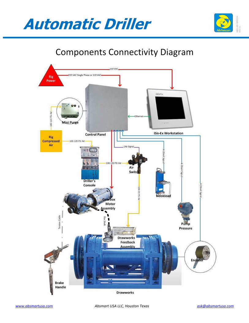
EDR + AD Electronic Drilling Recorder with integrated Automatic Driller
ABS-E
DRAD
-TIN
FO
REV 0
An EDR system is nowadays included in all
wellbore construction activities, required by law in majority of countries. In its basic form – real time data chart viewing and data storage – obtaining or implementing one in-house is straightforward.
A major differentiator for this system is the optional but tightly integrated Automatic Driller function upgrade. Intended to enable computer assisted drilling. Simply described, the AD helps the driller ensure that the drill bit is pressed with the right force against the rock being drilled through. Maximum drilling efficiency hence is always maintained through any kind of formation.
The add-on automatic driller delivers the fastest feedback-control given the direct mechanical
link arrangement between the drawworks drum with the brake control motor. This results to smallest variations allowing creation of smoothest wellbore geometry.
TE
CH
NI
CA
L
IN
FO
RM
AT
IO
N
Specifications
Model
Navigator
Application
Measurement and storage of real time
drilling/workover rig parameters and machine
assisted drilling via several mode settings
Implementation
EDR – sensor signals and calculated parameters are
displayed real time and saved in computer database
for historical views
AD – electromechanical feedback control loop system
interfaced with drawworls drum and brake handle
Automatic Drilling Control Modes
ΔP, WOB, WOB-MaxPumpPr, Time Drill, ROP
Display Info Distribution
Unlimited expandability of # of screens
Viewable through Internet browser (eg via Satellite)
Power Requirement2
230 VAC ±10%, 8A max or 115 VAC ±10%, 15A max
Operating Temperatures
Display screen & control box: 0 to 55°C (32 to 131°F)
Sensors (majority): -20 to 70°C (-4 to 158°F)
Humidity
Enclosures: 0 – 99% RH
Ingress Protection
Display Screen and Components Boxes: IP 66
Sensors (majority): IP 67
Weights
Each individual component: < 50 lbs (22.7 kg)
Approvals / Certification
Sensors (majority): Intrinsically Safe ATEX EEx ia
Driller Screen: Class I, Zone 2 (Div 2), ATEX/ IECEx
Control Box: 10ATEX4123X, IECEx SIR 10.0061X
Motor / Gearbox: UL/CSA Class I Div 1
Features
• Rig floor, flow line and pits area sensors are standard and may be expanded or scaled down as needed.
• WITS1 In and Out capable to aggregate and to pass on to 3rd party aggregators
• Analog channels are available for integrating or aggregating any parameter at the work site (e.g., fuel levels, choke valve position).
• EDR software includes on demand pipe tally, full daily drilling report, morning/evening brief reports, tour payroll and signature authentication, motor man’s report, survey, BHA and historical graphing
• AD precise control in maintaining consistent energy transfer from the bit to the rock (i.e., Mechanical Specific Energy) achieving optimum ROP through any formation section.
• Expect 15-20% improvement typical field-proven performance (above – without
AD assist, below – with AD assist)
• Drawworks movement is captured electromechanically and directly coupled to a gearbox system, resulting to instantaneous response
as opposed to a few seconds delay with software-based control iterations.
NOTES: 1 – Wellsite Information Transfer Specification, universal data exchange format for drilling related information
2 - Different VFD component depending on power voltage input
Improve Wellbore ConstructionDesigned as a universal add-on to drilling rigs outfitted with a brake handle, this system is the most aggressive automatic driller with numerous features to handle any type of drilling and guarantee the fastest penetration rates whilst protecting surface and downhole equipment, longer bit runs and measurable
economic benefits.
Controller Touch Screen System is specifically built for ease of use with a simple touch screen operating system.
The screen allows rapid control of the Automatic Driller with simple digital Weight-on-bit adjustments, pump pressure protection, differential pressure alarms, a ‘finesse’ control for controlled drilling situations and optional ROP and Time Drilling features.
System Components The system consists of a stainless IP66 Class 1 Div 2 (Zone 2 equivalent) control box mounted in the dog house connected to a high power motor and gear box assembly on the drawworks allowing both aggressive and controlled drilling to maximize for ROP and give smooth in-gauge hole and improved downhole bit, motor and MWD life, and reduced BHA and drill string, vibration and wear. With 14+ yrs and >100 units in the field, system holds numerous records for highest average ROP and bit runs in West Texas.
Custom Drilling Controls The automatic driller has enhanced versatility with three different custom drilling modes in addition to just weight on bit to cover any type of drilling scenario.
Features Weight on Bit drilling Weight and maximum pump pressure drilling Differential pressure with maximum weight on bit Driller Speed percentage for “sweet spot” drilling Rate of Penetration Drilling Time Drilling Compact rugged design Simple to use Easy set-up and calibration Multiple drilling modes Low maintenance Modular design
Benefits Improved penetration rates Extended Bit/BHA life, Time and money savings due to drill time savings, faster operation and multiple drilling modes.
The automatic driller has multiple drilling modes and features to optimize for any type of drilling operation with maximum control.
Drilling Differential Pressure
The system has an aggressive differential drilling feature that will keep the pump pressure variation caused by mud motors and PDC bits in as tight a bandwidth as the directional driller requires for the type of drilling. Ideal for steering, tool face corrections, sliding or maximizing motor and life. Eliminates bit skid, bit whirl and motor stalls.
Driller Percentage speed–Weight on bit and Differential drilling
The Driller percentage speed feature allows the driller to reduce energy being supplied to the lift line on the brake handle. This reduces aggressiveness of the
system and allows the “sweet spot” to be achieved where the drill bit is continuously moving forward all the time. Ideal for interbedded formations with varying compressive strengths.
Pump pressure protection-WOB drilling When drilling to maximize for rate of penetration and not wanting to stall a motor or cause bit stick-slip, the driller can set the desired weight on bit and the maximum desired pump pressure. When the maximum pressure is reached the system will reduce the weight until the pressure goes below the desired level.
Time Drill and ROP Drill Through the drawworks encoder high-resolution counts data, it can drill with a fixed required ROP or release the drilling line at pre-determined intervals. With ROP drilling the system uses three measurements the maximum weight on bit, the minimum weight on bit and desired ROP to continually alter weight to give and maintain drilling speed in controlled drilling scenarios such as LWD logging, coring, approaching reservoirs etc. With the Time Drill feature, the operator just sets the amount of line travel and the number repetitions required. The perfect tool for drilling off cement plugs, whipstocks, coring, or fishing and milling operations.