Student Notes: CATIA V5 Fundamentals- Lesson 3: Basic Features Copyright DASSAULT SYSTEMES 3-1 Copyright DASSAULT SYSTEMES Case Study: Basic Features Design Intent Stages in the Process Determine a Suitable Base Feature Create Pad and Pocket Features Create Holes Create Fillets and Chamfers Basic Features In this lesson you will learn how to create basic CATIA features. Duration: Approximately 0.33 day Lesson Contents:
Transcript
Student Notes:
CATIA V5 Fundamentals- Lesson 3: Basic Features ������������
Copyright DASSAULT SYSTEMES 3-1
Cop
yrig
ht D
AS
SA
ULT
SY
STE
ME
S
Case Study: Basic FeaturesDesign IntentStages in the ProcessDetermine a Suitable Base FeatureCreate Pad and Pocket FeaturesCreate HolesCreate Fillets and Chamfers
Basic Features
In this lesson you will learn how to create basic CATIA features.
Duration: Approximately 0.33 day
Lesson Contents:
Student Notes:
CATIA V5 Fundamentals- Lesson 3: Basic Features ������������
Copyright DASSAULT SYSTEMES 3-2
Cop
yrig
ht D
AS
SA
ULT
SY
STE
ME
S
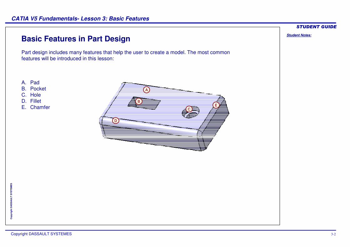
Basic Features in Part Design
A
B
C
D
E
Part design includes many features that help the user to create a model. The most common features will be introduced in this lesson:
A. PadB. PocketC. HoleD. Fillet E. Chamfer
Student Notes:
CATIA V5 Fundamentals- Lesson 3: Basic Features ������������
Copyright DASSAULT SYSTEMES 3-3
Cop
yrig
ht D
AS
SA
ULT
SY
STE
ME
S
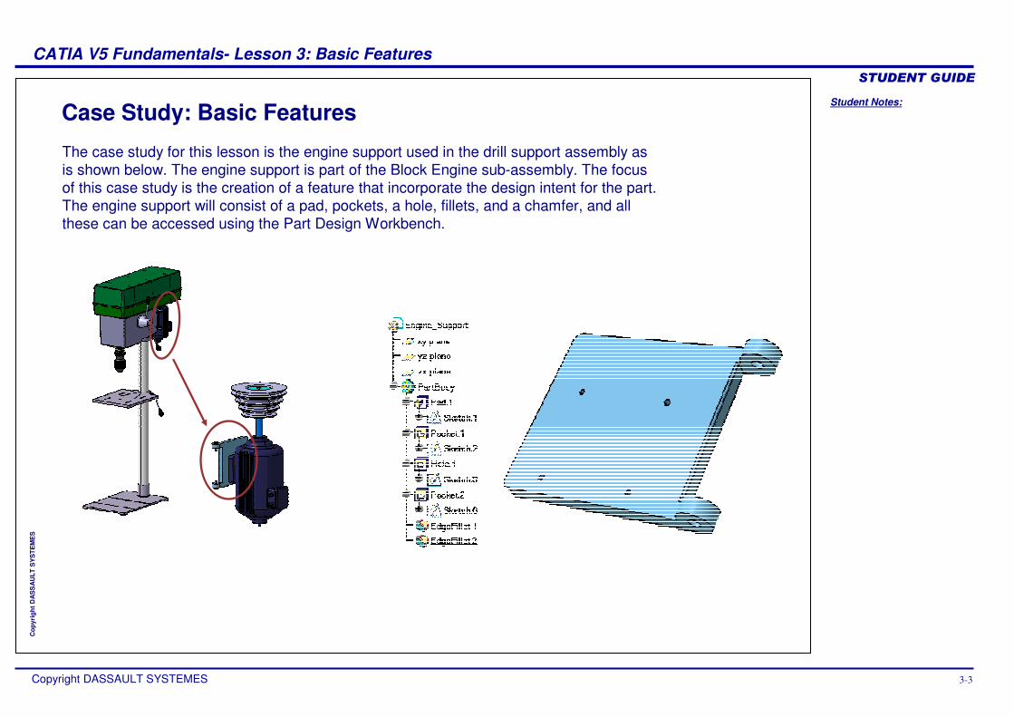
Case Study: Basic Features
The case study for this lesson is the engine support used in the drill support assembly as is shown below. The engine support is part of the Block Engine sub-assembly. The focus of this case study is the creation of a feature that incorporate the design intent for the part. The engine support will consist of a pad, pockets, a hole, fillets, and a chamfer, and all these can be accessed using the Part Design Workbench.
Student Notes:
CATIA V5 Fundamentals- Lesson 3: Basic Features ������������
Copyright DASSAULT SYSTEMES 3-4
Cop
yrig
ht D
AS
SA
ULT
SY
STE
ME
S
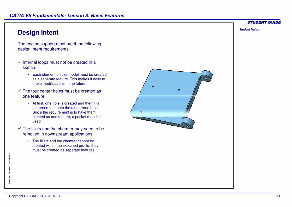
Design Intent
The engine support must meet the following design intent requirements:
� Internal loops must not be created in a sketch.
• Each element on this model must be created as a separate feature. This makes it easy to make modifications in the future.
� The four center holes must be created as one feature.
• At first, one hole is created and then it is patterned to create the other three holes. Since the requirement is to have them created as one feature, a pocket must be used.
� The fillets and the chamfer may need to be removed in downstream applications.
• The fillets and the chamfer cannot be created within the sketched profile; they must be created as separate features
Student Notes:
CATIA V5 Fundamentals- Lesson 3: Basic Features ������������
Copyright DASSAULT SYSTEMES 3-5
Cop
yrig
ht D
AS
SA
ULT
SY
STE
ME
S
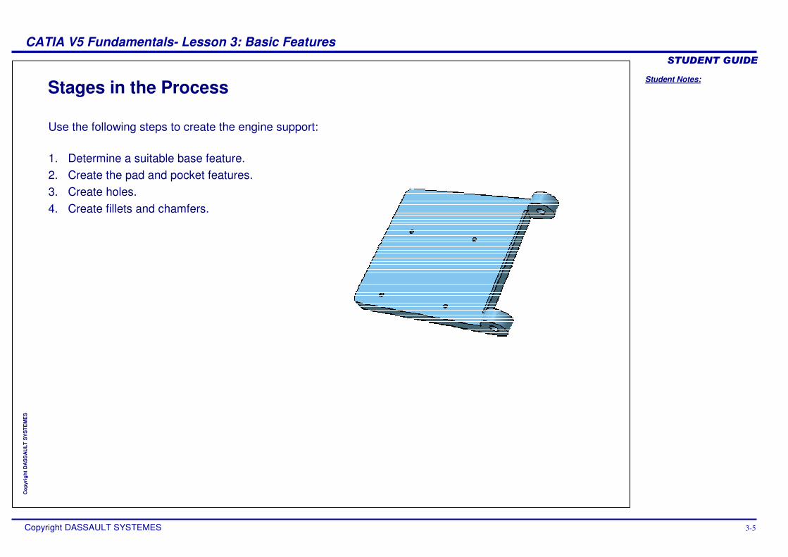
Stages in the Process
Use the following steps to create the engine support:
1. Determine a suitable base feature. 2. Create the pad and pocket features.3. Create holes.4. Create fillets and chamfers.
Student Notes:
CATIA V5 Fundamentals- Lesson 3: Basic Features ������������
Copyright DASSAULT SYSTEMES 3-6
Cop
yrig
ht D
AS
SA
ULT
SY
STE
ME
S
Determine a Suitable Base FeatureIn this section you will learn how to create the base feature in a model.
Use the following steps:
1. Determine a suitable base feature.
2. Create pad and pocket features.3. Create holes.4. Create fillets and chamfers.
Student Notes:
CATIA V5 Fundamentals- Lesson 3: Basic Features ������������
Copyright DASSAULT SYSTEMES 3-7
Cop
yrig
ht D
AS
SA
ULT
SY
STE
ME
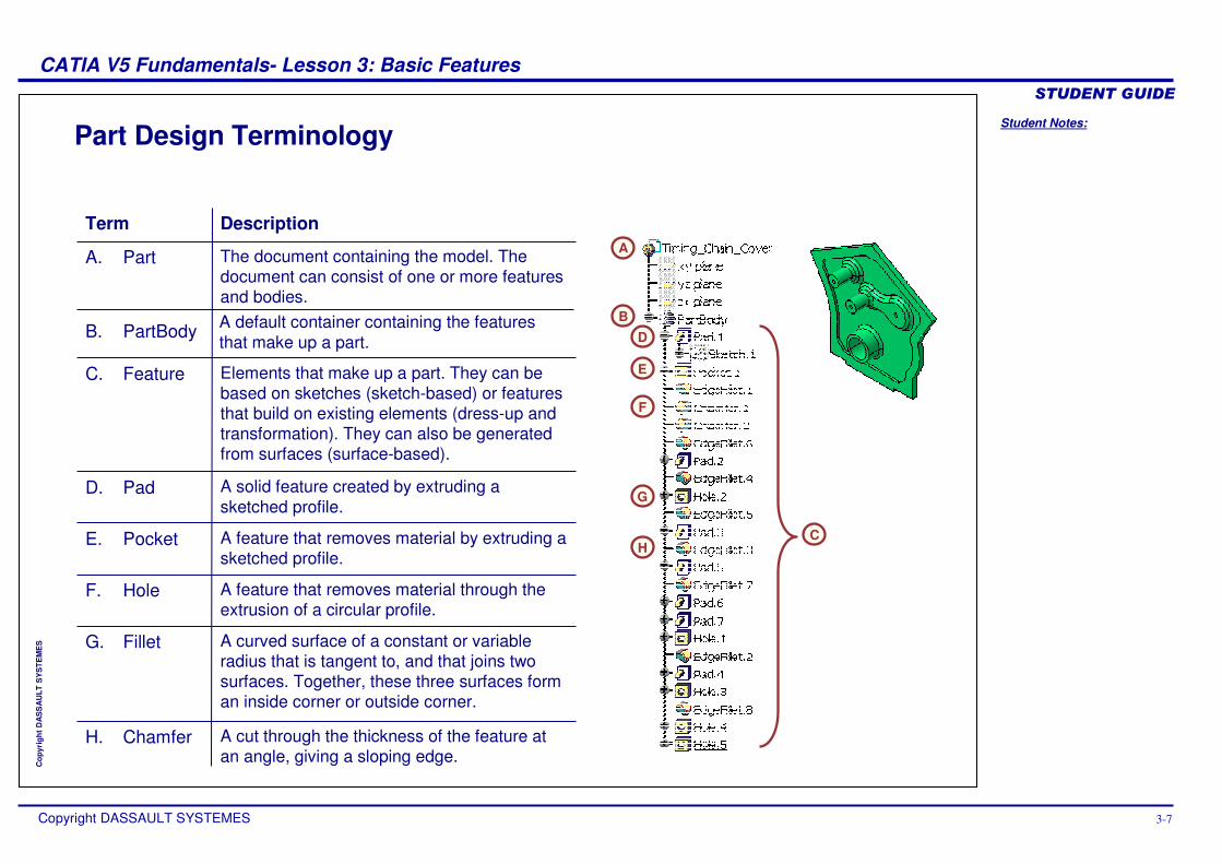
S A curved surface of a constant or variable radius that is tangent to, and that joins two surfaces. Together, these three surfaces form an inside corner or outside corner.
A feature that removes material through the extrusion of a circular profile.
A feature that removes material by extruding a sketched profile.
Part Design Terminology
A
C
D
E
G
H
F
Term
PartA.
FeatureC.
The document containing the model. The document can consist of one or more features and bodies.
Elements that make up a part. They can be based on sketches (sketch-based) or features that build on existing elements (dress-up and transformation). They can also be generated from surfaces (surface-based).
A solid feature created by extruding a sketched profile.
A cut through the thickness of the feature at an angle, giving a sloping edge.
Description
D.
E.
F.
G.
H. Chamfer
Fillet
Hole
Pocket
Pad
PartBodyB. A default container containing the features that make up a part.
B
Student Notes:
CATIA V5 Fundamentals- Lesson 3: Basic Features ������������
Copyright DASSAULT SYSTEMES 3-8
Cop
yrig
ht D
AS
SA
ULT
SY
STE
ME
S
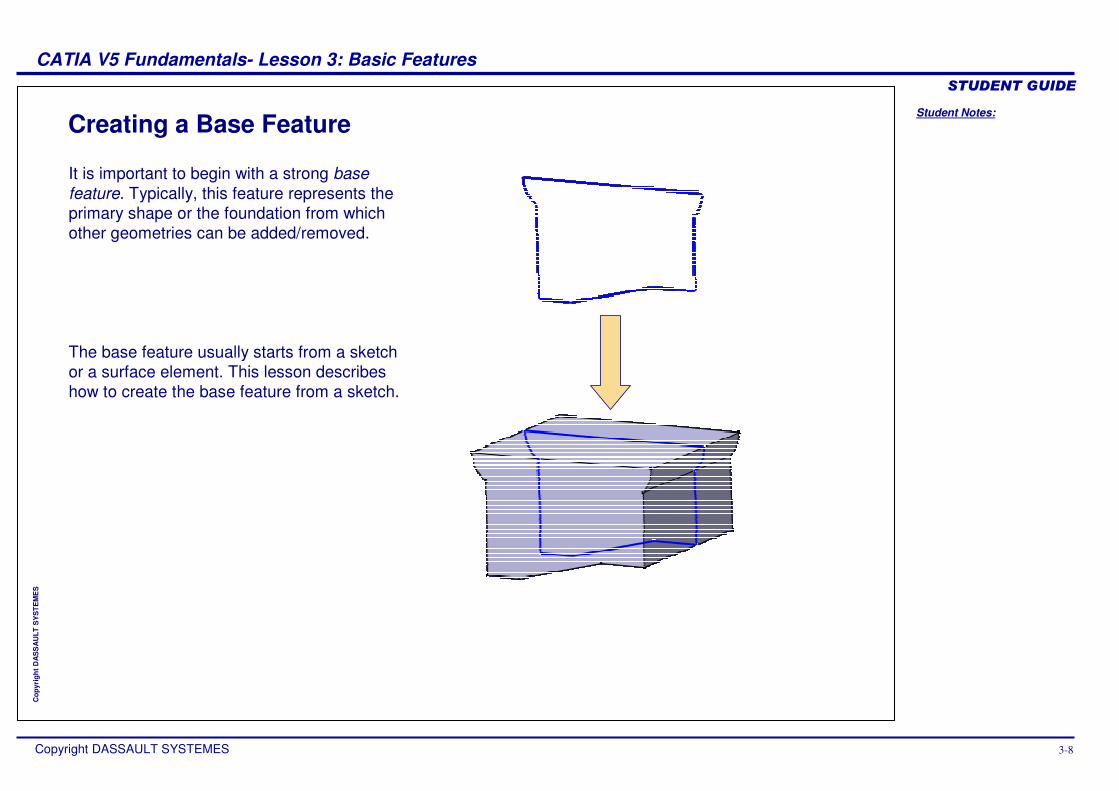
Creating a Base Feature
It is important to begin with a strong base feature. Typically, this feature represents the primary shape or the foundation from which other geometries can be added/removed.
The base feature usually starts from a sketch or a surface element. This lesson describes how to create the base feature from a sketch.
Student Notes:
CATIA V5 Fundamentals- Lesson 3: Basic Features ������������
Copyright DASSAULT SYSTEMES 3-9
Cop
yrig
ht D
AS
SA
ULT
SY
STE
ME
S
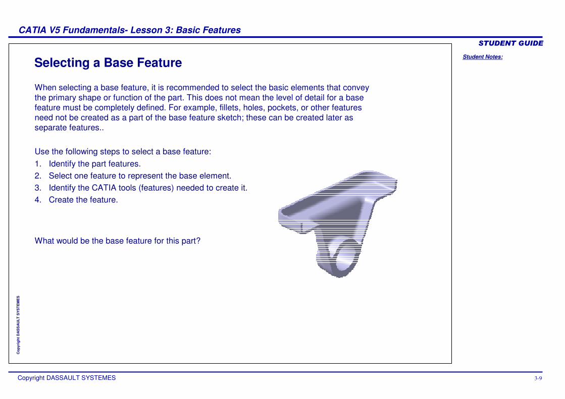
Selecting a Base Feature
When selecting a base feature, it is recommended to select the basic elements that convey the primary shape or function of the part. This does not mean the level of detail for a base feature must be completely defined. For example, fillets, holes, pockets, or other features need not be created as a part of the base feature sketch; these can be created later as separate features..
Use the following steps to select a base feature:1. Identify the part features.2. Select one feature to represent the base element.3. Identify the CATIA tools (features) needed to create it.4. Create the feature.
What would be the base feature for this part?
Student Notes:
CATIA V5 Fundamentals- Lesson 3: Basic Features ������������
Copyright DASSAULT SYSTEMES 3-10
Cop
yrig
ht D
AS
SA
ULT
SY
STE
ME
S
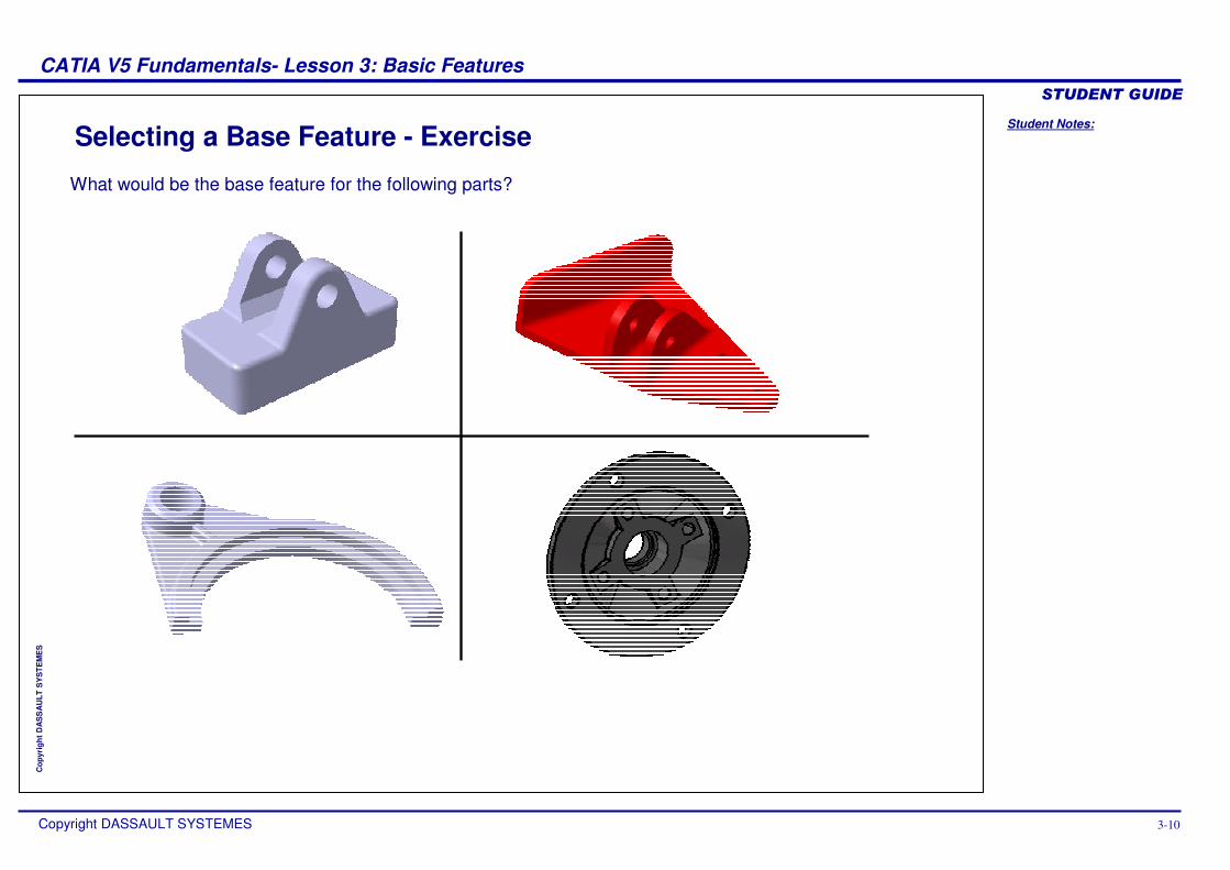
Selecting a Base Feature - Exercise
What would be the base feature for the following parts?
Student Notes:
CATIA V5 Fundamentals- Lesson 3: Basic Features ������������
Copyright DASSAULT SYSTEMES 3-11
Cop
yrig
ht D
AS
SA
ULT
SY
STE
ME
S
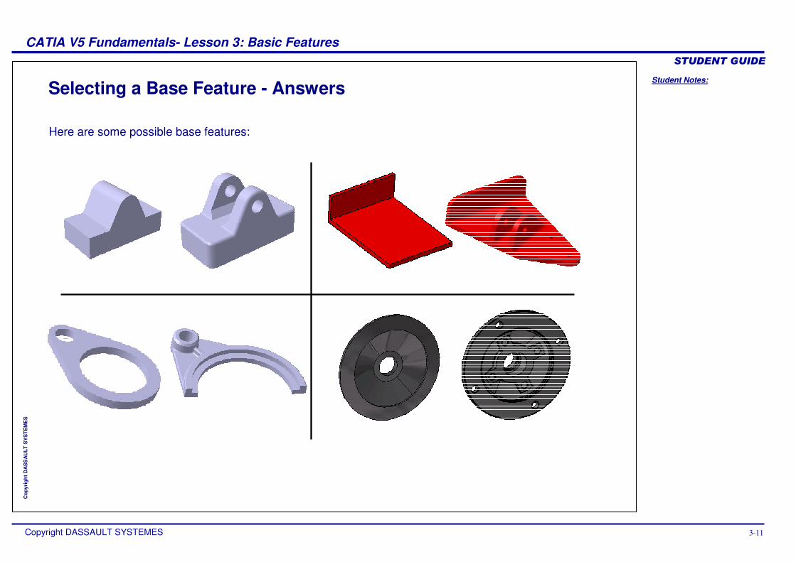
Selecting a Base Feature - Answers
Here are some possible base features:
Student Notes:
CATIA V5 Fundamentals- Lesson 3: Basic Features ������������
Copyright DASSAULT SYSTEMES 3-12
Cop
yrig
ht D
AS
SA
ULT
SY
STE
ME
S
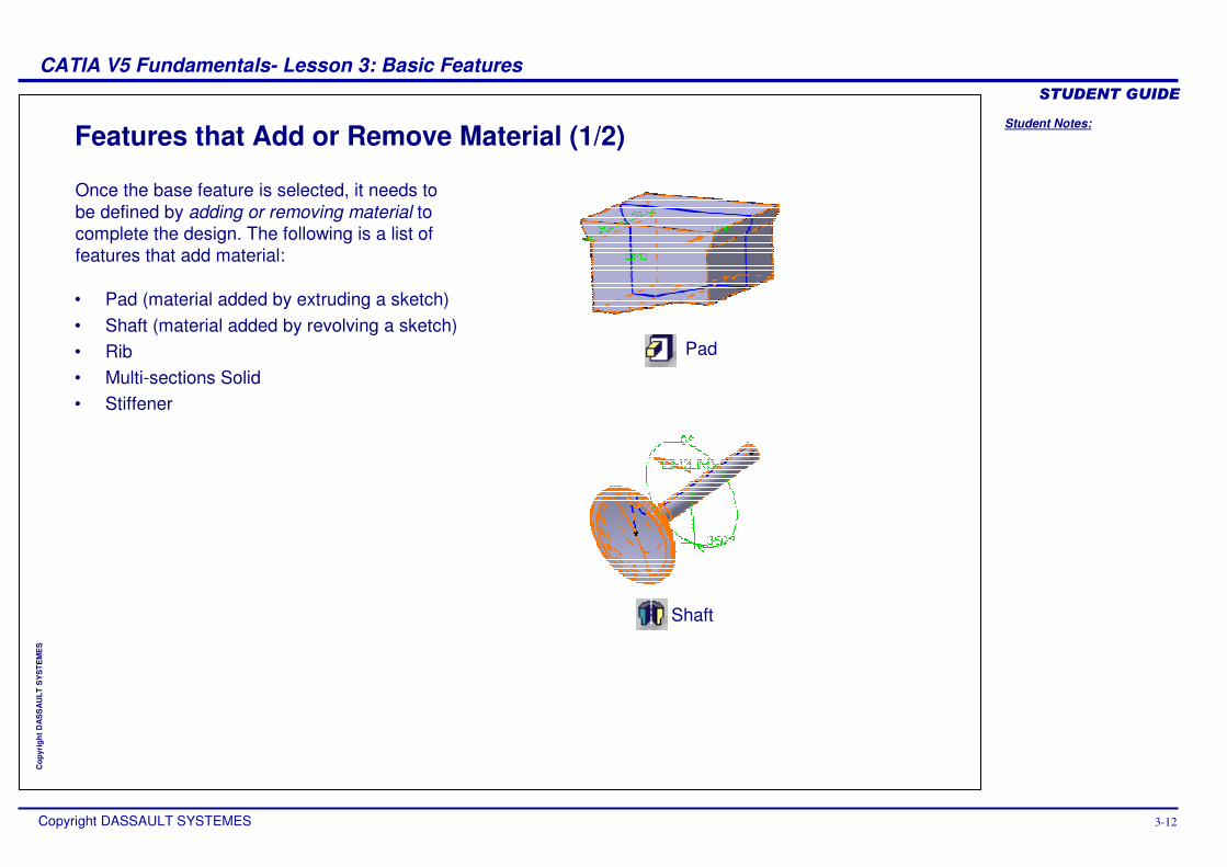
• Pad (material added by extruding a sketch) • Shaft (material added by revolving a sketch) • Rib • Multi-sections Solid • Stiffener
Features that Add or Remove Material (1/2)
Pad
Shaft
Once the base feature is selected, it needs to be defined by adding or removing material to complete the design. The following is a list of features that add material:
Student Notes:
CATIA V5 Fundamentals- Lesson 3: Basic Features ������������
Copyright DASSAULT SYSTEMES 3-13
Cop
yrig
ht D
AS
SA
ULT
SY
STE
ME
S
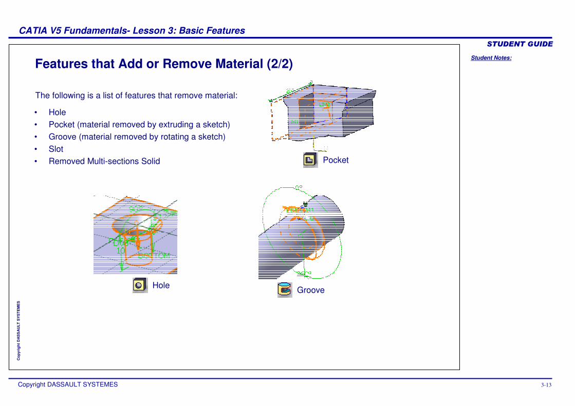
Features that Add or Remove Material (2/2)
• Hole• Pocket (material removed by extruding a sketch)• Groove (material removed by rotating a sketch)• Slot• Removed Multi-sections Solid Pocket
GrooveHole
The following is a list of features that remove material:
Student Notes:
CATIA V5 Fundamentals- Lesson 3: Basic Features ������������
Copyright DASSAULT SYSTEMES 3-14
Cop
yrig
ht D
AS
SA
ULT
SY
STE
ME
S
Create Pad and Pocket FeaturesIn this section, you will learn how to create simple pads and pockets from a 2D profile (or sketch).
Use the following steps:
1. Determine a suitable base feature.
2. Create pad and pocket features.
3. Create holes.4. Create fillets and chamfers.
Student Notes:
CATIA V5 Fundamentals- Lesson 3: Basic Features ������������
Copyright DASSAULT SYSTEMES 3-15
Cop
yrig
ht D
AS
SA
ULT
SY
STE
ME
S
Creating Pads1
2
5
3
4
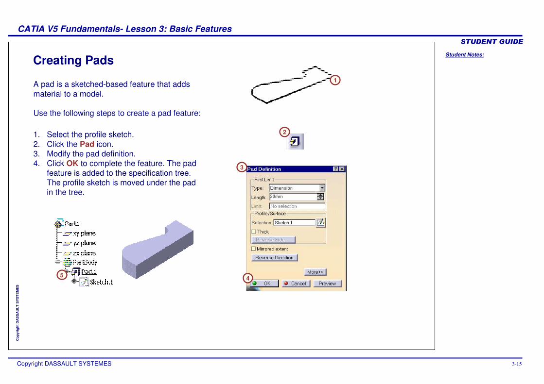
A pad is a sketched-based feature that adds material to a model.
Use the following steps to create a pad feature:
1. Select the profile sketch.2. Click the Pad icon.3. Modify the pad definition.4. Click OK to complete the feature. The pad
feature is added to the specification tree. The profile sketch is moved under the pad in the tree.
Student Notes:
CATIA V5 Fundamentals- Lesson 3: Basic Features ������������
Copyright DASSAULT SYSTEMES 3-16
Cop
yrig
ht D
AS
SA
ULT
SY
STE
ME
S
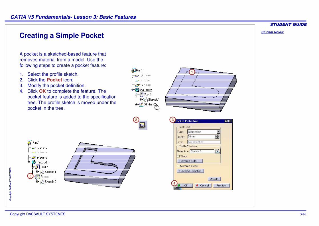
Creating a Simple Pocket
1
2 3
4
5
A pocket is a sketched-based feature that removes material from a model. Use the following steps to create a pocket feature:
1. Select the profile sketch.2. Click the Pocket icon.3. Modify the pocket definition.4. Click OK to complete the feature. The
pocket feature is added to the specification tree. The profile sketch is moved under the pocket in the tree.
Student Notes:
CATIA V5 Fundamentals- Lesson 3: Basic Features ������������
Copyright DASSAULT SYSTEMES 3-17
Cop
yrig
ht D
AS
SA
ULT
SY
STE
ME
S
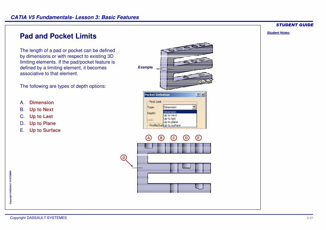
Pad and Pocket Limits
Example
A B C D E
The length of a pad or pocket can be defined by dimensions or with respect to existing 3D limiting elements. If the pad/pocket feature is defined by a limiting element, it becomes associative to that element.
The following are types of depth options:
A. DimensionB. Up to NextC. Up to LastD. Up to PlaneE. Up to Surface
D
Student Notes:
CATIA V5 Fundamentals- Lesson 3: Basic Features ������������
Copyright DASSAULT SYSTEMES 3-18
Cop
yrig
ht D
AS
SA
ULT
SY
STE
ME
S
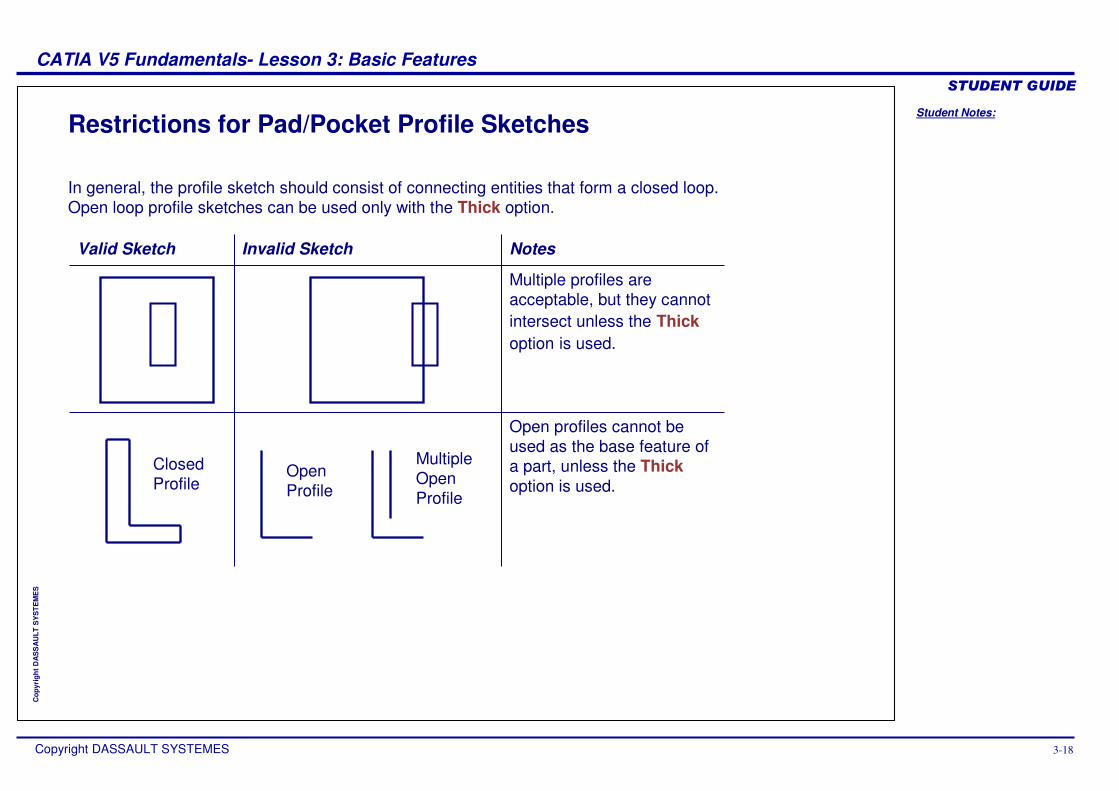
Restrictions for Pad/Pocket Profile Sketches
Closed Profile
Open Profile
Multiple Open Profile
In general, the profile sketch should consist of connecting entities that form a closed loop. Open loop profile sketches can be used only with the Thick option.
Valid Sketch Invalid Sketch Notes
Multiple profiles are acceptable, but they cannot intersect unless the Thick option is used.
Open profiles cannot be used as the base feature of a part, unless the Thickoption is used.
Student Notes:
CATIA V5 Fundamentals- Lesson 3: Basic Features ������������
Copyright DASSAULT SYSTEMES 3-19
Cop
yrig
ht D
AS
SA
ULT
SY
STE
ME
S
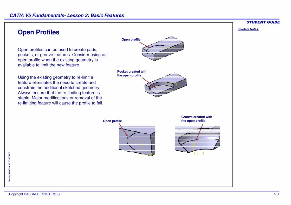
Open ProfilesOpen profile
Pocket created with the open profile
Open profileGroove created with the open profile
Open profiles can be used to create pads, pockets, or groove features. Consider using an open profile when the existing geometry is available to limit the new feature.
Using the existing geometry to re-limit a feature eliminates the need to create and constrain the additional sketched geometry. Always ensure that the re-limiting feature is stable. Major modifications or removal of the re-limiting feature will cause the profile to fail.
Student Notes:
CATIA V5 Fundamentals- Lesson 3: Basic Features ������������
Copyright DASSAULT SYSTEMES 3-20
Cop
yrig
ht D
AS
SA
ULT
SY
STE
ME
S
Create HolesIn this section, you will learn how to create different types of holes and locate them on existing features.
Use the following steps:
1. Determine a suitable base feature.
2. Create pad and pocket features.3. Create holes.4. Create fillets and chamfers.
Student Notes:
CATIA V5 Fundamentals- Lesson 3: Basic Features ������������
Copyright DASSAULT SYSTEMES 3-21
Cop
yrig
ht D
AS
SA
ULT
SY
STE
ME
S
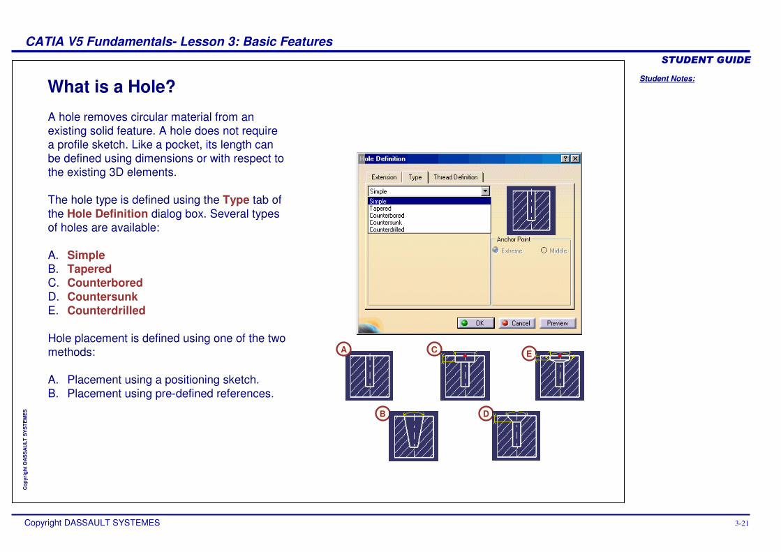
What is a Hole?
A
B
C
D
E
A hole removes circular material from an existing solid feature. A hole does not require a profile sketch. Like a pocket, its length can be defined using dimensions or with respect to the existing 3D elements.
The hole type is defined using the Type tab of the Hole Definition dialog box. Several types of holes are available:
A. SimpleB. TaperedC. CounterboredD. CountersunkE. Counterdrilled
Hole placement is defined using one of the two methods:
A. Placement using a positioning sketch.B. Placement using pre-defined references.
Student Notes:
CATIA V5 Fundamentals- Lesson 3: Basic Features ������������
Copyright DASSAULT SYSTEMES 3-22
Cop
yrig
ht D
AS
SA
ULT
SY
STE
ME
S
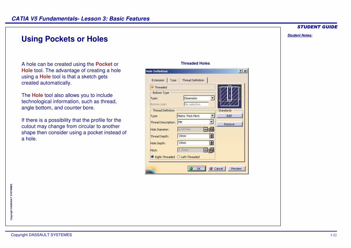
Using Pockets or Holes
A hole can be created using the Pocket or Hole tool. The advantage of creating a hole using a Hole tool is that a sketch getscreated automatically.
The Hole tool also allows you to include technological information, such as thread, angle bottom, and counter bore.
If there is a possibility that the profile for the cutout may change from circular to another shape then consider using a pocket instead of a hole.
Threaded Holes
Student Notes:
CATIA V5 Fundamentals- Lesson 3: Basic Features ������������
Copyright DASSAULT SYSTEMES 3-23
Cop
yrig
ht D
AS
SA
ULT
SY
STE
ME
S
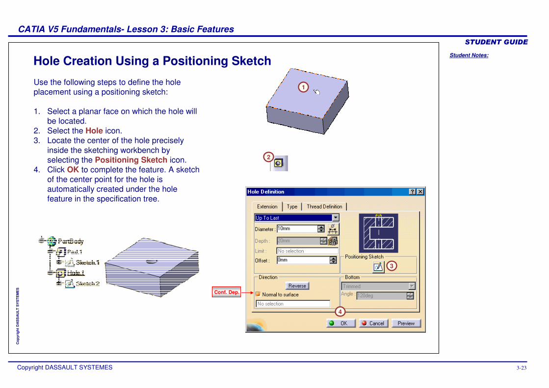
Hole Creation Using a Positioning Sketch
1
2
3
4
Use the following steps to define the hole placement using a positioning sketch:
1. Select a planar face on which the hole will be located.
2. Select the Hole icon.3. Locate the center of the hole precisely
inside the sketching workbench by selecting the Positioning Sketch icon.
4. Click OK to complete the feature. A sketch of the center point for the hole is automatically created under the hole feature in the specification tree.
Conf. Dep.
Student Notes:
CATIA V5 Fundamentals- Lesson 3: Basic Features ������������
Copyright DASSAULT SYSTEMES 3-24
Cop
yrig
ht D
AS
SA
ULT
SY
STE
ME
S
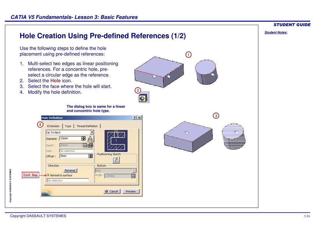
Hole Creation Using Pre-defined References (1/2)
2
4
1
3
The dialog box is same for a linear and concentric hole type.
Use the following steps to define the hole placement using pre-defined references:
1. Multi-select two edges as linear positioning references. For a concentric hole, pre-select a circular edge as the reference.
2. Select the Hole icon.3. Select the face where the hole will start.4. Modify the hole definition.
Conf. Dep.
Student Notes:
CATIA V5 Fundamentals- Lesson 3: Basic Features ������������
Copyright DASSAULT SYSTEMES 3-25
Cop
yrig
ht D
AS
SA
ULT
SY
STE
ME
S
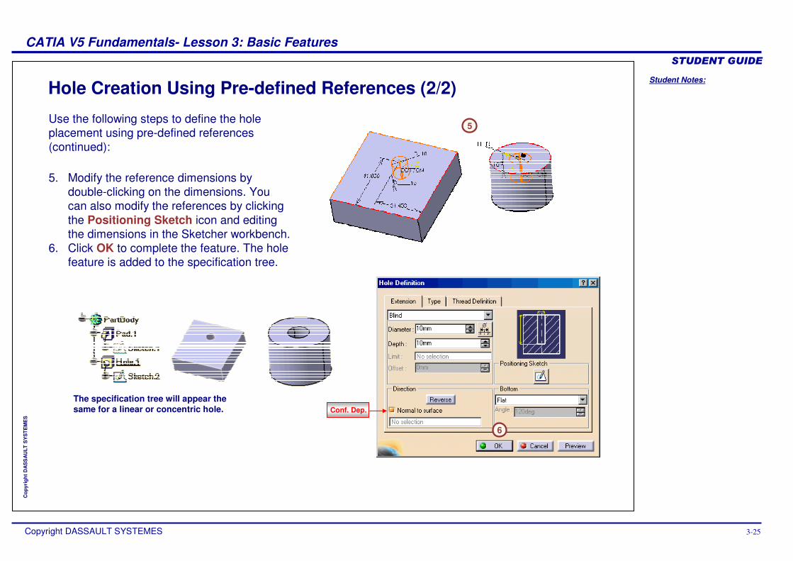
Hole Creation Using Pre-defined References (2/2)
5
The specification tree will appear the same for a linear or concentric hole.
6
Use the following steps to define the hole placement using pre-defined references (continued):
5. Modify the reference dimensions by double-clicking on the dimensions. You can also modify the references by clicking the Positioning Sketch icon and editing the dimensions in the Sketcher workbench.
6. Click OK to complete the feature. The hole feature is added to the specification tree.
Conf. Dep.
Student Notes:
CATIA V5 Fundamentals- Lesson 3: Basic Features ������������
Copyright DASSAULT SYSTEMES 3-26
Cop
yrig
ht D
AS
SA
ULT
SY
STE
ME
S
Create Fillets and ChamfersIn this section, you will learn how to create fillets and chamfers.
Use the following steps:
1. Determine a suitable base feature.
2. Create pad and pocket features.3. Create holes.4. Create fillets and
chamfers.
Student Notes:
CATIA V5 Fundamentals- Lesson 3: Basic Features ������������
Copyright DASSAULT SYSTEMES 3-27
Cop
yrig
ht D
AS
SA
ULT
SY
STE
ME
S
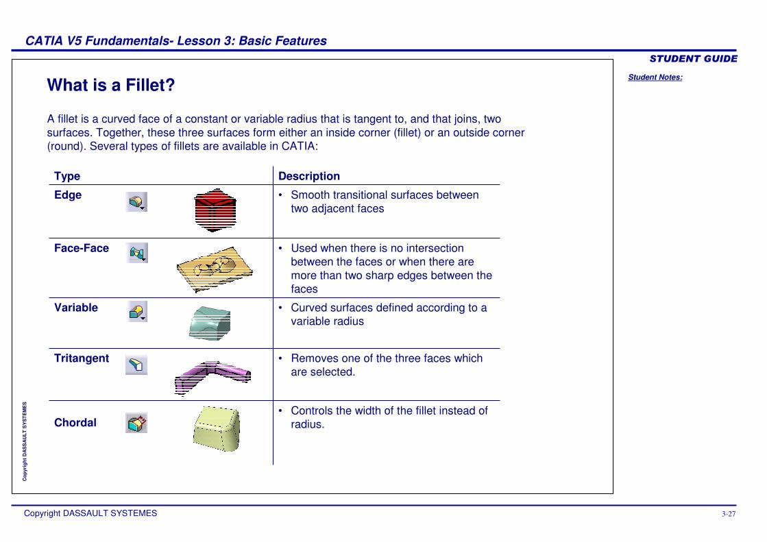
What is a Fillet?
Description
• Smooth transitional surfaces between two adjacent faces
• Used when there is no intersection between the faces or when there are more than two sharp edges between the faces
• Curved surfaces defined according to a variable radius
• Removes one of the three faces which are selected.
Tritangent
Variable
Face-Face
Edge
A fillet is a curved face of a constant or variable radius that is tangent to, and that joins, two surfaces. Together, these three surfaces form either an inside corner (fillet) or an outside corner (round). Several types of fillets are available in CATIA:
Type
• Controls the width of the fillet instead of radius.Chordal
Student Notes:
CATIA V5 Fundamentals- Lesson 3: Basic Features ������������
Copyright DASSAULT SYSTEMES 3-28
Cop
yrig
ht D
AS
SA
ULT
SY
STE
ME
S
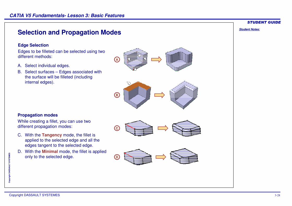
Selection and Propagation Modes
B
A
C
D
Edge SelectionEdges to be filleted can be selected using two different methods:
A. Select individual edges.B. Select surfaces – Edges associated with
the surface will be filleted (including internal edges).
Propagation modesWhile creating a fillet, you can use two different propagation modes:
C. With the Tangency mode, the fillet is applied to the selected edge and all the edges tangent to the selected edge.
D. With the Minimal mode, the fillet is applied only to the selected edge.
Student Notes:
CATIA V5 Fundamentals- Lesson 3: Basic Features ������������
Copyright DASSAULT SYSTEMES 3-29
Cop
yrig
ht D
AS
SA
ULT
SY
STE
ME
S
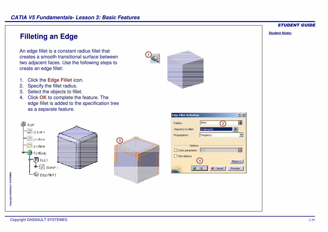
Filleting an Edge
1
3
2
4
An edge fillet is a constant radius fillet that creates a smooth transitional surface between two adjacent faces. Use the following steps to create an edge fillet:
1. Click the Edge Fillet icon.2. Specify the fillet radius.3. Select the objects to fillet.4. Click OK to complete the feature. The
edge fillet is added to the specification tree as a separate feature.
Student Notes:
CATIA V5 Fundamentals- Lesson 3: Basic Features ������������
Copyright DASSAULT SYSTEMES 3-30
Cop
yrig
ht D
AS
SA
ULT
SY
STE
ME
S
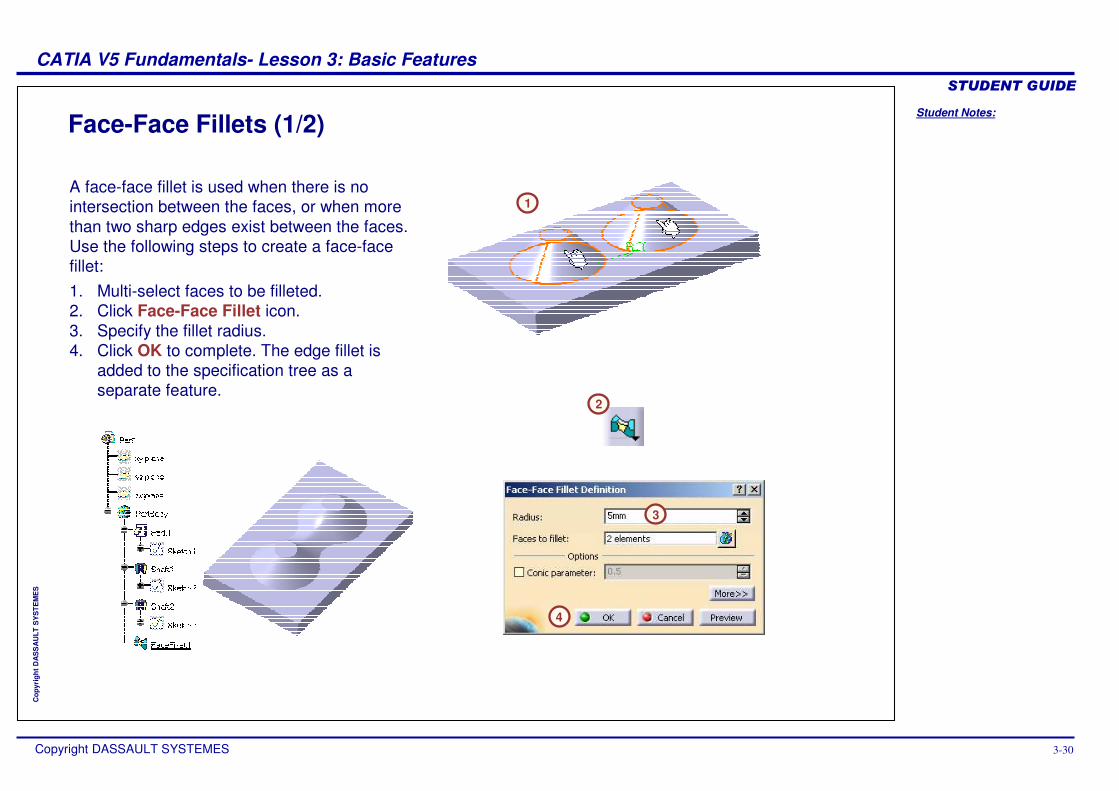
Face-Face Fillets (1/2)
2
3
4
1A face-face fillet is used when there is no intersection between the faces, or when more than two sharp edges exist between the faces. Use the following steps to create a face-face fillet:1. Multi-select faces to be filleted.2. Click Face-Face Fillet icon.3. Specify the fillet radius.4. Click OK to complete. The edge fillet is
added to the specification tree as a separate feature.
Student Notes:
CATIA V5 Fundamentals- Lesson 3: Basic Features ������������
Copyright DASSAULT SYSTEMES 3-31
Cop
yrig
ht D
AS
SA
ULT
SY
STE
ME
S
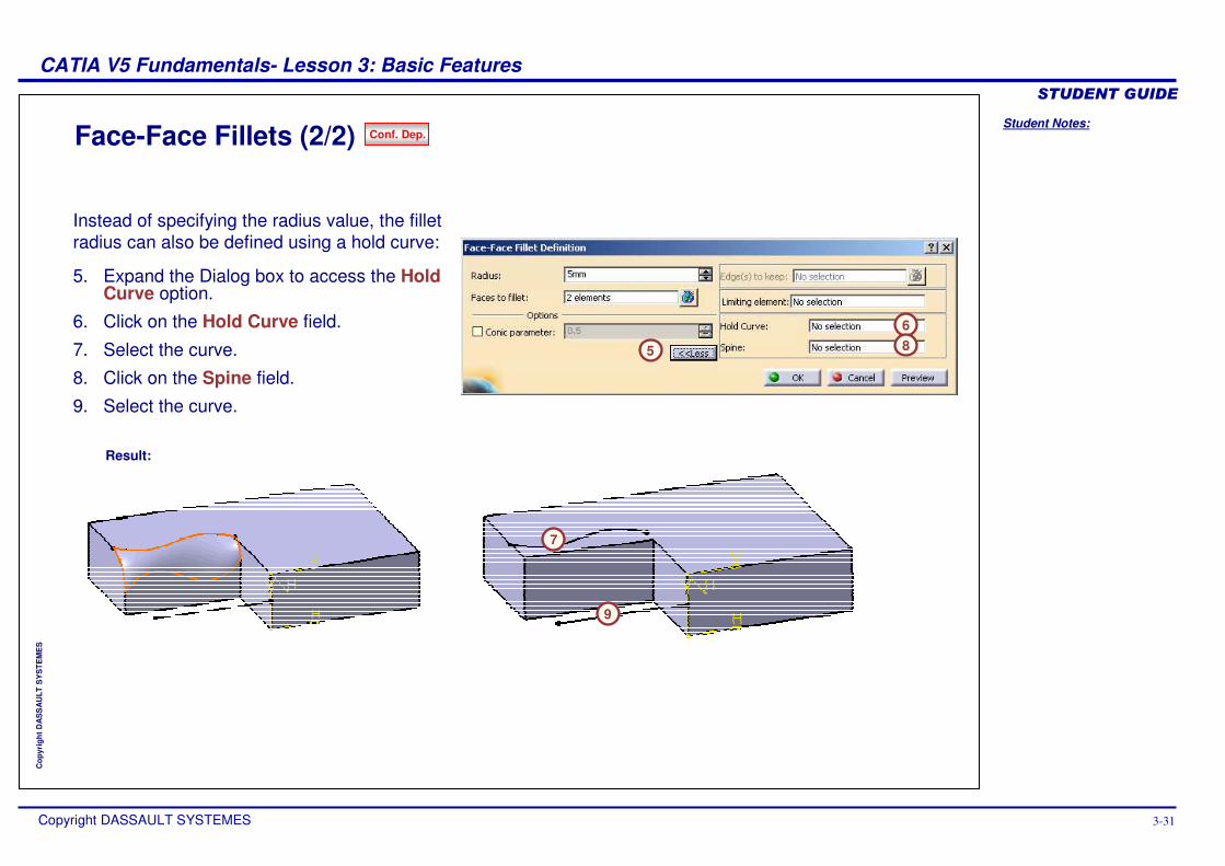
Face-Face Fillets (2/2)
Result:
5
68
7
9
Instead of specifying the radius value, the fillet radius can also be defined using a hold curve:
5. Expand the Dialog box to access the Hold Curve option.
6. Click on the Hold Curve field.
7. Select the curve.
8. Click on the Spine field.
9. Select the curve.
Conf. Dep.
Student Notes:
CATIA V5 Fundamentals- Lesson 3: Basic Features ������������
Copyright DASSAULT SYSTEMES 3-32
Cop
yrig
ht D
AS
SA
ULT
SY
STE
ME
S
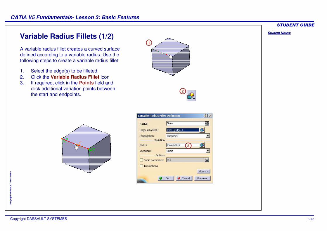
Variable Radius Fillets (1/2)
2
1
3
A variable radius fillet creates a curved surface defined according to a variable radius. Use the following steps to create a variable radius fillet:
1. Select the edge(s) to be filleted.2. Click the Variable Radius Fillet icon3. If required, click in the Points field and
click additional variation points between the start and endpoints.
Student Notes:
CATIA V5 Fundamentals- Lesson 3: Basic Features ������������
Copyright DASSAULT SYSTEMES 3-33
Cop
yrig
ht D
AS
SA
ULT
SY
STE
ME
S
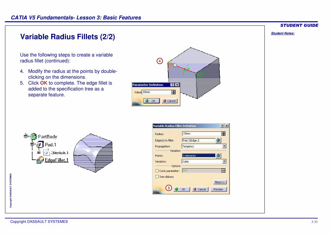
Variable Radius Fillets (2/2)
4
5
Use the following steps to create a variable radius fillet (continued):
4. Modify the radius at the points by double-clicking on the dimensions.
5. Click OK to complete. The edge fillet is added to the specification tree as a separate feature.
Student Notes:
CATIA V5 Fundamentals- Lesson 3: Basic Features ������������
Copyright DASSAULT SYSTEMES 3-34
Cop
yrig
ht D
AS
SA
ULT
SY
STE
ME
S
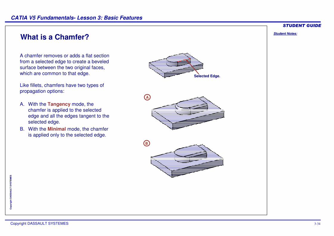
What is a Chamfer?
Selected Edge.
A
B
A chamfer removes or adds a flat section from a selected edge to create a beveled surface between the two original faces, which are common to that edge.
Like fillets, chamfers have two types of propagation options:
A. With the Tangency mode, the chamfer is applied to the selected edge and all the edges tangent to the selected edge.
B. With the Minimal mode, the chamfer is applied only to the selected edge.
Student Notes:
CATIA V5 Fundamentals- Lesson 3: Basic Features ������������
Copyright DASSAULT SYSTEMES 3-35
Cop
yrig
ht D
AS
SA
ULT
SY
STE
ME
S
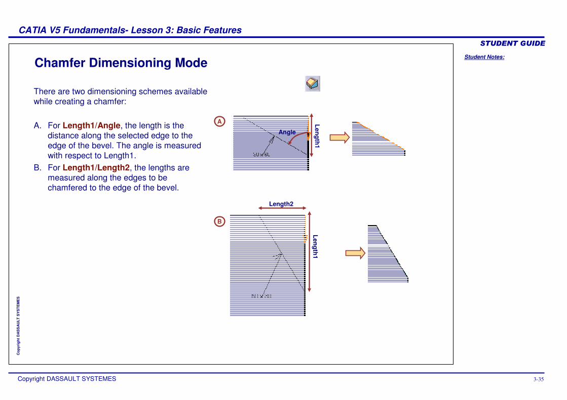
Chamfer Dimensioning Mode
Length1
Angle
A
Length1
Length2
B
There are two dimensioning schemes available while creating a chamfer:
A. For Length1/Angle, the length is the distance along the selected edge to the edge of the bevel. The angle is measured with respect to Length1.
B. For Length1/Length2, the lengths are measured along the edges to be chamfered to the edge of the bevel.
Student Notes:
CATIA V5 Fundamentals- Lesson 3: Basic Features ������������
Copyright DASSAULT SYSTEMES 3-36
Cop
yrig
ht D
AS
SA
ULT
SY
STE
ME
S
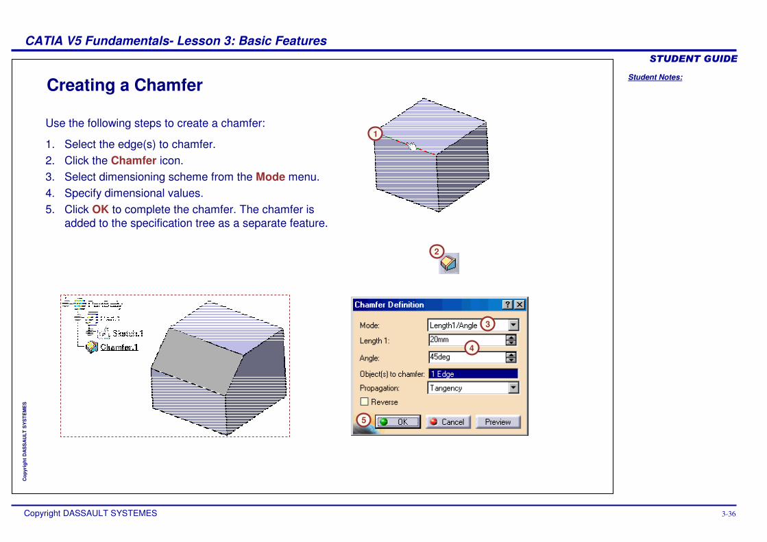
Creating a Chamfer
2
1
4
3
5
Use the following steps to create a chamfer:
1. Select the edge(s) to chamfer.2. Click the Chamfer icon.3. Select dimensioning scheme from the Mode menu.4. Specify dimensional values.5. Click OK to complete the chamfer. The chamfer is
added to the specification tree as a separate feature.
Student Notes:
CATIA V5 Fundamentals- Lesson 3: Basic Features ������������
Copyright DASSAULT SYSTEMES 3-37
Cop
yrig
ht D
AS
SA
ULT
SY
STE
ME
S
Recommendations for FilletsIn this section, you will be given a recommendation to help during the creation of fillets.
Student Notes:
CATIA V5 Fundamentals- Lesson 3: Basic Features ������������
Copyright DASSAULT SYSTEMES 3-38
Cop
yrig
ht D
AS
SA
ULT
SY
STE
ME
S
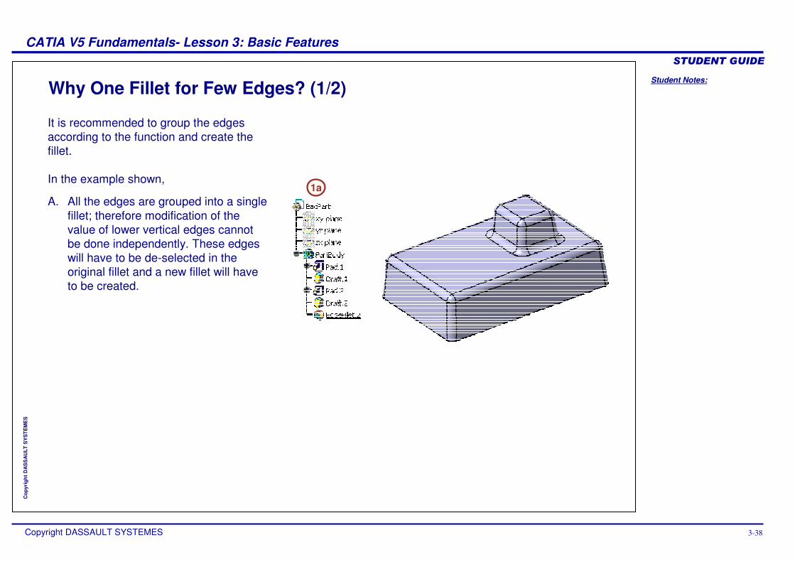
A. All the edges are grouped into a single fillet; therefore modification of the value of lower vertical edges cannot be done independently. These edges will have to be de-selected in the original fillet and a new fillet will have to be created.
Why One Fillet for Few Edges? (1/2)
1a
It is recommended to group the edges according to the function and create the fillet.
In the example shown,
Student Notes:
CATIA V5 Fundamentals- Lesson 3: Basic Features ������������
Copyright DASSAULT SYSTEMES 3-39
Cop
yrig
ht D
AS
SA
ULT
SY
STE
ME
S
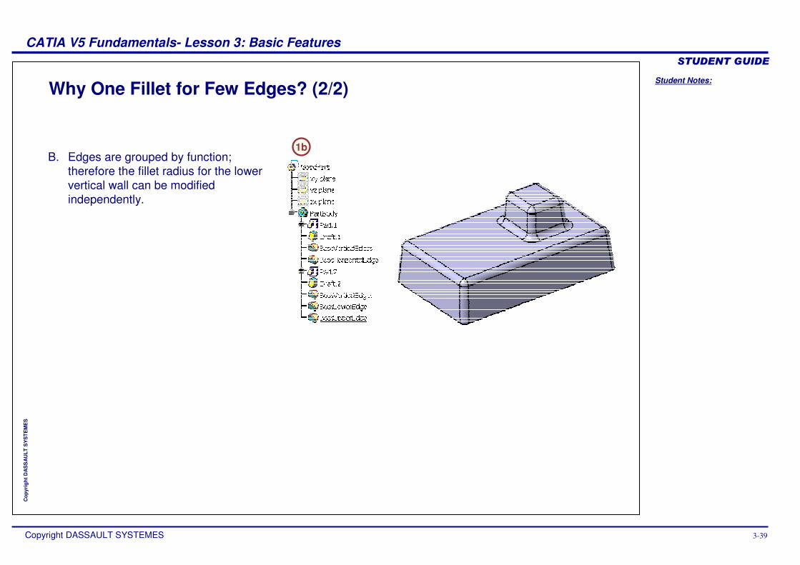
B. Edges are grouped by function; therefore the fillet radius for the lower vertical wall can be modified independently.
Why One Fillet for Few Edges? (2/2)
1b
Student Notes:
CATIA V5 Fundamentals- Lesson 3: Basic Features ������������
Copyright DASSAULT SYSTEMES 3-40
Cop
yrig
ht D
AS
SA
ULT
SY
STE
ME
S
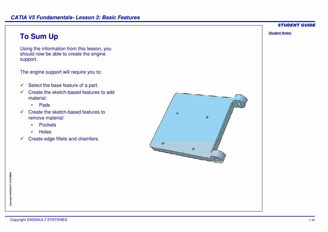
To Sum UpUsing the information from this lesson, you should now be able to create the engine support.
The engine support will require you to:
� Select the base feature of a part.� Create the sketch-based features to add
material:• Pads
� Create the sketch-based features to remove material:
• Pockets• Holes
� Create edge fillets and chamfers.
Student Notes:
CATIA V5 Fundamentals- Lesson 3: Basic Features ������������
Copyright DASSAULT SYSTEMES 3-41
Cop
yrig
ht D
AS
SA
ULT
SY
STE
ME
S
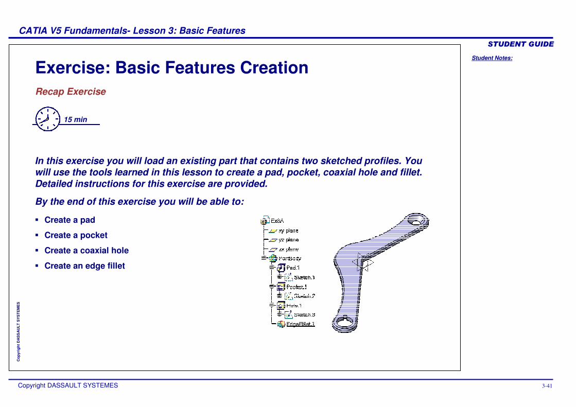
Exercise: Basic Features CreationRecap Exercise
15 min
In this exercise you will load an existing part that contains two sketched profiles. You will use the tools learned in this lesson to create a pad, pocket, coaxial hole and fillet. Detailed instructions for this exercise are provided.
By the end of this exercise you will be able to:
� Create a pad
� Create a pocket
� Create a coaxial hole
� Create an edge fillet
Student Notes:
CATIA V5 Fundamentals- Lesson 3: Basic Features ������������
Copyright DASSAULT SYSTEMES 3-42
Cop
yrig
ht D
AS
SA
ULT
SY
STE
ME
S
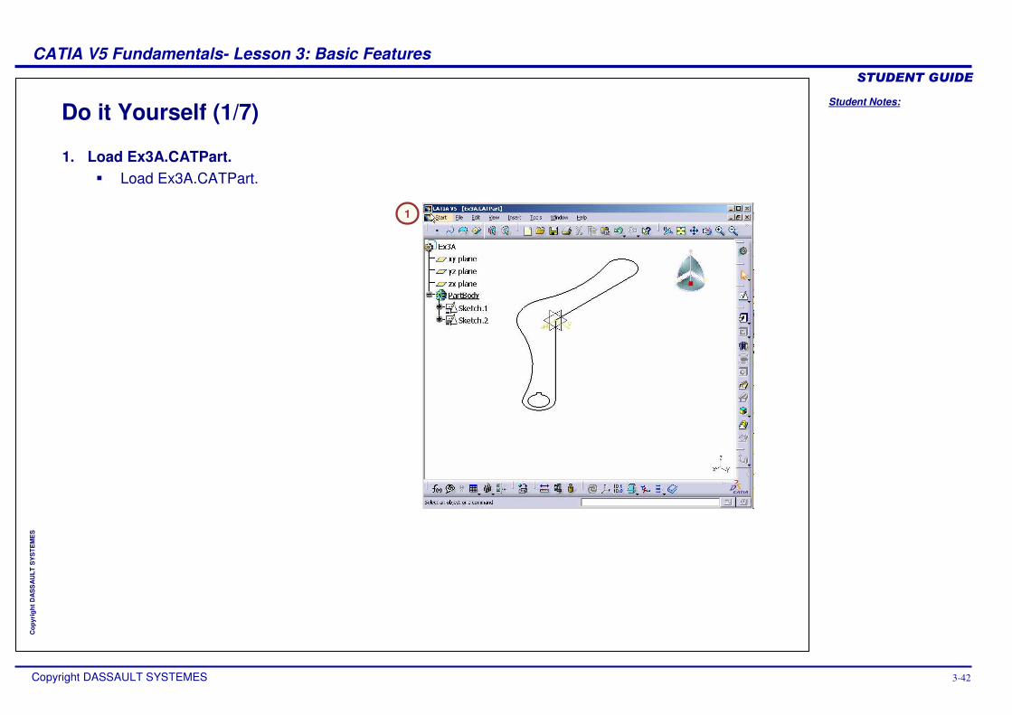
Do it Yourself (1/7)
1
1. Load Ex3A.CATPart. � Load Ex3A.CATPart.
Student Notes:
CATIA V5 Fundamentals- Lesson 3: Basic Features ������������
Copyright DASSAULT SYSTEMES 3-43
Cop
yrig
ht D
AS
SA
ULT
SY
STE
ME
S
Do it Yourself (2/7)2a
2b
2c
2d
2e
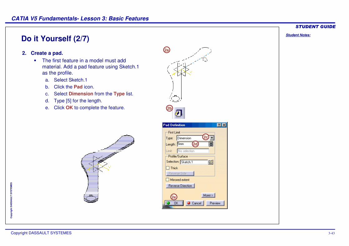
2. Create a pad.� The first feature in a model must add
material. Add a pad feature using Sketch.1 as the profile.
a. Select Sketch.1b. Click the Pad icon.c. Select Dimension from the Type list.d. Type [5] for the length.e. Click OK to complete the feature.
Student Notes:
CATIA V5 Fundamentals- Lesson 3: Basic Features ������������
Copyright DASSAULT SYSTEMES 3-44
Cop
yrig
ht D
AS
SA
ULT
SY
STE
ME
S
Do it Yourself (3/7)
3a
3b
3c
3d
3e
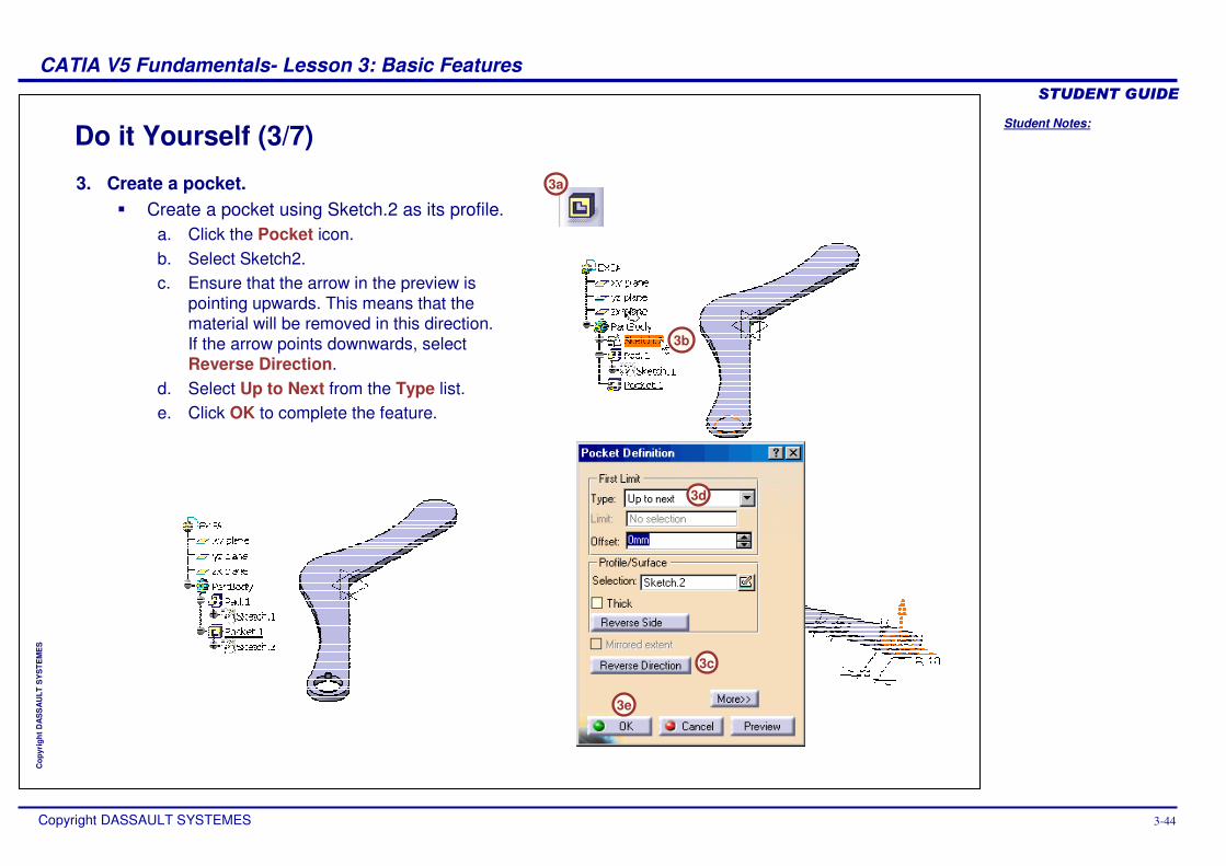
3. Create a pocket.� Create a pocket using Sketch.2 as its profile.
a. Click the Pocket icon.b. Select Sketch2.c. Ensure that the arrow in the preview is
pointing upwards. This means that the material will be removed in this direction. If the arrow points downwards, select Reverse Direction.
d. Select Up to Next from the Type list.e. Click OK to complete the feature.
Student Notes:
CATIA V5 Fundamentals- Lesson 3: Basic Features ������������
Copyright DASSAULT SYSTEMES 3-45
Cop
yrig
ht D
AS
SA
ULT
SY
STE
ME
S
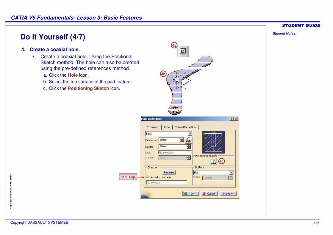
Do it Yourself (4/7)4a
4b
4c
4. Create a coaxial hole.� Create a coaxial hole. Using the Positional
Sketch method. The hole can also be created using the pre-defined references method.
a. Click the Hole icon.b. Select the top surface of the pad feature.c. Click the Positioning Sketch icon.
Conf. Dep.
Student Notes:
CATIA V5 Fundamentals- Lesson 3: Basic Features ������������
Copyright DASSAULT SYSTEMES 3-46
Cop
yrig
ht D
AS
SA
ULT
SY
STE
ME
S
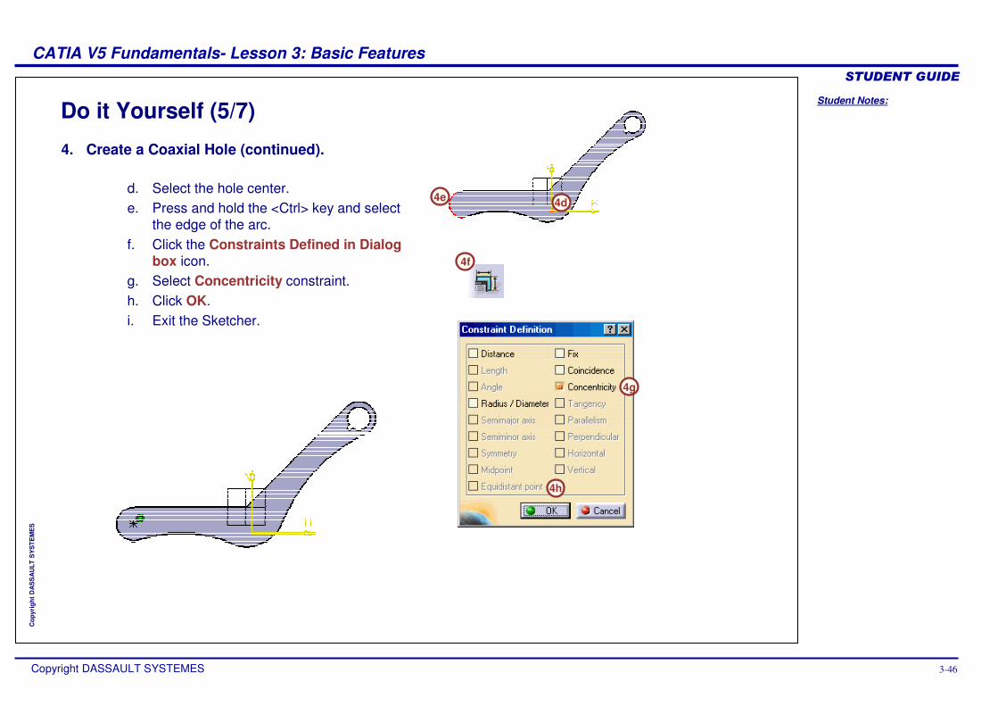
Do it Yourself (5/7)
4f
4d4e
4g
4h
4. Create a Coaxial Hole (continued).
d. Select the hole center. e. Press and hold the <Ctrl> key and select
the edge of the arc.f. Click the Constraints Defined in Dialog
box icon.g. Select Concentricity constraint.h. Click OK.i. Exit the Sketcher.
Student Notes:
CATIA V5 Fundamentals- Lesson 3: Basic Features ������������
Copyright DASSAULT SYSTEMES 3-47
Cop
yrig
ht D
AS
SA
ULT
SY
STE
ME
S
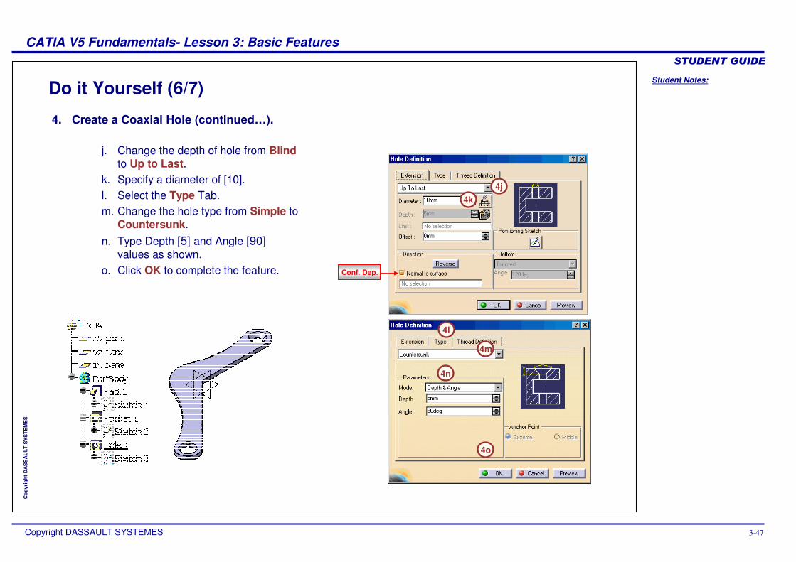
Do it Yourself (6/7)
4j
4l
4m
4n
4o
4k
4. Create a Coaxial Hole (continued…).
j. Change the depth of hole from Blindto Up to Last.
k. Specify a diameter of [10].l. Select the Type Tab.m. Change the hole type from Simple to
Countersunk.n. Type Depth [5] and Angle [90]
values as shown.o. Click OK to complete the feature. Conf. Dep.
Student Notes:
CATIA V5 Fundamentals- Lesson 3: Basic Features ������������
Copyright DASSAULT SYSTEMES 3-48
Cop
yrig
ht D
AS
SA
ULT
SY
STE
ME
S
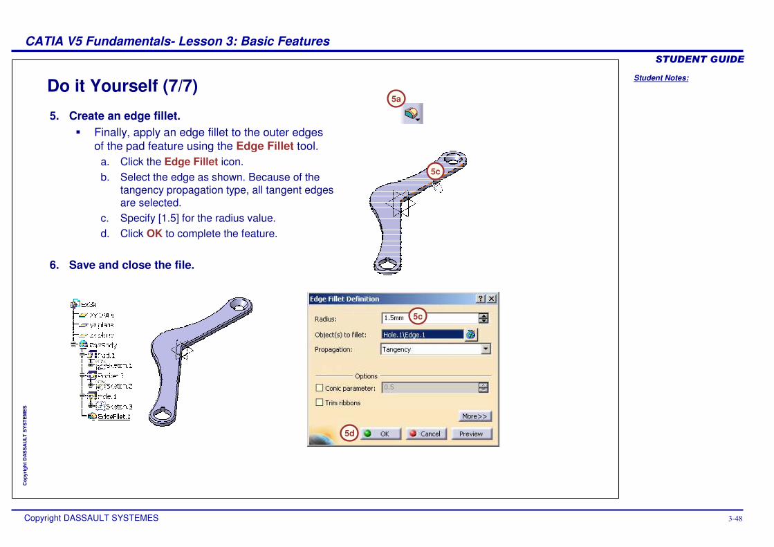
Do it Yourself (7/7)5a
5c
5d
5c
5. Create an edge fillet.� Finally, apply an edge fillet to the outer edges
of the pad feature using the Edge Fillet tool.a. Click the Edge Fillet icon.b. Select the edge as shown. Because of the
tangency propagation type, all tangent edges are selected.
c. Specify [1.5] for the radius value.d. Click OK to complete the feature.
6. Save and close the file.
Student Notes:
CATIA V5 Fundamentals- Lesson 3: Basic Features ������������
Copyright DASSAULT SYSTEMES 3-49
Cop
yrig
ht D
AS
SA
ULT
SY
STE
ME
S
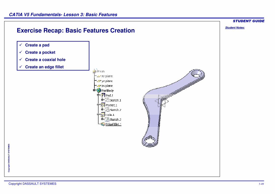
Exercise Recap: Basic Features Creation
� Create a pad
� Create a pocket
� Create a coaxial hole
� Create an edge fillet
Student Notes:
CATIA V5 Fundamentals- Lesson 3: Basic Features ������������
Copyright DASSAULT SYSTEMES 3-50
Cop
yrig
ht D
AS
SA
ULT
SY
STE
ME
S
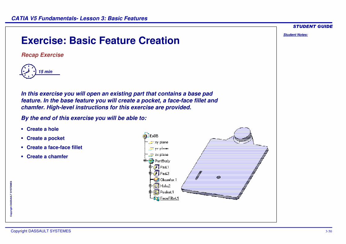
Exercise: Basic Feature CreationRecap Exercise
15 min
In this exercise you will open an existing part that contains a base pad feature. In the base feature you will create a pocket, a face-face fillet and chamfer. High-level instructions for this exercise are provided.
By the end of this exercise you will be able to:
� Create a hole
� Create a pocket
� Create a face-face fillet
� Create a chamfer
Student Notes:
CATIA V5 Fundamentals- Lesson 3: Basic Features ������������
Copyright DASSAULT SYSTEMES 3-51
Cop
yrig
ht D
AS
SA
ULT
SY
STE
ME
S
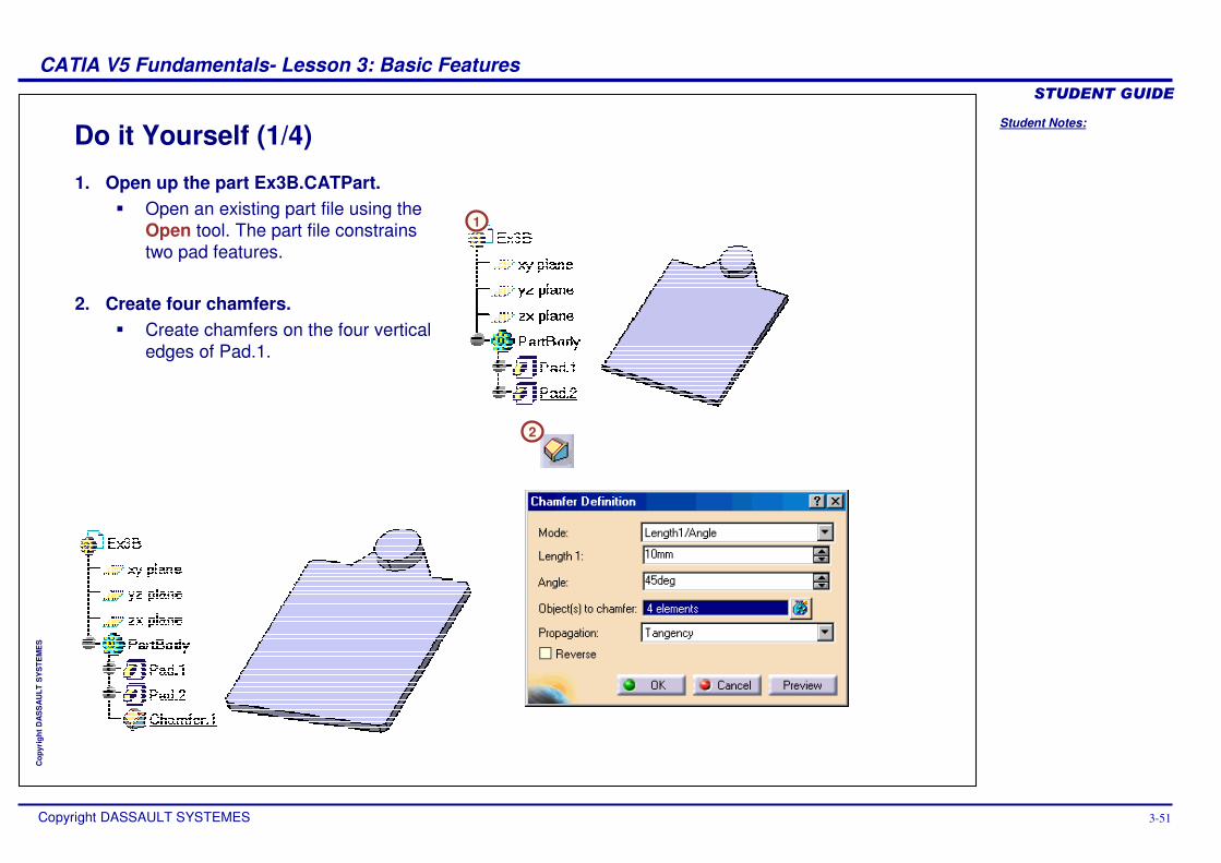
Do it Yourself (1/4)
2
1
1. Open up the part Ex3B.CATPart.� Open an existing part file using the
Open tool. The part file constrains two pad features.
2. Create four chamfers. � Create chamfers on the four vertical
edges of Pad.1.
Student Notes:
CATIA V5 Fundamentals- Lesson 3: Basic Features ������������
Copyright DASSAULT SYSTEMES 3-52
Cop
yrig
ht D
AS
SA
ULT
SY
STE
ME
S
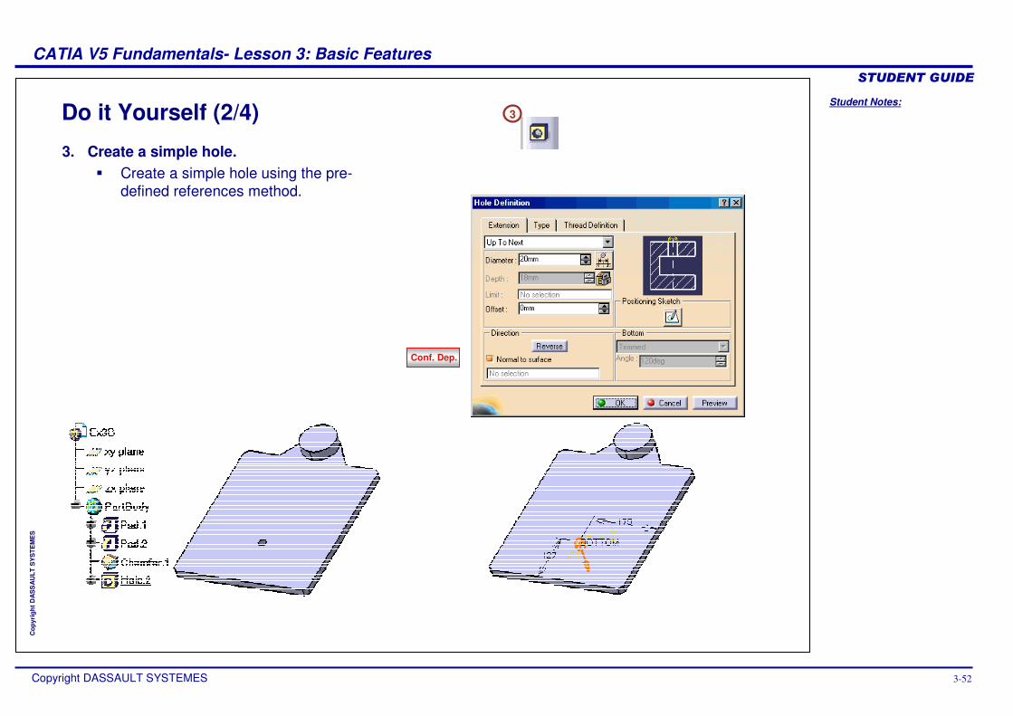
Do it Yourself (2/4) 3
3. Create a simple hole.� Create a simple hole using the pre-
defined references method.
Conf. Dep.
Student Notes:
CATIA V5 Fundamentals- Lesson 3: Basic Features ������������
Copyright DASSAULT SYSTEMES 3-53
Cop
yrig
ht D
AS
SA
ULT
SY
STE
ME
S
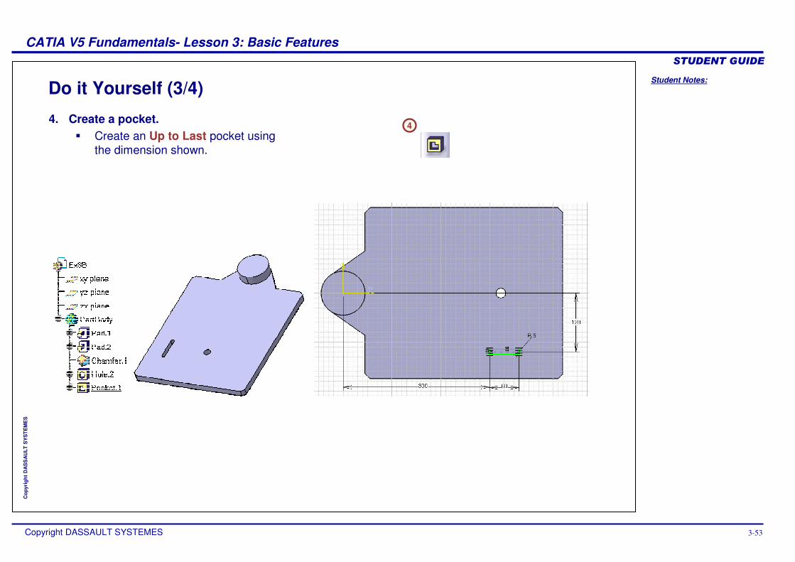
Do it Yourself (3/4)
44. Create a pocket.
� Create an Up to Last pocket using the dimension shown.
Student Notes:
CATIA V5 Fundamentals- Lesson 3: Basic Features ������������
Copyright DASSAULT SYSTEMES 3-54
Cop
yrig
ht D
AS
SA
ULT
SY
STE
ME
S
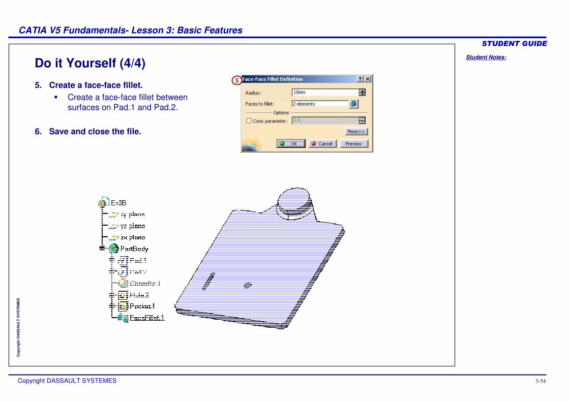
Do it Yourself (4/4) 5
5. Create a face-face fillet.� Create a face-face fillet between
surfaces on Pad.1 and Pad.2.
6. Save and close the file.
Student Notes:
CATIA V5 Fundamentals- Lesson 3: Basic Features ������������
Copyright DASSAULT SYSTEMES 3-55
Cop
yrig
ht D
AS
SA
ULT
SY
STE
ME
S
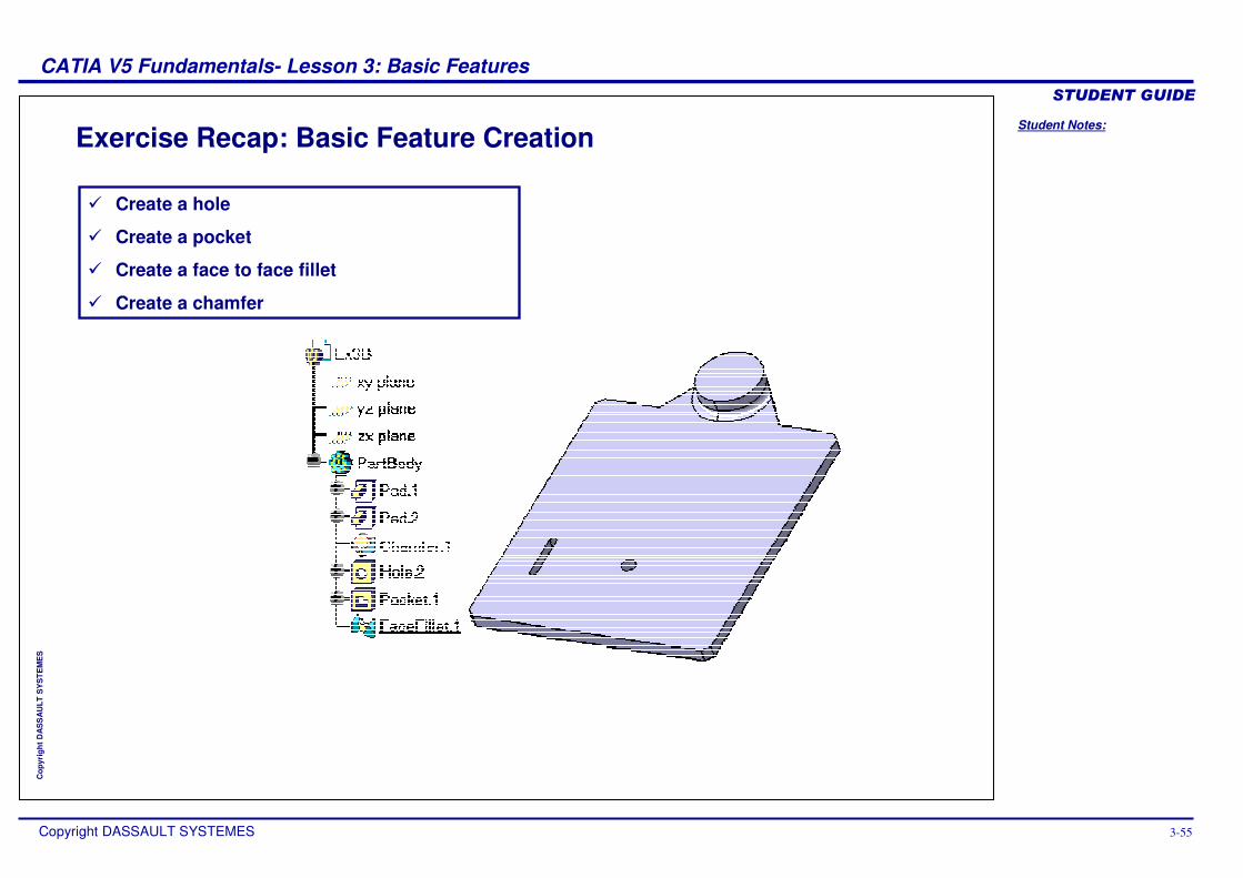
Exercise Recap: Basic Feature Creation
� Create a hole
� Create a pocket
� Create a face to face fillet
� Create a chamfer
Student Notes:
CATIA V5 Fundamentals- Lesson 3: Basic Features ������������
Copyright DASSAULT SYSTEMES 3-56
Cop
yrig
ht D
AS
SA
ULT
SY
STE
ME
S
Exercise: Basic Features CreationRecap Exercise
10 min
In this exercise, you will create a part that contains features taught in this and the previous lessons. You will use the tools you have learned to complete the exercise with no detailed instructions.
By the end of this exercise you will be able to:
� Create a pad
� Create a pocket
� Create a countersunk hole
� Create an edge fillet
Student Notes:
CATIA V5 Fundamentals- Lesson 3: Basic Features ������������
Copyright DASSAULT SYSTEMES 3-57
Cop
yrig
ht D
AS
SA
ULT
SY
STE
ME
S
Do it Yourself
1. Create the following part.
Student Notes:
CATIA V5 Fundamentals- Lesson 3: Basic Features ������������
Copyright DASSAULT SYSTEMES 3-58
Cop
yrig
ht D
AS
SA
ULT
SY
STE
ME
S
Exercise Recap: Basic Features Creation
� Create a pad
� Create a pocket
� Create a countersunk hole
� Create an edge fillet
Student Notes:
CATIA V5 Fundamentals- Lesson 3: Basic Features ������������
Copyright DASSAULT SYSTEMES 3-59
Cop
yrig
ht D
AS
SA
ULT
SY
STE
ME
S
Exercise: Edge and Face-Face Fillets Recap Exercise
10 min
In this exercise you will create a part that contains features taught in this and the previous lessons. You will use the tools you have learned to complete the exercise with no detailed instructions.
By the end of this exercise you will be able to:
� Create a face-face fillet
� Create the necessary additional fillet in order to enable face-face fillet creation
Student Notes:
CATIA V5 Fundamentals- Lesson 3: Basic Features ������������
Copyright DASSAULT SYSTEMES 3-60
Cop
yrig
ht D
AS
SA
ULT
SY
STE
ME
S
Do it Yourself
Ex3D_A.CATPart Ex3D_B.CATPart
1. Add edge fillets to the top faces of the following parts.2. Add face-face fillets by determining the radius yourself. Afterwards add
bottom edge fillets.3. Change the distance between the cylindrical / drafted pads and the
preliminary edge fillet’s radius and examine the impact on the face-face fillet
Student Notes:
CATIA V5 Fundamentals- Lesson 3: Basic Features ������������
Copyright DASSAULT SYSTEMES 3-61
Cop
yrig
ht D
AS
SA
ULT
SY
STE
ME
S
Exercise Recap: Edge and Face-Face Fillets
� Create edge fillets in order to enable face-face fillet creation
� Create face-face fillets
Student Notes:
CATIA V5 Fundamentals- Lesson 3: Basic Features ������������
Copyright DASSAULT SYSTEMES 3-62
Cop
yrig
ht D
AS
SA
ULT
SY
STE
ME
S
Case Study: Basic FeaturesRecap Exercise
20 min
In this exercise you will create the case study model. Recall the design intent of this model:� The sketch must not contain any internal loops.
� Each element on this model will need to be created as a separate feature. Creating the elements separately makes it easy to make modifications later.
� The four center holes must be created as one feature.
� One hole would be created first and then patterned to create the other three holes. Since the requirement is to have them created as one feature, a pocket will need to be used.
� The fillets and the chamfer may need to be removed in downstream applications.
� The fillets and the chamfer cannot be created within the sketched profile; they will have to be created as separate features.
Using the techniques discussed so far, create the model without detailed instructions.
Student Notes:
CATIA V5 Fundamentals- Lesson 3: Basic Features ������������
Copyright DASSAULT SYSTEMES 3-63
Cop
yrig
ht D
AS
SA
ULT
SY
STE
ME
S
Do It Yourself: Drawing of the Engine Support (1/2)
1
2
3
4
5
6
You will be required to create the following features: