printed on recycled paper Field Operations Division TEXAS COMMISSION ON ENVIRONMENTAL QUALITY RG-348 Revised July 2005 Complying with the Edwards Aquifer Rules Technical Guidance on Best Management Practices
Transcript
printed onrecycled paper
Field Operations Division
TEXAS COMMISSION ON ENVIRONMENTAL QUALITY
RG-348Revised July 2005
Complying with theEdwards Aquifer RulesTechnical Guidance on BestManagement Practices
Complying with theEdwards Aquifer RulesTechnical Guidance on Best
Management Practices
Prepared for Field Operations Division
by Michael E. Barrett, Ph.D., P.E.Center for Research in Water Resources
Bureau of Engineering ResearchUniversity of Texas at Austin
RG-348 (Revised)July 2005
The TCEQ is an equal opportunity/affirmative action employer. The agency does not allow discriminationon the basis of race, color, religion, national origin, sex, disability, age, sexual orientation or veteran status.In compliance with the Americans with Disabilities Act, this document may be requested in alternate formats
by contacting the TCEQ at 512/239-0028, Fax 239-4488, or 1-800-RELAY-TX (TDD),or by writing P.O. Box 13087, Austin, TX 78711-3087.
Kathleen Hartnett White, ChairmanR. B. “Ralph” Marquez, Commissioner
Larry R. Soward, Commissioner
Glenn Shankle, Executive Director
Authorization to use or reproduce any original material contained in this publication—that is, notobtained from other sources—is freely granted. The com-mission would appreciate acknowledgment.
Copies of this publication are available for public use through the Texas State Library, other statedepository libraries, and the TCEQ Library, in compliance with state depository law. For more informationon TCEQ publications, call 512/239-0028 or visit our Web site at:
www.tceq.state.tx.us/publications
Published and distributedby the
Texas Commission on Environmental QualityPO Box 13087
Austin TX 78711-3087
i
Preface
The Edwards Aquifer is one of the most valuable resources in the central Texas area. This aquifer provides water for municipal, industrial, and agricultural uses as well as sustaining a number of rare and endangered species. To preserve these beneficial uses, Texans must protect water quality in this aquifer from degradation resulting from human activities. The Edwards Aquifer rules are an effective mechanism we can use to protect this valuable resource. Found in Title 30 Texas Administrative Code Chapter 213, these rules address activities that could pose a threat to water quality in the Edwards Aquifer, including wells and springs fed by the aquifer and water sources to the aquifer, including uplands areas draining directly to it and surface streams. These rules apply specifically to the Edwards Aquifer in eight counties and are not intended for any other aquifers in Texas. To keep this manual current, we will periodically review and revise material that needs updating in response to changes in the rules or the availability of new or improved technology. We will make these updated portions available through our Publications Unit and through the Edwards Aquifer Protection Program page on our Web site (http://www.tnrcc.state.tx.us/eapp). We would like to thank Michael E. Barrett, Ph.D., P.E., Center for Research in Water Resources, Bureau of Engineering Research, University of Texas at Austin for his contribution of drafting and editing the chapters containing technical guidance (see his note below). We would also like to thank the members of the regulated community who participated through our Technical Review Work Group in the development of this manual. Dr. Barrett adds: The material in the technical guidance chapters of this manual was adapted primarily from guidance documents adopted by other state, regional, and municipal agencies. Preference was given to materials developed in Texas. Primary source included the City of Austin, the Lower Colorado River Authority, and the North Central Texas Council of Governments. Material from other parts of the country was modified to conform to specific climatic, soil, geologic, and other constraints present in the contributing and recharge zones of the Edwards Aquifer. This guidance document was greatly improved by the contributions and comments of many readers. In particular, the staffs of the Austin and San Antonio regional offices of the TCEQ provided material as well as comments. Helpful suggestions were also received from municipalities, agencies responsible for water quality, and many in the consulting industry. I will refrain from naming these parties for fear of implying their approval of all aspects of this manual; nevertheless, their contributions were greatly appreciated.
ii
Table of Contents
CHAPTER 1 TEMPORARY BEST MANAGEMENT PRACTICES..........................1-1
1.1 INTRODUCTION .................................................................................................1-1 1.2 GENERAL GUIDELINES ......................................................................................1-2 1.3 TEMPORARY EROSION CONTROL BMPS ...........................................................1-9
CHAPTER 4 INNOVATIVE TECHNOLOGY: USE AND EVALUATION ..............4-1
4.1 QUALITY ASSURANCE PROJECT PLAN (QAPP) .................................................4-1 4.2 INFORMATION ABOUT THE TECHNOLOGY..........................................................4-2 4.3 STORMWATER FIELD SAMPLING PROCEDURES .................................................4-4 4.4 FULL-SCALE LABORATORY STUDIES ................................................................4-7 4.5 LABORATORY QA PROCEDURES .......................................................................4-8 4.6 DATA MANAGEMENT PROCEDURES ..................................................................4-8 4.7 DATA REVIEW , VERIFICATION, AND VALIDATION............................................4-9
CHAPTER 5 MANAGEMENT OF SENSITIVE FEATURES ....................................5-1
5.1 PROTECTION OF SENSITIVE FEATURES IDENTIFIED IN THE GEOLOGICAL ASSESSMENT.................................................................................................................5-1
5.1.1 Small Depressions with Earthen Bottoms.................................................... 5-1 5.1.2 Sensitive Features ........................................................................................ 5-2 5.1.3 Caves............................................................................................................ 5-3
5.2 PROTECTION OF FEATURES IDENTIFIED DURING CONSTRUCTION .....................5-8
CHAPTER 6 EXAMPLE CALCULATIONS...............................................................6-1
Table 3-8 One-year, Three-hour Storm by County (TxDOT, 1998) ...........................3-103
Table 5-1 Minimum Protective Standards for Sewer and Storm Drain Trenches .........5-10
1-1
1 Temporary Best Management Practices
1.1 Introduction The two most basic categories of temporary control methods for construction-generated pollution are erosion and sediment controls. Erosion controls are used to prevent soil on the construction site from being mobilized and transported by stormwater runoff. Vegetative stabilization, slope coverings, and diversion of runoff away from exposed areas can effectively prevent erosion. Sediment controls may be considered as the second line of defense and include sedimentation ponds, silt fences, berms and other temporary barriers that temporarily detain the runoff. Runoff velocities are reduced in these controls allowing sediment in the runoff to settle out. This chapter gives instructions for installation of the most commonly used erosion and sediment control practices. Each practice is presented with a list of guidelines for proper installation and a compilation of common trouble points. Additional information on these and other practices can be found in other manuals. Contractors are encouraged to install and maintain practices carefully, in a professional manner. Minor adjustments should be anticipated to assure proper performance. Intensive maintenance and extensive use of vegetation, mulch, and other ground covers may be required to achieve optimum performance. We recommend very strongly, therefore, that such erosion and sediment control efforts be specified clearly in the general construction contract and that any unexpected expenses be approved before they are incurred. When these controls are removed after final stabilization of the site, it is important to also remove or stabilize any accumulated sediment. Periodic inspection and maintenance is vital to the performance of erosion and sedimentation control measures. It is recommended that all temporary erosion controls be inspected weekly and after every rainfall; however, daily inspections may be warranted when environmentally sensitive features are located on or immediately adjacent to the site. If not properly maintained, some practices may cause more damage than they prevent. Always evaluate the consequences of a measure failing when considering which control measure to use, since failure of a practice may be hazardous or damaging to both people and property. For example, a large sediment basin failure can have disastrous results; low points in dikes can cause major gullies to form on a fill slope. It is essential to inspect all practices to determine that they are working properly and to ensure that problems are corrected as soon as they develop. Assign an individual responsibility for routine checks of operating erosion and sedimentation control practices.
1-2
1.2 General Guidelines The following planning and construction practices were described by the U.S. Environmental Protection Agency (EPA, 1993) and North Carolina (North Carolina, 1993) to illustrate the types of measures that can be applied successfully to achieve a reduction in the amount of erosion occurring on active construction sites. These practices are used to reduce the amount of sediment that is detached during construction and to prevent sediment from entering runoff. Erosion control is based on two main concepts: (1) disturb the smallest area of land possible for the shortest period of time, and (2) stabilize disturbed soils to prevent erosion from occurring. Development Siting Review and consider all existing conditions in the initial site selection for the project. Select a site that is suitable rather than force the terrain to conform to development needs (Figure 1-1). Ensure that development features follow natural contours. Steep slopes, areas subject to flooding, and highly erodible soils severely limit a site’s use, while level, well-drained areas offer few restrictions. Any modification of a site’s drainage features or topography requires protection from erosion and sedimentation.
Figure 1-1 Examples of Proper and Improper Siting (North Carolina, 1993)
Project Scheduling Often a project can be scheduled during the time of year that the erosion potential of the site is relatively low. In many parts of the country, there is a certain period of the year when erosion potential is relatively low and construction scheduling could be very
1-3
effective. In central Texas, rainfall amounts are generally lower during July and August and the hot temperatures quickly dry out exposed soils. During the wetter months (spring and fall), construction vehicles can easily turn the soft, wet ground into mud, which is more easily washed offsite. Scheduling can be a very effective means of reducing the hazards of erosion. Schedule construction activities to minimize the exposed area and the duration of exposure. In scheduling, take into account the season and the weather forecast. Stabilize disturbed areas as quickly as possible. Avoid area wide clearance of construction sites. Plan and stage land disturbance activities so that only the area currently under construction is exposed. As soon as the grading and construction in an area are complete, the area should be stabilized. Material Management Locate potential nonpoint pollutant sources away from steep slopes, streams, and critical areas. Material stockpiles, borrow areas, access roads, and other land-disturbing activities can often be located away from critical areas such as steep slopes, highly erodible soils, and areas that drain directly into geologically sensitive features. The exposure of litter, construction debris, and chemicals to stormwater should be minimized to prevent them from becoming a pollutant source. Daily litter removal and screening outfalls and storm drain inlets may help retain these materials onsite. Stockpile topsoil and reapply to revegetate site. Because of the high organic content of topsoil, it cannot be used as fill material or under pavement. Topsoil is typically removed when a site is cleared. Since topsoil is essential to establish new vegetation, it should be stockpiled and then reapplied to the site for revegetation, if appropriate. Although topsoil salvaged from the existing site can often be used, it must meet certain standards and topsoil may need to be imported onto the site if the existing topsoil is not adequate for establishing new vegetation. Cover or stabilize topsoil stockpiles. Unprotected stockpiles are very prone to erosion and therefore stockpiles must be protected. Small stockpiles can be covered with a tarp to prevent erosion. Large stockpiles should be stabilized with erosion blankets, seeding, and/or mulching. In addition, spoils should not be stored within the 100-year floodplain where they can be disturbed during high flow conditions. Vegetation Protection By clearing only those areas immediately essential for completing site construction, buffer zones are preserved and soil remains undisturbed until construction begins (Figure 1-2). Physical markers, such as tape, signs, or barriers, indicating the limits of land disturbance, can ensure that equipment operators know the proposed limits of clearing.
1-4
The area of the watershed that is exposed to construction is important in determining the net amount of erosion. Reducing the extent of the disturbed area will ultimately reduce sediment loads to surface waters. Existing or newly planted vegetation that has been planted to stabilize disturbed areas should be protected by routing construction traffic around the areas and protecting natural vegetation with fencing, tree armoring, retaining walls, or tree wells. Avoid disturbing vegetation on steep slopes or other critical areas. Where possible, construction traffic should travel over areas that must be disturbed for other construction activity. This practice will reduce the area that is cleared and susceptible to erosion. Tree armoring protects tree trunks from being damaged by construction equipment. Fencing can also protect tree trunks, but should be placed at the tree’s drip line so that construction equipment is kept away from the tree. The tree drip line is the minimum area around a tree in which the tree’s root system should not be disturbed by cut, fill, or soil compaction caused by heavy equipment. When cutting or filling must be done near a tree, a retaining wall or tree well should be used to minimize the cutting of the tree’s roots or the quantity of fill placed over the roots.
Figure 1-2 Example of Conservative Site Clearing (North Carolina, 1993)
Use wind erosion controls. Although not required by the rules, wind erosion controls can reduce the impact of construction on adjacent tracts. These controls limit the movement of dust from disturbed soil surfaces and include many different practices. Wind barriers block air currents and are effective in controlling soil blowing. Many different materials can be used as wind barriers, including solid board fences, snow fences, and bales of hay. Sprinkling moistens the soil surface with water and must be repeated as needed to be effective for preventing wind erosion; however, applications must be monitored to prevent excessive runoff and erosion.
1-5
Protect Area from Upgradient runoff Protect areas to be disturbed from stormwater runoff. Use dikes, diversions, and waterways to interrupt runoff and divert it away from cut-and-fill slopes or other disturbed areas. To reduce on-site erosion, install these measures before clearing and grading. Earth dikes, perimeter dikes or swales, or diversions can be used to intercept and convey runoff above disturbed areas (Figure 1-3). An earth dike is a temporary berm or ridge of compacted soil that channels water around or away from disturbed areas. A perimeter dike/swale or diversion is a swale with a supporting ridge on the lower side that is constructed from the soil excavated from the adjoining swale. These practices should be used to intercept flow from denuded areas or newly seeded areas to keep the disturbed areas from being eroded from the uphill runoff. The structures should be stabilized within 14 days of installation or as soon as practicable with vegetation, slope coverings or other appropriate erosion prevention measures. A pipe slope drain, also known as a pipe drop structure, is a temporary pipe placed from the top of a slope to the bottom of the slope to convey concentrated runoff down the slope without causing erosion.
Figure 1-3 Diversion of Runoff away from Construction Area (North Carolina, 1993)
Reduce Runoff Velocities Keep runoff velocities low. Clearing existing vegetation reduces the surface roughness and infiltration rate and thereby increases runoff velocities and volumes. Use measures that break the slopes (Figure 1-4) to reduce the problems associated with concentrated flow volumes and runoff velocities. Practical ways to reduce velocities include conveying stormwater runoff away from steep slopes to stabilized outlets, preserving natural vegetation where possible, and mulching and vegetating exposed areas immediately after construction.
1-6
Figure 1-4 Slow Runoff by Breaking Slopes (North Carolina, 1993)
Benches, terraces, or ditches break up a slope by providing areas of low slope in the reverse direction. This keeps water from proceeding down the slope at increasing volume and velocity. Instead, the flow is directed to a suitable outlet, such as a sediment basin or trap. The frequency of benches, terraces, or ditches will depend on the erodibility of the soils, steepness and length of the slope, and rock outcrops. This practice should be used if there is a potential for erosion along the slope. Use retaining walls. Often retaining walls can be used to decrease the steepness of a slope. If the steepness of a slope is reduced, the runoff velocity is decreased and therefore, the erosion potential is decreased. Retaining walls also may actually encourage water to infiltrate rather than runoff, thereby helping maintain the natural hydrologic characteris tics of a site. Provide linings for urban runoff conveyance channels. Construction often increases the velocity and volume of runoff, which causes erosion in newly constructed or existing urban runoff conveyance channels. If the runoff during or after construction will cause erosion in a channel, the channel should be lined or flow control BMPs installed. The first choice of lining should be grass or sod since this reduces runoff velocities and provides water quality benefits through filtration and infiltration. If the velocity in the channel would erode the grass or sod, then riprap, concrete, or gabions can be used. Use check dams. Check dams are small, temporary dams constructed across a swale or channel. They can be constructed using gravel or straw bales. They are used to reduce the velocity of concentrated flow and, therefore, to reduce the erosion in a swale or channel. Check dams should be used when a swale or channel will be used for a short time and therefore it is not feasible or practical to line the channel or implement flow control BMPs.
1-7
Site Stabilization Removing the vegetative cover and altering the soil structure by clearing, grading, and compacting the surface increases an area’s susceptibility to erosion. Apply stabilizing measures as soon as possible after the land is disturbed (Figure 1-5). Plan and implement temporary or permanent vegetation, mulches, or other protective practices to correspond with construction activities. Protect channels from erosive forces by using protective linings and the appropriate channel design. Consider possible future repairs and maintenance of these practices in the design. Seeding establishes a vegetative cover on disturbed areas. Seeding is very effective in controlling soil erosion once a vegetative cover of about 80% has been established. However, often seeding and fertilizing do not produce as thick a vegetative cover as do seed and mulch or netting. Newly established vegetation does not have as extensive a root system as existing vegetation and therefore is more prone to erosion, especially on steep slopes. Care should be taken when fertilizing to avoid untimely or excessive application. Since the practice of seeding and fertilizing does not provide any protection during the time of vegetative establishment, it should be used only on favorable soils in very flat areas and not in sensitive areas.
Figure 1-5 Stabilization of Disturbed Areas (North Carolina, 1993)
The management of land by using ground cover reduces erosion by reducing the flow rate of runoff and the raindrop impact. Bare soils should be seeded or otherwise stabilized within 14 calendar days after final grading or where construction activity has temporarily ceased for more than 21 days. In very flat, non-sensitive areas with favorable soils, stabilization may involve simply seeding and fertilizing. Mulch and/or sod may be necessary on steeper slopes, for erodible soils, and near sensitive areas. Sediment that has escaped the site due to the failure of sediment and erosion controls should be removed as soon as possible to minimize offsite impacts. Permission should be obtained from adjacent landowners prior to offsite sediment removal.
1-8
Mulching/mats can be used to protect the disturbed area while vegetation becomes established. Mulching involves applying plant residues or other suitable materials on disturbed soil surfaces. Mulches/mats used include tacked straw, wood chips, and jute netting and are often covered by blankets or netting. Mulching alone should be used only for temporary protection of the soil surface or when permanent seeding is not feasible. The useful life of mulch varies with the material used and the amount of precipitation, but is approximately 2 to 6 months. During times of year when vegetation cannot be established, soil mulching should be applied to moderate slopes and soils that are not highly erodible. On steep slopes or highly erodible soils, multiple mulching treatments should be used. Interlocking ceramic materials, filter fabric, and netting are available for this purpose. Before stabilizing an area, it is important to have installed all sediment controls and diverted runoff away from the area to be planted. Runoff may be diverted away from denuded areas or newly planted areas using dikes, swales, or pipe slope drains to intercept runoff and convey it to a permanent channel or storm drain. Reserved topsoil may be used to revegetate a site if the stockpile has been covered and stabilized. Consideration should be given to maintenance when designing mulching and matting schemes. Plastic nets are often used to cover the mulch or mats; however, they can foul lawn mower blades if the area requires mowing. Sod can be used to permanently stabilize an area. Sodding provides immediate stabilization of an area and should be used in critical areas or where establishment of permanent vegetation by seeding and mulching would be difficult. Sodding is also a preferred option when there is high erosion potential during the period of vegetative establishment from seeding. Because of the hardy drought-resistant nature of wildflowers, they may be more beneficial as an erosion control practice than turf grass. While not as dense as turfgrass, wildflower thatches and associated grasses are expected to be as effective in erosion control and contaminant absorption. Because thatches of wildflowers do not need fertilizers, pesticides, or herbicides, and the need for watering is minimal, implementation of this practice may result in cost savings. In 1987, Howard County, Maryland, spent $690.00 per acre to maintain turfgrass areas, compared to only $31.00 per acre for wildflower meadows. A wildflower stand requires several years to become established; however, maintenance requirements are minimal once the area is established. Plan for Temporary Structural Controls Retain Sediment on the Site. Even with careful planning, some erosion is unavoidable. The resulting sediment must be trapped on the site. Plan the location where sediment deposition will occur and maintain access for cleanout. Protect low points below disturbed areas by building barriers to reduce sediment loss. Whenever possible, plan and construct sediment traps and basins before other land-disturbing activities (Figure 1-6).
1-9
Figure 1-6 Retention of Eroded Sediment on Site
1.3 Temporary Erosion Control BMPs Temporary erosion controls should be considered the first line of defense for prevention of water pollution during construction activities. It is much simpler to maintain the soil cover than to trap the sediment once it has been mobilized. In addition effective erosion prevention can result in cost savings, since repair of erosion damage can be minimized. The primary goal of erosion control is to divert runoff away from unstable areas or to provide a stable surface that will resist the effects of rain and runoff. The principle measures for diverting runoff include perimeter swales and dikes, and slope drains. These measures can direct flow around the active construction area or transport stormwater runoff across unstable areas. The flow in swales, dikes, and storm drain systems should be discharged in such a way that erosion is minimized. Therefore, outlet stabilization and level spreaders should be implemented to reduce the effects of concentrated flow. Existing trees and vegetation should be protected to help maintain a stable ground surface and prevent loss of valuable topsoil. Where temporary vegetation is used to prevent erosion, blankets, matting and mulches can stabilize the area until the vegetation is established. The following sections describe some of the common erosion controls. The types and application of the controls are summarized in Table 1-1.
1-10
Table 1-1 Summary of Temporary Erosion Control Practices
Practice Area Application Notes Interceptor Swale < 5 ac Used as a perimeter control or
to shorten slope Maximum flow velocity 6 ft/s unless stabilized
Diversion Dike <10 ac Used to route runoff away from disturbed areas
Pipe Slope Drain <5 ac Transport runoff down steep, erodible slopes
Polyacrylamide (PAM)
NA Erosion control
Outlet Stabilization
NA Prevent erosion at outlet of channel or conduit
Level Spreader Based on flow
Outlet device for dikes and diversions
Slope <10% and stable, flowrate <20 cfs
Subsurface Drain NA Prevent soils from becoming saturated and prevent seeps
Temporary Vegetation
NA Temporary stabilization of disturbed areas
One of the most effective measures, highly recommended
Blankets/Matting NA Used in channels and on steep slopes
Slope <15%
Hydraulic Mulch NA Stabilization of newly seeded areas
Slope <15%
Sod NA Immediate stabilization in channels, around inlets, or for aesthetics
Dust Control NA In areas subject to surface and air movement of dust where on- or off-site damage may occur
1-11
1.3.1 Interceptor Swale Interceptor swales are used to shorten the length of exposed slope by intercepting runoff and can also serve as perimeter swales preventing off-site runoff from entering the disturbed area or prevent sediment- laden runoff from leaving the construction site or disturbed area. They may have a v-shape or be trapezoidal with a flat bottom and side slopes of 3:1 or flatter. The outflow from a swale should be directed to a stabilized outlet or sediment-trapping device. The swales should remain in place until the disturbed area is permanently stabilized. A schematic of an interceptor swale is shown in Figure 1-7. Materials:
(1) Stone stabilization should be used when grades exceed 2% or velocities exceed 6 feet per second and should consist of a layer of crushed stone three inches thick, riprap or high velocity erosion control mats.
(2) Stabilization should extend across the bottom of the swale and up both sides of the channel to a minimum height of three inches above the design water surface elevation based on a 2-year, 24-hour storm.
Installation:
(3) An interceptor swale should be installed across exposed slopes during construction and should intercept no more than 5 acres of runoff.
(4) All earth removed and not needed in construction should be disposed of in an approved spoils site so that it will not interfere with the functioning of the swale or contribute to siltation in other areas of the site.
(5) All trees, brush, stumps, obstructions and other material should be removed and disposed of so as not to interfere with the proper functioning of the swale.
(6) Swales should have a maximum depth of 1.5 feet with side slopes of 2:1 or flatter. Swales should have positive drainage for its entire length to an outlet.
(7) When the slope exceeds 2 percent, or velocities exceed 6 feet per second (regardless of slope), stabilization is required. Stabilization should be crushed stone placed in a layer of at least 3 inches thick or may be high velocity erosion control matting. Check dams are also recommended to reduce velocities in the swales possibly reducing the amount of stabilization necessary.
(8) Minimum compaction for the swale should be 90% standard proctor density.
1-12
Figure 1-7 Schematic Diagram of an Interceptor Swale
1-13
Inspection and Maintenance Guidelines:
(1) Interceptor swales should be inspected weekly and after each rain event to locate and repair any damage to the channel or clear debris or other obstructions so as not to diminish flow capacity.
(2) Damage from storms or normal construction activities such as tire ruts or disturbance of swale stabilization should be repaired as soon as practical.
1.3.2 Diversion Dikes A temporary diversion dike is a barrier created by the placement of an earthen embankment to reroute the flow of runoff to an erosion control device or away from an open, easily erodible area. A diversion dike intercepts runoff from small upland areas and diverts it away from exposed slopes to a stabilized outlet, such as a rock berm, sandbag berm, or stone outlet structure. These controls can be used on the perimeter of the site to prevent runoff from entering the construction area. Dikes are generally used for the duration of construction to intercept and reroute runoff from disturbed areas to prevent excessive erosion until permanent drainage features are installed and/or slopes are stabilized. A schematic of a diversion dike is shown in Figure 1-8. Materials: (1) Stone stabilization (required for velocities in excess of 6 fps) should consist of riprap placed in a layer at least 3 inches thick and should extend a minimum height of 3 inches above the design water surface up the existing slope and the upstream face of the dike. Stabilization riprap should conform to the following specifications
Channel Grade Riprap Stabilization
0.5 – 1% 4 inch rock
1.1 – 2% 6 inch rock
2.1 – 4 % 8 inch rock
4.1 – 5% 8 – 12 inch riprap
(2) Geotextile fabric should be a non-woven polypropylene fabric designed specifically for use as a soil filtration media with an approximate weight of 6 oz./yd2, a Mullen burst rating of 140 psi, and having an equivalent opening size (EOS) greater than a #50 sieve.
1-14
Installation:
(1) Diversion dikes should be installed prior to and maintained for the duration of construction and should intercept no more than 10 acres of runoff.
(2) Dikes should have a minimum top width of 2 feet and a minimum height of compacted fill of 18 inches measured form the top of the existing ground at the upslope toe to top of the dike and having side slopes of 2:1 or flatter.
(3) The soil for the dike should be placed in lifts of 8 inches or less and be compacted to 95 % standard proctor density.
(4) The channel, which is formed by the dike, must have positive drainage for its entire length to an outlet.
(5) When the slope exceeds 2 percent, or velocities exceed 6 feet per second (regardless of slope), stabilization is required. Situations in which velocities do not exceed 6 feet per second, vegetation may be used to control erosion.
Inspection and Maintenance Guidelines:
(1) Swales should be inspected weekly and after each rain event to determine if silt is building up behind the dike or if erosion is occurring on the face of the dike. Locate and repair any damage to the channel or clear debris or other obstructions so as not to diminish flow capacity.
(2) Silt should be removed in a timely manner to prevent remobilization and to maintain the effectiveness of the control.
(3) If erosion is occurring on the face of the dike, the slopes of the face should either be stabilized through mulch or seeding or the slopes of the face should be reduced.
(4) Damage from storms or normal construction activities such as tire ruts or disturbance of swale stabilization should be repaired as soon as practical.
1-15
Figure 1-8 Schematic of a Diversion Dike (NCTCOG, 1993b)
1-16
1.3.3 Pipe Slope Drain A temporary pipe slope drain is an erosion control device that combines an earthen embankment and a pipe to carry runoff over an exposed slope to a stabilized outlet apron. The maximum area contributing to any one drain should be 5 acres or less and the pipe should be sized to convey the 10-yr, 3-hr storm. A diagram of a slope drain is shown in Figure 1-9. Materials:
(1) The drain pipe may be made of any material, rigid or flexible, which is capable of conveying runoff. The drainpipe should be completely watertight so that no water leaks on to the slope to be protected.
(2) Riprap to be used in the outlet apron should consist of either crushed stone or broken Portland cement concrete. All stones used should weigh between 50 and 150 pounds each and should be as nearly uniform as is practical.
Installation:
(1) A diversion dike should be constructed at the top of the slope that is to be protected. This dike should be sized so that no runoff may overtop the dike. The soil around and under the entrance section of the drainpipe should be hand-tamped in 8-inch lifts to prevent piping failure around the inlet.
(2) The height of the diversion dike at the centerline of the inlet should be equal to the diameter of the pipe plus 12 inches.
(3) A rigid section of pipe should be installed through the dike. A standard flared-end section with an integral toe plate extending a minimum of 6- inches from the bottom of the end section should be attached to the inlet end of the pipe using watertight fittings.
(4) A riprap- lined apron should be excavated to accept the runoff from the pipe and dissipate the energy of the flow. The width of the bottom of the apron should be 3 times the pipe diameter and the length should be a minimum of 6 times the pipe diameter. The apron should be a minimum of 12- inches deep and lined with riprap with a thickness of at least 12 inches. The apron should be designed so that the released flow has a velocity less than 3 feet per second.
1-17
Figure 1-9 Schematic Diagram of a Slope Drain (NCTCOG, 1993)
1-18
Inspection and Maintenance Guidelines:
(1) Pipe slope drains should be inspected weekly and after each rain event to locate and repair any damage to joints or clogging of the pipe.
(2) In cases where the diversion dike has deteriorated around the entrance of the pipe, it may be necessary to reinforce the dike with sandbags or to install a concrete collar to prevent failure.
(3) Signs of erosion around the pipe drain should be addressed in a timely manner by stabilizing the area with erosion control mats, crushed stone, concrete or other appropriate method.
1.3.4 Polyacrylamide Polyacrylamide (PAM) is a chemical that can be applied to disturbed soils at construction sites to reduce erosion and improve settling of suspended sediment. PAM increases the soil’s available pore volume, thus increasing infiltration and reducing the quantity of stormwater runoff that can cause erosion. Suspended sediments from PAM treated soils exhibit increased flocculation over untreated soils. The increased flocculation aids in their deposition, thus reducing stormwater runoff turbidity and improving water quality. Pam shall be used in conjunction with other BMPs and not in place of other erosion and sediment control BMPs. Stormwater runoff from PAM treated soils should pass through a sediment control BMP prior to discharging to surface waters. Do not add PAM to water discharging from site.
On PAM treated sites, the use of silt fence and fiber rolls shall be maximized to limit the discharges of sediment to sediment traps and sediment basins. All areas not being actively worked should be covered and protected from rainfall. PAM should not be the only cover BMP used.
Materials:
(1) Some PAMs are more toxic and carcinogenic than others. Only the most environmentally safe PAM products should be used.
(2) The specific PAM copolymer formulation must be anionic. Cationic PAM shall not be used in any application because of known aquatic toxicity problems . Only the highest drinking water grade PAM, certified for compliance with ANSI/NSF Standard 60 for drinking water treatment, will be used for soil applications. Formulations that meet this standard are available at: http://www.nsf.org/Certified/PwsChemicals/Listings.asp?CompanyName=&TradeName=&ChemicalName=Polyacrylamide&ProductFunction=&PlantState=&PlantCountry=
1-19
(3) PAM designated for erosion and sediment control should be “water soluble” or “linear” or “non-cross linked”
(4) Recent high interest in PAM has resulted in some entrepreneurial exploitation of the term “polymer”. All PAMs are polymer, but not all polymers are PAM, and not all PAM products comply with ANSI/NSF Standard 60.
(5) The PAM anionic charge density may vary from 2-30%; a value of 18% is typical. Studies conducted by the United States Department of Agriculture (USDA)/Agricultural Research Service (ARS) demonstrated that soil stabilization was optimized by using very high molecular weight (12-15 mg/mole), highly anionic (>20% charge density) PAM.
Installation:
(1) PAM can be applied to wet soil, but dry soil is preferred due to less sediment loss.
(2) Keep the granular PAM supply out of the sun. Granular PAM loses its effectiveness in three months after exposure to sunlight and air.
(3) Proper application and re-application plans are necessary to ensure total effectiveness of PAM usage.
(4) PAM, combined with water, is very slippery and can be a safety hazard. Care must be taken to prevent spills of PAM powder onto paved surfaces. During an application of PAM, prevent over spray from reaching pavement, as pavement will become slippery. If PAM powder gets on skin or clothing, wipe it off with a rough towel rather than washing with water this only makes cleanup messier and longer.
(5) PAM tackifiers are available and being used in place of guar and alpha plantago. Typically, PAM tackifiers should be used at a rate of no more than 0.5-1 lb per 1,000 gallons of water in a hydro mulch machine. Some tackifier product instructions say to use at a rate of 3-5 lbs per acre, which can be too much. In addition, pump problems can occur at higher rates due to increased viscosity.
(6) The preferred application method for PAM is dissolved in water. Other options include application in dry, granular, or powered form.
(7) PAM is to be applied at a maximum rate of ½ pound PAM per 1000 gallons water per 1 acre of bare soil. Table 1-2 can be used to determine the PAM and water application rate for a disturbed soil area. Higher concentrations of PAM do not provide any additional effectiveness. Pre-measure the area where PAM is to be applied and calculate the amount of product and water necessary to provide coverage at the specified application rate.
1-20
(8) PAM has infinite solubility in water, but dissolves very slowly. Dissolve pre-measured dry granular PAM with a known quantity of clean water in a bucket several hours or overnight. Mechanical mixing will help dissolve the PAM. Always add PAM to water – not water to PAM.
(9) Pre-fill the water truck about 1/8 full with water. The water does not have to be potable, but it must have relatively low turbidity – in the range of 20 NTU or less.
(10) Add the dissolved PAM and water mixture to the truck.
(11) Fill the water truck to specified volume for the amount of PAM to be applied.
(12) Spray the PAM/water mixture onto dry soil until the soil surface is uniformly and completely wetted.
Alternate Installation: PAM may also be applied as a powder at the rate of 5 lbs per acre. This must be applied on a day that is dry. For areas less than 5-10 acres, a hand held “organ grinder” fertilizer spreader set to the smallest setting will work. Tractor mounted spreaders will work for larger areas. Inspection and Maintenance Guidelines:
(1) PAM must be reapplied on actively worked areas after a 48-hour period if PAM is to remain effective.
(2) Reapplication is not required unless PAM treated soil is disturbed or unless turbidity levels show the need for an additional application.
(3) If PAM treated soil is left undisturbed a reapplication may be necessary after two months.
1-21
(4) More PAM applications may be required for steep slopes, silty and clayey soils (USDA Classification Type “C” and “D” soils), and long grades.
(5) When PAM is applied first to bare soil and then covered with straw, a reapplication may not be necessary for several months.
1.3.5 Outlet Stabilization The goal of outlet stabilization is to prevent erosion at the outlet of a channel or conduit by reducing the velocity of flow and dissipating the energy. This practice applies where the discharge velocity of a pipe, box culvert, diversion, open channel, or other water conveyance structure exceeds the permissible velocity of the receiving channe l or disposal area. The outlets of channels, conduits, and other structures are points of high erosion potential, because they frequently carry flows at velocities that exceed the allowable limit for the area downstream. To prevent scour and undermining, an outlet stabilization structure is needed to absorb the impact of the flow and reduce the velocity to non-erosive levels. A riprap- lined apron is the most commonly used practice for this purpose because of its relatively low cost and ease of installation. The riprap apron should be extended downstream until stable conditions are reached even though this may exceed the length calculated for design velocity control. Riprap-stilling basins or plunge pools reduce flow velocity rapidly. They should be considered in lieu of aprons where overfalls exit at the ends of pipes or where high flows would require excessive apron length. Consider other energy dissipaters such as concrete impact basins or paved outlet structures (see Figure 1-10) where site conditions warrant. Materials:
(1) Materials—Ensure that riprap consists of a well-graded mixture of stone. Larger stone should predominate, with sufficient smaller sizes to fill the voids between the stones. The maximum stone diameter should be no greater than 1.5 times the d50 size.
(2) Thickness—Make the minimum thickness of riprap 1.5 times the maximum stone diameter.
(3) Stone quality—Select stone for riprap from field stone or quarry stone. The stone should be hard, angular, and highly weather-resistant. The specific gravity of the individual stones should be at least 2.5.
(4) Geotextile Fabric—Install appropriate barrier to prevent soil movement through the openings in the riprap. The barrier should consist of a graded gravel layer or a synthetic filter cloth.
1-22
Figure 1-10 Examples of Stilling Basin Designs (North Carolina, 1993)
1-23
Design Guidelines:
(1) Capacity—10-yr, 3-hour peak runoff or the design discharge of the water conveyance structure, whichever is greater.
(2) Apron size—If the water conveyance structure discharges directly into a well-defined channel, extend the apron across the channel bottom and up the channel banks to an elevation of 0.5 ft above the maximum tailwater depth or to the top of the bank, whichever is less (see Figure 1-11). Determine the maximum allowable velocity for the receiving stream, and design the riprap apron to reduce flow to this velocity before flow leaves the apron. Calculate the apron length for velocity control or use the length required to meet stable conditions downstream, whichever is greater.
(3) Grade—Ensure that the apron has zero grade. There should be no overfall at the end of the apron; that is, the elevation of the top of the riprap at the downstream end should be the same as the elevation of the bottom of the receiving channel or the adjacent ground if there is no channel.
(4) Alignment—The apron should be straight throughout its entire length, but if a curve is necessary to align the apron with the receiving stream, locate the curve in the upstream section of riprap.
Installation:
(1) Ensure that the subgrade for the fabric and riprap follows the required lines and grades shown in the plan. Compact any fill required in the subgrade to the density of the surrounding undisturbed material. Low areas in the subgrade on undisturbed soil may also be filled by increasing the riprap thickness.
(2) The riprap and fabric must conform to the specified grading limits shown on the plans.
(3) Filter cloth must be properly protected from punching or tearing during installation. Repair any damage by removing the riprap and placing another piece of filter cloth over the damaged area. All connecting joints should overlap a minimum of 1 ft. If the damage is extensive, replace the entire filter cloth.
(4) Riprap may be placed by equipment, but take care to avoid damaging the fabric.
1-24
Figure 1-11 Riprap Outlet Design (North Carolina, 1993)
1-25
(5) The minimum thickness of the riprap should be 1.5 times the maximum stone diameter.
(6) Riprap may be field stone or rough quarry stone. It should be hard, angular, highly weather-resistant and well graded.
(7) Construct the apron on zero grade with no overfall at the end. Make the top of the riprap at the downstream end level with the receiving area or slightly below it.
(8) Ensure that the apron is properly aligned with the receiving stream and preferably straight throughout its length. If a curve is needed to fit site conditions, place it in the upper section of the apron.
(9) Immediately after construction, stabilize all disturbed areas with vegetation. Inspection and Maintenance Guidelines:
(1) Inspect riprap outlet structures after heavy rains to see if any erosion around or below the riprap has taken place or if stones have been dislodged. Immediately make all needed repairs to prevent further damage.
1.3.6 Level Spreaders A level spreader is used as an outlet device for dikes and diversions and consists of an excavated depression constructed at zero grade across a slope. The purpose is to convert concentrated runoff to sheet flow and release it uniformly onto areas stabilized by existing vegetation. Level spreaders should be used where there is a need to divert stormwater away from disturbed areas to avoid overstressing erosion control measures or where sediment free storm runoff can be released in sheet flow down a stabilized slope without causing erosion. A perspective view of a level spreader is shown in Figure 1-12. This practice applies only in those situations where the spreader can be constructed on undisturbed soil and the area below the level lip is uniform with a slope of 10% or less and is stabilized by natural vegetation. The runoff water should not be allowed to re-concentrate after release unless it occurs during interception by another measure (such as a permanent pond or detention basin) located below the level spreader.
1-26
Figure 1-12 Perspective View of a Level Spreader (VA Dept of Conservation, 1992)
Particular care should be taken to construct the outlet lip completely level in a stable, undisturbed soil. Any depressions in the lip will concentrate the flow, resulting in erosion. Under higher design flow conditions, a rigid outlet lip design should be used to create the desired sheet flow conditions. Runoff water containing high sediment loads must be treated in a sediment-trapping device before being released to a level spreader. Installation:
(1) Level spreaders should be constructed on undisturbed soil (not fill material).
(2) The entrance to the spreader should be shaped in such a manner as to insure that runoff enters directly onto the 0% grade channel.
(3) Construct a 20-ft. transition section from the diversion channel to blend smoothly to the width and depth of the spreader.
(4) The level lip should be constructed at 0% grade to insure uniform spreading of stormwater runoff.
1-27
(5) The level lip may be stabilized by vegetation if the flow from the 2-year, 24-hour storm is expected to be less than 4 cfs, otherwise a rigid non-erodible material should be used.
(6) Protective covering for vegetated lip should be a minimum of 4 feet wide extending 6 inches over the lip and buried 6 inches deep in a vertical trench on the lower edge. The upper edge should butt against smoothly cut sod and be securely held in place with closely spaced heavy-duty wire staples (see Figure 1-13).
(7) Rigid level lip should be entrenched at least 2 inches below existing ground and securely anchored to prevent displacement. An apron of coarse aggregate should be placed to top of level lip and extended down slope at least 3 feet. Place filter fabric under stone and use galvanized wire mesh to hold stone securely in place (see Figure 1-13).
(8) The released runoff must outlet onto undisturbed stabilized areas with slope not exceeding 10%. Slope must be sufficiently smooth to preserve sheet flow and prevent flow from concentrating.
(9) Immediately after its construction, appropriately seed and mulch the entire disturbed area of the spreader.
1-28
Figure 1-13 Cross-Section of a Level Spreader (VA Dept of Conservation, 1992)
1-29
Inspection and Maintenance Guidelines:
(1) The measure should be inspected after every rainfall and repairs made, if required.
(2) Level spreader lip should remain at 0% slope to allow proper function of measure.
(3) The contractor should avoid the placement of any material on and prevent construction traffic across the structure. If the measure is damaged by construction traffic, it should be repaired immediately.
1.3.7 Subsurface Drains A subsurface drain is a perforated conduit such as pipe, tubing or tile installed beneath the ground to intercept and convey ground water. The main purposes are to: prevent sloping soils from becoming excessively wet and subject to sloughing, improve the quality of the growth medium in excessively wet areas by lowering the water table (see Figure 1-14), or drain stormwater detention areas or structures.
Figure 1-14 Effect of Subsurface Drain (VA Dept. of Conservation, 1992)
This measure is appropriate wherever excess water must be removed from the soil. This is generally not a problem on the recharge zone of the Edwards, but may be encountered in the contributing zone. The soil must be deep and permeable enough to allow an effective system to be installed. Either a gravity outlet must be available or pumping must be provided. These standards do not apply to foundation drains. Subsurface drainage systems are of two types, relief drains and interceptor drains. Relief drains are used either to lower the water table in order to improve the growth of vegetation, or to remove surface water. They are installed along a slope and drain in the direction of the slope. They can be installed in a gridiron pattern, a herringbone pattern, or a random pattern (see Figure 1-15).
1-30
Interceptor drains are used to remove water as it seeps down a slope to prevent the soil from becoming saturated and subject to slippage. They are installed across a slope and drain to the side of the slope. They usually consist of a single pipe or series of single pipes instead of a patterned layout. Materials: Acceptable materials for subsurface drains include perforated, continuous closed-joint conduits of corrugated plastic, concrete, corrugated metal, asbestos cement, and bituminous fiber. The strength and durability of the pipe should meet the requirements of the site in accordance with the manufacturer’s specifications.
Figure 1-15 Subsurface Drainage Patterns (VA Dept. of Conservation, 1992)
1-31
General Installation Requirements:
(1) The trench should be constructed on a continuous grade with no reverse grades or low spots.
(2) Soft or yielding soils under the drain should be stabilized with gravel or other suitable material.
(3) Deformed, warped, or otherwise unsuitable pipe should not be used. The minimum diameter for a subsurface drain should be 4 inches.
(4) Envelopes or filter material should be placed as specified with at least 3 inches of material on all sides of the pipe.
(5) The trench should be backfilled immediately after placement of the pipe. No sections of pipe should remain uncovered overnight or during a rainstorm. Backfill material should be placed in the trench in such a manner that the drain pipe is not displaced or damaged.
Relief Drain Installation:
(1) Relief drains should be located through the center of wet areas. They should drain in the same direction as the slope.
(2) Relief drains installed in a uniform pattern should remove a minimum of 1 inch of groundwater in 24 hours (0.042 cfs/acre). Relief drains installed in a random pattern should remove a minimum of 1.5 cfs/1000 feet of length. The design capacity should be increased accordingly to accommodate any surface water which enters directly into the system (see Figure 1-16).
(3) Relief drains installed in a uniform pattern should have equal spacing between drains and the drains should be at the same depth. Maximum depth is limited by the allowable load on the pipe, depth to impermeable layers in the soil, and outlet requirements. The minimum depth is 24 inches under normal conditions. Twelve inches is acceptable where the drain will not be subject to equipment loading. Spacing between drains is dependent on soil permeability and the depth of the drain. In general, however, a depth of 3 feet and a spacing of 50 feet will be adequate.
(4) The minimum velocity required to prevent silting is 1.4 ft/sec. The line should be graded to achieve at least this velocity. Steep grades should be avoided, however.
(5) Envelopes should be used around all drains for proper bedding and improved flow of groundwater into the drain. The envelope should consist of 3 inches of aggregate placed completely around the drain. The stone should be encompassed by a filter cloth separator to prevent the migration of surrounding soil particles
1-32
into the drain (see Figure 1-17). Filter cloth must be designed specifically for soil filtration
(6) The outlet of the subsurface drain should empty into a channel or some other watercourse that will remove the water from the outlet. It should be above the mean water level in the receiving channel. It should be protected from erosion, undermining, damage from periods of submergence, and the entry of small animals into the drain.
Interceptor Drain Installation:
(1) Interceptor drains should remove a minimum of 1.5 cfs/1000 feet of length. This value should be increased for sloping land. In addition, if a flowing spring or surface water enters directly into the system, this flow must be accommodated and the design capacity should be increased accordingly to take care of this flow.
(2) The depth of installation of an interceptor drain is influenced mainly by the depth to which the water table is to be lowered. The maximum depth is limited by the allowable load on the pipe and the depth to an impermeable layer. Minimum depth should be the same as for relief drains.
(3) One interceptor drain is usually sufficient; however, if multiple drains are to be used, determining the required spacing can be difficult. The best approach is to install the first drain - then if seepage or high water table problems occur down slope, install an additional drain a suitable distance down slope.
Inspection and Maintenance Guidelines:
(1) Subsurface drains should be checked weekly and after rainfall events to ensure that they are free flowing and not clogged with sediment.
(2) The outlet should be kept clean and free of debris.
(3) Surface inlets should be kept open and free of sediment and other debris.
(4) Trees located too close to a subsurface drain often clog the system with their roots. If a drain becomes clogged, relocate the drain.
(5) Where heavy vehicles cross drains, the line should be checked to ensure that it is not crushed.
1-33
Figure 1-16 Surface Inlets for Subsurface Drains (VA Dept. of Conservation, 1992)
1-34
Figure 1-17 Subsurface Drain Envelope (VA Dept. of Conservation, 1992)
1-35
1.3.8 Temporary Vegetation Vegetation is used as a temporary or permanent stabilization technique for areas disturbed by construction, but not covered by pavement, buildings, or other structures. As a temporary control, vegetation can be used to stabilize stockpiles and barren areas that are inactive for long periods of time. Vegetative techniques can and should apply to every construction project with few exceptions. Vegetation effectively reduces erosion in swales, stockpiles, berms, mild to medium slopes, and along roadways. Other techniques may be required to assist in the establishment of vegetation. These other techniques include erosion control matting, mulches, surface roughening, swales and dikes to direct runoff around newly seeded areas, and proper grading to limit runoff velocities during construction. (NCTCOG, 1993b) Materials: The type of temporary vegetation used on a site is a function of the season and the availability of water for irrigation. For areas that are not irrigated, the year can be divided into two temporary planting seasons and one season for planting of permanent warm weather groundcovers. These periods are shown in Figure 1-18 for Hays, Travis, and Williamson Counties. Planting times for Bexar, Comal, Kinney, Medina, and Uvalde Counties are shown in Figure 1-19. Appropriate temporary vegetation for these two areas are shown in Table 1-3 and Table 1-4. Other vegetation may perform as well as the recommended varieties, especially where irrigation is available. County agricultural extension agents are a good source for suggestions for other types of temporary vegetation. All seed should be high quality, U.S. Dept. of Agriculture certified seed. Installation:
(1) Interim or final grading must be completed prior to seeding, minimizing all steep slopes. In addition, all necessary erosion structures such as dikes, swales, diversions, should also be installed.
(2) Seedbed should be well pulverized, loose, and uniform.
(3) Fertilizer should be applied at the rate of 40 pounds of nitrogen and 40 pounds of phosphorus per acre, which is equivalent to about 1.0 pounds of nitrogen and phosphorus per 1000 square feet. Compost can be used instead of fertilizer and applied at the same time as the seed.
1-36
Figure 1-18 Planting Dates for Hays, Travis, and Williamson Counties (Northcutt, 1993)
Figure 1-19 Planting Dates for Bexar, Comal, Kinney, Medina, and Uvalde Counties (Northcutt, 1993)
1-37
Table 1-3 Temporary Seeding for Hays, Travis, and Williamson Counties (Northcutt, 1993)
Dates Climate Species (lb/ac) Sept 1 to Nov 30 Temporary Cool Season Tall Fescue 4.0
Oats 21.0 Wheat (Red, Winter) 30.0 Total 55.0
Sept 1 to Nov 30 Cool Season Legume Hairy Vetch 8.0 May 15 to Aug 31 Temporary Warm Season Foxtail Millet 30.0
Table 1-4 Temporary Seeding for Bexar, Comal, Kinney, Medina, and Uvalde Counties (Northcutt, 1993)
Dates Climate Species (lb/ac) Sept 1 to Nov 30 Temporary Cool Season Tall Fescue 4.0
Oats 21.0 Wheat (Red, Winter) 30.0 Total 55.0
Sept 1 to Nov 30 Cool Season Legume Hairy Vetch 8.0 May 1 to Aug 31 Temporary Warm Season Foxtail Millet 30.0
(4) Seeding rates should be as shown in Table 1-3 and Table 1-4 or as recommended by the county agricultural extension agent.
(5) The seed should be applied uniformly with a cyclone seeder, drill, cultipacker seeder or hydroseeder (slurry includes seed, fertilizer and binder).
(6) Slopes that are steeper than 3:1 should be covered with appropriate soil stabilization matting as described in the following section to prevent loss of soil and seed.
Irrigation
Temporary irrigation should be provided according to the schedule described below, or to replace moisture loss to evapotranspiration (ET), whichever is greater. Significant rainfall (on-site rainfall of ½” or greater) may allow watering to be postponed until the next scheduled irrigation.
1-38
Time Period Irrigation Amount and Frequency
Within 2 hours of installation Irrigate entire root depth, or to germinate seed During the next 10 business days
Irrigate entire root depth every Monday, Wednesday, and Friday
During the next 30 business days or until Substantial Completion
Irrigate entire root depth a minimum of once per week, or as necessary to ensure vigorous growth
During the next 4 months or until Final Acceptance of the Project
Irrigate entire root depth once every two weeks, or as necessary to ensure vigorous growth
Refer to Figure 1, below, for average rainfall/ET data for the Edwards aquifer area. This data shall serve as a guide to the overall watering regime; however, actual frequency and amount of irrigation water used shall be weather-dependent.
If cool weather induces plant dormancy, water only as necessary to maintain plant health. Irrigate in a manner that will not erode the topsoil but will sufficiently soak the entire depth of roots. Inspection and Maintenance Guidelines:
(1) Temporary vegetation should be inspected weekly and after each rain event to locate and repair any erosion.
(2) Erosion from storms or other damage should be repaired as soon as practical by regrading the area and applying new seed.
(3) If the vegetated cover is less than 80%, the area should be reseeded.
1-39
1.3.9 Blankets and Matting Blankets and matting material can be used as an aid to control erosion on critical sites during establishment period of protective vegetation. The most common uses are: in channels where designed flow exceeds 3.5 feet per second; on interceptor swales and diversion dikes when design flow exceeds 6 feet per second; on short, steep slopes where erosion hazard is high and planting is likely to be slow to establish adequate protective cover; and on stream banks where moving water is likely to wash out new vegetative plantings. Blankets and matting can also be used to create erosion stops on steep, highly erodible watercourses. Erosion stops should be placed approximately 3 feet down channel from point of entry of a concentrated flow such as from culverts, tributary channels or diversions or at points where a change in gradient or course of channel occurs. Spacing of erosion stops on long slopes will vary, depending on the erodibility of the soil and velocity and volume of flow. Erosion stops are placed beneath blankets and matting. Biodegradable rolled erosion control products (RECPs) are typically composed of jute fibers, curled wood fibers, straw, coconut fiber, or a combination of these materials. In order for an RECP to be considered 100% biodegradable, the netting, sewing or adhesive system that holds the biodegradable mulch fibers together must also be biodegradable. Jute is a natural fiber that is made into a yarn that is loosely woven into a biodegradable mesh. It is designed to be used in conjunction with vegetation and has longevity of approximately one year. The material is supplied in rolled strips, which should be secured to the soil with U-shaped staples or stakes in accordance with manufacturers’ recommendations. Excelsior (curled wood fiber) blanket material should consist of machine produced mats of curled wood excelsior with 80 percent of the fiber 6 in. or longer. The excelsior blanket should be of consistent thickness. The wood fiber must be evenly distributed over the entire area of the blanket. The top surface of the blanket should be covered with a photodegradable extruded plastic mesh. The blanket should be smolder resistant without the use of chemical additives and should be non-toxic and non- injurious to plant and animal life. Straw blanket should be machine produced mats of straw with a lightweight biodegradable netting top layer. The straw should be attached to the netting with biodegradable thread or glue strips. The straw blanket should be of consistent thickness. The straw should be evenly distributed over the entire area of the blanket. Wood fiber blanket is composed of biodegradable fiber mulch with extruded plastic netting held together with adhesives. The material is designed to enhance re-vegetation.
1-40
The material is furnished in rolled strips, which must be secured to the ground with U-shaped staples or stakes in accordance with manufacturers’ recommendations. Coconut fiber blanket should be a machine produced mat of 100 percent coconut fiber with biodegradable netting on the top and bottom. The coconut fiber should be attached to the netting with biodegradable thread or glue strips. The coconut fiber blanket should be of consistent thickness. The coconut fiber should be evenly distributed over the entire area of the blanket. Coconut fiber mesh is a thin permeable membrane made from coconut or corn fiber that is spun into a yarn and woven into a biodegradable mat. It is designed to be used in conjunction with vegetation and typically has longevity of several years. The material is supplied in rolled strips, which must be secured to the soil with U-shaped staples or stakes in accordance with manufacturers’ recommendations. Straw coconut fiber blanket should be machine produced mats of 70 percent straw and 30 percent coconut fiber with a biodegradable netting top layer and a biodegradable bottom net. The straw and coconut fiber should be attached to the netting with biodegradable thread or glue strips. The straw coconut fiber blanket should be of consistent thickness. The straw and coconut fiber should be evenly distributed over the entire area of the blanket. Straw coconut fiber blanket should be furnished in rolled strips a minimum of 6.5 ft wide, a minimum of 80 ft long and a minimum of 0.5 lb/yd2. Straw coconut fiber blankets must be secured in place with wire staples. Staples should be made of minimum 11 gauge steel wire and should be U-shaped with 8 in. legs and 2 in. crown. Non-biodegradable RECPs are typically composed of polypropylene, polyethylene, nylon or other synthetic fibers. In some cases, a combination of biodegradable and synthetic fibers is used to construct the RECP. Netting used to hold these fibers together is typically non-biodegradable as well. Plastic netting is a lightweight biaxially oriented netting designed for securing loose mulches like straw or paper to soil surfaces to establish vegetation. The netting is photodegradable. The netting is supplied in rolled strips, which must be secured with U-shaped staples or stakes in accordance with manufacturers’ recommendations. Plastic mesh is an open weave geotextile that is composed of an extruded synthetic fiber woven into a mesh with an opening size of less than ¼ in. It is used with re-vegetation or may be used to secure loose fiber such as straw to the ground. The material is supplied in rolled strips, which must be secured to the soil with U-shaped staples or stakes in accordance with manufacturers’ recommendations. Synthetic fiber with netting is a mat that is composed of durable synthetic fibers treated to resist chemicals and ultraviolet light. The mat is a dense, three dimensional mesh of synthetic (typically polyolefin) fibers stitched between two polypropylene nets. The mats are designed to be re-vegetated and provide a permanent composite system of soil, roots,
1-41
and geomatrix. The material is furnished in rolled strips, which must be secured with U-shaped staples or stakes in accordance with manufacturers’ recommendations. Bonded synthetic fibers consist of a three dimensional geomatrix nylon (or other synthetic) matting. Typically it has more than 90 percent open area, which facilitates root growth. It’s tough root reinforcing system anchors vegetation and protects against hydraulic lift and shear forces created by high volume discharges. It can be installed over prepared soil, followed by seeding into the mat. Once vegetated, it becomes an invisible composite system of soil, roots, and geomatrix. The material is furnished in rolled strips that must be secured with U-shaped staples or stakes in accordance with manufacturers’ recommendations. Combination synthetic and biodegradable RECPs consist of biodegradable fibers, such as wood fiber or coconut fiber, with a heavy polypropylene net stitched to the top and a high strength cont inuous filament geomatrix or net stitched to the bottom. The material is designed to enhance re-vegetation. The material is furnished in rolled strips, which must be secured with U-shaped staples or stakes in accordance with manufacturers’ recommendations. Materials: New types of blankets and matting materials are continuously being developed. The Texas Department of Transportation (TxDOT) has defined the critical performance factors for these types of products, and has established minimum performance standards which must be met for any product seeking to be approved for use within any of TxDOT’s construction or maintenance activities. The products that have been approved by TxDOT are also appropriate for general construction site stabilization. TxDOT maintains a web site at: http://www.dot.state.tx.us/insdtdot/orgchart/cmd/erosion/contents.htm which is continually updated as new products are evaluated. The following tables list applications and products approved by TxDOT as of February 2001.
1-42
CLASS 1 "SLOPE PROTECTION"
Type A - Slopes 1:3 or Flatter - Clay Soils:
Airtrol Anti-wash/Geojute BioD-Mesh 60 Carthage Mills Veg Net C-Jute Contech Standard Contech Standard Plus Contech Straw/Coconut Fiber Mat w/Kraft Net Contech C-35 Conwed 3000 Curlex I Curlex-LT Earth Bound EcoAegis Econo-Jute ECS Excelsior Blanket Standard ECS High Velocity Straw Mat ECS Standard Straw EnviroGuard Plus Formula 480 Liquid Clay Futerra® Grass Mat Greenfix WSO72 GeoTech TechMat™ SCKN Green Triangle Regular Green Triangle Superior Greenstreak Pec-Mat Landlok BonTerra EcoNet ENS2
Landlok BonTerra EcoNet ENCS2 Landlok BonTerra S1 Landlok BonTerra S2 Landlok BonTerra CS2 Landlok BonTerra SFB12 Landlok 407GT Landlok FRS 3112 Landlok TRM 435 Miramat TM8 North American Green S150 North American Green S75 North American Green® S75 BN North American Green SC150 North American Green® S150 BN Maccaferri MX287 Pennzsuppress® Poplar Erosion Blanket Soil Guard Soil Saver SuperGro Terra-Control TerraJute verdyol Ero-Mat verdyol Excelsior High Velocity verdyol Excelsior Standard Webtec Terraguard 44P Xcel Regular Xcel Superior
1-43
Type B - 1:3 or Flatter - Sandy Soils:
C-Jute Carthage Mills Veg Net Contech Standard Contech Standard Plus Contech Straw/Coconut Fiber Mat w/Kraft Net Contech C-35 Curlex LT Earth Bound ECS Standard Straw ECS Excelsior Blanket Standard ECS High Velocity Straw Mat EcoAegis™ EnviroGuard Plus Futerra® Greenfix WSO72 Geojute Plus 1 GeoTech TechMat™ SCKN Green Triangle Regular Green Triangle Superior Landlok® BonTerra S1 Landlok® BonTerra S2 Landlok® BonTerra CS2
Landlok® BonTerra®EcoNet™ENCS2™ Landlok® BonTerraEcoNetENS2 Landlok FRS 3112 Landlok 407GT Landlok TRM 435 Maccaferri MX287 Miramat 1000 Miramat TM8 North American Green S75 North American Green® S75 BN North American Green S150 North American Green SC150 North American Green® S150 BN Poplar Erosion Blanket Soil Guard Terra-Control TerraJute verdyol Ero-Mat verdyol Excelsior Standard Webtec Terraguard 44P Xcel Regular Xcel Superior
1-44
Type C - Slopes Steeper than 1:3 - Clay Soils:
Airtrol Anti-Wash/Geojute Carthage Mills Veg Net C-Jute Contech Standard Plus Contech Straw/Coconut Fiber Mat w/Kraft Net Contech C-35 Conwed 3000 Curlex I Earth Bound Econo Jute ECS High Velocity Straw Mat ECS Standard Straw EnviroGuard Plus Formula 480 Liquid Clay Futerra® Greenfix WSO72 Green Triangle Superior GeoTech TechMat™ SCKN Greenstreak Pec-Mat Landlok® BonTerra EcoNet ENCS2
Landlok® BonTerra S2 Landlok BonTerra CS2 Landlok® BonTerra SFB12 Landlok 407GT Landlok FRS 3112 Landlok TRM 435 Maccaferri MX287 Miramat TM8 North American Green S150 North American Green S75 North American Green SC150 North American Green® S150 BN Pennzsuppress® Poplar Erosion Blanket Soil Guard Soil Saver SuperGro TerraJute verdyol Excelsior High Velocity Webtec Terraguard 44P Xcel Superior
1-45
Type D - Slopes Steeper than 1:3 - Sandy Soils:
C-Jute Carghage Mills Veg Net Contech Standard Plus Contech Straw/Coconut Fiber Mat w/Kraft Net Contech C-35 Curlex I ECS High Velocity Straw Mat ECS Standard Straw EnviroGuard Plus Futerra® Greenfix WSO72 Geojute Plus 1 GeoTech TechMat™ SCKN Green Triangle Superior Landlok® BonTerra S2
Landlok® BonTerra CS2 Landlok® BonTerra®EcoNet™ENCS2™ Landlok 407GT Landlok FRS 3112 Landlok TRM 435 Maccaferri MX287 Miramat 1000 Miramat TM8 North American Green S150 North American Green SC150 North American Green® S150 BN Soil Guard TerraJute Webtec Terraguard 44P Xcel Superior
1-46
CLASS 2 - "FLEXIBLE CHANNEL LINER”
Type E - Shear Stress Range 0 - 96 Pascal (0 - 2 Pounds Per Square Foot):
Contech TRM C-45 Contech C-35 Contech C50 Contech Coconut/Poly Fiber Mat Contech Coconut Mat w/Kraft Net Curlex II Stitched Curlex III Stitched Curlex® Channel Enforcer 1 Curlex® Channel Enforcer II Earth-Lock Earth-Lock II ECS High Impact Excelsior ECS Standard Excelsior ECS High Velocity Straw Mat Enkamat 7018 Enkamat 7020 Enkamat Composite 30 Enkamat Composite NPK** Enviromat Geotech TechMat™ CP 3-D Geotech TechMat™ CKN Greenfix CFO 72RP ** Greenfix CFO 72RR Greenstreak Pec-Mat
Koirmat 700 Landlok® BonTerra C2 Landlok® BonTerra® CP2 Landlok® BonTerra® EcoNet™ ENC2 Landlok® BonTerra SFB Landlok® BonTerra SFB12 Landlok TRM 435 Landlok TRM 450 Landlok TRM 1050 Landlok TRM 1060 Maccaferri MX287 Miramat TM8 Multimat 100 North American Green C125 BN North American Green C350 Three Phase North American Green SC150 BN North American Green S350 North American Green® P350 North American Green S150 Pyramat Webtec Terraguard 44P Webtec Terraguard 45P Xcel PP-5
1-47
Type F - Shear Stress Range 0 - 192 Pascal (0 - 4 Pounds Per Square Foot):
Curlex II Stitched Curlex III Stitched Curlex® Channel Enforcer 1 Curlex® Channel Enforcer II Contech C50 Contech TRM C-45 Contech C-35 Contech Coconut/Poly Fiber Mat Contech Coconut Mat w/Kraft Net Earth-Lock Earth-Lock II ECS High Impact Excelsior ECS High Velocity Straw Mat ECS Standard Excelsior Enkamat 7018 Enkamat Composite 30 Enkamat Composite NPK ** Enkamat Composite P/T** Enviromat Geotech TechMat™ CP 3-D Geotech TechMat™ CKN Greenfix CFO 72RP ** Greenfix CFO 72RR Greenstreak Pec-Mat
Koirmat 700 Landlok® BonTerra C2 Landlok® BonTerra® CP2 Landlok® BonTerra® EcoNet™ ENC2 Landlok BonTerra SFB Landlok BonTerra SFB12 Landlok TRM 435 Landlok TRM 450 Landlok TRM 1050 Landlok TRM 1060 Maccaferri MX287 Miramat TM8 Multimat 100 North American Green C125 BN North American Green C350 Three Phase North American Green SC150 BN North American Green S350 North American Green® P350 North American Green S150 Pyramat Webtec Terraguard 44P Webtec Terraguard 45P Xcel PP-5
1-48
Type G - Shear Stress Range 0 - 287 Pascal (0 - 6 Pounds Per Square Foot):
Contech TRM C-45 Contech C-35 Contech C50 Contech Coconut/Poly Fiber Mat Curlex III Stitched Curlex® Channel Enforcer II Earth-Lock Earth-Lock II Enkamat 7018 Enkamat Composite 30 Geotech TechMat™ CP 3-D Greenstreak Pec-Mat
Koirmat 700 Landlok® BonTerra® CP2 Landlok® BonTerra SFB Landlok® BonTerra SFB12 Landlok TRM 1050 Landlok TRM 1060 Landlok TRM 435 Landlok TRM 450 North American Green C350 Three Phase North American Green S350 North American Green® P350 Pyramat Webtec Terraguard 44P Webtec Terraguard 45P
Type H - Shear Stress Range 0 - 383 Pascal (0 - 8 Pounds Per Square Foot):
Landlok TRM 1060 North American Green C350 Three Phase North American Green S350 North American Green® P350 Pyramat Webtec Terraguard 44P Webtec Terraguard 45P
1-49
"SEEDING FOR EROSION CONTROL"
Cellulose Fiber Mulches Clay or Tight Soils:
Agri-Fiber
American Fiber Mulch
American Fiber Mulch (with Hydro-Stick)
Conwed Hydro Mulch
Enviro-Gro
Evercycle™ Hydro-Mulch
Excel Fibermulch II (with Exact-Tac)
Lay-Low Mulch
Oasis Fiber Mulch
Pennzsuppress®
Pro Mat
Pro Mat (with RMBplus)
Pro Mat XL
Second Nature Regenerated Paper Fiber Mulch
Silva Fiber Plus Sandy or Loose Soils:
American Fiber Mulch American Fiber Mulch (with Hydro-Stick) American Fiber Mulch with Stick Plus Conwed Hydro Mulch Enviro-Gro Evercycle™ Hydro-Mulch Excel Fibermulch II (with Exact-Tac) Lay-Low Mulch Oasis Fiber Mulch Pennzsuppress® Pro Mat Pro Mat (with RMBplus) Pro Mat XL Second Nature Regenerated Paper Fiber Mulch
1-50
Installation: Proper installation of blankets and matting is necessary for these materials to function as intended. They should always be installed in accordance with the manufacturer’s recommendations. Proper anchoring of the material and preparation of the soil are two of the most important aspects of installation. Typical anchoring methods are shown in Figure 1-20 and Figure 1-21.
Figure 1-20 Initial Anchor Trench for Blankets and Mats
Figure 1-21 Terminal Anchor Trench for Blankets and Mats
1-51
Soil Preparation
(1) After site has been shaped and graded to approved design, prepare a friable seed bed relatively free from clods and rocks more than 1.5 inches in diameter and any foreign material that will prevent contact of the protective mat with the soil surface.
(2) Fertilize and seed in accordance with seeding or other type of planting plan.
(3) The protective matting can be laid over sprigged areas where small grass plants have been planted. Where ground covers are to be planted, lay the protective matting first and then plant through matting according to design of planting.
Erosion Stops
(1) Erosion stops should extend beyond the channel liner to full design cross-section of the channel to check any rills that might form outside the channel lining.
(2) The trench may be dug with a spade or a mechanical trencher, making sure that the down slope face of the trench is flat; it should be uniform and perpendicular to line of flow to permit proper placement and stapling of the matting.
(3) The erosion stop should be deep enough to penetrate solid material or below level of ruling in sandy soils. In general, erosion stops will vary from 6 to 12 inches in depth.
(4) The erosion stop mat should be wide enough to allow a minimum of 2 inch turnover at bottom of trench for stapling, while maintaining the top edge flush with channel surface.
(5) Tamp backfill firmly and to a uniform gradient of channel.
Final Check: • Make sure matting is uniformly in contact with the soil.
• All lap joints are secure.
• All staples are flush with the ground.
• All disturbed areas seeded.
Inspection and Maintenance Guidelines:
(1) Blankets and matting should be inspected weekly and after each rain event to locate and repair any damage. Apply new material if necessary to restore function.
1-52
1.3.10 Hydraulic Mulch Hydraulic mulch consists of applying a mixture of shredded wood fiber or a hydraulic matrix, and a stabilizing emulsion or tackifier with hydro-mulching equipment, which temporarily protects exposed soil from erosion by raindrop impact or wind. Hydraulic mulch is suitable for soil disturbed areas requiring temporary protection until permanent stabilization is established, and disturbed areas that will be re-disturbed following an extended period of inactivity. It is not appropriate for slopes of 3:1 or steeper or for use in channels. Wood fiber hydraulic mulches are generally short lived and need 24 hours to dry before rainfall occurs to be effective. May require a second application in order to remain effective for an entire rainy season. Materials: Hydraulic Mulches: Wood fiber mulch can be applied alone or as a component of hydraulic matrices. Wood fiber applied alone is typically applied at the rate of 2,000 to 4,000 lb/acre. Wood fiber mulch is manufactured from wood or wood waste from lumber mills or from urban sources. Hydraulic Matrices: Hydraulic matrices include a mixture of wood fiber and acrylic polymer or other tackifier as binder. Apply as a liquid slurry using a hydraulic application machine (i.e., hydro seeder) at the following minimum rates, or as specified by the manufacturer to achieve complete coverage of the target area: 2,000 to 4,000 lb/acre wood fiber mulch, and 5 to 10% (by weight) of tackifier (acrylic copolymer, guar, psyllium, etc.) Bonded Fiber Matrix: Bonded fiber matrix (BFM) is a hydraulically applied system of fibers and adhesives that upon drying forms an erosion resistant blanket that promotes vegetation, and prevents soil erosion. BFMs are typically applied at rates from 3,000 lb/acre to 4,000 lb/acre based on the manufacturer’s recommendation. A biodegradable BFM is composed of materials that are 100% biodegradable. The binder in the BFM should also be biodegradable and should not dissolve or disperse upon re-wetting. Typically, biodegradable BFMs should not be applied immediately before, during or immediately after rainfall if the soil is saturated. Depending on the product, BFMs typically require 12 to 24 hours to dry and become effective.
1-53
Installation:
(1) Prior to application, roughen embankment and fill areas by rolling with a crimping or punching type roller or by track walking. Track walking shall only be used where other methods are impractical.
(2) To be effective, hydraulic matrices require 24 hours to dry before rainfall occurs.
(3) Avoid mulch over spray onto roads, sidewalks, drainage channels, existing vegetation, etc.
Inspection and Maintenance Guidelines:
(1) Mulched areas should be inspected weekly and after each rain event to locate and repair any damage.
(2) Areas damaged by storms or normal construction activities should be regraded and hydraulic mulch reapplied as soon as practical.
1.3.11 Sod Sod is appropriate for disturbed areas which require immediate vegetative covers, or where sodding is preferred to other means of grass establishment. Locations particularly suited to stabilization with sod are waterways carrying intermittent flow, areas around drop inlets or in grassed swales, and residential or commercial lawns where quick use or aesthetics are factors.
The advantages of properly installed sod include:
• Immediate erosion control. • An instant green surface with no dust or mud. • Nearly year-round establishment capability. • Less chance of failure than seed. • Freedom from weeds. • Quick use of the sodded surface. • The option of buying a quality-controlled product with predictable results.
It is initially more costly to install sod than to seed. However, this cost is justified in places where sod can perform better than seed in controlling erosion. In swales and waterways where concentrated flow will occur, properly pegged sod is preferable to seed because there is no lag time between installation and the time when the channel is protected by vegetation. Drop inlets, which will be placed in grassed areas, can be kept
1-54
free of sediment, and the grade immediately around the inlet can be maintained, by framing the inlet with sod strips. Sod can be laid during times of the year when seeded grass may fail, so long as there is adequate water available for irrigation in the early weeks. Ground preparation and proper maintenance are as important with sod as with seed. Sod is composed of living plants and those plants must receive adequate care in order to provide vegetative stabilization on a disturbed area. Materials:
(1) Sod should be machine cut at a uniform soil thickness of ¾ inch (± ¼ inch) at the time of cutting. This thickness should exclude shoot growth and thatch.
(2) Pieces of sod should be cut to the supplier’s standard width and length, with a maximum allowable deviation in any dimension of 5%. Torn or uneven pads should not be acceptable.
(3) Standard size sections of sod should be strong enough to support their own weight and retain their size and shape when suspended from a firm grasp on one end of the section.
(4) Sod should be harvested, delivered, and installed within a period of 36 hours. Site Preparation:
(1) Prior to soil preparation, areas to be sodded should be brought to final grade in accordance with the approved plan.
(2) The surface should be cleared of all trash, debris and of all roots, brush, wire, grade stakes and other objects that would interfere with planting, fertilizing or maintenance operations.
(3) Fertilize according to soil tests. Fertilizer needs can be determined by a soil testing laboratory or regional recommendations can be made by county agricultural extension agents. Fertilizer should be worked into the soil to a depth of 3 inches with a disc, springtooth harrow or other suitable equipment. On sloping land, the final harrowing or discing operation should be on the contour.
1-55
General Installation (VA Dept of Conservation, 1992):
(1) Sod should not be cut or laid in excessively wet or dry weather. Sod also should not be laid on soil surfaces that are frozen.
(2) During periods of high temperature, the soil should be lightly irrigated immediately prior to laying the sod, to cool the soil and reduce root burning and dieback.
(3) The first row of sod should be laid in a straight line with subsequent rows placed parallel to and butting tightly against each other. Lateral joints should be staggered to promote more uniform growth and strength. Care should be exercised to ensure that sod is not stretched or overlapped and that all joints are butted tight in order to prevent voids which would cause drying of the roots (see Figure 1-22).
(4) On slopes 3:1 or greater, or wherever erosion may be a problem, sod should be laid with staggered joints and secured by stapling or other approved methods. Sod should be installed with the length perpendicular to the slope (on the contour).
(5) As sodding of clearly defined areas is completed, sod should be rolled or tamped to provide firm contact between roots and soil.
(6) After rolling, sod should be irrigated to a depth sufficient that the underside of the sod pad and the soil 4 inches below the sod is thoroughly wet.
(7) Until such time a good root system becomes developed, in the absence of adequate rainfall, watering should be performed as often as necessary to maintain moist soil to a depth of at least 4 inches.
(8) The first mowing should not be attempted until the sod is firmly rooted, usually 2-3 weeks. Not more than one third of the grass leaf should be removed at any one cutting.
(1) Sod strips in waterways should be laid perpendicular to the direction of flow. Care should be taken to butt ends of strips tightly (see Figure 1-23).
(2) After rolling or tamping, sod should be pegged or stapled to resist washout during the establishment period. Mesh or other netting may be pegged over the sod for extra protection in critical areas.
1-58
Figure 1-23 Installation of Sod in a Channel (VA Dept. of Conservation, 1992)
Inspection and Maintenance Guidelines:
(3) Sod should be inspected weekly and after each rain event to locate and repair any damage.
(4) Damage from storms or normal construction activities such as tire ruts or disturbance of swale stabilization should be repaired as soon as practical.
1-59
1.3.12 Dust Control The purpose of dust control is to prevent blowing and movement of dust from exposed soil surfaces, reduce on and off-site damage, health hazards and improve traffic safety. This practice is applicable to areas subject to dust blowing and movement where on and off-site damage is likely without treatment. Construction activities inevitably result in the exposure and disturbance of soil. Fugitive dust is emitted both during the activities (i.e., excavation demolition, vehicle traffic, human activity) and as a result of wind erosion over the exposed earth surfaces. Large quantities of dust are typically generated in ‘heavy’ construction activities, such as road and street construction and subdivision, commercial or industrial development, which involve disturbance of significant areas of the soil surface. Research on construction sites has established an average dust emission rate of 1.2 tons/acre/month for active construction (VA Dept of Conservation, 1992). Earth moving activities comprise the major source of construction dust emissions, but traffic and general disturbance of the soil also generate significant dust emissions. Temporary Methods:
(1) Vegetative Cover – See Section 1.3.8.
(2) Mulches – See Section 1.3.10 – Chemical mulch binders may be used to bind mulch material. Commercial binders should be used according to manufacturer’s recommendations.
(3) Commercially available dust suppressors if applied in accordance with the manufacturers’ directions
(4) Tillage – to roughen surface and bring clods to the surface. This is an emergency measure that should be used before soil blowing starts. Begin plowing on windward side of site. Chisel-type plows spaced about 12 inches apart, spring-toothed harrows and similar plows are examples of equipment that may produce the desired effect.
(5) Irrigation – Site is sprinkled with water until the surface is moist. Repeat as needed. Irrigation can be particularly effective for controlling dust during trenching operations. A dedicated water truck placed next to the trencher and using a “pulse” fog pattern applied to the discharge belt can effectively control dust. This method is more effective than spraying the ground ahead of the trencher or the trench itself as it is being dug.
(6) Barriers – Solid board fences, snow fences, burlap fences, crate walls, bales of hay and similar materials can be used to control air currents and soil blowing.
1-60
Barriers placed at right angles to prevailing currents at intervals of about 15 times their height are effective in controlling soil blowing.
Permanent Methods:
(1) Permanent Vegetation – trees or large shrubs may afford valuable protection if left in place.
(2) Topsoil – Covering with less erosive soil material.
(3) Stone – Cover surface with crushed stone or coarse gravel. Inspection and Maintenance Guidelines:
(1) When dust is evident during dry weather, reapply dust control BMPs.
1-61
1.4 Temporary Sediment Control BMPs
1.4.1 General Guidelines Construction activities normally result in disturbance on the site due to grading operations, clearing and other activities. Erosion will occur in the disturbed areas and BMPs should be used to contain the sediment transported by stormwater runoff. Although the names of many controls suggest that filtration is an important component of sediment removal, almost all reduction in sediment load is the result of particle settling under relatively quiescent conditions. Consequently, sediment barriers, such as silt fences and rock berms, should be designed and installed as temporary (although leaky) dams. When viewed as temporary dams, it is easier to see the importance of installing these devices along the contour or with a constant top elevation to prevent concentrating the runoff at the lowest spot in the barrier. Concentrating the runoff in this fashion can result in more erosion than if no barrier was installed at all. Therefore, great care should be taken in the placement and installation of these types of controls. For larger areas or where effective installation of sediment barriers is not an option, sediment traps and sediment basins should be used to control sediment in runoff. These devices are essentially larger, more permanent dams that temporarily detain stormwater runoff. All of the sediment control BMPs are potentially very effective for removing sediment from stormwater runoff when properly maintained and installed. However, this potential is often squandered. Casual observation of many active construction sites reveals silt fences that are torn or damaged by equipment, evidence of stormwater bypass, or controls installed in inappropriate locations (i.e., silt fences used in channels). In these cases, significant funds are expended for little in the way of water quality protection. Consequently, proper installation and maintenance should form a key component of any temporary sediment control plan. A list of the temporary sediment controls and their appropriate siting criteria are contained in Table 1-5. More detailed guidance on siting and maintenance are contained in the subsequent sections. Note that hay bales are no longer considered an effective sediment control measure. Compost amended soils can be used to promote vegetation growth, but they are not considered a sediment control technology. Compost berms for sediment control are considered to be an experimental technology and should not be used in the areas covered by the Edwards Rules.
1-62
Table 1-5 Guidelines for Selection of Sediment Control BMPs
Control Type Applications Drainage Area Slope Construction Exit Should be used at all designated
access points. NA NA
Silt Fence (interior)
Areas of minor sheet flow. < ¼ acre/100 ft of fence
< 20%
Silt Fence (exterior)
Down slope borders of site; up slope border is necessary to divert offsite drainage. For larger areas use diversion swale or berm.
< ¼ acre/100 ft of fence
< 20%
Triangular Filter Dike
Areas within site requiring frequent access.
< 1 acre < 10%
Rock Berm Drainage swales and ditches with and below site.
< 5 acres < 30%
High Service Rock Berm
Around sensitive features, high flow areas within and below site.
< 5 acres < 30%
Brush Berm Small areas of sheet flow < 2 acres < 20% Sand Bag Berm For construction activities in
streambeds. 5-10 acres <15%
Vegetative Buffer Strips
On floodplains, next to wetlands, along stream banks, and on steep slopes.
NA NA
Inlet Protection Prevent sediment from entering storm drain system.
< 1 acre NA
Sediment Trap Used where flows concentrated in a swale or channel
1-5 acres NA
Sediment Basin Appropriate for large disturbed areas 5 – 100 acres NA Filter Rolls On slopes to interrupt slope < 1 acre <30% Dewatering Operations
Used to remove groundwater or accumulated stormwater from excavations
NA NA
Spill Prevention Used on all sites to reduce spills NA NA Utility Line Crossings
Crossings of drainage ways and creeks
>40 acres NA
Concrete Washout Use on all concrete pouring operations
NA NA
1-63
1.4.2 Temporary Construction Entrance/Exit The purpose of a temporary gravel construction entrance is to provide a stable entrance/exit condition from the construction site and keep mud and sediment off public roads. A stabilized construction entrance is a stabilized pad of crushed stone located at any point traffic will be entering or leaving the construction site from a public right-of-way, street, alley, sidewalk or parking area. The purpose of a stabilized construction entrance is to reduce or eliminate the tracking or flowing of sediment onto public rights-of-way. This practice should be used at all points of construction ingress and egress. Schematic diagrams of a construction entrance/exit are shown in Figure 1-24 and Figure 1-25. Excessive amounts of mud can also present a safety hazard to roadway users. To minimize the amount of sediment loss to nearby roads, access to the construction site should be limited to as few points as possible and vegetation around the perimeter should be protected were access is not necessary. A rock stabilized construction entrance should be used at all designated access points.
Figure 1-24 Schematic of Temporary Construction Entrance/Exit (after NC, 1993)
Figure 1-25 Cross-section of a Construction Entrance/Exit (NC, 1993)
1-64
Materials:
(1) The aggregate should consist of 4 to 8 inch washed stone over a stable foundation as specified in the plan.
(2) The aggregate should be placed with a minimum thickness of 8 inches.
(3) The geotextile fabric should be designed specifically for use as a soil filtration media with an approximate weight of 6 oz/yd2, a mullen burst rating of 140 lb/in2, and an equivalent opening size greater than a number 50 sieve.
(4) If a washing facility is required, a level area with a minimum of 4 inch diameter washed stone or commercial rack should be included in the plans. Divert wastewater to a sediment trap or basin.
Installation: (North Carolina, 1993)
(1) Avoid curves on public roads and steep slopes. Remove vegetation and other objectionable material from the foundation area. Grade crown foundation for positive drainage.
(2) The minimum width of the entrance/exit should be 12 feet or the full width of exit roadway, whichever is greater.
(3) The construction entrance should be at least 50 feet long.
(4) If the slope toward the road exceeds 2%, construct a ridge, 6 to 8 inches high with 3:1 (H:V) side slopes, across the foundation approximately 15 feet from the entrance to divert runoff away from the public road.
(5) Place geotextile fabric and grade foundation to improve stability, especially where wet conditions are anticipated.
(6) Place stone to dimensions and grade shown on plans. Leave surface smooth and slope for drainage.
(7) Divert all surface runoff and drainage from the stone pad to a sediment trap or basin.
(8) Install pipe under pad as needed to maintain proper public road drainage.
1-65
Common trouble points
(1) Inadequate runoff control – sediment washes onto public road.
(2) Stone too small or geotextile fabric absent, results in muddy condition as stone is pressed into soil.
(3) Pad too short for heavy construction traffic – extend pad beyond the minimum 50 foot length as necessary.
(4) Pad not flared sufficiently at road surface, results in mud being tracked on to road and possible damage to road edge.
(5) Unstable foundation – use geotextile fabric under pad and/or improve foundation drainage.
Inspection and Maintenance Guidelines:
(1) The entrance should be maintained in a condition, which will prevent tracking or flowing of sediment onto public rights-of-way. This may require periodic top dressing with additional stone as conditions demand and repair and/or cleanout of any measures used to trap sediment.
(2) All sediment spilled, dropped, washed or tracked onto public rights-of-way should be removed immediately by contractor.
(3) When necessary, wheels should be cleaned to remove sediment prior to entrance onto public right-of-way.
(4) When washing is required, it should be done on an area stabilized with crushed stone that drains into an approved sediment trap or sediment basin.
(5) All sediment should be prevented from entering any storm drain, ditch or water course by using approved methods.
1-66
1.4.3 Silt Fence A silt fence is a barrier consisting of geotextile fabric supported by metal posts to prevent soil and sediment loss from a site. When properly used, silt fences can be highly effective at controlling sediment from disturbed areas. They cause runoff to pond, allowing heavier solids to settle out. If not properly installed, silt fences are not likely to be effective. A schematic illustration of a silt fence is shown in Figure 1-26.
Figure 1-26 Schematic of a Silt Fence Installation (NCTCOG, 1993b)
The purpose of a silt fence is to intercept and detain water-borne sediment from unprotected areas of a limited extent. Silt fence is used during the period of construction near the perimeter of a disturbed area to intercept sediment while allowing water to percolate through. This fence should remain in place until the disturbed area is permanently stabilized. Silt fence should not be used where there is a concentration of water in a channel or drainage way. If concentrated flow occurs after installation, corrective action must be taken such as placing a rock berm in the areas of concentrated flow.
1-67
Silt fencing within the site may be temporarily moved during the day to allow construction activity provided it is replaced and properly anchored to the ground at the end of the day. Silt fences on the perimeter of the site or around drainage ways should not be moved at any time. Materials:
(1) Silt fence material should be polypropylene, polyethylene or polyamide woven or nonwoven fabric. The fabric width should be 36 inches, with a minimum unit weight of 4.5 oz/yd, mullen burst strength exceeding 190 lb/in2, ultraviolet stability exceeding 70%, and minimum apparent opening size of U.S. Sieve No. 30.
(2) Fence posts should be made of hot rolled steel, at least 4 feet long with Tee or Y-bar cross section, surface painted or galvanized, minimum nominal weight 1.25 lb/ft2, and Brindell hardness exceeding 140.
(3) Woven wire backing to support the fabric should be galvanized 2” x 4” welded wire, 12 gauge minimum.
Installation:
(1) Steel posts, which support the silt fence, should be installed on a slight angle toward the anticipated runoff source. Post must be embedded a minimum of 1-foot deep and spaced not more than 8 feet on center. Where water concentrates, the maximum spacing should be 6 feet.
(2) Lay out fencing down-slope of disturbed area, following the contour as closely as possible. The fence should be sited so that the maximum drainage area is ¼ acre/100 feet of fence.
(3) The toe of the silt fence should be trenched in with a spade or mechanical trencher, so that the down-slope face of the trench is flat and perpendicular to the line of flow. Where fence cannot be trenched in (e.g., pavement or rock outcrop), weight fabric flap with 3 inches of pea gravel on uphill side to prevent flow from seeping under fence.
(4) The trench must be a minimum of 6 inches deep and 6 inches wide to allow for the silt fence fabric to be laid in the ground and backfilled with compacted material.
(5) Silt fence should be securely fastened to each steel support post or to woven wire, which is in turn attached to the steel fence post. There should be a 3-foot overlap, securely fastened where ends of fabric meet.
1-68
(6) Silt fence should be removed when the site is completely stabilized so as not to block or impede storm flow or drainage.
Common Trouble Points:
(1) Fence not installed along the contour causing water to concentrate and flow over the fence.
(2) Fabric not seated securely to ground (runoff passing under fence)
(3) Fence not installed perpendicular to flow line (runoff escaping around sides)
(4) Fence treating too large an area, or excessive channel flow (runoff overtops or collapses fence)
Inspection and Maintenance Guidelines:
(1) Inspect all fencing weekly, and after any rainfall.
(2) Remove sediment when buildup reaches 6 inches.
(3) Replace any torn fabric or install a second line of fencing parallel to the torn section.
(4) Replace or repair any sections crushed or collapsed in the course of construction activity. If a section of fence is obstructing vehicular access, consider relocating it to a spot where it will provide equal protection, but will not obstruct vehicles. A triangular filter dike may be preferable to a silt fence at common vehicle access points.
(5) When construction is complete, the sediment should be disposed of in a manner that will not cause additional siltation and the prior location of the silt fence should be revegetated. The fence itself should be disposed of in an approved landfill.
1-69
1.4.4 Triangular Sediment Filter Dikes The purpose of a triangular sediment filter dike (Figure 1-27) is to intercept and detain water-borne sediment from unprotected areas of limited extent. The triangular sediment filter dike is used where there is no concentration of water in a channel or other drainage way above the barrier and the contributing drainage area is less than one acre. If the uphill slope above the dike exceeds 10%, the length of the slope above the dike should be less than 50 feet. If concentrated flow occurs after installation, corrective action should be taken such as placing rock berm in the areas of concentrated flow. This measure is effective on paved areas where installation of silt fence is not possible or where vehicle access must be maintained. The advantage of these controls is the ease with which they can be moved to allow vehicle traffic, then reinstalled to maintain sediment control. Materials:
(1) Silt fence material should be polypropylene, polyethylene or polyamide woven or nonwoven fabric. The fabric width should be 36 inches, with a minimum unit weight of 4.5 oz/yd, mullen burst strength exceeding 190 lb/in2, ultraviolet stability exceeding 70%, and minimum apparent opening size of U.S. Sieve No. 30.
(2) The dike structure should be 6 gauge 6” x 6” wire mesh folded into triangular form being eighteen (18) inches on each side.
Installation:
(1) As shown in the diagram (Figure 1-27), the frame should be constructed of 6” x 6”, 6 gauge welded wire mesh, 18 inches per side, and wrapped with geotextile fabric the same composition as that used for silt fences.
(2) Filter fabric should lap over ends six (6) inches to cover dike to dike junction; each junction should be secured by shoat rings.
(3) Position dike parallel to the contours, with the end of each section closely abutting the adjacent sections.
(4) There are several options for fastening the filter dike to the ground as shown in Figure 1-27. The fabric skirt may be toed- in with 6 inches of compacted material, or 12 inches of the fabric skirt should extend uphill and be secured with a minimum of 3 inches of open graded rock, or with staples or nails. If these two options are not feasible the dike structure may be trenched in 4 inches.
1-70
(5) Triangular sediment filter dikes should be installed across exposed slopes during construction with ends of the dike tied into existing grades to prevent failure and should intercept no more than one acre of runoff.
(6) When moved to allow vehicular access, the dikes should be reinstalled as soon as possible, but always at the end of the workday.
Figure 1-27 Schematic of a Triangular Filter Dike (NCTCOG, 1993)
1-71
Common Trouble Points:
(1) Fabric skirt missing, too short, or not securely anchored (flows passing under dike).
(2) Gap between adjacent dikes (runoff passing between dikes).
(3) Dike not placed parallel to contour (runoff flowing around dike). Inspection and Maintenance Guidelines:
(1) Inspection should be made weekly or after each rainfall event and repair or replacement should be made promptly as needed by the contractor.
(2) Inspect and realign dikes as needed to prevent gaps between sections.
(3) Accumulated silt should be removed after each rainfall, and disposed of in a manner which will not cause additional siltation.
(4) After the site is completely stabilized, the dikes and any remaining silt should be removed. Silt should be disposed of in a manner that will not contribute to additional siltation.
1-72
1.4.5 Rock Berms The purpose of a rock berm is to serve as a check dam in areas of concentrated flow, to intercept sediment- laden runoff, detain the sediment and release the water in sheet flow. The rock berm should be used when the contributing drainage area is less than 5 acres. Rock berms are used in areas where the volume of runoff is too great for a silt fence to contain. They are less effective for sediment removal than silt fences, particularly for fine particles, but are able to withstand higher flows than a silt fence. As such, rock berms are often used in areas of channel flows (ditches, gullies, etc.). Rock berms are most effective at reducing bed load in channels and should not be substituted for other erosion and sediment control measures farther up the watershed. Materials:
(1) The berm structure should be secured with a woven wire sheathing having maximum opening of 1 inch and a minimum wire diameter of 20 gauge galvanized and should be secured with shoat rings.
(2) Clean, open graded 3- to 5-inch diameter rock should be used, except in areas where high velocities or large volumes of flow are expected, where 5- to 8- inch diameter rocks may be used.
Installation:
(1) Lay out the woven wire sheathing perpendicular to the flow line. The sheathing should be 20 gauge woven wire mesh with 1 inch openings.
(2) Berm should have a top width of 2 feet minimum with side slopes being 2:1 (H:V) or flatter.
(3) Place the rock along the sheathing as shown in the diagram (Figure 1-28), to a height not less than 18”.
(4) Wrap the wire sheathing around the rock and secure with tie wire so that the ends of the sheathing overlap at least 2 inches, and the berm retains its shape when walked upon.
(5) Berm should be built along the contour at zero percent grade or as near as possible.
(6) The ends of the berm should be tied into existing upslope grade and the berm should be buried in a trench approximately 3 to 4 inches deep to prevent failure of the control.
1-73
Figure 1-28 Schematic Diagram of a Rock Berm (NCTCOG, 1993)
1-74
Common Trouble Points:
(1) Insufficient berm height or length (runoff quickly escapes over the top or around the sides of berm)
(2) Berm not installed perpendicular to flow line (runoff escaping around one side) Inspection and Maintenance Guidelines:
(1) Inspection should be made weekly and after each rainfall by the responsible party. For installations in streambeds, additional daily inspections should be made.
(2) Remove sediment and other debris when buildup reaches 6 inches and dispose of the accumulated silt in an approved manner that will not cause any additional siltation.
(3) Repair any loose wire sheathing.
(4) The berm should be reshaped as needed during inspection.
(5) The berm should be replaced when the structure ceases to function as intended due to silt accumulation among the rocks, washout, construction traffic damage, etc.
(6) The rock berm should be left in place until all upstream areas are stabilized and accumulated silt removed.
1-75
1.4.6 High Service Rock Berms A high service rock berm should be designated in areas of important environmental significance such as in steep canyons or above permanent springs, pools, recharge features, or other environmentally sensitive areas that may require a higher level of protection. This type of sediment barrier combines the characteristics of a silt fence and a rock berm to provide a substantial level of sediment reduction and a sturdy enough barrier to withstand higher flows. The drainage area to this device should not exceed 5 acres and the slope should be less than 30%.
Figure 1-29 Schematic Diagram of High Service Rock Berm (LCRA, 1998)
1-76
Materials:
(1) Silt fence material should be polypropylene, polyethylene or polyamide woven or nonwoven fabric. The fabric width should be 36 inches, with a minimum unit weight of 4.5 oz/yd, mullen burst strength exceeding 190 lb/in2, ultraviolet stability exceeding 70%, and minimum apparent opening size of U.S. Sieve No. 30.
(2) Fence posts should be made of hot rolled steel, at least 4 feet long with Tee or Y-bar cross section, surface painted or galvanized, minimum nominal weight 1.25 lb/ft2, and Brindell hardness exceeding 140. Rebar (either #5 or #6) may also be used to anchor the berm.
(3) Woven wire backing to support the fabric should be galvanized 2” x 4” welded wire, 12 gauge minimum.
(4) The berm structure should be secured with a woven wire sheathing having maximum opening of 1 inch and a minimum wire diameter of 20 gauge galvanized and should be secured with shoat rings.
(5) Clean, open graded 3- to 5-inch diameter rock should be used, except in areas where high velocities or large volumes of flow are expected, where 5- to 8- inch diameter rocks may be used.
Installation:
(1) Lay out the woven wire sheathing perpendicular to the flow line. The sheathing should be 20 gauge woven wire mesh with 1- inch openings.
(2) Install the silt fence along the center of the proposed berm placement, as with a normal silt fence described in Section 2.4.3.
(3) Place the rock along the sheathing on both sides of the silt fence as shown in the diagram (Figure 1-29), to a height not less than 24 inches. Clean, open graded 3-5” diameter rock should be used, except in areas where high velocities or large volumes of flow are expected, where 5- to 8- inch diameter rock may be used.
(4) Wrap the wire sheathing around the rock and secure with tie wire so that the ends of the sheathing overlap at least 2 inches, and the berm retains its shape when walked upon.
(5) The high service rock berm should be removed when the site is revegetated or otherwise stabilized or it may remain in place as a permanent BMP if drainage is adequate.
1-77
Common Trouble Points:
(1) Insufficient berm height or length (runoff quickly escapes over top or around sides of berm).
(2) Berm not installed perpendicular to flow line (runoff escaping around one side).
(3) Internal silt fence not anchored securely to ground (high flows displacing berm).
(4) When installed in streambeds, they often result in diversion scour, so their use in this setting is not recommended.
Inspection and Maintenance Guidelines:
(1) Inspection should be made weekly and after each rainfall by the responsible party. For installations in streambeds, additional daily inspections should be made on rock berm.
(2) Remove sediment and other debris when buildup reaches 6 inches and dispose of the accumulated silt of in an approved manner.
(3) Repair any loose wire sheathing.
(4) The berm should be reshaped as needed during inspection.
(5) The berm should be replaced when the structure ceases to function as intended due to silt accumulation among the rocks, washout, construction traffic damage, etc.
(6) The rock berm should be left in place until all upstream areas are stabilized and accumulated silt removed.
1-78
1.4.7 Brush Berms Organic litter and spoil material from site clearing operations is usually burned or hauled away to be dumped elsewhere. Much of this material can be used effectively on the construction site itself. In areas where dense juniper (know locally as “cedar”) thickets must be cleared, construction of brush berms from the cut juniper branches can be an effective alternative to installation of silt fences. The key to constructing an efficient brush berm is in the method used to obtain and place the brush. It will not be acceptable to simply take a bulldozer and push whole trees into a pile. This method does not assure continuous ground contact with the berm and will allow uncontrolled flows under the berm. Brush berms may be used where there is little or no concentration of water in a channel or other drainage way above the berm. The size of the drainage area should be no greater than one-fourth of an acre per 100 feet of barrier length; the maximum slope length behind the barrier should not exceed 100 feet; and the maximum slope gradient behind the barrier should be less than 50 percent (2:1). Figure 1-30 illustrates a brush berm. Materials:
(1) The brush should consist of woody brush and branches, preferably juniper less than 2 inches in diameter.
(2) The filter fabric should conform to the specifications for filter fence fabric.
(3) The rope should be ¼ inch polypropylene or nylon rope.
(4) The anchors should be 3/8- inch diameter rebar stakes that are 18- inches long. Guidelines for installation:
(1) Lay out the brush berm following the contour as closely as possible.
(2) The juniper limbs should be cut and hand placed with the vegetated part of the limb in close contact with the ground. Each subsequent branch should overlap the previous branch providing a shingle effect.
(3) The brush berm should be constructed in lifts with each layer extending the entire length of the berm before the next layer is started.
1-79
Figure 1-30 Schematic Diagram of a Brush Berm (VA Dept. of Conservation, 1992)
1-80
(4) A trench should be excavated 6- inches wide and 4- inches deep along the length of the barrier and immediately uphill from the barrier.
(5) The filter fabric should be cut into lengths sufficient to lay across the barrier from its up-slope base to just beyond its peak. The lengths of filter fabric should be draped across the width of the barrier with the uphill edge placed in the trench and the edges of adjacent pieces overlapping each other. Where joints are necessary, the fabric should be spliced together with a minimum 6- inch overlap and securely sealed.
(6) The trench should be backfilled and the soil compacted over the filter fabric.
(7) Set stakes into the ground along the downhill edge of the brush barrier, and anchor the fabric by tying rope from the fabric to the stakes. Drive the rope anchors into the ground at approximately a 45-degree angle to the ground on 6-foot centers.
(8) Fasten the rope to the anchors and tighten berm securely to the ground with a minimum tension of 50 pounds.
(9) The height of the brush berm should be a minimum of 24 inches after the securing ropes have been tightened.
Common Trouble Points:
(1) Gaps between berm and ground due to uneven ground surface, inadequately compacted berm, or inadequately secured berm (runoff passing directly under berm).
(2) Berm receiving excessive volumes or velocities of flow (runoff overtopping or displacing berm).
1-81
Inspection and Maintenance Guidelines:
(1) The area upstream from the brush berm should be maintained in a condition that will allow accumulated silt to be removed following the runoff of a rainfall event.
(2) The berm should be inspected weekly or after each rainfall event.
(3) When the silt reaches a depth of 6 inches is should be removed and disposed of appropriately and in a manner that will not contribute to additional siltation.
(4) Periodic tightening of the anchoring ropes may be required due to shrinkage of the brush berm as it deteriorates over time;
(5) Brush berms should be replaced after 3 months or be repaired or reconstructed when loss of foliage occurs or, in the opinion of the TCEQ, they no longer function as intended.
1-82
1.4.8 Check Dams Check dams are small barriers consisting of rock or earthen berms placed across a drainage swale or ditch. They reduce the velocity of small concentrated flows, provide a limited barrier for sediment and help disperse concentrated flows, reducing potential erosion. They are used primarily in long drainage swales or ditches in which permanent vegetation may not be established and erosive velocities are present. They are typically used in conjunction with other techniques such as inlet protection, riprap or other sediment reduction techniques. Check dams provide limited treatment. They are more useful in reducing flow to acceptable levels for other techniques (NCTCOG, 1993b). Although check dams are effective in reducing flow velocity and thereby the potent ial for channel erosion, it is usually better to establish a protective vegetative lining before flow is confined or to install a structural channel lining. However, under circumstances where this is not feasible, check dams are useful. Materials: Although many different types of material can be used to create check dams, aggregate and riprap produce a more stable structure.
(1) If the drainage area is less than 2 acres, coarse aggregate alone can be used for the dam.
(2) For drainage areas between 2 and 10 acres, a combination of coarse aggregate and riprap as shown in Figure 1-31 should be used.
Guidelines for installation:
(1) The dam height should be between 18 and 36 inches.
(2) The center of the check dam should be at least 6 inches lower than the outer edges. Field experience has shown that many dams are not constructed to promote this “weir” effect. Stormwater flows are then forced to the stone-soil interface, thereby promoting scour at that point and subsequent failure of the structure to perform its intended function.
(3) The dam should be designed so that the 2-year, 24-hour storm can pass the dam without causing excessive upstream flooding.
1-83
Figure 1-31 Diagram of a Rock Check Dam (VA Dept. of Conservation, 1992)
1-84
(4) For added stability, the base of the check dam can be keyed into the soil approximately 6 inches.
(5) The maximum spacing between the dams should be such that the toe of the upstream dam is at the same elevation as the top of the downstream dam.
(6) Stone should be placed according to the configuration in Figure 1-31. Hand or mechanical placement will be necessary to achieve complete coverage of the ditch or swale and to insure that the center of the dam is lower than the edges.
(7) Filter cloth may be used under the stone to provide a stable foundation and to facilitate the removal of the stone.
Common Trouble Points:
(1) Check dams installed in grass- lined channels may kill the vegetative lining if submergence after rains is too long and/or silting is excessive.
(2) If check dams are used in grass- lined channels that will be mowed, care should be taken to remove all the stone when the dam is removed. Stones often wash downstream and can damage mowing equipment and present a safety hazard.
Inspection and Maintenance Guidelines:
(1) Check dams should be inspected and checked for sediment accumulation after each runoff-producing storm event.
(2) Sediment should be removed when it reaches one half of the original height of the measure.
(3) Regular inspections should be made to insure that the center of the dam is lower than the edges. Erosion caused by high flows around the edges of the dam should be corrected immediately.
1-85
1.4.9 Sand Bag Berm The purpose of a sandbag berm (Figure 1-32) is to intercept sediment- laden water from disturbed areas such as construction in streambeds, create a retention pond, detain sediment and release water in sheet flow. Sand bag berms are used only during construction activities in streambeds when the contributing drainage area is between 5 and 10 acres and the slope is less than 15%, i.e., utility construction in channels, temporary channel crossing for construction equipment, etc. An additional option for use in streambeds is a rock berm, appropriately sized for the channel. Plastic facing should be installed on the upstream side and the berm anchored to be streambed by drilling into the rock and driving in “T” posts or rebar (#5 or #6) spaced appropriately. Materials:
(1) The sand bag material should be polypropylene, polyethylene, polyamide or cotton burlap woven fabric, minimum unit weight 4 oz/yd2, mullen burst strength exceeding 300 psi and ultraviolet stability exceeding 70 percent.
(2) The bag length should be 24 to 30 inches, width should be 16 to 18 inches and thickness should be 6 to 8 inches.
(3) Sandbags should be filled with coarse grade sand, free from deleterious material. All sand should pass through a No. 10 sieve. The filled bag should have an approximate weight of 40 pounds.
(4) Outlet pipe should be schedule 40 or stronger polyvinyl chloride (PVC) having a nominal internal diameter of 4 inches.
Guidelines for installation:
(1) The berm should be a minimum height of 18 inches, measured from the top of the existing ground at the upslope toe to the top of the berm.
(2) The berm should be sized as shown in the plans but should have a minimum width of 48 inches measured at the bottom of the berm and 16 inches measured at the top of the berm.
(3) Runoff water should flow over the tops of the sandbags or through 4-inch diameter PVC pipes embedded below the top layer of bags as shown in Figure 1-32.
1-86
Figure 1-32 Schematic of a Sand Bag Berm (NCTCOG, 1993)
(4) When a sandbag is filled with material, the open end of the sandbag should be stapled or tied with nylon or poly cord.
(5) Sandbags should be stacked in at least three rows abutting each other, and in staggered arrangement.
(6) The base of the berm should have at least 3 sandbags. These can be reduced to 2 and 1 bag in the second and third rows respectively.
(7) For each additional 6 inches of height, an additional sandbag must be added to each row width.
1-87
(8) A bypass pump-around system, or similar alternative, should be used in conjunction with the berm for effective dewatering of the work area.
Common Trouble Points:
(1) Ponding will occur directly upstream from the berm creating the possibility of flooding, which should be considered prior to its placement.
(2) Berms are often damaged during periods of high flow, which increases the maintenance requirements.
Inspection and Maintenance Guidelines:
(1) The sand bag berm should be inspected weekly and after each rain.
(2) The sandbags should be reshaped or replaced as needed during inspection.
(3) When the silt reaches 6 inches, the accumulated silt should be removed and disposed of at an approved site in a manner that will not contribute to additional siltation.
(4) The sandbag berm should be left in place until all upstream areas are stabilized and accumulated silt removed; removal should be done by hand.
1-88
1.4.10 Vegetative Buffers Buffer zones are undisturbed strips of natural vegetation or an established suitable planting that will provide a living filter to reduce soil erosion and runoff velocities. Natural buffer zones are used along streams and other bodies of water that need protection from erosion and sedimentation. Vegetative buffers can be used to protect natural swales and be incorporated into natural landscaping of an area. They can provide critical habitat adjacent to streams and wetlands, as well as assisting in controlling erosion, especially on unstable steep slopes. The buffer zone can be an area of vegetation that is left undisturbed during construction, or it can be newly planted. If buffer zones are preserved, existing vegetation, good planning, and site management are needed to prevent disturbances such as grade changes, excavation, damage from equipment, and other activities. The creation of new buffer strips requires the establishment of a good dense turf (at least 80% coverage), trees, and shrubs. Guidelines for installation:
(1) Preserving natural vegetation or plantings in clumps, blocks, or strips is generally the easiest and most successful method.
(2) All unstable steep slopes should be left in natural vegetation.
(3) Fence or flag clearing limits and keep all equipment and construction debris out of the natural areas.
(4) Keep all excavations outside the dripline of trees and shrubs.
(5) Debris or extra soil should not be pushed into the buffer zone area because it will cause damage from burying and smothering.
(6) The minimum width of a vegetative buffer used for sediment control should be 50 feet.
Inspection and Maintenance Guidelines: Inspection and careful maintenance are important to ensure healthy vegetation. The need for routine maintenance such as mowing, fertilizing, irrigating, and weed and pest control will depend on the species of plants and trees, soil types, location and climatic conditions. County agricultural extension agencies are a good source of this type of information.
1-89
1.4.11 Inlet Protection Storm sewers that are made operational prior to stabilization of the associated drainage areas can convey large amounts of sediment to natural drainage ways. In case of extreme sediment loading, the storm sewer itself may clog and lose a major portion of its capacity. To avoid these problems, it is necessary to prevent sediment from entering the system at the inlets. The following guidelines for inlet protection are based primarily on recommendations by the Virginia Dept. of Conservation and Recreation (1992) and the North Central Texas Council of Governments (NCTCOG, 1993b). In developments for which drainage is to be conveyed by underground storm sewers (i.e., streets with curbs and gutters), all inlets that may receive storm runoff from disturbed areas should be protected. Temporary inlet protection is a series of different measures that provide protection against silt transport or accumulation in storm sewer systems. This clogging can greatly reduce or completely stop the flow in the pipes. The different measures are used for different site conditions and inlet types. Care should be taken when choosing a specific type of inlet protection. Field experience has shown that inlet protection that causes excessive ponding in an area of high construction activity may become so inconvenient that it is removed or bypassed, thus transmitting sediment- laden flows unchecked. In such situations, a structure with an adequate overflow mechanism should be utilized. It should also be noted that inlet protection devices are designed to be installed on construction sites and not on streets and roads open to the public. When used on public streets these devices will cause ponding of runoff, which can cause minor flooding and can present a traffic hazard. An example of appropriate siting would be a new subdivision where the storm drain system is installed before the area is stabilized and the streets open to the general public. When construction occurs adjacent to active streets, the sediment should be controlled on site and not on public thoroughfares. Occasionally, roadwork or utility installation will occur on public roads. In these cases, inlet protection is an appropriate temporary BMP. The following inlet protection devices are for drainage areas of one acre or less. Runoff from larger disturbed areas should be routed to a temporary sediment trap or basin. Filter barrier protection using silt fence is appropriate when the drainage area is less than one acre and the basin slope is less than five percent. This type of protection is not applicable in paved areas. Block and gravel protection is used when flows exceed 0.5 cubic feet per second and it is necessary to allow for overtopping to prevent flooding. This form of protection is also useful for curb type inlets as it works well in paved areas.
1-90
Wire mesh and gravel protection is used when flows exceed 0.5 cubic feet per second and construction traffic may occur ove r the inlet. This form of protection may be used with both curb and drop inlets. Excavated impoundment protection around a drop inlet may be used for protection against sediment entering a storm drain inlet. With this method, it is necessary to install weep holes to allow the impoundment to drain completely. If this measure is implemented, the impoundment should be sized such that the volume of excavation is 3,600 cubic feet per acre (equivalent to 1 inch of runoff) of disturbed area entering the inlet. Materials:
(1) Filter fabric should be a nylon reinforced polypropylene fabric which meets the following minimum criteria: Tensile Strength, 90 lbs.; Puncture Rating, 60 lbs.; Mullen Burst Rating, 280 psi; Apparent Opening Size, U.S. Sieve No. 70.
(2) Posts for fabric should be 2” x 4” pressure treated wood stakes or galvanized steel, tubular in cross-section or they may be standard fence “T” posts.
(3) Concrete blocks should be standard 8” x 8” x 16” concrete masonry units.
(4) Wire mesh should be standard hardware cloth or comparable wire mesh with an opening size not to exceed 1/2 inch.
Guidelines for installation: Silt Fence Drop Inlet Protection
(1) Silt fence should conform to the specifications listed above and should be cut from a continuous roll to avoid joints.
(2) For stakes, use 2 x 4-inch wood or equivalent metal with a minimum length of 3 feet.
(3) Space stakes evenly around the perimeter of the inlet a maximum of 3 feet apart, and securely drive them into the ground, approximately 18 inches deep (Figure 1-33).
(4) To provide needed stability to the installation, a frame with 2 x 4- inch wood strips around the crest of the overflow area at a maximum of 1½ feet above the drop inlet crest should be provided.
(5) Place the bottom 12 inches of the fabric in a trench and backfill the trench with 12 inches of compacted soil.
(6) Fasten fabric securely by staples or wire to the stakes and frame. Joints must be overlapped to the next stake.
(7) It may be necessary to build a temporary dike on the down slope side of the structure to prevent bypass flow.
1-92
If the drop inlet is above the finished grade, the grate may be completely covered with filter fabric. The fabric should be securely attached to the entire perimeter of the inlet using 1”x 2” wood strips and appropriate fasteners. Gravel and Wire Mesh Drop Inlet Sediment Filter
(1) Wire mesh should be laid over the drop inlet so that the wire extends a minimum of 1 foot beyond each side of the inlet structure. Wire mesh with 1/2- inch openings should be used. If more than one strip of mesh is necessary, the strips should be overlapped (see Figure 1-34).
Figure 1-34 Wire Mesh and Gravel Inlet Protection (NCTCOG, 1993)
(2) Coarse aggregate should be placed over the wire mesh as indicated in Figure 1-34. The depth of stone should be at least 12 inches over the entire inlet opening. The stone should extend beyond the inlet opening at least 18 inches on all sides.
(3) If the stone filter becomes clogged with sediment so that it no longer adequately performs its function, the stones must be pulled away from the inlet, cleaned and/or replaced.
Note: This filtering device has no overflow mechanism; therefore, ponding is likely especially if sediment is not removed regularly. This type of device should never be used where overflow may endanger an exposed fill slope. Consideration should also be given to the possible effects of ponding on traffic movement, nearby structures, working areas, adjacent property, etc.
1-93
Block and Gravel Drop Inlet Sediment Filter
(1) Place concrete blocks lengthwise on their sides in a single row around the perimeter of the inlet, with the ends of adjacent blocks abutting. The height of the barrier can be varied, depending on design needs, by stacking combinations of 4-inch, 8- inch and 12- inch wide blocks. The barrier of blocks should be between 12 and 24 inches high.
(2) Wire mesh should be placed over the outside vertical face (webbing) of the concrete blocks to prevent stone from being washed through the holes in the blocks. Wire mesh with 1/2-inch openings should be used.
(3) Stone should be piled against the wire to the top of the block barrier, as shown in Figure 1-35.
(4) If the stone filter becomes clogged with sediment so that it no longer adequately performs its function, the stone must be pulled away from the blocks, cleaned and replaced.
Block and Gravel Curb Inlet Sediment Filter
(1) Two concrete blocks should be placed on their sides abutting the curb at either side of the inlet opening.
(2) A 2- inch x 4- inch stud should be cut and placed through the outer holes of each spacer block to help keep the front blocks in place.
(3) Concrete blocks should be placed on their sides across the front of the inlet and abutting the spacer blocks as depicted in Figure 1-35.
(4) Wire mesh should be placed over the outside vertical face (webbing) of the concrete blocks to prevent stone from being washed through the holes in the blocks. Wire mesh with 1/2-inch openings should be used.
(5) Coarse aggregate should be piled against the wire to the top of the barrier as shown in Figure 1-35.
(6) If the stone filter becomes clogged with sediment so that it no longer adequately performs its function, the stone must be pulled away from the blocks, cleaned and/or replaced.
1-94
Figure 1-35 Block and Gravel Inlet Protection (NCTCOG, 1993)
Excavated Drop Inlet Sediment Trap
(1) The excavated trap should be sized to provide a minimum storage capacity calculated at 3,600 cubic feet per acre of drainage area. A trap should be no less than 1-foot nor more than 2 feet deep measured from the top of the inlet structure. Side slopes should not be steeper than 2:1 (see Figure 1-36).
(2) The slope of the basin may vary to fit the drainage area and terrain. Observations must be made to check trap efficiency and modifications should be made as necessary to ensure satisfactory trapping of sediment. Where an inlet is located so as to receive concentrated flows, such as in a highway median, it is recommended that the basin have a rectangular shape in a 2:1 (length/width) ratio, with the length oriented in the direction of the flow.
1-96
(3) Sediment should be removed and the trap restored to its original dimensions when the sediment has accumulated to one-half the design depth of the trap. Removed sediment should be deposited in a suitable area and in a manner such that it will not erode.
Curb Inlet Protection with 2-inch x 4-inch Wooden Weir
(1) Attach a continuous piece of wire mesh (30- inch minimum width x inlet throat length plus 4 feet) to the 2-inch x 4-inch wooden weir (with a total length of throat length plus 2 feet) as shown in Figure 1-37. Wood should be “construction grade” lumber.
(2) Place a piece of approved filter cloth of the same dimensions as the wire mesh over the wire mesh and securely attach to the 2- inch x 4- inch weir.
(3) Securely nail the 2- inch x 4-inch weir to the 9-inch long vertical spacers which are to be located between the weir and inlet face at a maximum 6-foot spacing.
(4) Place the assembly against the inlet throat and nail 2- foot (minimum) lengths of 2-inch x 4- inch board to the top of the weir at spacer locations. These 2- inch x 4-inch anchors should extend across the inlet tops and be held in place by sandbags or alternate weight.
(5) The assembly should be placed so that the end spacers are a minimum 1 foot beyond both ends of the throat opening.
(6) Form the wire mesh and filter cloth to the concrete gutter and against the face of curb on both sides of the inlet. Place coarse aggregate over the wire mesh and filter fabric in such a manner as to prevent water from entering the inlet under or around the filter cloth.
(7) This type of protection should be inspected frequently and the filter cloth and stone replaced when clogged with sediment.
(8) Assure that storm flow does not bypass inlet by installing temporary earth or asphalt dikes directing flow into inlet.
(1) Gaps between the inlet protection and the curb (flows bypass around side of filter).
(2) Filter fabric skirt not anchored to pavement (flows pass under filter).
1-98
Bagged Gravel Inlet Filter Sandbags filled with pea gravel can also be used to construct a sediment barrier around curb and drain inlets. The sandbags should be filled with washed pea gravel and stacked to form a continuous barrier about 1 foot high around the inlets. The bags should be tightly abutted against each other to prevent runoff from flowing between the bags. This measure should be installed as shown in Figure 1-38.
Figure 1-38 Diagram of Bagged Gravel Grate Inlet Protection (Pape-Dawson)
1-99
Figure 1-39 Diagram of Bagged Gravel Curb Inlet Protection (Pape-Dawson).
Inspection and Maintenance Guidelines:
(1) Inspection should be made weekly and after each rainfall. Repair or replacement should be made promptly as needed by the contractor.
(2) Remove sediment when buildup reaches a depth of 3 inches. Removed sediment should be deposited in a suitable area and in such a manner that it will not erode.
(3) Check placement of device to prevent gaps between device and curb.
(4) Inspect filter fabric and patch or replace if torn or missing.
1-100
(5) Structures should be removed and the area stabilized only after the remaining drainage area has been properly stabilized.
1-101
1.4.12 Stone Outlet Sediment Trap A stone outlet sediment trap is an impoundment created by the placement of an earthen and stone embankment to prevent soil and sediment loss from a site. The purpose of a sediment trap is to intercept sediment- laden runoff and trap the sediment in order to protect drainage ways, properties and rights of way below the sediment trap from sedimentation. A sediment trap is usually installed at points of discharge from disturbed areas. The drainage area for a sediment trap is recommended to be less than 5 acres. Larger areas should be treated using a sediment basin. A sediment trap differs from a sediment basin mainly in the type of discharge structure. A schematic of a sediment trap is shown in Figure 1-40. The trap should be located to obtain the maximum storage benefit from the terrain, for ease of cleanout and disposal of the trapped sediment and to minimize interference with construction activities. The volume of the trap should be at least 3600 cubic feet per acre of drainage area. Materials:
(1) All aggregate should be at least 3 inches in diameter and should not exceed a volume of 0.5 cubic foot.
(2) The geotextile fabric specification should be woven polypropylene, polyethylene or polyamide geotextile, minimum unit weight of 4.5 oz/yd2, mullen burst strength at least 250 lb/in2, ultraviolet stability exceeding 70%, and equivalent opening size exceeding 40.
Installation:
(1) Earth Embankment: Place fill material in layers not more than 8 inches in loose depth. Before compaction, moisten or aerate each layer as necessary to provide the optimum moisture content of the material. Compact each layer to 95 percent standard proctor density. Do not place material on surfaces that are muddy or frozen. Side slopes for the embankment are to be 3:1. The minimum width of the embankment should be 3 feet.
(2) A gap is to be left in the embankment in the location where the natural confluence of runoff crosses the embankment line. The gap is to have a width in feet equal to 6 times the drainage area in acres.
(3) Geotextile Covered Rock Core: A core of filter stone having a minimum height of 1.5 feet and a minimum width at the base of 3 feet should be placed across the opening of the earth embankment and should be covered by geotextile fabric
1-102
which should extend a minimum distance of 2 feet in either direction from the base of the filter stone core.
(4) Filter Stone Embankment: Filter stone should be placed over the geotextile and is to have a side slope which matches that of the earth embankment of 3:1 and should cover the geotextile/rock core a minimum of 6 inches when installation is complete. The crest of the outlet should be at least 1 foot below the top of the embankment.
Common Trouble Points:
(1) Can cause minor flooding upstream of dam, impacting construction operations.
(2) The cost of construction, availability of materials, and the amount of land required limit the application of this measure.
Inspection and Maintenance Guidelines:
(1) Inspection should be made weekly and after each rainfall. Check the embankment, spillways, and outlet for erosion damage, and inspect the embankment for piping and settlement. Repair should be made promptly as needed by the contractor.
(2) Trash and other debris should be removed after each rainfall to prevent clogging of the outlet structure.
(3) Sediment should be removed and the trap restored to its original dimensions when the sediment has accumulated to half of the design depth of the trap.
(4) Sediment removed from the trap should be deposited in an approved spoils area and in such a manner that it will not cause additional siltation.
1-103
Figure 1-40 Schematic Diagram of a Sediment Trap (NCTCOG, 1993)
1-104
1.4.13 Sediment Basins The purpose of a sediment basin is to intercept sediment-laden runoff and trap the sediment in order to protect drainage ways, properties and rights of way below the sediment basin from sedimentation. A sediment basin is usually installed at points of discharge from disturbed areas. The drainage area for a sediment basin is recommended to be less than 100 acres. Sediment basins are effective for capturing and slowly releasing the runoff from larger disturbed areas thereby allowing sedimentation to take place. A sediment basin can be created where a permanent pond BMP is being constructed. Guidelines for construction of the permanent BMP should be followed, but revegetation, placement of underdrain piping, and installation of sand or other filter media should not be carried out until the site construction phase is complete. A schematic of a sediment basin is shown in Figure 1-41. Materials:
(1) Riser should be corrugated metal or reinforced concrete pipe or box and should have watertight fittings or end to end connections of sections.
(2) An outlet pipe of corrugated metal or reinforced concrete should be attached to the riser and should have positive flow to a stabilized outlet on the downstream side of the embankment.
(3) An anti-vortex device and rubbish screen should be attached to the top of the riser and should be made of polyvinyl chloride or corrugated metal.
Basin Design and Construction:
(1) For common drainage locations that serve an area with ten or more acres disturbed at one time, a sediment basin should provide storage for a volume of runoff from a two-year, 24-hour storm from each disturbed acre drained. The rainfall depths for the design storm are shown for each county in Table 1-6.
1-105
Figure 1-41 Schematic of a Sediment Basin (NCTCOG, 1993)
1-106
Table 1-6 Design Storm Depth by County (Asquith and Roussel, 2004)
(2) The basin length to width ratio should be at least 2:1 to improve trapping efficiency. The shape may be attained by excavation or the use of baffles. The lengths should be measured at the elevation of the riser de-watering hole.
(3) Place fill material in layers not more than 8 inches in loose depth. Before compaction, moisten or aerate each layer as necessary to provide the optimum moisture content of the material. Compact each layer to 95 percent standard proctor density. Do not place material on surfaces that are muddy or frozen. Side slopes for the embankment should be 3:1 (H:V).
(4) An emergency spillway should be installed adjacent to the embankment on undisturbed soil and should be sized to carry the full amount of flow generated by a 10-year, 3-hour storm with 1 foot of freeboard less the amount which can be carried by the principal outlet control device.
(5) The emergency spillway should be lined with riprap as should the swale leading from the spillway to the normal watercourse at the base of the embankment.
(6) The principal outlet control device should consis t of a rigid vertically oriented pipe or box of corrugated metal or reinforced concrete. Attached to this structure should be a horizontal pipe, which should extend through the embankment to the toe of fill to provide a de-watering outlet for the basin.
(7) An anti-vortex device should be attached to the inlet portion of the principal outlet control device to serve as a rubbish screen.
(8) A concrete base should be used to anchor the principal outlet control device and should be sized to provide a safety factor of 1.5 (downward forces = 1.5 buoyant forces).
(9) The basin should include a permanent stake to indicate the sediment level in the pool and marked to indicate when the sediment occupies 50% of the basin volume (not the top of the stake).
1-107
(10) The top of the riser pipe should remain open and be guarded with a trash rack and anti-vortex device. The top of the riser should be 12 inches below the elevation of the emergency spillway. The riser should be sized to convey the runoff from the 2-year, 3-hour storm when the water surface is at the emergency spillway elevation. For basins with no spillway the riser must be sized to convey the runoff from the 10-yr, 3-hour storm.
(11) Anti-seep collars should be included when soil conditions or length of service make piping through the backfill a possibility.
(12) The 48-hour drawdown time will be achieved by using a riser pipe perforated at the point measured from the bottom of the riser pipe equal to ½ the volume of the basin. This is the maximum sediment storage elevation. The size of the perforation may be calculated as follows:
000,9802
××
=d
so C
hAA
Where: Ao = Area of the de-watering hole, ft2 As = Surface area of the basin, ft2 Cd = Coefficient of contraction, approximately 0.6 h = head of water above the hole, ft Perforating the riser with multiple holes with a combined surface area equal to Ao is acceptable.
Common Trouble Points:
(1) Storm events that exceed the design storm event can cause damage to the spillway structure of the basin and may cause adverse impacts downstream.
(2) Piping (flow occurring in the fill material) around outlet pipe can cause failure of the embankment.
1-108
Inspection and Maintenance Guidelines:
(1) Inspection should be made weekly and after each rainfall. Check the embankment, spillways, and outlet for erosion damage, and inspect the embankment for piping and settlement. Repair should be made promptly as needed by the contractor.
(2) Trash and other debris should be removed after each rainfall to prevent clogging of the outlet structure.
(3) Accumulated silt should be removed and the basin should be re-graded to its original dimensions at such point that the capacity of the impoundment has been reduced to 75% of its original storage capacity.
(4) The removed sediment should be stockpiled or redistributed in areas that are protected from erosion.
1-109
1.4.14 Fiber Rolls A fiber roll consists of straw, coconut fibers, or other similar materials bound into a tight tubular roll. When fiber rolls are placed at the toe and on the face of slopes, they intercept runoff, reduce its flow velocity, release the runoff as sheet flow, and provide removal of sediment from the runoff. By interrupting the length of a slope, fiber rolls can also reduce erosion. Fiber rolls may be suitable:
• Along the toe, top, face, and at grade breaks of exposed and erodible slopes to shorten slope length and spread runoff as sheet flow
• At the end of a downward slope where it transitions to a steeper slope • Along the perimeter of a project • As check dams in unlined ditches • Down-slope of exposed soil areas • Around temporary stockpiles
Limitations:
• Fiber rolls are not effective unless trenched • Fiber rolls at the toe of slopes greater than 5:1 (H:V) should be a minimum of 20
in. diameter or installations achieving the same protection (i.e. stacked smaller diameter fiber rolls, etc.).
• Difficult to move once saturated. • If not properly staked and trenched in, fiber rolls could be transported by high
flows. • Fiber rolls have a very limited sediment capture zone. • Fiber rolls should not be used on slopes subject to creep, slumping, or landslide.
Material:
(1) Core material: Core material should be biodegradable or recyclable. Material may be compost, mulch, aspen wood fibers, chipped site vegetation, agricultural rice or wheat straw, coconut fiber, 100% recyclable fibers, or similar materials.
(2) Containment Mesh: Containment mesh should be 100% biodegradable, photodegradable or recyclable such as burlap, twine, UV photodegradable plastic, polyester, or similar material. When the fiber role will remain in place as part of a vegetative system use biodegradable or photodegradable mesh. For temporary installation recyclable mesh is recommended.
1-110
Implementation: (1) Locate fiber rolls on level contours spaced as follows:
Slope inclination of 4:1 (H:V) or flatter: Fiber rolls should be placed at a maximum interval of 20 ft.
Slope inclination between 4:1 and 2:1 (H:V): Fiber Rolls should be placed at a maximum interval of 15 ft. (a closer spacing is more effective).
Slope inclination 2:1 (H:V) or greater: Fiber Rolls should be placed at a maximum interval of 10 ft. (a closer spacing is more effective).
(2) Turn the ends of the fiber roll up slope to prevent runoff from going around the roll.
(3) Stake fiber rolls into a 2 to 4 in. deep trench with a width equal to the diameter of the fiber roll.
(4) Drive stakes at the end of each fiber roll and spaced 4 ft maximum on center.
(5) Use wood stakes with a nominal classification of 0.75 by 0.75 in. and minimum length of 24 in.
(6) If more than one fiber roll is placed in a row, the rolls should be overlapped, not abutted.
Inspection and Maintenance Guidelines:
(1) Inspect prior to forecast rain, daily during extended rain events, after rain events, and weekly.
(2) Repair of replace split, torn, unraveling, or slumping fiber rolls.
(3) If the fiber roll is used as a sediment capture device, or as an erosion control device to maintain sheet flows, sediment that accumulates behind the role must be periodically removed tin order to maintain its effectiveness. Sediment should be removed when the accumulation reaches one-half the designated sediment storage depth, usually one-half the distance between the top of the fiber roll and the adjacent ground surface. Sediment removed during maintenance may be incorporated into earthwork on the site or disposed of at an appropriate location.
1-111
1.4.15 Dewatering Operations Dewatering operations are practices that manage the discharge of pollutants when non-stormwater and accumulated precipitation or groundwater must be removed from a work location so that construction work may be accomplished.
The controls detailed in this BMP only allow for minimal settling time for sediment particles and should only be used when site conditions restrict the use of the other control methods. When possible avoid dewatering discharges by using the water for dust control, by infiltration, allowing to evaporate, etc.
A variety of methods can be used to treat water during dewatering operations. Several devices are presented below and provide options to achieve sediment removal. When pumping water out or through any of these devices, a floatation device should be attached to the pump inlet.
Sediment controls are low to high cost measures depending on the dewatering system that is selected. Pressurized filters tend to be more expensive than gravity settling, but are often more effective. Simple tanks are generally rented on a long-term basis (one or more months). Mobilization and demobilization costs vary considerably.
Inspection and Maintenance
(1) Inspect and verify that activity-based BMPs are in place prior to the commencement of associated activities. While activities associated with the BMP are under way, inspect weekly to verify continued BMP implementation.
(2) Inspect BMPs subject to non-stormwater discharges daily while non-stormwater discharges occur.
(3) Unit-specific maintenance requirements are included with the description of each technology.
(4) Sediment removed during the maintenance of a dewatering device may be either spread onsite and stabilized, or disposed of at a disposal site.
(5) Sediment that is commingled with other pollutants must be disposed of in accordance with all applicable laws and regulations.
1-112
Weir Tanks
Description: A weir tank separates water and waste by using weirs. The configuration of the weirs (over and under weirs) maximizes the residence time in the tank and determines the waste to be removed from the water, such as oil, grease, and sediments.
Appropriate Applications: The tank removes trash, some settleable solids (gravel, sand, and silt), some visible oil and grease, and some metals (removed with sediment). To achieve high levels of flow, multiple tanks can be used in parallel. If additional treatment is desired, the tanks can be placed in series or as pre-treatment for other methods.
Implementation: Tanks are delivered to the site by the vendor, who can provide assistance with set-up and operation.
Tank size will depend on flow volume, constituents of concern, and residency period required. Vendors should be consulted to appropriately size tank.
Maintenance: Periodic cleaning is required based on visual inspection or reduced flow.
Oil and grease disposal must be by licensed waste disposal company.
1-113
Dewatering Tanks
Description: A dewatering tank removes debris and sediment. Flow enters the tank through the top, passes through a fabric filter, and is discharged through the bottom of the tank. The filter separates the solids from the liquids.
Appropriate Applications: The tank removes trash, gravel, sand, and silt, some visible oil and grease, and some metals (removed with sediment). To achieve high levels of flow, multiple tanks can be used in parallel. If additional treatment is desired, the tanks can be placed in series or as pre-treatment for other methods.
Implementation: Tanks are delivered to the site by the vendor, who can provide assistance with set-up and operation.
Tank size will depend on flow volume, constituents of concern, and residency period required. Vendors should be consulted to determine appropriate size of tank.
Maintenance: Periodic cleaning is required based on visual inspection or reduced flow.
Oil and grease disposal must be by licensed waste disposal company.
1-114
Gravity Bag Filter
Description: A gravity bag filter, also referred to as a dewatering bag, is a square or rectangular bag made of non-woven geotextile fabric that collects sand, silt, and fines. Appropriate Applications: Effective for the removal of sediments (gravel, sand, and silt). Some metals are removed with the sediment. Implementation: Water is pumped into one side of the bag and seeps through the bottom and sides of the bag. A secondary barrier, such as a rock filter bed or straw/hay bale barrier, is placed beneath and beyond the edges of the bag to capture sediments that escape the bag. Maintenance: Inspection of the flow conditions, bag condition, bag capacity, and the secondary barrier is required. Replace the bag when it no longer filters sediment or passes water at a reasonable rate. The bag is disposed of offsite.
FLOW
FILTERED WATERPUMP DISCHARGE HOSE
AVAILABLE IN VARIOUSSHAPES AND SIZES FORSEDIMENT CONTAINMENT
DEWATERING BAG
TIE DOWN STRAP
WATER PUMP
1-115
Sand Media Particulate Filter
Description: Water is treated by passing it through canisters filled with sand media. Generally, sand filters provide a final level of treatment. They are often used as a secondary or higher level of treatment after a significant amount of sediment and other pollutants have been removed using other methods.
Appropriate Applications: Effective for the removal of trash, gravel, sand, and silt and some metals, as well as the reduction of biochemical oxygen demand (BOD) and turbidity.
Sand filters can be used for stand-alone treatment or in conjunction with bag and cartridge filtration if further treatment is required.
Sand filters can also be used to provide additional treatment to water treated via settling or basic filtration.
Implementation: The filters require delivery to the site and initial set up. The vendor can provide assistance with installation and operation.
Maintenance: The filters require regular service to monitor and maintain the level of the sand media. If subjected to high loading rates, filters can plug quickly.
Venders generally provide data on maximum head loss through the filter. The filter should be monitored daily while in use, and cleaned when head loss reaches target levels.
If cleaned by backwashing, the backwash water may need to be hauled away for disposal, or returned to the upper end of the treatment train for another pass through the series of dewatering BMPs.
1-116
Pressurized Bag Filter
Description: A pressurized bag filter is a unit composed of single filter bags made from polyester felt material. The water filters through the unit and is discharged through a header. Vendors provide bag filters in a variety of configurations. Some units include a combination of bag filters and cartridge filters for enhanced contaminant removal.
Appropriate Applications: Effective for the removal of sediment (sand and silt) and some metals, as well as the reduction of BOD, turbidity, and hydrocarbons. Oil absorbent bags are available for hydrocarbon removal.
Filters can be used to provide secondary treatment to water treated via settling or basic filtration.
Implementation: The filters require delivery to the site and initial set up. The vendor can provide assistance with installation and operation.
Maintenance: The filter bags require replacement when the pressure differential equals or exceeds the manufacturer’s recommendation.
1-117
Cartridge Filter
Description: Cartridge filters provide a high degree of pollutant removal by utilizing a number of individual cartridges as part of a larger filtering unit. They are often used as a secondary or higher (polishing) level of treatment after a significant amount of sediment and other pollutants are removed. Units come with various cartridge configurations (for use in series with bag filters) or with a larger single cartridge filtration unit (with multiple filters within).
Appropriate Applications: Effective for the removal of sediment (sand, silt, and some clays) and metals, as well as the reduction of BOD, turbidity, and hydrocarbons. Hydrocarbons can effectively be removed with special resin cartridges.
Filters can be used to provide secondary treatment to water treated via settling or basic filtration.
Implementation: The filters require delivery to the site and initial set up. The vendor can provide assistance.
Maintenance: The cartridges require replacement when the pressure differential equals or exceeds the manufacturer’s recommendation.
1-118
1.4.16 Spill Prevention and Control The objective of this section is to describe measures to prevent or reduce the discharge of pollutants to drainage systems or watercourses from leaks and spills by reducing the chance for spills, stopping the source of spills, containing and cleaning up spills, properly disposing of spill materials, and training employees.
The following steps will help reduce the stormwater impacts of leaks and spills:
Education (1) Be aware that different materials pollute in different amounts. Make sure that
each employee knows what a “significant spill” is for each material they use, and what is the appropriate response for “significant” and “insignificant” spills. Employees should also be aware of when spill must be reported to the TCEQ. Information available in 30 TAC 327.4 and 40 CFR 302.4.
(2) Educate employees and subcontractors on potential dangers to humans and the environment from spills and leaks.
(3) Hold regular meetings to discuss and reinforce appropriate disposal procedures (incorporate into regular safety meetings).
(4) Establish a continuing education program to indoctrinate new employees.
(5) Have contractor’s superintendent or representative oversee and enforce proper spill prevention and control measures.
General Measures (1) To the extent that the work can be accomplished safely, spills of oil, petroleum
products, substances listed under 40 CFR parts 110,117, and 302, and sanitary and septic wastes should be contained and cleaned up immediately.
(2) Store hazardous materials and wastes in covered containers and protect from vandalism.
(3) Place a stockpile of spill cleanup materials where it will be readily accessible.
(4) Train employees in spill prevention and cleanup.
(5) Designate responsible individuals to oversee and enforce control measures.
(6) Spills should be covered and protected from stormwater runon during rainfall to the extent that it doesn’t compromise clean up activities.
(7) Do not bury or wash spills with water.
1-119
(8) Store and dispose of used clean up materials, contaminated materials, and recovered spill material that is no longer suitable for the intended purpose in conformance with the provisions in applicable BMPs.
(9) Do not allow water used for cleaning and decontamination to enter storm drains or watercourses. Collect and dispose of contaminated water in accordance with applicable regulations.
(10) Contain water overflow or minor water spillage and do not allow it to discharge into drainage facilities or watercourses.
(11) Place Material Safety Data Sheets (MSDS), as well as proper storage, cleanup, and spill reporting instructions for hazardous materials stored or used on the project site in an open, conspicuous, and accessible location.
(12) Keep waste storage areas clean, well organized, and equipped with ample cleanup supplies as appropriate for the materials being stored. Perimeter controls, containment structures, covers, and liners should be repaired or replaced as needed to maintain proper function.
Cleanup (1) Clean up leaks and spills immediately.
(2) Use a rag for small spills on paved surfaces, a damp mop for general cleanup, and absorbent material for larger spills. If the spilled material is hazardous, then the used cleanup materials are also hazardous and must be disposed of as hazardous waste.
(3) Never hose down or bury dry material spills. Clean up as much of the material as possible and dispose of properly. See the waste management BMPs in this section for specific information.
Minor Spills (1) Minor spills typically involve small quantities of oil, gasoline, paint, etc. which
can be controlled by the first responder at the discovery of the spill.
(2) Use absorbent materials on small spills rather than hosing down or burying the spill.
(3) Absorbent materials should be promptly removed and disposed of properly.
(4) Follow the practice below for a minor spill:
(5) Contain the spread of the spill.
(6) Recover spilled materials.
(7) Clean the contaminated area and properly dispose of contaminated materials.
1-120
Semi-Significant Spills Semi-significant spills still can be controlled by the first responder along with the aid of other personnel such as laborers and the foreman, etc. This response may require the cessation of all other activities.
Spills should be cleaned up immediately:
(1) Contain spread of the spill.
(2) Notify the project foreman immediately.
(3) If the spill occurs on paved or impermeable surfaces, clean up using "dry" methods (absorbent materials, cat litter and/or rags). Contain the spill by encircling with absorbent materials and do not let the spill spread widely.
(4) If the spill occurs in dirt areas, immediately contain the spill by constructing an earthen dike. Dig up and properly dispose of contaminated soil.
(5) If the spill occurs during rain, cover spill with tarps or other material to prevent contaminating runoff.
Significant/Hazardous Spills For significant or hazardous spills that are in reportable quantities:
(1) Notify the TCEQ by telephone as soon as possible and within 24 hours at 512-339-2929 (Austin) or 210-490-3096 (San Antonio) between 8 AM and 5 PM. After hours, contact the Environmental Release Hotline at 1-800-832-8224. It is the contractor's responsibility to have all emergency phone numbers at the construction site.
(2) For spills of federal reportable quantities, in conformance with the requirements in 40 CFR parts 110,119, and 302, the contractor should notify the National Response Center at (800) 424-8802.
(3) Notification should first be made by telephone and followed up with a written report.
(4) The services of a spills contractor or a Haz-Mat team should be obtained immediately. Construction personnel should not attempt to clean up until the appropriate and qualified staffs have arrived at the job site.
(5) Other agencies which may need to be consulted include, but are not limited to, the City Police Department, County Sheriff Office, Fire Departments, etc.
More information on spill rules and appropriate responses is available on the TCEQ website at: http://www.tnrcc.state.tx.us/enforcement/emergency_response.html
1-121
Vehicle and Equipment Maintenance (1) If maintenance must occur onsite, use a designated area and a secondary
containment, located away from drainage courses, to prevent the runon of stormwater and the runoff of spills.
(2) Regularly inspect onsite vehicles and equipment for leaks and repair immediately
(3) Check incoming vehicles and equipment (including delivery trucks, and employee and subcontractor vehicles) for leaking oil and fluids. Do not allow leaking vehicles or equipment onsite.
(4) Always use secondary containment, such as a drain pan or drop cloth, to catch spills or leaks when removing or changing fluids.
(5) Place drip pans or absorbent materials under paving equipment when not in use.
(6) Use absorbent materials on small spills rather than hosing down or burying the spill. Remove the absorbent materials promptly and dispose of properly.
(7) Promptly transfer used fluids to the proper waste or recycling drums. Don’t leave full drip pans or other open containers lying around.
(8) Oil filters disposed of in trashcans or dumpsters can leak oil and pollute stormwater. Place the oil filter in a funnel over a waste oil-recycling drum to drain excess oil before disposal. Oil filters can also be recycled. Ask the oil supplier or recycler about recycling oil filters.
(9) Store cracked batteries in a non- leaking secondary container. Do this with all cracked batteries even if you think all the acid has drained out. If you drop a battery, treat it as if it is cracked. Put it into the containment area until you are sure it is not leaking.
Vehicle and Equipment Fueling (1) If fueling must occur on site, use designated areas, located away from drainage
courses, to prevent the runon of stormwater and the runoff of spills.
(2) Discourage “topping off” of fuel tanks.
(3) Always use secondary containment, such as a drain pan, when fueling to catch spills/ leaks.
1-122
1.4.17 Utility Line Creek Crossings Creek crossings represent particularly important areas to employ effective erosion and sedimentation control. Underground utility construction across creeks requires special measures, as detailed below. (1) Unless prior approval is received from TCEQ, utility line creek crossings should
be made perpendicular to the creek flowline.
(2) If baseflow is present, TCEQ personnel should be consulted, as it may be necessary to divert or pump water around the construction area.
(3) Every effort should be made to keep the zone of immediate construction free of surface water. For construction in the creek channel, a pipe of adequate size to divert normal stream flow should be provided around the construction area. Diversion may be by pumping or gravity flow using temporary dams
(4) Where water must be pumped from the construction zone, discharges should be in a manner that will not cause scouring or erosion. All discharges shall be on the upstream or upslope side of emplaced erosion control structures. If discharges are necessary in easily erodible areas, a stabilized, energy-dissipating discharge apron shall be constructed of riprap with minimum stone diameter of 6 inches and minimum depth of 12 inches. Size of the apron in linear dimensions shall be approximately 10 times the diameter of the discharge pipe.
(5) Before any trenching, install two high service rock berms at 100-ft spacing across the channel (perpendicular to the flowline) downstream of the proposed trench. These berms should be located between 100 and 300 feet downstream of the proposed trench. Lay pipe or other utility line and bury as soon as possible after trenching.
(6) After installation is complete (or at the end of work day, if installation cannot be completed by end of day), install silt fencing along trench line on either side of creek at 25-ft intervals, as shown in Figure 1-42.
(7) Material excavated from the trench in the creek channel should not be deposited on the channel banks. Excavation should be hauled out of the channel or used in backfill of open trench. No loose excavated material should be left in the channel at the end of a work day
(8) A concrete cap should be placed over buried pipe within the creek, and the streambed should be restored to proper grade.
(9) Revegetate the disturbed area using appropriate native or adapted grass species applied either with hydromulch at twice the normal application rate or incorporated with erosion protection matting.
1-123
Figure 1-42 Utility Line Creek Crossing (LCRA, 1998)
1-124
1.4.18 Concrete Washout Areas The purpose of concrete washout areas is to prevent or reduce the discharge of pollutants to stormwater from concrete waste by conducting washout offsite, performing onsite washout in a designated area, and training employees and subcontractors. The following steps will help reduce stormwater pollution from concrete wastes:
• Incorporate requirements for concrete waste management into material supplier and subcontractor agreements.
• Avoid mixing excess amounts of fresh concrete. • Perform washout of concrete trucks in designated areas only. • Do not wash out concrete trucks into storm drains, open ditches, streets, or
streams. • Do not allow excess concrete to be dumped onsite, except in designated areas.
For onsite washout:
• Locate washout area at least 50 feet from sensitive features, storm drains, open ditches, or water bodies. Do not allow runoff from this area by constructing a temporary pit or bermed area large enough for liquid and solid waste.
• Wash out wastes into the temporary pit where the concrete can set, be broken up, and then disposed properly.
Below grade concrete washout facilities are typical. These consist of a lined excavation sufficiently large to hold expected volume of washout material. Above grade facilities are used if excavation is not practical. Temporary concrete washout facility (type above grade) should be constructed as shown on the details at the end of this section, with sufficient quantity and volume to contain all liquid and concrete waste generated by washout operations. Plastic lining material should be a minimum of 10 mil in polyethylene sheeting and should be free of holes, tears, or other defects that compromise the impermeability of the material. When temporary concrete washout facilities are no longer required for the work, the hardened concrete should be removed and disposed of. Materials used to construct temporary concrete washout facilities should be removed from the site of the work and disposed of. Holes, depressions or other ground disturbance caused by the removal of the temporary concrete washout facilities should be backfilled and repaired.
1-125
Figure 1-43 Schematics of Concrete Washout Areas
2-1
2 Non-Structural Best Management Practices
2.1 Introduction Non-structural BMPs should be identified and integrated into any stormwater management program. As with any long-term program, effective implementation of these BMPs may require establishing specific criteria and standard procedures for various types of facilities or operations, and personnel training. In many cases, these procedures are simply “common sense” applied to routine activities. The primary objective of these measures is to prevent or reduce the amount of contaminants released to surface waters; however, the pollutant reduction that can be attributed to these measures has not been quantified (WEF, 1998). This discussion of non-structural BMPs emphasizes practices to achieve source control, and pollution containment and prevention. These BMPs can also improve the operation and maintenance of structural stormwater management systems. The U.S. EPA recognizes the potential water quality benefits of non-structural BMPs. Proposed rules for granting NPDES permits identify the following six minimum control measures: • Pollution Prevention/Good Housekeeping • Illicit Discharge Detection and Elimination • Public Education and Outreach on Stormwater Impacts • Public Involvement/Participation • Construction Site Stormwater Runoff Control • Post-Construction Stormwater Management in New Development and
Redevelopment Of these measures, only runoff controls for construction sites and new development are structural measures. Many of the varied non-structural management practices and source controls ava ilable are good examples of common sense and a stewardship ethic. Nearly any technique that reduces the potential adverse impacts of our daily activities on a watershed’s natural resources can be considered a non-structural control. The following is a brief discussion of common non-structural or source controls. Many can be incorporated in the site design, while others require a commitment of all residents for success.
2-2
Since the audience for this document consists of engineers, planners, and developers, the types of non-structural best management practices described are mainly associated with site design and development. There are many additional sources of information for other types of non-structural source control measures such as North Central Texas Council of Governments (1993), and Horner et al. (1994). Developers, homeowner associations, groundwater conservation districts, and local governments are encouraged to establish programs to increase public awareness of ways to protect the aquifer from degradation. These programs may include information on the proper disposal or recycling of batteries and motor oil; putting together a pest and fertilizer management program; and, promoting xeriscaping and other water conservation practices. A number of communities, businesses and developments post signs to notify the public and employees that the area is on the Edwards Aquifer recharge zone. Signs posted on public road rights-of-way must meet TxDOT requirements, which can be obtained from the TxDOT district office in Austin, Texas, at (512) 832-7053
2-3
2.2 Comprehensive Site Planning
2.2.1 Introduction Preventing problems is much more efficient and cost-effective than attempting to correct problems after the fact. Sound land use planning decisions based on the site planning principles discussed later in this section are essential as the first, and perhaps the most important, step in managing runoff problems. All new development plans (e.g., subdivisions, shopping centers, industrial parks, office centers) and redevelopment plans should incorporate non-structural management practices, including source controls, along with a comprehensive runoff management system. The following principles should be used to develop a site plan (Horner et al., 1994):
1. Every piece of land is part of a larger watershed. Since we all live downstream, a run-off management system for each development project should be based on and support a plan for the entire drainage basin.
2. The runoff management system should mimic and use the features and functions of the natural runoff system, which is largely capital, energy, and maintenance cost free. Every site contains natural features that contribute to runoff management under existing conditions. Depending on the site, existing features such as natural drainageways, depressions, wetlands, floodplains, highly permeable soils, and vegetation provide natural infiltration, help control runoff velocity, extend the time of concentration, filter sediments and other pollutants, and recycle nutrients.
3. Each development plan should carefully map and identify the existing natural system. Use natural engineering techniques to preserve and enhance the natural features and processes of a site and to maximize the economic and environmental benefits. Natural engineering is particularly effective when the runoff system is integrated into a site’s landscaping, open space and recreational areas. Engineering design can and should be used to improve the effectiveness of natural systems, rather than negate, replace, or ignore them.
4. The volume, rate, and timing of runoff after development should closely approximate the conditions before development. To accomplish these objectives, two overall concepts must be considered: (1) maintaining the perviousness of the site to the greatest extent possible; and (2) slowing the rate of runoff. Give preference to runoff management systems that use BMPs to maintain vegetative and porous land cover and include on-site storage mechanisms. These systems reduce, filter, and slow stormwater runoff. Storage provisions can reduce peak runoff rates; provide settling of pollutants; lower the probability of downstream flooding, stream erosion, and sedi-mentation; and provide water for other beneficial uses.
5. In parking areas, pervious cover designs such as geogrid blocks and grass cover should be incorporated into the site plan. This measure is appropriate where there is
2-4
adequate soil cover and if no sensitive geologic features, including mapped or inferred faults have been identified.
6. Runoff should never be discharged directly to receiving waters. Runoff should be routed over a longer distance, through grassed conveyances (swales), wet ponds, vegetated buffers, and other practices that increase overland sheet flow. These practices reduce runoff, reduce stream bank erosion, allow suspended solids to settle, and remove pollutants before they reach downstream receiving waters and groundwater.
7. Plan, construct, and stabilize runoff management systems, especially those emphasiz-ing vegetative practices, before development. This principle frequently is ignored, causing unnecessary off-site problems, extra maintenance, regrading, revegetation of slopes and grassed waterways, and extra expense to the developer. Construct and stabilize the runoff management system, including erosion and sediment controls, at the start of site disturbance and construction activities.
8. Design the runoff management system beginning with the project’s outlet or point of outflow. The downstream conveyance sys tem should contain sufficient capacity to accept the discharge without adverse downstream impacts such as flooding, streambank erosion, and habitat destruction in the stream and riparian corridor. Downstream conveyance systems may need stabilization, especially near the system outlet. Another common problem is a restricted or submerged outlet. This can cause runoff to back up and exceed the storage capacity of the collection and treatment system, resulting in temporary upstream flooding. This situation may lead to hydraulic failure of the runoff management system, causing resuspension of the pollutants and/or expensive repairs to damaged structures or property. In such circumstances, more than one outlet or an increase in the on-site storage volume may be needed.
9. Whenever possible, follow the topography to construct the components of the runoff management system. This step will minimize erosion and stabilization problems caused by excessive velocities.
10. Runoff, a component of the total water resources, should not be casually discarded but used to replenish those resources. Runoff is a misplaced resource, with location and timing determining whether it is a liability or an asset. Given the water quantity and quality problems facing our nation, we must consider runoff an asset. Treated runoff can potentially provide many beneficial uses such as irrigation of farms, lawns, parks, and golf courses; recreational lakes; industrial cooling and process water; and other nonpotable domestic uses.
11. Whenever practical, integrate multiple-use temporary storage basins into the man-agement system. Too often, planned facilities are conventional, unimaginative, aesthetically unpleasing ponds. Recreational areas (e.g., ballfields, tennis courts, volleyball courts), greenbelts, neighborhood parks, and even parking facilities provide excellent settings for temporary runoff storage. Such areas are not usually used during
2-5
precipitation, so runoff ponding for short durations will not impede their primary functions. Curves inc rease the length of the shoreline of stormwater storage areas and create greater development opportunities. The increased shoreline also provides more space for the growth of littoral vegetation to provide greater pollutant filtering, more diversified aquatic habitat, and greater attractiveness.
12. Additional storage can be provided by including rainwater harvesting, which can be integrated into the building design and landscaping plan and provide irrigation for turf, plants and trees. In addition, roof tops served by a rainwater harvesting system do not need to be included in capture volumes for other onsite BMPs. Additional information on this technology is available from the Texas Water Development Board (1997). Existing stock tanks also can be incorporated into the stormwater management system, particularly if there is an existing, healthy littoral and aquatic plant community.
13. Retain vegetated buffer strips in their natural state or create strips along the banks of all water bodies. Vegetated buffers prevent erosion, trap sediment, filter runoff, provide public access, enhance the site amenities, and function as a floodplain during high water periods. They also provide a pervious strip along a shoreline to accept sheet flow from developed areas and help minimize the adverse impacts of runoff.
14. Vegetated buffer strips should also be maintained adjacent to sinkholes, caves, faults, and other “sensitive features.” Native grasses, forbs and trees adjacent to and upgradient of recharge features should be maintained or restored so that rainfall may continue to enter the subsurface. Ideally, the natural vegetated area would encompass the entire drainage area to a sensitive feature in order to maintain pre-development recharge quantity and quality. It is also bene ficial to maintain down gradient areas, particularly if there is exposed, fractured rock on a gentle slope.
15. Maintain the runoff management system. Failure to provide proper maintenance re-duces the system’s pollutant removal efficiency and hydraulic capacity. Lack of maintenance, especially to vegetative systems requiring harvesting or revegetating, can increase the pollutant load of runoff discharges. The key to effective maintenance is to assign responsibilities to an established agency or organization, such as a local government or homeowners association, and to regularly inspect the system to determine maintenance needs. An even better tactic is to design a system that is simple, natural, and as maintenance free as possible.
16. Provide financing mechanism for maintenance activities. All BMPs require maintenance to assure proper functioning. It is important that the entity responsible for maintenance develop a financing mechanism that will cover not only routine costs such as landscape maintenance, but also provide a fund to cover the cost of non-routine, expensive activities.
2-6
2.2.2 The Site Planning Process Site planning requires determining specific uses for definitive land areas and planning development to achieve a community character and an amenable quality of life. To achieve this end, assemble and analyze all pertinent site information – social, ecological, cultural, economic, and political – to determine the project’s ultimate design or feasibility. Site planning can help preserve the site’s integrity and diverse natural systems. Assessing the opportunities and constraints imposed by a site’s features helps avoid or minimize potential problems and hazards, and decrease construction and maintenance costs. Innovative development techniques, such as planned unit or cluster developments, are ex-tremely well suited for site planning. Not only do these techniques reduce costs, they also allow greater flexibility and can incorporate natural and cultural resources into the development plan. These techniques foster a harmony between the development and existing natural systems, creating opportunities for amenities such as open space, recreation, and beauty not found in many developments. There is currently an interest in many areas in the set of princip les known collectively as “smart growth.” Several of these principles could have a direct bearing on the environmental impact of new development. Additional information and publications related to this topic are available at: www.smartgrowth.org. Site plan contents will vary depending on local ordinances; however, site plans typically include a development plan and a street and utility layout. Most important, a site plan includes plans for grading, soil erosion and sediment control, runoff management, and landscape. Development and infrastructure plans created in harmony with the site’s con-straints and opportunities greatly influence their effectiveness in protecting site and watershed resources. One should coordinate these elements to assure a logical sequencing of events. For example, a temporary sediment basin in the erosion and sediment control plan can become a permanent runoff detention basin. Additionally, all initial and final elevations in the grading plan should be consistent with facilities in both the erosion and sediment control plan and the runoff management plan. Developing a site plan requires a careful step-by-step analytical approach, which often in-cludes the following steps:
• Conduct a site evaluation. Assess existing natural and cultural features and determine suitability for the proposed development activity.
• Develop site maps. These allow visual inspection and analysis of site features and their relationship to alternative site development plans.
• Collect additional information. This is needed to finalize conceptual plans.
2-7
• Review site plan goals. Goals should properly address requirements of state and local laws, ordinances, permitting regulations, comprehensive plans, and land development codes.
• Develop and integrate the individual components of the site plan. Each component should include goals, desired performance, design considerations for chosen BMPs, operation and maintenance needs, costs, and scheduling.
2.2.3 Preserving Natural Runoff Conditions Minimize Impervious Surface Area Limiting impervious area is the most effective way to preserve a site’s predevelopment runoff characteristics. Local codes may specify the maximum proportion of impervious cover allowed. Techniques for reducing the amount of impervious cover include:
• Reduce building setbacks, which reduces the lengths of driveways and entry walks. This technique is most applicable along low-use residential roads where traffic noise is not a problem.
• Reduce street widths by eliminating on-street parking or reducing lane width is most applicable to residential neighborhood roads.
• Install sidewalks on one side of roads or combine them with bicycle trails/walkways that go through backyard easements or natural areas. Whenever possible, these trails should be made of pervious materials.
• Use pervious pavement materials, such as pervious asphalt or pervious concrete, gravel, or combinations of geotextiles with sand, gravel, and sod. Take care when using pervious pavements to prevent clogging. Special design, preparation, batching, pour ing, and finishing procedures, along with long-term maintenance needs, require that these pervious pavements be used appropriately.
• Use alternative development designs, such as cluster development, to reduce the length of roads, sidewalks, and other impervious areas.
Preserve and Mimic the Natural Runoff System Traditionally, runoff systems were built solely to convey runoff away from homes, buildings, and developed areas as quickly as possible, with little regard for its effect on downstream land or water resources. These traditional systems rely on connected impervious surfaces and conveyances to quickly remove stormwater from developed areas. It is now widely acknowledged that disconnecting impervious cover can reduce the
2-8
amount of runoff and improve the water quality. An example of disconnected impervious cover would be directing roof runoff to vegetated areas rather than to driveways or directly into storm drain systems. Site designs that include vegetated filter strips around individual buildings and other impervious areas can reduce the need for more complex stormwater controls such as sand filters which are more expensive to construct and maintain. These vegetated areas help preserve the natural runoff system. Some of the techniques that mitigate the impacts of increased impervious cover include:
• Routing roof runoff to pervious areas, such as lawns, grassy swales, or depressed landscaped areas. Avoid connecting downspouts directly to storm drains or discharging downspouts onto parking lots, driveways, or other impervious areas.
• Capturing roof runoff (rainfall harvesting) for use in landscape irrigation.
• Protecting floodplains, wetlands, natural depressional storage areas, and sensitive features identified in the geologic assessment of the Water Pollution Abatement Plan. Incorporate them into the final runoff management plan.
• Using grassy swales instead of storm sewers as runoff conveyances, especially in residential developments. Swales, especially those with check dams or raised driveway culverts where allowed, encourage runoff capture. Use public education to teach citizens that water standing in a swale for a day is not bad and to prevent citizens from altering or using swales to dispose of yard materi-als or other garbage.
• Using depressional landscaping techniques that allow small areas, including landscaped islands within parking lots, to provide some storage and infiltration.
• Placing storm sewer inlets in grassy areas instead of paved areas. For example, a successful treatment system within a shopping center parking lot consists of landscaped areas around the perimeter that includes a grassy swale adjacent to the curb line. Regularly spaced curb openings (curb cuts) allow runoff to flow off the parking lot into the swale. The swale conveys runoff toward a storm sewer inlet, and then to a wet detention basin.
2-9
2.3 Pesticide and Fertilizer Management
2.3.1 Introduction Pesticides are chemicals used to repel, control, or eliminate undesirable plants, animals, or insects. They are poisons by their very nature and may endanger human health even when applied according to label directions. The three types of commonly used lawn and garden pesticides include herbicides, which control weeds; insecticides, which control unwanted insects; and fungicides, which control plant diseases. All pesticides must be registered by the U.S. Environmental Protection Agency before they are allowed on the open market. However, registration does not insure that pesticide formulations have been tested adequately for health and environmental effects. Additionally, “inert ingredients,” which generally constitute the largest percentage of a pesticide product, are not identified on the label, although they may be chemically active and toxic. While these materials may be even more toxic than the pesticide itself, health data and labeling information for inert ingredients is not currently required by the EPA because they are not added to the formulation to kill the target pest. Inert ingredients include solvents, emulsifiers (chemicals which help keep the formulation in solution), surfactants (chemicals which facilitate passage through cell membranes/walls), and stickers/spreaders (chemicals which increase adherence and coverage of the formulation). Other problems associated with pesticide use include direct contamination of storm drains with pesticide runoff, contamination of groundwater during recharge events, drift from lawn applications, unknown effects when chemicals combine (synergist effects), possible resistance to the chemicals by pests, and the killing of beneficial non-target species, including the pest’s natural predators. Pesticides can directly enter the groundwater system through spills around a poorly cased well, back-siphonage into domestic wells during spray tank/container filing, or improper disposal of pesticide containers. Another less direct contamination route is pesticide movement through the soil into groundwater. The chemical characteristics of a pesticide, particularly water solubility, adsorption, and persistence, determine a formulation’s potential to contaminate groundwater. Solubility (ability of a chemical to dissolve in water) varies greatly among pesticides. The greater the water solubility, the greater the potential to leach, or “seep down” into the water table. Leaching can be particularly damaging if the pesticide is highly toxic. Adsorption (the physical/chemical interaction or bonding of pesticides with the soil) prevents or retards leaching into groundwater by holding the pesticide in the surface soil where breakdown primarily occurs. Persistence is the ability of the pesticide to resist degradation or “breakdown” as it moves through the soil. Sunlight, soil organisms, and reactions with minerals or natural
2-10
chemicals facilitate breakdown in the surface soil. The persistence is measured in half-life (the amount of time for half of an amount of chemical to degrade). For example, if a pesticide has a half- life of two weeks, one percent of it will still be present in the soil after 12 weeks. The simpler compounds produced as a result of this degradation process may be either more or less hazardous than the parent compound. The Edwards Aquifer Recharge Zone is characterized by caves, sinkholes, faults, fractures, and other permeable geologic features that create avenues for surface water to enter the aquifer. The same system that enables recharge to occur also provides a greater potential for contamination. Prevention is the best policy! Don’t provide an opportunity for access to groundwater in the first place. The decision to use pesticides involves a willingness to tolerate some degree of risk. Consequently, pesticides should be used only as a last resort and then in small quantities in areas removed from sensitive geologic features, wells, or springs. The active ingredients in currently available pesticides fall into four categories: traditional petroleum-based pesticides, insecticidal/herbicidal soaps, botanical pesticides, and biological controls.
• Petroleum-based pesticides have been available since the 1940’s and work in a variety of ways. Some of these products attack an insect’s nervous system while others affect various plant growth processes. Residues from some of these products are resistant to chemical breakdown and have been detected in groundwater and surface water.
• Insecticidal and herbicidal soaps have been used since the 1700’s and have been further developed since 1980. These naturally derived products effectively disrupt the cell walls of insects and plants, resulting in dehydration and eventual death. These products degrade rapidly and are generally non-toxic to humans and animals.
• Botanical pesticides are derived from plants and have been used for centuries. They were widely used in the 1940’s, until the newly developed synthetic pesticides became popular. Pyrethrum (extract of Chrysanthemum cinerariefolium), Rotenone (extract of derris root), and Sabadilla (derived from the seeds of Schoenocaulon) are the most commonly recognized examples of this group. These pesticides degrade very quickly and leave no residues. However, they are potent and should not be used casually.
• Biological controls target a specific host and are generally microorganism based. Other types of biological controls include insect pheromones (chemical secretions which elicit responses in another individual of the same species) and insect growth regulators. Biological controls are virtually non-toxic to insects other than the target pest, leaving the pest’s beneficial predators and parasites unaffected. Two of the more widely known microorganism forms include Bacillus thuringiensis (BT) for worm and caterpillar control, and
2-11
Bacillus popillae (milky spore disease), for eradication of Japanese Beetle grubs.
Excessive or improper application of fertilizers can contribute to algal blooms in receiving waters and can cause human health problems. A fertilizer management plan should be developed for all landscaped areas. This plan should include:
• A soil or plant tissue testing program to determine the types and amounts of fertilizer required for healthy vegetation
• The use of soil amendments and organic fertilizers
• Application rates and procedures
• Landscaping plan and areas of application and areas where fertilizer use will be avoided.
Vegetated buffers adjacent to water bodies are particularly effective when there is minimal use of fertilizers and pesticides within the buffer. The use of these materials should be avoided within 25 feet of open waterways or sensitive geologic features.
Grow Smart, Grow Safe: A Consumer Guide to Lawn and Garden Products (Dickey, 1998) is an excellent reference that identifies the least toxic products for lawn and garden. For more information about this guide contact the King County Water and Land Resources Division, Seattle Washington at (206) 689-3064.
2.3.2 Integrated Pest Management Organic gardeners regard plant disease and insect infestation as a symptom, rather than the cause, of a plant problem. Affected plants may be stressed or poorly adapted to the area or struggling with soil imbalances. Recent pesticide application may have destroyed beneficial insect predators and upset the natural predator/prey balance. Rather than attempting to completely eliminate a problem, organic methods focus on re-establishing the natural harmony and balance which keeps diseases and insect pests and predators in check. Integrated pest management (IPM) is an ecological and economical approach to pest control that utilizes various strategies, including organic gardening techniques, to manage pests. An IPM integrates of mechanical, biological and chemical controls. These combined strategies are more effective in the long term than any one strategy used by itself.
2-12
There are several basic steps involved in conducting a successful IPM program.
• Plant native species. Native plants encourage the presence of native insects and microorganisms that maintain plant health and vitality without chemical fertilizers and pesticides.
• Utilize nature’s dynamic system of checks and balances to your advantage by developing healthy soil; planting well-adapted and pest-resistant varieties; maintaining proper fertility; and watering properly. Monitor weed, insect, and disease problems.
• Do some background reading on pest control for the plants you grow. Learn how to identify pest insects and know their life styles so that treatments can be administered most effectively (see recommended list on page 3-13).
• Establish a level of acceptable damage. A few chewed leaves do not constitute a real threat to your plants.
• Check for pest damage early and often. Treat only when close monitoring indicates that the pest situation will cause unacceptable damage.
• If pest populations are high enough to cause unacceptable damage, use all available means of control, but start with the method that is least damaging to naturally occurring beneficial insects.
• For chemical control, choose the most species-specific and most effective
product available.
The major disadvantage of conventional insecticides is the ability of the pest to develop resistance. Resistance is the result of a forced genetic change in an insect population caused by casual and over frequent use of a pesticide. When a pest has developed the ability to resist one class of chemicals, it often has the ability to quickly develop resistance to others. Over 600 different types of insects, weeds, and plant diseases have shown resistance and many cannot be controlled with today’s pesticide formulations. Resistance of this magnitude does not occur with biological controls, which utilize the pest and predator/parasite relationship. These relationships have evolved together over millions of years, each adapting to changes in the other. Another serious drawback to using chemicals is that most are not host specific and will kill every insect in the area, including beneficial predators. When all the beneficials are killed, the population of secondary pests increases rapidly, often creating greater damage than that of the primary pests. In addition, insects and other biota residing within caves may also be affected. The U.S. Fish and Wildlife Service has listed numerous endangered species of karst invertebrates in Travis, Williamson Counties and Bexar Counties.
2-13
Improper use of chemical pesticides can harm these species and result in consultation with the USFWS. The combination of resistance, secondary pest problems, and legal liability has increased the cost of chemicals. Comparatively, natural pest control is less expensive over the long term despite the fact that initial costs are commonly higher. If you are using or plan to use a professional pest control or lawn care service, try to find a company that is familiar with IPM practices and will work with you in selecting the least toxic methods available. An IPM program will focus on biweekly or monthly monitoring of pest populations instead of routine monthly spray services. Pest treatments should occur only if there is evidence that a pest problem is developing. If traditional pesticide application methods are recommended, examine the suggested services and chemicals closely, keeping in mind any detrimental health or environmental effects. All of the least toxic pesticides listed are available to commercial applicators. Even if the applicator is not familiar with the product, it can easily be obtained from a local chemical supplier. The City of Austin has an IPM Plan Assistance Packet. Other suggested reference sources for starting an IPM program are:
• National Wildflower Research Center, 4801 LaCrosse Avenue, Austin, Texas 78739-1702. (512) 292-4100. The Wildflower Research Center is a non-profit research and educational organization committed to the preservation and reestablishment of native plant species in planned landscapes. The Center’s Clearinghouse has numerous fact sheets with species recommendations, the names of native plant nurseries, and contact information for native plant organizations.
• Comal County – Texas Cooperative Extension, 1323 S. Water Lane, New Braunfels, TX 78130-6971, Phone: 830-620-3440, http://comal-tx.tamu.edu.
• Bexar County – Texas Cooperative Extension, 3355 Cherry Ridge, #212, San Antonio, TX 78230, Phone: 210-467-6575, http://bexar-tx.tamu.edu.
• Kendall County – Texas Cooperative Extension, 210 E. San Antonio, #9, Corner of Blanco and Saunders, Boerne, TX 78006, Phone: 830-249-9343, http://kendall-tx.tamu.edu
• Grow Smart, Grow Safe: A Consumer Guide to Lawn and Garden Products by Philip Dickey, (Washington Toxics Coalition, 2002).
• Common-Sense Pest Control - Considered “the guidebook” of Integrated Pest Management, it offers least toxic pest control solutions for your home, garden, pets, and community. Shows how to identify pest problems and finds the most appropriate and least toxic solution. (Shelia Daar, Tauton Press, 1991)
2-14
• A Field Guide to the Insects of America, North of Mexico - One of the Peterson Field Guide series. This is an introductory insect identification field guide. (J. Borrer, Houghton-Mifflin Company, 1974)
• Rodale’s Color Handbook of Garden Insects - Field guide that enables you to identify almost any insect inhabiting the orchard or vegetable garden. Over 300 color photographs of insects in their egg, larval, and adult stages. (Anna Carr, Rodale Publishers, 1991)
• Rodale’s Chemical-Free Yard and Garden - The ultimate guide to organic gardening. Safe gardening products and techniques; pest control and fertilizing recommendations for vegetables, flowers, fruits, trees, and shrubs; and a system for making the switch to chemical- free gardening. (Anna Carr, Rodale Publishers, 1991)
2.3.3 Mechanical Controls Mechanical control of pests in an IPM program involves the use of lures, traps, baits, and barriers. These measures avoid the use of any chemical that might have an adverse impact on the environment. These controls include: Hand picking. Arm children with cans filled with soapy water and pay them to collect unwanted pests. (A penny a bug for the kids and a soapy death for the offending insect.) Be sure your children are apprehending the right insects! Another manual removal alternative is the rechargeable bug collector, which vacuums bugs off of leaves and into a sealed disposable cartridge lined with a nontoxic sticky gel. A small portable hand vacuum is equally effective. To kill the collected insects, remove the bag, enclose it in a sealed plastic bag, and place in the freezer for 24 hours. This method can also be effective in helping control indoor flea infestations. Pre-coated Insect Trap Kits. Especially effective for aphids, white flies, gnats, fruit flies, thrips, and other flying pests. (Local nurseries, mail order) For anything that crawls up a tree, shrub, or vine. Use sticky bands or Tanglefoot glue to prevent ants from getting to the honeydew and eating aphid, scale, and mealybug predators. Also effective against tent caterpillars, gypsy moths, and cankerworms. (Local nurseries) Roach/Mouse Glue Traps. (Local nurseries, grocery stores) Pest Lures (attracts specific pests). Attracts coddling moths, gypsy moths, cabbage loopers, corn earworms, apple maggots, yellow jackets, and houseflies. (Local nurseries) Beneficial Lures (attracts predator insects). Attracts predatory wasps, ladybugs, and lacewings.
2-15
Copper Sheeting. Strips of copper can be placed around tree trunks, pots, or the sides of planter beds to effectively kill and discourage slugs and snails. You can either purchase paper-backed sheeting or make your own strips from copper sheeting sold at hardware stores. For maximum effectiveness, keep vegetation from bridging the copper or else snails and slugs will cross over. (Local hardware stores) Diatomaceous Earth. Natural grade only. (Two grades of diatomaceous earth are available for different applications. Natural grade diatomaceous earth is appropriate for pest control purposes and can be obtained at local nurseries.) Diatomaceous earth is the naturally mined, ground-up silicon skeletons of microscopic one-celled plants. The fractured skeletal particles have very sharp edges that puncture and dehydrate soft-bodied insects, such as ants, aphids, and slugs. The resulting dehydration is intensified by the particle’s ability to absorb up to four times its weight in liquid. Avoid inhalation by wearing a protective mask, as it is irritating to the respiratory tract. If applying to a pet’s coat for flea/tick control, remember to shield your pet’s nose also. Safe to ingest, it is used in animal food as an anti-caking agent and for internal parasite control. Diatomaceous earth will kill ants, roaches, drywood termites, fleas, bees, crickets, ticks, spiders, snails, and slugs. (Local nurseries) Beer/Yeast & Water Traps. Snails, slugs, and pillbugs cannot resis t fermented yeast. Beer, non-alcoholic beer or a homemade slug brew (1 cup of water, 1 tsp. sugar, 1/4 tsp. yeast) is equally effective. Use empty cans open at one end, jars and old plastic containers as traps. Dig holes the size of containers throughout your garden or around the affected plants. Sink the traps into the ground with the top rims flush with ground level. Slugs will take the bait and fall into the traps and drown. To prevent beer- loving pets from robbing the bait, construct a pit trap from a half-gallon size coffee can. Cut a rectangular opening a third of the way up the side of the can. Sink the can into the ground to the level of the opening, leaving the plastic cap on the can. Boiling Water. Applying boiling water to fire ant mounds can effectively destroy smaller infestations. It is important to do this early in the morning, when temperatures are cooler and the colony has moved to the top of the mound. Crushed Dill Mulch. Effectively repels most pests. Row Covers. Buy them or make your own from discarded pantyhose. Row covers will provide a barrier between insects and your plants while allowing moisture and sunlight through. (Local nurseries) Mulch. Mulch can be used to control weeds. Propane Weeders. These devices use heat to kill weeds.
2-16
2.3.4 Biological Controls When relying on predator/prey controls, it is important to remember that natural enemies will not appear until their food source, the pest, is present. Biological controls include: Bacillus thuringiensis. Effective against caterpillars and worms, including webworms and tentworms. Bacillus thuringiensis (BT) acts as a bacterial stomach poison and must be ingested by the pest. For maximum effectiveness it is important to carefully follow the label directions. This product degrades very rapidly in sunlight, within one to several days. Since consumption determines who dies, repeated applications may be necessary. Completely safe for all non-target species. Bacillus thuringiensis israelianis kills black flies, fungus gnats, and mosquitoes. House flies and stable flies are affected. Bacilus popillee eradicates Japanese beetle larvae, and certain other lawn grubs for up to 25 years. Introduction of Beneficial Predator Insects. You name a pest, it is has a predator (including fire ants)! Beneficial nematodes, ladybugs, and lacewings are all available for purchase at nurseries, online, by phone, or via mail order. Plant Ornamentals/Annuals Which Attract Native Beneficial Predator Insects. Cosmos (White Sensation and Sunny Red), Marigo ld (lemon Gem), Zinnia (Cut and Come Again), Morning Glory, Canytuft, Anthemis, Tansy, Caraway, Dill, Fennel, Spearmint, Buckwheat, and Coriander. Most of these plants can be grown easily in pots.
2.3.5 Recommended Chemical Controls Alternatives to Traditiona l Synthetic Insecticides
• Boric Acid. An inorganic dust containing boron that acts as a slow-acting stomach poison and results in starvation. It must be ingested and takes 5-10 days to act. Kills plants if applied directly to them. Must be kept from children and pets. Effective against roaches.
• Pyrethrum Powder. Crushed Chrysanthemum cinerariefolium. Pyrethrums are broad spectrum insecticides and will kill beneficials as well. However, since degradation begins within hours, the overall impact on the entire community is minimized.
• Piperonyl butoxide. (PBO) A broad-spectrum insecticide which normally contains pyrethrum and diatomaceous earth. Piperonyl butoxide is a synergist which is also registered as a pesticide. There is controversy surrounding PBO
2-17
because some studies of chronic human exposure suggest nervous system damage.
• Synthetic pyrethrum, potentially more toxic than pyrethrum. Broad spectrum insecticide.
• Potassium salts of fatty acids, citrus aromatics, and inerts. Can be applied up to the day of harvest. Insecticidal soaps are more effective against slower moving, soft-bodied, sucking insects, such as aphids, scale, white flies, and thrips. Generally bees, wasps, and flies are more mobile and relatively unaffected. Do not mix your own detergent solutions, as the phosphate content of dishwashing detergent may vary and prove harmful to the plant.
• Synthetic hormonal growth regulator for fire ants. Degrades rapidly when
exposed to water. Alkalinity also speeds breakdown.
• Extract of derris root. Not for casual use. Broad spectrum insecticide which is toxic to non target species. Very toxic to fish. Degrades rapidly.
• Nicotine sulfate solution of poultry pests, aphids, leafhoppers, thrips, scale, and other sucking insects. Also recommended as a foliar fungicide. EXTREMELY TOXIC. Easily absorbed through the skin and there can be problems with drift. Not intended for casual use.
• Sabadilla Dust. Powder of Sabadilla lily seeds. The powder must make physical contact with target pest. Sabadilla is four times less toxic to mammals than Rotenone. Degradation occurs within 24 hours of exposure to sunlight. Sabadilla is a broad spectrum insecticide and is toxic to bees, spider, ladybugs, other beneficial insects, frogs, and fish. Alkaloids absorbed through the skin can result in a rapid and dangerous drop in blood pressure.
Chemical Alternatives to Synthetic Herbicides
• Soap-based nondescriminate herbicides which are especially effective for seedlings.
2-18
Chemical Alternatives to Traditional Synthetic Fungicides
• Sulfur Dusting Powder. Miticide and fungicide. Will burn foliage at temperatures over 85° F. Controls black spot and powdery mildew.
• A magnesium and zinc-based fungicide that controls powdery mildew and black spot. Does not have the foliar burn problems associated with sulfur.
• Sodium Bicarbonate (Baking Soda)/Potassium Bicarbonate. These chemicals may be used either alone or together to control black spot. Use four teaspoons per gallon of water. Effectiveness increases with use of a sticker/spreader.
2.3.6 Traditional Chemical Controls Traditional chemical controls should be applied only as a last resort; when the situation will cause unacceptable damage and if the benefit of using it exceeds the environmental and health costs. Guidelines for the use of these materials include:
• Consider solubility, adsorption, and persistence factors in pesticide selection.
(Consult the County Extension Office, State Department of Agriculture or obtain a Material Safety Data Sheet from the supplier or manufacturer). Choose the least toxic option and purchase only the amount you require.
• Restrict applications to the smallest area possible. Treat only infested plants or areas for the shortest possible time. If feasible, simply prune out the affected area and dispose of the infested material in a bucket of insecticidal soap.
• Do not apply pesticides outdoors when rain is forecast.
• Exercise care when applying pesticides in close proximity to adjacent storm drains. Drift and runoff are likely to occur when materials are applied to the edge of a curb. Pesticide residues can run off into storm drains, contaminating lakes and streams, and poisoning aquatic life.
• Conduct any activity involving pesticides as far from wells, springs, and other sensitive features as possible. This includes storing, mixing, or loading pesticides, and rinsing containers.
• Install back flow prevention devices to minimize back-siphonage. Keep hose ends out of chemical tanks.
If pesticide spills or accidents occur, notify the responsible local or state personnel immediately (State Department of Agriculture, TCEQ, or municipal spill response teams). DO NOT hose down the area. For small spills, remove the impacted soil and the area surrounding it, contain in several small plastic bags and place in trash. For spills on
2-19
walkways lay down soil or absorbent material (kitty litter, vermiculite, sawdust); remove material; and discard as above. Wash with biodegradable detergent and water, and collect water with additional sorbent, vacuum, or other method. Read and follow label instructions exactly. Labels provide legal as well as product information. Using more than the specified amount of pesticide will not increase its effectiveness. It may constitute illegal misuse and can result in harm to plants, the environment, and you. Make sure the product is used on the designated application area (soil, leaves, edible fruit) and is appropriate for your specific plant and pest control problem. You should not purchase or use pesticides if you are unwilling to follow all label directions and safety and environmental precautions. Triple rinse container immediately after emptying (some pesticides are very difficult to rinse after they have dried out), and crush or puncture top and bottom of containers to prevent reuse. Return rinse water to pesticide spray tanks and apply to affected area according to the application instructions, or use the rinse water to mix new spray solutions of the SAME pesticide. DO NOT pour pesticides on the ground, flush down a drain or toilet, or pour out on the sidewalk. Traditional synthetic petroleum based insecticides include:
• Carbaryl. Moderate reversible cholinesterase inhibitor. Acetylcholine is a chemical that plays an important role in the transmission of signals between nerve cells. It acts by binding to the receiving nerve cell and turns the nerve’s switch “on,” causing it to fire. Cholinesterase is an enzyme that inactivates acetycholine, essentially allowing the nerve cell to recover by turning the switch “off.” Cholinesterase inhibitors prevent the body from producing cholinesterase, resulting in the nerve’s switch being locked in the “on” mode. This inhibition can be either reversible (atropine is antidotal) or permanently irreversible. Carbaryl has been detected in the groundwater of six states.
• Acephate. Broad spectrum insecticide, often used for fire ant control. Irreversible cholinesterase inhibitor. Rapid environmental degradation. EPA requires a 24-hour re-entry period for agricultural uses (NCAMP 1991).
• Chlorpyrifos. Irreversible cholinesterase inhibitor. Chlorpyrifos adheres tightly to soil and is not expected to leach. Soil persistence is estimated between 60-120 days (Howard, 1991). Depending upon the soil type, microbial metabolism may have a half- life of up to 279 days. The EPA is conducting a special review of Chlorpyrifos and has requested additional data
2-20
from registrants to fully assess its environmental fate and ability to affect ground water. Detected in the groundwater of eight states.
• Diazinon. Prohibited for use on golf courses and sod farms since 1986 due to frequent bird mortality but still permitted for home use. The toxic effects to birds following brief short-term exposure to Diazinon has resulted in the EPA listing acute exposure as “very likely toxic” to birds. The native soils in the Edwards Recharge Zone are very alkaline. While Diazinon breaks down more rapidly in alkaline environments, the major soil degradate is more persistent. Diazinon’s potential to contaminate groundwater is unknown. Detected in the groundwater of seven states.
• Malathion. Moderate reversible cholinesterase inhibitor. Stored Malathion breaks down into malaoxon, which is considerably more toxic than the parent compound. Detected in the groundwater of four states.
• Horticultural Oils. More temperature flexible than traditional dormant oils, many of the lighter formulas can be used safely when temperatures are between 70 -100° F. Horticultural oils physically act on insects at all stages of their development by smothering them. They have a slight residual life and are easier on beneficial species than other traditional broad spectrum pesticides.
Traditional synthetic herbicides include:
• Glyphosate. Some glyphosphates contain a surfactant, which is much more acutely toxic than the herbicide itself. It is for postmergent use only and degrades very quickly.
• Dactal. Contaminated with dioxin and hexachlorobenzene (possible human carcinogens) in the manufacturing process. Dactal metabolites were the most frequently detected pesticide in the EPA’s 1990 national groundwater survey. Detected in the groundwater of 10 states.
• Atrazine. Used in most weed and feed formulations; it is the most widely used herbicide. Persistent in water. Targeted for special review by EPA because of its ability to contaminate groundwater. Atrazine has a high potential for movement and a low potential to undergo degradation. No adequate studies are available on the health risks to humans. Detected in the groundwater of 28 states.
• Dicamba. For pre- and post-emergent use. Persistence, drift, and leaching are problems. If spraying Dicamba in your yard, be aware that it will readily volatilize and may kill your neighbors’ plants as well. The acute toxicity of Dicamba is still being debated. The EPA considers it to present a low acute
2-21
toxic risk for home use when compared to Silvex and 2,4,5-T, whose use has been suspended. Others believe it is borderline between moderately and very toxic. Detected in the groundwater of 11 states.
• 2,4-Ds State imposed limited use. Under the Texas Pesticide Regulations, only licensed or supervised individuals are permitted to use chemicals in this group. Although biodegradation is rapid, groundwater leaching is highly likely in alkaline soils. Detected in the groundwater of 18 states.
Traditional Synthetic Fungicides The microbial degradation of fungicides is inhibited due to the nature of the product. Only two fungicides, PCNB and Chlorothanonil have been detected in groundwater in the United States. Primary concerns regarding fungicides are related to detrimental health effects associated with the metabolites. Application instructions should be followed precisely.
2.4 Housekeeping Practices Practices that reduce sources of potential pollutants in runoff should be undertaken by all watershed residents. Public education is vital to acceptance and use of these practices. Street or parking lot sweeping. Some reduction in the discharge of chemical constituents, sediment, and litter to stormwater from street surfaces and parking lots can be accomplished with an intensive (at least twice weekly) street-cleaning program. Street sweeping has been found most effective for stormwater quality improvement in commercial business districts and intensely developed areas (Washington State Dept of Ecology, 1992). The reduction in solids and other materials resulting from an aggressive street sweeping program can reduce the maintenance requirements of structural runoff controls and provide aesthetic benefits to area residents. Solids collected by street sweepers must be disposed of properly, commonly in municipal landfills. Improvements in the design and use of street sweepers may offer hope for additional reduction in stormwater loads. The four types of sweepers currently being used include:
• Mechanical street sweepers • Vacuum street sweepers • Regenerative air street sweepers • Advanced high efficiency sweepers
Mechanical broom sweepers are more effective for removing litter and other large particles. On the other hand, vacuum sweeper inlets must be close to the ground to provide sufficient suction and consequently are not effective for litter removal, but collect more of the smaller particles responsible for much of the chemical constituent load in
2-22
stormwater runoff. Regenerative air sweepers are similar to vacuum sweepers, except that they have a larger pickup head, and the air is recycled. Advanced high efficiency sweepers are used in industrial applications and are designed to remove the smaller particles. Tandem street sweeping offers an opportunity to exploit the strengths of both mechanical and vacuum type sweepers. Tandem operations involve the combined use of mechanical and vacuum sweepers in successive cleaning passes. A new type of vacuum-assisted dry sweeper also has been developed that provides the important components of tandem sweeping in a single unit. Chemical constituent, litter and sediment removal rates are also directly related to frequency of sweeping (particularly vacuum sweeping), the rate at which sediment and other debris accumulates on paved surfaces, and the average interval between storms. The rate at which sediment accumulates depends on a number of factors, including traffic count, adjacent land use, and site design. Sediment is also continuously being removed by wind and traffic-generated turbulence. Consequently, the maximum accumulation (equilibrium between accumulation and removal) can occur in just a few days on highways lacking curbs or other roadside barriers. Structures that help retain sediment on shoulders and the road surface such as concrete guardrails or curbs allow more material to accumulate; therefore, the maximum accumulation might not occur for several weeks. Detecting and reducing illicit connections and discharges. Illicit connections of sanitary sewers, industrial discharges, commercial floor drains, sump pumps, and basement drains greatly contribute to water quality problems caused by runoff. These often serve as con-duits that introduce solvents, oils, and even toxic materials into runoff. The EPA may require that NPDES stormwater runoff permit holders develop and implement an illicit discharge detection and elimination program. This would require the operator to develop and implement a plan to detect and address illicit discharges (including illegal dumping) to the system. Local governments should conduct regular investigations (i.e., smoke tests, dye tests, dry weather flow sampling) to detect and eliminate illicit discharges. These informational actions could include storm drain stenciling; a program to promote, publicize, and facilitate public reporting of illicit connections or discharges; and distribution of outreach materials. Recycling and other public outreach programs could be developed to address potential sources of illicit discharges, including used motor oil, antifreeze, pesticides, herbicides, and fertilizers. Public outreach decreases the occurrence of and increases the reporting of illicit discharges. A public education program should inform citizens about the legal, health and environmental risks of discharging toxic materials into storm sewers or dumping on roadsides. This information can be disseminated through various media as well as storm drain stenciling programs. Use of volunteers involved in stream and outfall monitoring programs can significantly enhance an agency’s inspection and reporting capabilities at nominal cost. Young, et al. (1996) recommend that the public should be informed of:
2-23
• The implications of illicit discharges. • The indications of illicit discharges. • Who to contact and how to reach that office/person to report a suspected discharge. • The availability of waste oil, paint, and hazardous household chemical
disposal/recycling facilities and proper disposal procedures. Proper handling, use, and disposal of fertilizers and pesticides. Controlling the rate, timing, and method of chemical applications can minimize use and limit runoff contami-nation in a watershed. Many state agricultural agencies provide educational materials on the proper type and amount of fertilizers needed for a particular landscape. U.S. De-partment of Agriculture agencies provide fertilizer and pesticide management guidance in selecting the most environmentally safe chemical and minimum effective dosage. In addition, Austin, San Antonio, the Lower Colorado River Authority and the TCEQ operate household hazardous waste collection programs for the disposal of household chemicals such as pesticides. Proper handling, use, and disposal of household chemicals. A wide variety of cleansers, oils, solvents, paints, and other household materials pose certain risks to the environment. Some wastes are legally defined as hazardous or toxic and must be disposed of using stringent procedures imposed by federal, state, or local laws. Some states have established programs such as amnesty days that encourage citizens to safely and freely dispose of potentially hazardous household wastes. Citizens need to know how to safely use and dispose of many household materials including antifreeze, gasoline, waste motor oil, car batteries, old tires, floor or furniture polish, most cleaning products, chlorine bleach, paints, paint thinners, turpentine, mineral spirits, wood preservatives, weed killers, and roach and ant killers. Proper solid waste management. Historically, efforts to control the accumulation of litter were focused on health and aesthetic concerns. In recent years, the impact of this debris on stormwater quality and stormwater management system maintenance has become an equal, if not greater, concern. Solid wastes and litter that accumulate on the land are easily transported by runoff. An effective litter and debris control program should include source controls as well as debris removal and disposal. Appropriate placement of waste receptacles should be considered during the project design phase. Regularly scheduled maintenance of these receptacles and signage (such as for pet waste or litter pickup) can encourage their use. Source controls consist primarily of public education efforts to inform the public of the impacts of litter on the environment. An example of a successful public education effort is one funded by the Texas Department of Transportation. TxDOT has produced a continuing series of critically acclaimed public service announcements featuring prominent Texas musicians with the theme “Don’t mess with Texas” (Levitt, 1998). Properly collecting and disposing of solid wastes – and recycling appropriate materials – can greatly reduce runoff pollutant loads. Additional efforts to reduce litter might include:
2-24
• Publicize and enforce litter laws. • Educate the public and maintenance workers regarding the legal, financial,
and environmental implications of litter and illegal dumping. • Provide and encourage use of litter receptacles. • Provide litterbags for use by motorists.
Proper disposal of pet wastes. The wastes our pets leave behind can be a major source of bacterial loading to our waters. Requiring owners to collect and properly dispose of animal wastes can help reduce these loads and keep our waters open to recreation. Recycling used waste oil. Many gallons of waste oil are dumped into storm sewers for disposal. However, this oil can be recycled and used for many activities. Many states, local governments, and private companies have established used-oil recycling programs and centers. In addition, most automobile oil change businesses will accept waste oil from the public. Organic debris disposal. As laws limiting the landfill disposal of yard wastes become more common, the proper management of grass, leaves, pruned branches, and other debris becomes increasingly important. Composting by homeowners or at collection centers reduces organic debris and associated pollutants from the runoff waste stream. Additional benefits include increased soil organic matter, resulting in improved water and nutrient holding capacity, and nutrients, which reduce the need for fertilizers. Roofing or otherwise enclosing areas. Loading docks, storage areas for raw materials, wastes or final products, and equipment maintenance and storage areas are likely pollutant sources carried in runoff. Roofing or enclosing these areas so they are no longer exposed to rainfall or runoff will prevent oil, gasoline, fuels, solvents, hydraulic fluids, sediment, organics, nutrients, and other pollutants from entering runoff.
2-25
2.5 Landscaping and Vegetative Practices Vegetation of any sort provides several advantages in stormwater management. By increasing the roughness of the surface over which the runoff flows on its way to drainage courses, vegetation helps control quantity as well as quality of stormwater. Preservation of existing vegetation in the catchment areas of recharge features and in riparian corridors provide numerous environmental and water quality benefits. Selection of low maintenance plants suited to site conditions, use of natural vegetative and drainage features, construction of vegetated drainage systems, and landscape planning and design can be used to incorporate vegetative BMPs in new developments. Typically, vegetative measures alone will not be sufficient to serve all stormwater management purposes on a site, but such practices can be incorporated into a stormwater “treatment train” (Horner et al., 1994). Vegetative practices are effective methods for pretreatment of runoff to reduce the size and cost as well as improve the operation and maintenance of other BMPs. Vegetation diminishes the impact of precipitation and slows runoff, thereby reducing soil erosion. This also increases water retention over the surface, which allows greater infiltration and evapotranspiration, reduces the volume of stormwater runoff, and, thus, reduces peak discharge during flood events. Vegetation is an effective filter for removing sediments by reducing runoff velocity, and removing nutrients and heavy metals through plant adsorption and uptake. Surface runoff must pass slowly through the vegetative filter to allow sufficient contact time for these mechanisms to function effectively. Vegetation also provides various wildlife habitats. In addition to the structural vegetative measures described in Chapter 4, other less technical practices that can enhance stormwater management include (Young et al., 1996):
• Tree Protection • Stormwater basin landscaping • Xeriscape programs • Lawn/turf grass management • Preservation of critical areas, and natural vegetation and drainage features.
2.5.1 Tree Protection Estimates indicate that forested areas may produce 30 to 50 percent less runoff than grassed lawns. This results from the canopy intercepting rainfall prior to it reaching the ground, and from enhanced infiltration of precipitation that does reach the ground through the spongy organic matter that accumulates beneath the plants. Forested areas
2-26
also provide some pollutant removal potential. Trees planted in the riparian zone serve to stabilize stream banks and minimize erosion. They also absorb noise, provide shade, screen scenery, and provide wind breaks. Trees also moderate local air and water temperatures, the latter serving to protect aquatic habitats. The mixture of trees and shrubs selected must be suited to growing conditions on the site, such as soil texture, moisture, fertility, exposure, and sunlight (Schueler, 1987). It is advantageous to promote the survival of desirable trees where they will be effective for erosion and sediment control, watershed protection, landscape beautification, dust and pollution control, noise reduction, shade and other environmental benefits while the land is being converted from forest to urban-type uses. The following guidelines were modified from those developed by the VA Dept of Conservation (1992). New development often takes place on tracts of forested land. In fact, building sites are often selected because of the presence of mature trees. However, unless sufficient care is taken and planning done in the interval between buying the property and completing construction, much of this resource is likely to be destroyed. It takes 20 to 30 years for newly planted trees to provide the aesthetics and ecological functions and benefits of a mature tree stand. Trees may appear to be inanimate objects, but they are living organisms that are constantly involved in the process of respiration, food processing, and growth. Construction activities expose trees to a variety of stresses resulting in injury ranging from superficial wounds to death. An understanding of these stresses is helpful in planning for tree protection.
Natural and man-related forces exerted on the tree above the ground can cause significant damage to trees. Removal of some trees from groups will expose those remaining to greater wind velocities. Trees tend to develop anchorage where it is most needed. Isolated trees develop anchorage rather equally all around, with stronger root development on the side of the prevailing winds. The more a tree is protected from the wind, the less secure is its anchorage. The result of improper thinning is often wind-thrown trees. Unprotected trees are often “topped” or carelessly pruned to prevent interference with utility wires or buildings. If too many branches are cut, the tree may not be able to sustain itself. If the pruning is done without considering the growth habit, the tree may lose all visual appeal. If the branches are not pruned correctly, decay may set in. Tree trunks are often nicked or scarred by trucks and construction equipment. Such superficial wounds provide access to insects and disease. Disturbing the delicate relationship between soil, roots, and the rest of the tree can damage or kill a tree. The roots of an existing tree are established in an area where essential materials (water, oxygen, and nutrients) are present. The mass of the root system is the correct size to balance the intake of water from the soil with the transpiration of water from the leaves.
2-27
Raising the grade as little as 6 inches can retard the normal exchange of air and gases. Roots may suffocate due to lack of oxygen, or be damaged by toxic gases and chemicals released by soil bacteria. Raising the grade may also elevate the water table. This can cause drowning of the deeper roots. Lowering the grade is not usually as damaging as raising it. However, even shallow cuts of 6 to 8 inches will remove most of the topsoil, removing some feeder roots and exposing the rest to drying and freezing. Deep cuts may sever a large portion of the root system, depriving the tree of water and increasing the chance of wind-throw. Lowering the grade may lower the water table, inducing drought. This is a problem in large roadway cuts or underdrain installations. Trenching or excavating through a tree’s root zone can eliminate as much as 40 percent of the root system. Trees suffering such damage usually die within 2 to 5 years. Compaction of the soil within the drip line (even a few feet beyond the drip line) of a tree by equipment operation, materials storage, or paving can block off air and water from roots. Construction chemicals or refuse disposed of in the soil can change soil chemistry or be toxic to trees. Most damage to trees from construction activities is due to the invisible root zone stresses. The proper development of a wooded site requires completion of a plan for tree preservation before clearing and construction begins. Trees should be identified by species, and located on a topographical map, either as stands or as individuals, depending on the density and value of the trees. Base decisions on which trees to save on the following considerations:
(1) Life expectancy and present age: Preference should be given to trees with a long life span, such as oak and elm. Long- lived specimens that are past their prime may succumb to the stresses of construction, so smaller, younger trees of desirable species are preferred; they are more resilient and will last longer. However, if the cost of preservation is greater than the cost of replacement with a specimen of the same age and size, replacement may be preferred.
(2) Health and disease susceptibility: Check for scarring caused by fire or lightning, insect or disease damage, and rotted or broken trunks or limbs. Pest- and pollution-resistant trees are preferred.
(3) Structure: Check for structural defects that indicate weakness or reduce the aesthetic value of a tree: trees growing from old stumps, large trees with overhanging limbs that endanger property, trees with brittle wood, misshapen trunks or crowns, and small crowns at the top of tall trunks. Open grown trees often have better form than those grown in the woods. Trees with strong tap or fibrous root systems are preferred to trees with weak rooting habits.
(4) Cleanliness: Some trees are notoriously “dirty”, dropping twigs, bark, fruit, or plant exudates. A clean tree is worth more than a dirty one. Trees which seed
2-28
prolifically (such as hackberry) or sucker profusely are generally less desirable in urban areas. Thornless varieties are preferred.
(5) Aesthetic values: Handsome bark and leaves, neat growth habit, fine fall color, and attractive flowers and fruit are desirable characteristics. Trees that provide interest during several seasons of the year enhance the value of the site.
(6) Comfort: Trees help relieve the heat of summer and buffer strong winds throughout the year. Summer temperatures may be 10 degrees cooler under hardwoods than under conifers. Deciduous trees drop their leaves in winter, allowing the sun to warm buildings and soil. Evergreens are more effective wind buffers.
(7) Wildlife: Preference should be given to trees that provide food, cover, and nesting sites for birds and game.
(8) Adaptability to the proposed development: Consider the mature height and spread of trees; they may interfere with proposed structures and overhead utilities. Roots may interfere with walls, walks, driveways, patios, and other paved surfaces; or water lines, septic tanks, and underground drainage. Trees must be appropriate to the proposed use of the development; select trees which are pollution-tolerant for high-traffic and industrial areas, screen and buffer trees for noise or objectionable views. Determine the effect of proposed grading on the water table. Grading should not take place within the drip line of any tree to be saved.
(9) Survival needs of the tree: Chosen trees must have enough room to develop naturally. They will be subject to injury from increased exposure to sunlight, heat radiated from buildings and pavement, and wind. It is best to retain groups of trees rather than individuals. As trees mature, they can be thinned gradually.
(10) Relationship to other trees: Individual species should be evaluated in relation to other species on the site. A species with low value when growing among hardwoods will increase in value if it is the only species present. Trees standing alone generally have higher landscape value than those in a wooded situation. However, tree groups are much more effective in preventing erosion and excess stormwater runoff.
Site Planning for Tree Protection
(1) If lot size allows, select trees to be saved before siting the building. No tree should be destroyed or altered until the design of buildings and utility systems is final.
(2) Critical areas, such as flood plains, steep slopes, and wetlands, should be left in their natural condition or only partially developed as open space.
(3) Locate roadways to cause the least damage to valuable stands. Follow original contours, where feasible, to minimize cuts and fills.
2-29
(4) Minimize trenching by locating several utilities in the same trench. Excavations for basements and utilities should be kept away from the drip line of trees.
(5) Construction material storage areas and worker parking should be noted on the site plan, and located where they will not cause compaction over roots.
(6) When retaining existing trees in parking areas, leave enough ground ungraded beyond the drip line of the tree to allow for its survival.
(7) Locate erosion and sediment control measures at the limits of clearing and not in wooded areas, to prevent deposition of sediment within the drip line of trees being preserved. Sediment basins should be constructed in the natural terrain, if possible, rather than in locations where extensive grading and tree removal will be required.
(8) It is best to minimize cut and fill in the vicinity of protected trees. Placement of fill covering the root collar flare may promote root collar rot that can girdle the tree, eventually causing death.
(9) If design constraints require encroachment on the critical root zone of a tree, then at least 50% of the root zone should be preserved at natural grade.
General Guidelines
(1) Groups of trees and individual trees selected for retention should be accurately located on the plan and designated as “tree(s) to be saved.” Individual specimens that are not part of a tree group should also have their species and diameter noted on the plan.
(2) At a minimum, the limits of clearing should be located outside the drip line of any tree to be retained and, in no case, closer than 5 feet to the trunk of any tree.
(3) Before the preconstruction conference, individual trees and stands of trees to be retained within the limits of clearing should be marked at a height visible to equipment operators. A surveyor’s ribbon or a similar material applied at a reasonable height encircling the tree will normally suffice.
(4) During any preconstruction conference, tree preservation and protection measures should be reviewed with the contractor as they apply to that specific project.
(5) Heavy equipment, vehicular traffic, or stockpiles of any construction materials (including topsoil) should not be permitted within the drip line of any tree to be retained. Despite the high heat during the summer months, parking of cars in the shade of trees by contractors and their employees should not be permitted. Trees being removed should not be felled, pushed or pulled into trees being retained. Equipment operators should not clean any part of their equipment by slamming it against the trunks of trees to be retained.
2-30
(6) Fires should not be permitted within 100 feet of the drip line of any trees to be retained. Fires should be limited in size to prevent adverse effects on trees, and kept under surveillance.
(7) No toxic materials should be stored closer than 100 feet to the drip line of any trees to be retained. Paint, acid, nails, gypsum board, wire, chemicals, fuels, and lubricants should be disposed of in such a way as to not injure vegetation.
(8) Trees to be retained within 40 feet of a proposed building or excavation should be protected by fencing. Personnel should be instructed to honor protective devices. There are many types of fencing which are appropriate as is shown in Figure 2-1. Probably the most common is 40-inch high “international orange” plastic (polyethylene) web fencing secured to conventional metal ‘T’ or “U” posts installed at the limits of clearing. The web fencing is often not adequate to prevent damage, so chain link fencing is preferred.
(9) Additional trees may be left standing as protection between the trunks of the trees to be retained and the limits of clearing. However, in order for this alternative to be used, the trunks of the trees in the buffer must be no more than 6 feet apart to prevent passage of equipment and material through the buffer. These additional trees should be reexamined prior to the completion of construction and either be given sufficient treatment to ensure survival or be removed.
(10) Fencing and armoring devices should be in place before any excavation or grading is begun, should be kept in good repair for the duration of construction activities, and should be the last items removed during the final cleanup after the completion of the project.
2-31
Figure 2-1 Examples of Tree Fencing (VA Dept of Conservation, 1992)
2-32
(11) Should a tree intended and marked to be retained be damaged seriously enough that survival and normal growth are not possible, the tree should be removed. If replacement is desirable and/or required, the replacement tree should be of the same or similar species, 2- inch to 2½-inch (minimum) caliper balled and burlapped nursery stock.
(12) Cleanup after a construction project can be a critical time for tree damage. Trees protected throughout the development operation are often destroyed by carelessness during the final cleanup and landscaping. Fences and barriers should be removed last, after everything else is cleaned up and carried away.
Guidelines for Raising the Grade around Trees When the ground level must be raised around an existing tree or tree group, the following considerations should be made and steps taken to adequately care for the affected tree. The preferred option is to create a well around the tree as shown in Figure 2-2. The well should be located slightly beyond the drip line to retain the natural soil in the area of the feeder roots.
Figure 2-2 Example of a Tree Well (VA Dept of Conservation, 1992)
In the case of an individual tree, when the above alternative is not practical or desirable, the following method is recommended to ensure survival of the tree (Figure 2-3).
(1) Apply fertilizer in the root area of the tree to be retained or add organic mulch. Overlay with 3 inches of bark mulch.
2-33
Figure 2-3 Tree Well with Higher Finished Grade (VA Dept of Conservation, 1992)
(2) The dry well should be constructed so as to allow for tree trunk diameter growth. A space of at least 1 foot between the tree trunk and the well wall is adequate for large, old, slow-growing trees. Clearance for younger trees should be at least 2 feet.
(3) The well should be high enough to bring the top just above the level of the proposed fill. The well wall should taper slightly away from the tree trunk at a rate of 1 inch per foot of wall height.
(4) The well wall should be constructed of large stones, brick, building tile, concrete blocks, or cinder blocks, with care being taken to ensure that ample openings are left through the wall of the well to allow for free movement of air and water. Proper drainage of excess moisture is a prime consideration in the design to ensure the survival of the tree. Mortar should only be used near the top of the well and only above the porous fill.
(5) Stones, crushed rock, or coarse gravel should be placed in the fill so that the upper level of these porous materials slants toward the surface in the vicinity below the drip line. A layer of 2- to 6-inches of stone should be placed over the entire area under the tree from the well outward at least as far as the drip line. For fills up to 2-feet deep, a layer of stone 8- to 12- inches thick should be adequate. A thicker layer of this stone, not to exceed 30 inches, will be needed for deeper fills.
2-34
(6) A manufactured filter fabric should be used to prevent soil from clogging the space between stones.
(7) Filling should be completed with porous soil such as topsoil until the desired grade is reached. This soil should be suitable to sustain specified vegetation.
(8) To prevent anyone from falling into the dry well and leaves and debris from accumulating there, the area between the trunk and the well wall should either be covered by an iron grate or filled with a 50-50 mixture of crushed charcoal and sand. (This will also prevent rodent infestation and mosquito breeding.)
(9) Raising the grade on only one side of a tree or group of trees may be accomplished by constructing only half of this system.
Lowering the Grade Trees should be protected from harmful grade cuts by the construction of a tree wall (Figure 2-4).
(1) Following excavation, all tree roots that are exposed and/or damaged should be trimmed cleanly, painted with tree paint, and covered with moist peat moss, burlap, or other suitable material to keep them from drying out.
(2) The wall should be constructed of large stones, brick, building tile, or concrete block or cinder block in accordance with the detail in Figure 2-4.
(3) Backfill with peat moss or other organic material or with topsoil to retain moisture and aid in root development.
(4) Apply fertilizer and water thoroughly.
(5) Prune the tree crown, reducing the leaf surface in proportion to the amount of root loss.
(6) Provide drainage through the wall so water will not accumulate behind the wall.
(7) Lowering the grade on only one side of a tree or group of trees may be accomplished by constructing only half of this system.
2-35
Figure 2-4 Example of a Tree Wall (VA Dept of Conservation, 1992)
Trenching and Tunneling:
(1) Trenching should be done as far away from the trunks of trees as possible, preferably outside the branches or crown spreads of trees, to reduce the amount of root area damaged, or killed by trenching activities.
2-36
(2) Wherever possible, trenches should avoid large roots or root concentrations. This can be accomplished by curving the trench or by tunneling under large roots and areas of heavy root concentration.
(3) Tunneling is more expensive initially, but it usually causes less soil disturbance and physiological impact on the root system (Figure 2-5). The extra cost may offset the potential cost of tree removal and replacement should the tree die. Tunneling is almost always preferred over the trenching method. The tunnel should be 18 inches or greater below the ground surface and should not be located under the center of the tree (an off-center tunnel has the least impact on the roots).
(4) Roots should not be left exposed to the air. They should be covered with soil as soon as possible or protected and kept moistened with wet burlap or peat moss until the trench or tunnel can be filled.
(5) The ends of damaged and cut roots should be cut off smoothly and protected by painting promptly with a tree-wound dressing.
(6) Trenches and tunnels should be filled as soon as possible. Air spaces in the soil should be avoided by careful filling and tamping.
(7) Peat moss or other suitable material should be added to the fill material as an aid to inducing and developing new root growth.
(8) The tree should be mulched and fertilized to conserve moisture, stimulate new root growth, and enhance general tree vigor.
(9) If a large amount of the root system has been damaged and killed, the crown leaf surface should be proportionately reduced to balance the reduced root system. This may be accomplished by pruning 20 to 30 percent of the crown foliage. If roots are cut during the winter, pruning should be accomplished before the next growing season. If roots are cut during the growing season, pruning should be done immediately.
2-37
Figure 2-5 Effect of Tunneling and Trenching on Tree Roots
Maintenance:
In spite of precautions, some damage to protected trees may occur. In such cases, the following maintenance guidelines should be followed
(1) If the soil has become compacted over the root zone of any tree, the ground should be aerated by punching holes with an iron bar. The bar should be driven 1-foot deep and then moved back and forth until the soil is loosened. This procedure should be repeated every 18 inches until all of the compacted soil beneath the crown of the tree has been loosened.
(2) Any damage to the crown, trunk, or root system of any tree retained on the site should be repaired immediately.
(3) Whenever major root or bark damage occurs, remove some foliage to reduce the demand for water and nutrients.
2-38
(4) Damaged roots should immediately be cut off cleanly inside the exposed or damaged area. Cut surfaces should be painted with approved tree paint, and moist peat moss, bur lap, or topsoil should be spread over the exposed area.
(5) To treat bark damage, carefully cut away all loosened bark back into the undamaged area, taper the cut at the top and bottom, and provide drainage at the base of the wound.
(6) All tree limbs damaged during construction or removed for any other reason should be cut off above the collar at the preceding branch junction.
(7) Care for serious injuries should be prescribed by a forester or a tree specialist.
(8) Broadleaf trees that have been stressed or damaged should receive a heavy application of fertilizer to aid their recovery. Trees should be fertilized in the late fall (after November 1) or the early spring (until April 1). Fall applications are preferred, as the nutrients will be made available over a longer period of time. Fertilizer should be applied to the soil over the feeder roots. In no case should it be applied closer than 3 feet to the trunk. Fertilizer should be applied using approved fertilization methods and equipment.
(9) Maintain a ground cover of organic mulch around trees that is adequate to prevent erosion, protect roots, and hold water.
2.5.2 Stormwater Basin Landscaping Design of all stormwater management basins or ponds should be accompanied by a landscaping plan. Proper landscaping is essential to stabilize the basin, and will significantly influence its pollutant removal efficiency, appearance, maintenance requirements and habitat value through the life span of the structure. The following should be considered in developing a basin landscape design (Young et al., 1996):
• Do not plant trees with root balls greater than 30 inches on pond embankments, as the large root structures will threaten the structural integrity of the embankment.
• Larger holes must be dug on side slopes and embankments to account for compacted soils that may prevent root penetration.
• Priority should be given to use of native plant species that are adapted to local climate and soil conditions, and therefore will require less maintenance.
• During early establishment of vegetation, constructed basins are exposed to varying weather conditions, therefore selected plants should be tolerant of exposure to sun, winter, wind, etc.
2-39
• Provide for additional maintenance requirements during the early years of establishment (watering, weed suppression, fertilizing, pest management, mulching, etc.).
Due to the wide fluctuation of water levels within stormwater basins, varying moisture conditions that support different plant species occur. The vegetative zones that can occur in a basin are described below (Schueler, 1987):
• Deep water pool (wet ponds only) - submerged aquatic plants; enhances pollutant uptake and provides food for waterfowl.
• Shallow water bench (wet ponds and shallow marshes) - emergent aquatic vegetation; enhances nutrient uptake, reduces water velocities, increases local sedimentation rates, stabilizes bottom sediments, provides food and cover for wildlife (waterfowl and shorebirds).
• Shoreline fringe (wet pond and shallow marsh) - plants tolerant of routine inundation but also tolerant of periodic drying; stabilizes shoreline from erosion, conceals water level changes, limits access to pond, provides shade to the surface of the pond to reduce warming, provides food, cover, nesting and loafing areas for waterfowl and wildlife.
• Riparian fringe (extended detention ponds, infiltration basins and dry ponds) - plants tolerant of wet soil conditions and inundation for brief periods; stabilizes basin floor, prevents suspension of deposited sediments, reduces water velocities, conceals and traps trash and debris, maintains soil infiltration capacity through root penetration.
• Floodplain terrace (upper stage of all basins and along stream channels) - native floodplain species tolerant of infrequent inundation and generally moist or slightly wet soils; includes the embankment and side-slopes of the basin (generally between the one-and five-year water-surface elevation), plant selection considerations include:
- Ground cover to prevent erosion on steep slopes, and requiring
minimal mowing. - Placement of trees and shrubs to break engineered contours. - Species tolerant to exposure and compacted soils with minimal
maintenance requirements.
• Upland slopes (buffer areas for all basins) - seldom inundated; species selected based on local soils, exposure and intended use of open space.
2-40
2.5.3 Xeriscape Programs The objective of xeriscaping is to maximize plant cover, conserve water, and reduce landscape maintenance. The concept integrates plants requiring minimal support (watering, fertilizing, and pesticides), and an efficient watering system. Advantages of xeriscape systems include reduced runoff, water loss, soil erosion, mowing requirements, and fertilization. Florida and California have enacted laws requiring xeriscaping and water-efficient landscape requirements for highway and public construction projects. Xeriscaping has also gained popularity in arid regions. This concept lends itself well to highways and related facilities. Specific considerations should include (U. S. EPA, 1993):
• Landscape design, installation and maintenance standards.
• Use of native or adapted plants.
• Selection of controlled plant species and determination of conditions for their use.
• Determination of maximum percentage of impervious and turf ground covers in the xeriscaped area.
• Monitoring and maintenance programs. Based on site conditions, xeriscaping can reduce landscape maintenance requirements by up to 50 percent and reduce watering requirements by up to 60 percent (U. S. EPA, 1993).
2.5.4 Lawn/Turf/Grass Management Grassed areas serve to reduce runoff velocities and remove particulates. However, grassed areas (such as lawns) typically are maintained with the use of fertilizers that contribute nutrients to runoff if not properly managed. Key considerations for reducing pollutant runoff and maintenance include (U. S. EPA, 1993):
• Properly apply pesticides and fertilizers (i.e., selection, rate and timing of application).
• Avoid over-watering lawn areas, and utilize lower rate delivery systems that increase infiltration, conserve water, and minimize runoff.
• Incorporate Integrated Pest Management and xeriscaping concepts.
• Use trained and certified individuals for application of chemicals.
2-41
• Cut grasses high to maximize mowing intervals, and remove no more than one-third of the total blade height.
• Leave grass cuttings scattered over the lawn area to encourage decomposition and reduce fertilizer requirements.
The use of vegetation designed for erosion control (biorevetment) also is gaining popularity as a desirable and effective approach to slope protection and erosion control. This technology incorporates vegetative plantings or soil bioengineering to establish a dense vegetated cover on exposed soil or erosion-vulnerable channel bottoms and side slopes. In general, vegetative revetment practices are preferred over concrete or rock revetment practices because of their superior aesthetic value and lower cost. The use of vegetative practices is limited, however, if design flow velocities exceed the erosion resistance capability of the selected vegetation. During review of construction plans, hydraulic calculations will be required to support the viability of selected vegetative channel restoration designs. Gray and Sotir (1996) and King County (1993) contain additional guidelines on the use of biorevetment in reports.
2.5.5 Preservation of Riparian Areas Preservation of riparian corridors offers the following benefits: • Provides space for structural BMPs that remove pollutants and control flow, • Serves as the foundation for present or future greenways, • Increases pollutant removal, • Increases property values, • May prevent severe rates of soil erosion, • Provides effective flood control, • Helps protect nearby properties from the shifting and widening of the stream channel
that occurs over time, and • Reduces small drainage problems and complaints by residents that are likely to
experience backyard flooding.
3-1
3 Permanent Structural Best Management Practices
3.1 Introduction The Edwards Aquifer Rules (30 TAC Chapter 213) regulate activities having the potential for polluting the Edwards Aquifer and associated surface waters. The goals of the rules are the protection of existing and potential uses of groundwater and the maintenance of Texas Surface Water Quality Standards. The activities addressed are those that pose a threat to water quality. The rules apply in the Edwards Aquifer recharge, transition, and contributing zones, which include portions of Medina, Bexar, Comal, Kinney, Uvalde, Hays, Travis and Williamson Counties. This chapter provides technical guidance to engineers and planners on how to meet the pollutant reduction requirements for stormwater runoff contained in the rules. In general, compliance will require the use of Best Management Practices (BMPs). BMPs include structural runoff controls, schedules of activities, prohibitions of practices, maintenance procedures, and other management practices to prevent or reduce the pollution of water in the State. BMPs not included in this document may be used with the permission of the Executive Director of the TCEQ based on objective performance monitoring studies. Permanent BMPs are those measures that are used to control pollution from regulated activities after construction is complete. Under 30 TAC Chapter 213, permanent BMPs are implemented to reduce pollution of surface water or stormwater that originates on site or upgradient from the site and flows across the site. They must prevent pollution of surface water downgradient of the site, including pollution caused by contaminated stormwater runoff from the site. To the extent practical, BMPs must maintain flow to naturally occurring sensitive features identified in the geologic assessment, executive director review, or during excavation, blasting, or construction. This manual identifies BMPs that are appropriate for the Edwards Aquifer region and their TSS removal efficiencies. The selected BMP or combination of BMPs must reduce the increase in total suspended solids (TSS) load associated with development by at least 80%. The manual also includes the BMP design criteria and a methodology for calculating runoff capture volume that will result in the specified removal. Finally, maintenance guidelines are included to help engineers develop plans that will ensure the long-term performance of these devices. Single-family residential developments with less than 20% impervious cover are not required to treat stormwater discharges. Other types of development with less than 20% impervious cover, including multifamily, schools, and small businesses, may be allowed to discharge stormwater without treatment on a case by case basis as approved by the Executive Director of the TCEQ. This exemption will allow many rural residential developments (large lot) to avoid the expense of installing and maintaining structural
3-2
runoff controls. Careful attention during site design, as described in Section 2.2 of this manual, can help achieve this low level of impervious cover. Even where the impervious cover of a proposed development exceeds 20%, the use of conventional stormwater controls, such as sand filters, can be avoided by judicious use of vegetated controls (grassy swales and vegetative filter strips). For instance, stormwater runoff from roads in many rural areas are conveyed across vegetated areas and through grass lined ditches. When designed as described in this manual, these vegetated areas will provide the required reduction in TSS loads without additional treatment. In addition to other applications, natural vegetated filter strips (buffers) can be provided around individual houses or other buildings on sites where the impervious cover is less than 20%. These areas also can provide sufficient treatment, which can eliminate or greatly reduce the need for other structural runoff treatment systems. When vegetated areas around individual houses or buildings are claimed as buffer strips to help meet the required TSS reduction, they must be shown on plats or other recorded documents that show their precise configuration along with a restriction on the use of herbicides or insecticides in these areas. Occasionally there is a need or desire to locate stormwater treatment systems within the floodplain. Where feasible the system should be located outside of the floodplain. Structural BMPs located in the floodplain should be constructed with the wall elevation of any basins or ponds higher than the elevation of the 100 year flood at that location. The walls should be constructed of materials that will withstand expected flood velocities at that location. Where an undeveloped tract within or associated with a preexisting development will be developed, it may be difficult to implement a BMP within the constraints of the existing drainage system. In the situation where the new development is part of a larger preexisting common plan of development, one may comply with the TSS removal requirements at these sites by treating another portion of the tract. Treatment of parking areas on the adjacent tract, rather than roof or landscape runoff is preferred. It is also necessary to have a binding agreement that lays out the responsibility for maintenance of the BMP when the site is not located on the tract being developed. Check with the appropriate TCEQ Regional Office to discuss options when this situation occurs. The material in this chapter is derived primarily from stormwater guidance documents developed and adopted by other regulatory bodies. Primary sources include the Lower Colorado River Authority (1998), North Central Texas Council of Governments (NCTCOG, 1993), the City of Austin (1997), the California Stormwater Quality Association (2004), and Young et al. (1996).
3-3
3.2 BMP Applicability
3.2.1 Introduction The applicability of a BMP for water quality control is dependent upon the TSS reduction required at the site and the nature of the site itself. Such factors as slope, soil type and depth, and availability of a constant supply of water, determine which BMPs may be appropriate at a site. Descriptions of BMPs with verified performance and their siting requirements are summarized in Table 3-1 and discussed in detail below. Detailed descriptions and operational requirements for proprietary BMPs should be obtained from the manufacturer. A few general statements about applicability and perfo rmance may help in the BMP selection process. Many of the approved BMPs include basins for capturing stormwater runoff. Care should be taken to avoid siting these facilities on potential recharge features or in major drainage ways. Placement in drainage ways may require sizing of the facility to treat runoff from upgradient of the site and may require a permit from the Corps of Engineers. Information about when a permit is required is available at www.swf.usace.army.mil. Retention/irrigation offers many advantages for achieving the required reduction in TSS load. One of the main advantages includes water conservation in an area where water demand is increasing. In addition, this practice has the highest TSS removal efficiency, which means that it requires the smallest capture volume to achieve the required reduction in TSS load. Vegetated filter strips also perform well in certain settings such as along roads, streets and highways. Filter strips can also be used around individual buildings and other pervious areas on a site to disconnect impervious cover. The TSS removal is high enough to achieve the required 80% TSS reduction without the use of other controls. When vegetated areas around individual houses or buildings are claimed as buffer strips to help meet the required TSS reduction, they must be shown on plats or other recorded documents that show their precise configuration along with a restriction on the use of herbicides or insecticides in these areas. Effective implementation requires sufficient soil and rainfall to support the vegetation. Extended detention basins offer some advantages for stormwater treatment. The maintenance requirements should be less than those of sand filter systems and they can be sized to provide protection of water quality leaving the site and address downstream erosion. The TSS removal efficiency of extended detention basins used alone may not be sufficient to achieve the required reduction depending on pre- and post-development land uses. When grassy swales are used to convey runoff to detention basins, the required reduction can normally be achieved.
3-4
Table 3-1 Summary of Permanent Structural BMPs with Verified Performance
Drainage Area
Limit Slope
Range/Limitation
Permanent Structural BMP
TSS removal
efficiency (%)
Small (less than 10 ac)
Large (10+ acres)
2 – 6 % 20 % or less Amount of land required
Maintenance requirements
Retention/Irrigation 100 Large (irrigation)
High
Extended Detention Basin
75 1 Moderate Low to Medium
Grassy Swales 70 Large Low to Medium Vegetative Filter Strips
85 Large Low
Sand Filter Systems 89 Moderate Medium AquaLogic Cartridge System
95 Moderate High
Wet Basins 93 2 Large Medium to High Constructed Wetlands 93 Large Medium to High
Bioretention 89 Small Medium to High
Permeable Concrete 89-100 Small Medium
Note: 1. Maximum drainage area for this BMP is 100 acres 2. Maximum drainage area is 1 mi2
3-5
Sand filters have been the primary stormwater treatment system in the Austin and San Antonio areas for a number of years. The TSS removal is high enough that they can be used as stand alone systems. Maintenance requirements may be higher than some other controls; however, they may be the best choice in areas with high impervious cover and space constraints. Wet basins and constructed wetlands should be used with caution in this area. They offer the potential for aesthetic benefits and provide habitat for wildlife; however, supplemental water may be required at most sites to sustain the permanent pool and wetland vegetation. These systems have better nutrient removal than some other BMPs, but this often translates into increased growth of algae. Consequently, frequent algae removal may be required to maintain the aesthetic qualities. Wet basins are generally preferred because their greater water depth helps control vegetation and reduce eutrophication. Permeable concrete is a technology new to this manual that is allowed only in the contributing zone at this time. This technology refers to poured in place concrete that meets the specifications in Section 3.4.13. Pavers are still being evaluated for long-term performance and are currently not included as an approved technology. Infiltration basins and trenches have not been included in this guidance document because of potential contamination of groundwater when used on the recharge zone and lack of appropriate site conditions in the majority of the contributing zone. Criteria that generally preclude the use of these controls in this area include the predominance of SCS type “C” and “D” soils, infiltration rates of less than 0.5 inch/hour, less than four feet of separation from bedrock, and clay content of the soil greater than 20%. In the few areas where conditions permit, these devices may be used on the contributing zone with the approval of the Executive Director of the TCEQ. Water quality capture volume and TSS removal efficiency would the same as for retention/irrigation systems. A wide variety of proprietary stormwater treatment controls are available from a number of vendors. This manual will deal with most of them only on a generic basis and any mention of specific model names will be for illustration only and not constitute an endorsement. These types of devices are often selected (in other areas) based on their relatively small footprint compared to conventional public domain BMPs, but they may have trouble achieving a TSS reduction of 80%, when sized according to the manufacturer’s normal recommendations. Guidelines are provided on appropriate sizing to achieve the TCEQ requirements when installed as a standalone BMP.
3-6
3.2.2 Retention/Irrigation Stormwater retention practices are characterized by the capture and disposal of runoff without direct release of captured flow to receiving streams. Retention practices exhibit excellent pollutant removal but can be design and maintenance intensive. Retention/irrigation refers to the capture of stormwater runoff in a holding pond, then use of the captured water quality volume for irrigation of appropriate landscape areas. Collection of roof runoff for subsequent use (rainwater harvesting) also qualifies as a retention/irrigation practice, but should be operated and sized to provide adequate capture volume. This technology, which emphasizes beneficial use of stormwater runoff, is particularly appropriate for the Edwards Aquifer area, because of increasing demands on groundwater supplies for agricultural irrigation, urban water supply, and spring flow maintenance. Retention/irrigation systems represent an aggressive, highly effective approach to stormwater quality control. The goal of this technology is to roughly simulate the natural (undeveloped) hydrologic regime in which the large majority of rainfall is ultimately infiltrated and/or lost to evapotranspiration. Pollutant removal effectiveness is high, accomplished through physical filtration of solids in the soil profile and uptake of nutrients by vegetation. The primary drawback of this approach is the potentially high maintenance requirements for the irrigation system, which must remain operational if this BMP is to function effectively. Selection Criteria
• Appropriate for dryer areas where stormwater reuse can reduce demand on groundwater supplies
• Mimics natural systems by only producing discharge to surface water during large events or wet periods
• Removes 100% of the pollutants for the water quality capture volume when properly designed, constructed, operated, and maintained.
Limitations
• Requires sufficient land for irrigation • Irrigated areas must have sufficient soil coverage to prevent groundwater
contamination • Includes mechanical components that might increase maintenance
requirements
3-7
Cost Cost of the retention facility is comparable to that of an extended detention basin. Additional costs include pumps, irrigation system, and electrical power. Many areas that are appropriate for irrigation such as golf courses would require an irrigation system anyway.
3-8
3.2.3 Extended Detention Basins Extended detention basins are normally used to remove particulate pollutants and to reduce maximum runoff rates associated with development to their pre-development levels. The water quality benefits are the removal of sediment and buoyant materials. Furthermore, nutrients, heavy metals, toxic materials, and oxygen-demanding materials associated with the particles also are removed. The control of the maximum runoff rates serves to protect drainage channels below the device from erosion and to reduce downstream flooding. Although detention facilities designed for flood control have different design requirements than those used for water quality enhancement, it is possible to achieve these two objectives in a single facility. For example, the City of Austin has a dual-purpose facility on Great Northern Blvd. These devices require sufficient area and hydraulic head to function properly. Detention facilities may be berm-encased areas, excavated basins, or buried tanks although the latter are not preferred in most situations (Young et al., 1996). A schematic of an extended detention basin is shown in Figure 3-1.
Figure 3-1 Schematic of an Extended Detention Basin (NCTCOG, 1993)
3-9
Basically, extended detention facilities are depressed basins that temporarily store a portion of stormwater runoff following a storm event. Water is controlled by means of a hydraulic control structure to restrict outlet discharge. The water quality benefits of a detention dry pond increase by extending the detention time. Substantial removal of TSS is possible if stormwater is retained for more than 24 hours. Extended detention basins normally do not have a permanent water pool between storm events. Detention facilities frequently are employed for temporary sediment control during construction, and it may be possible to retain some of these installations permanently (Young et al., 1996). Selection Criteria (NCTCOG, 1993)
• Objective is to remove particles and associated pollutants • Use where water availability prevents use of wet basins or where land for
irrigation is not available • Use in combination with other controls such as grassy swales and vegetated
filter strips to achieve required TSS removal Limitations (NCTCOG, 1993)
• Limitation of the diameter of the orifice may not allow use of extended detention on small watersheds (may require very small orifice that would be prone to clogging)
• Requires differential elevation between inlet and outlet • Improper design or construction may result in a mud hole • Drainage area less than 100 acres
Cost Considerations (Young et al., 1996) This BMP is less expensive than sand filters, wet ponds, and created wetlands but more expensive than grassy swales and vegetated buffer strips. There are items to consider when designing an extended detention basin that can reduce the cost of construction. The largest single cost for the installation of an extended detention dry pond is the cost of excavation. Limiting the volume of excavation can therefore reduce costs substantially. This can be accomplished by utilizing natural depressions and topography as much as possible. In cases where a flood control facility already exists at the site, it may be possible to convert the existing BMP structure to provide extended detention by increasing the storage volume and modifying the outlet structure. If feasible, the conversion can be made for a fraction of the cost of constructing a new pond. In addition to construction costs, maintenance costs also must be included when considering an extended detention dry pond. Routine maintenance costs can include money for such items as mowing, inspections, trash removal, erosion control, and
3-10
nuisance control. Non-routine maintenance costs to consider include structural repairs, sediment removal, and eventual replacement of the outlet structure. The frequency of sediment removal varies from pond to pond depending on the amount of sediment in the runoff. It is estimated, however, that extended detention dry ponds would require sediment removal about every 5 to 10 years. The estimated life of outlet structures is 25 years for corrugated metal and 50 to 75 years for reinforced concrete. The total annual cost for the above maintenance requirements, for both routine and non-routine maintenance has been estimated at three to five percent of the base construction cost. Grassy Swales Grassy swales are vegetated channels that convey stormwater and remove pollutants by sedimentation and infiltration through soil. They require shallow slopes and soils that drain well. Pollutant removal capability is related to channel dimensions, longitudinal slope, and amount of vegetation. Optimum design of these components will increase contact time of runoff through the swale and improve pollutant removal rates. Grassy swales are primarily stormwater conveyance systems. They can provide sufficient control under light to moderate runoff conditions, but their ability to control large storms is limited. Therefore, they are most applicable in low to moderate sloped areas or along highway medians as an alternative to ditches and curb and gutter drainage. Their performance diminishes sharply in highly urbanized settings, and they are generally not effective enough to receive construction stage runoff where high sediment loads can overwhelm the system (Schueler et al., 1992). Grassy swales can be used as a pretreatment measure for other downstream BMPs, such as extended detention basins. Enhanced grassy swales utilize check dams and wide depressions to increase runoff storage and promote greater settling of pollutants (Young et al., 1996). A cross-section of a grassy swale is presented in Figure 3-2.
Figure 3-2 Section of a Typical Swale (King County, 1996)
3-11
Grassy swales can be more aesthetically pleasing than concrete or rock-lined drainage systems and are generally less expensive to construct and maintain. Swales can slightly reduce impervious area and reduce the pollutant accumulation and delivery associated with curbs and gutters. The disadvantages of this technique include the possibility of erosion and channelization over time, and the need for more right-of-way as compared to a storm drain system. When properly constructed, inspected, and maintained, the life expectancy of a swale is estimated to be 20 years (Young et al., 1996). Selection Criteria (NCTCOG, 1993)
• Pretreatment for other BMPs • Limited to treating a few acres • Availability of water during dry periods to maintain vegetation • Sufficient available land area
The suitability of a swale at a site will depend on land use, size of the area serviced, soil type, slope, imperviousness of the contributing watershed, and dimensions and slope of the swale system (Schueler et al., 1992). In general, swales can be used to serve areas of less than 10 acres, with slopes no greater than 5 %. The seasonal high water table should be at least 4 feet below the surface. Use of natural topographic lows is encouraged, and natural drainage courses should be regarded as significant local resources to be kept in use (Young et al., 1996). Research in the Austin area indicates that vegetated controls are effective at removing pollutants even when dormant. Therefore, irrigation is not required to maintain growth during dry periods, but may be necessary only to prevent the vegetation from dying. Limitations (NCTCOG, 1993)
• Can be difficult to avoid channelization • Cannot be placed on steep slopes • Area required may make infeasible on intensely developed areas
The topography of the site should permit the design of a channel with appropriate slope and cross-sectional area. Site topography may also dictate a need for additional structural controls since the maximum recommended longitudinal slope is about 2.5%. Flatter slopes can be used, if sufficient to provide adequate conveyance. Steep slopes increase flow velocity, decrease detention time, and may require energy dissipating and grade check. Steep slopes also can be managed using a series of check dams to terrace the swale and reduce the slope to within acceptable limits. The use of check dams with swales also promotes infiltration. Cost Considerations Swales are one of the least expensive stormwater treatment options and cost less to construct than curb and gutter drainage systems.
3-12
3.2.4 Vegetative Filter Strips Filter strips, also known as vegetated buffer strips, are vegetated sections of land similar to grassy swales, except they are essentially flat with low slopes, and are designed only to accept runoff as overland sheet flow. A photograph of a vegetated buffer strip is shown in Figure 3-3. The dense vegetative cover facilitates conventional pollutant removal through detention, filtration by vegetation, and infiltration (Young et al., 1996).
Figure 3-3 Filter Strip
Filter strips cannot treat high velocity flows, and do not provide enough storage or infiltration to effectively reduce peak discharges to predevelopment levels for design storms (Schueler et al., 1992). This lack of quantity control restricts their use to relatively small tributary areas. There are three primary applications for vegetative filter strips. One application is as an interim measure on a phased development. Another is along roadways where runoff that would otherwise discharge directly to a receiving water, passes through the filter strip before entering a conveyance system. Properly designed roadway medians and shoulders make effective vegetated filter strips. The third application is land in the natural condition adjacent to perimeter lots in subdivisions that will not drain via gravity to other BMPs. Vegetative filter strips can be implemented as an interim BMP on a phased project where the initial level of development results in less than 20% impervious cover in a sub- watershed on the tract. The requirements for this type of installation are less stringent than those implemented as a permanent BMP and level spreaders are acceptable for distributing the flow over the strip. Once the impervious cover in a sub-watershed exceeds 20%, a permanent BMP such as a sand filter or pond must be constructed to treat the runoff. In vegetative filter strips implemented as a permanent and final BMP, the catchment area must have sheet flow to the filter strips without the use of a level spreader. Although an inexpensive control measure, they are most useful in contributing watershed areas where
3-13
peak runoff velocities are low, as they are unable to treat the high flow velocities typically associated with high impervious cover. Successful performance of filter strips relies heavily on maintaining shallow unconcentrated flow. To avoid flow channelization and maintain performance, a filter strip should:
• Contain dense vegetation with a mix of erosion resistant, soil binding species • Engineered vegetated filter strips should be graded to a uniform, even and a
slope of less than 20% • Natural vegetated filter strip slopes should not exceed 10%, providing that
there are no flow concentrating areas on the strip. • Laterally traverse the contributing runoff area (Schueler, 1987)
Filter strips can be used upgradient from watercourses, wetlands, or other water bodies, along toes and tops of slopes, and at outlets of other stormwater management structures. They should be incorporated into street drainage and master drainage planning (Urbonas et al., 1992). The most important criteria for selection and use of this BMP are soils, space, and slope. Selection Criteria
• Soils and moisture are adequate to grow relatively dense vegetative stands • Sufficient space is available • Slope is less than 20% • Comparable performance to more expensive structural controls
Limitations (NCTCOG, 1993)
• Can be difficult to maintain sheet flow • Cannot be placed on steep slopes • Area required may make infeasible on some sites
Cost Considerations Filter strips are one of the least expensive stormwater treatment options and cost less to construct than curb and gutter drainage systems.
3-14
3.2.5 Sand Filter Systems Sand filters consist of basins that capture stormwater runoff and then filter the runoff through a bed of sand in the floor of the facility. These BMPs can be configured as either a single basin or as separate sedimentation and filtration basins. These facilities should be installed at grade to facilitate drying out of the sand between storm events. The objective of sand filters is to remove sediment and the pollutants from the first flush of pavement and impervious area runoff. The filtration of nutrients, organics, and coliform bacteria is enhanced by a mat of bacterial slime that develops during normal operations. One of the main advantages of sand filters is their adaptability; they can be used on areas with thin soils, high evaporation rates, low-soil infiltration rates, in limited-space areas, and where groundwater is to be protected (Young et al., 1996). A diagram of a sand filter system with separate sedimentation and filtration basins is presented in Figure 3-4.
Figure 3-4 Schematic of a Sand Filter System (Young et al., 1996)
Since their original inception in Austin, Texas, thousands of intermittent sand filters have been implemented to treat stormwater runoff. There have been numerous alterations or variations in the original design as engineers in other jurisdictions have improved and adapted the technology to meet their specific requirements. Major types include the Austin Sand Filter, the District of Columbia Underground Sand Filter, the Alexandria Dry Vault Sand Filter, the Delaware Sand Filter, and peat-sand filters which are adapted
3-15
to provide a sorption layer and vegetative cover to various sand filter designs (Young et al., 1996). Selection Criteria
• Appropriate for space-limited areas • Applicable in arid climates where wet basins and constructed wetlands are not
appropriate • High TSS removal efficiency
Limitations
• Require more maintenance than some other BMPs • Generally require more hydraulic head to operate properly (minimum 4 feet) • High solids loads will cause the filter to clog • Work best for relatively small, impervious watersheds • Filters in residential areas can present aesthetic and safety problems
Cost Considerations Filtration systems may require less land than some other BMPs, reducing the land acquisition cost; however, the structure itself is one of the more expensive BMPs. In addition, maintenance costs can be substantial.
3-16
3.2.6 Bioretention The bioretention best management practice (BMP) functions as a soil and plant-based filtration device that removes pollutants through a variety of physical, biological, and chemical treatment processes. These facilities normally consist of a grass buffer strip, sand bed, ponding area, organic or mulch layer, planting soil, and plants. The runoff velocity is reduced by passing over the grass buffer strip and subsequently distributed evenly along a ponding area. Exfiltration of the stored water in the bioretention area planting soil into the underlying soils occurs over a period of days. A schematic of a bioretention system is presented in Figure 3-5. Selection Criteria
• Good choice of an onsite system serving a relatively small drainage area, since it can be incorporated into the site landscaping.
• Bioretention provides storm water treatment that enhances the quality of downstream water bodies by temporarily storing runoff in the BMP and releasing it over a period of four days to the receiving water (EPA, 1999).
• The vegetation provides shade and wind breaks, absorbs noise, and improves an area's landscape.
Limitations
• The bioretention BMP is not recommended for areas with slopes greater than 20% or where mature tree removal would be required since clogging may result, particularly if the BMP receives runoff with high sediment loads (EPA, 1999).
• Bioretention is not a suitable BMP at locations where the water table is within 6 feet of the ground surface and where the surrounding soil stratum is unstable.
• Water filtered by the soil and organic layer will normally have higher nutrient concentrations than untreated runoff.
Cost Considerations
The major costs associated with bioretention systems are the soil mixture and plants. The costs are greater than those for landscaping alone; however, the water quality benefits can be substantial. Many systems include only a few plants since pollutant uptake by the vegetation is not considered to be substantial.
3-17
Figure 3-5 Schematic of a Bioretention Facility (MDE, 2000)
3-18
3.2.7 Wet Basins The wet basin (pond) is a facility that removes sediment, organic nutrients, and trace metals from stormwater runoff. This is accomplished by detaining stormwater using an in- line permanent pool or pond resulting in settling of pollutants. The wet basin is similar to an extended detention basin, except that a permanent volume of water is incorporated into the design (Figure 3-6). Biological processes occurring in the permanent pool aid in reducing the amount of soluble nutrients present in the water (Schueler, 1987). Wet basins also offer flood-control benefits. Because they are designed with permanent pools, wet basins can also have recreational and aesthetic benefits (Young et al., 1996).
Figure 3-6 Schematic of a Wet Basin (Young et al., 1996)
Wet basins may be feasible for watershed areas greater than 10 acres and possessing a dependable water source. A drainage area of one square mile is usually the maximum drainage area where a wet pond can be installed (Schueler et al., 1992). It is most cost effective to use retention ponds in larger and more densely developed areas. An adequate source of water must be available to ensure a permanent pool throughout the entire year. If the wet pond is not properly maintained or the pond becomes stagnant, floating debris,
3-19
scum, algal blooms, unpleasant odors, and insects may appear. Sediment removal from the main portion of the pond is usually necessary after the pond has been functional for about 20 years. Soil conditions are important for the proper functioning of the wet pond. The pond is a permanent pool, and thus must be constructed such that the water must not be allowed to exfiltrate from the permanent portion of the pool. A geomembrane or clay liner will be necessary to prevent contamination of groundwater. Selection Criteria (NCTCOG, 1993)
• Desire to achieve high level of particulate and some dissolved contaminant removal
• Ideal for large, regional tributary areas • Multiple benefits of passive recreation (e.g., bird watching, wildlife habitat) • Site area greater than 10 acres
Limitations (NCTCOG, 1993)
• There is concern about mosquitoes; however, stocking the pond with gambusia may eliminate this problem
• Cannot be placed on steep slopes • Not normally used in arid regions where evapotranspiration greatly exceeds
precipitation (which is most of the Edwards region) • May be infeasible to site or retrofit in dense urban areas
Cost Considerations Aquatic weed control (especially algae) is often required and the cost can be substantial to maintain aesthetic qualities when baseflow is low. The land requirements to achieve the necessary storage volume can also be significant. Wet basin costs are 25% to 40% greater than those reported for conventional stormwater detention. The cost of periodic sediment removal can be higher, since much of the wetland vegetation may be destroyed in the process and should be replaced.
3-20
3.2.8 Constructed Wetlands Constructed wetlands provide physical, chemical, and biological water quality treatment of stormwater runoff. Physical treatment occurs as a result of decreasing flow velocities in the wetland, and is present in the form of evaporation, sedimentation, adsorption, and/or filtration. Chemical processes include chelation, precipitation, and chemical adsorption. Biological processes include decomposition, plant uptake and removal of nutrients, plus biological transformation and degradation. Hydrology is one of the most influential factors in pollutant removal due to its effects on sedimentation, aeration, biological transformation, and adsorption onto bottom sediments (Dorman et al., 1996). The large surface area of the bottom of the wetland encourages higher levels of adsorption, absorption, filtration, microbial transformation, and biological utilization than might normally occur in more channelized watercourses (Young, et al., 1996). A schematic diagram of a constructed wetland is shown in Figure 3-7.
Figure 3-7 Schematic of a Constructed Wetland (Schueler et al., 1992)
Constructed wetlands offer natural aesthetic qualities, wildlife habitat, erosion control, and pollutant removal. Wetlands do have some disadvantages in that a continuous base flow is required. If not properly maintained, wetlands can accumulate salts and scum that can be flushed out by large storm flows. Sediment removal is also required to maintain the proper functioning of the wetland (Young et al., 1996). The success of a wetland will be much more likely if some general guidelines are followed. The wetland should be designed such that a minimum amount of maintenance is required. This will be affected by the plants, animals, microbes, and hydrology. The natural surroundings, including such things as the potential energy of a stream or a
3-21
flooding river, should be utilized as much as possible. It is necessary to recognize that a fully functional wetland cannot be established spontaneously. Time is required for vegetation to establish and for nutrient retention and wildlife enhancement to function efficiently. Also, the wetland should approximate a natural situation as much as possible, and unnatural attributes, such as a rectangular shape or a rigid channel, should be avoided (Young et al., 1996). Site considerations should include the water table depth, soil/substrate, and space requirements. Because the wetland must have a source of flow, it is desirable that the water table is at or near the surface. This is not always possible. If runoff is the only source of inflow for the wetland, the water level often fluctuates and establishment of vegetation may be difficult. The soil or substrate of an artificial wetland should be loose loam to clay. A perennial baseflow must be present to sustain the artificial wetland. The presence of organic material is often helpful in increasing pollutant removal and retention. A greater amount of space is required for a wetland system than is required for a detention facility treating the same amount of area (Dorman et al., 1996). Natural wetlands should not be used for stormwater treatment. A natural wetland is defined by examination of the soils, hydrology, and vegetation that are dominant in the area. Wetlands are characterized by the substrate being predominantly undrained hydric soil. A wetland may also be characterized by a substrate, which is non-soil and is saturated with water or covered by shallow water at some time during the growing season of each year. Wetlands also usually support hydrophytes, or plants that are adapted to aquatic and semi-aquatic environments (Young et al., 1996). Selection Criteria (NCTCOG, 1993)
• Desire to achieve high level of particulate and some dissolved contaminant removal
• Ideal for large, regional tributary areas • Multiple benefits of passive recreation (e.g., bird watching, wildlife habitat) • Never use natural or mitigated wetlands as a treatment device
Limitations (NCTCOG, 1993)
• There is concern about mosquitoes; however, stocking the pond with gambusia may eliminate this problem
• Cannot be placed on steep slopes • Will need base flow or supplemental water to maintain wetland vegetation • May be infeasible to site or retrofit in dense urban areas • Nutrient release may occur during winter • Overgrowth may lead to reduced hydraulic capacity • Agencies may claim as wetlands and restrict maintenance
There is justified concern that stormwater BMPs that create ‘wetland’ areas may become jurisdictional and subject to control the U.S. Army Corps of Engineers by way of Section
3-22
404 of the Clean Water Act. This is normally only a problem when the wetlands are not maintained according to an established maintenance program. The Corp is beginning to establish procedures whereby structural BMPs may be differentiated from jurisdictional wetlands. Cost Considerations The land requirements to achieve the required storage volume are generally greater than for wet basins, because of the required shallow water depths.
3.2.9 AquaLogicTM Cartridge Filter System The desire for an alternative to sand filtration resulted in the development and implementation of the Computer Controlled Cartridge Filter System by AquaLogic TM. Although cartridge filtration has been around for many years, its use in the treatment of stormwater runoff is a fairly recent innovation. Instead of sand, a permeable media in cartridge form is utilized to separate particles from the stormwater passing through it. Cartridges are designed with a specific pore size such that all particles equal to or greater than the pore size selected are removed from the stormwater stream. A schematic diagram of the Computer Controlled Cartridge Filter is presented in Figure 3-8.
Figure 3-8 Diagram of a Cartridge Filter System
Because the media in this type of filter is in the form of a lightweight cartridge, the effort required for installation, operation and maintenance is much less than for sand based filters. Cartridge filters can be removed, replaced and discarded in a matter of minutes resulting in a new media set that is ready for another rainfall event. In addition, the space required for the Cartridge Filter is less than that required for horizontal surface loaded filters for the same contributing area.
3-23
Selection Criteria
• Appropriate for space-limited areas • Appropriate for arid climate areas • High TSS removal efficiency • Appropriate for retrofits as well as new installations • Appropriate where heavy equipment is not available for maintenance • Appropriate for covered or buried installations
Limitations
• High solids load can cause filter to clog • Requires primary sedimentation
Cost Considerations Computer controlled cartridge filtration systems require less land and structure and are less costly than sand filtration systems to construct; however, frequent replacement of cartridges may be necessary.
3.2.10 Wet Vaults Description A wet vault is a vault with a permanent water pool, generally 3 to 10 feet deep. The vault may also have a constricted outlet that causes a temporary rise of the water level (i.e., extended detention) during each storm; however, most of these devices treat stormwater runoff as flow-through type devices. These devices are normally marketed as proprietary devices and sold as Stormceptor, Baysaver, CDS, Vortechnics and many other similar systems. Selection Criteria
• Generally selected for space constrained installations and for retrofit of existing facilities
• Internal baffling and other design features such as bypasses may increase performance over traditional wet vaults and/or reduce the likelihood of resuspension and loss of sediments or floatables during high flows.
• Head loss is modest. Limitations
• Concern about mosquito breeding in standing water • The area served is limited by the capacity of the largest models.
3-24
• As the products come in standard sizes, the facilities will be oversized in many cases relative to the design treatment storm, increasing the cost.
• Do not remove dissolved pollutants. • Discharge of dissolved pollutants may occur as accumulated organic matter (e.g.,
leaves) decomposes in the units. Cost Considerations Manufacturers provide costs for the units including delivery. Installation costs are generally on the order of 50 to 100 % of the manufacturer’s cost.
• The different geometries of the several manufactured separators suggest that when comparing the costs of these systems to each other, that local conditions (e.g., groundwater levels) may affect the relative cost-effectiveness.
• Subsurface facilities are more expensive to construct than surface facilities of similar size. However, the added cost of construction is in many developments offset by the value of continued use of the land.
• Removal of sediment, trash, and other debris may be required much more frequently than in larger conventional BMPs such as ponds or sand filters.
• Subsurface facilities do not require landscaping, eliminating some types of maintenance activities.
3.2.11 Permeable Concrete Permeable concrete may be used for light vehicle loads in parking lots or for sidewalks in the contributing zone only. Its use in the recharge zone is not approved at this time. The term describes a system comprising a load-bearing, durable concrete surface together with an underlying layered structure that temporarily stores water prior to infiltration or drainage to a controlled outlet. Attenuation of flow is provided by the storage within the underlying structure or sub base, together with appropriate flow controls. An underlying geotextile layer may permit groundwater recharge where sufficient soil depth exists, thus contributing to the restoration of the natural water cycle. Alternatively, where infiltration is inappropriate (e.g. if the groundwater vulnerability is high, or the soil type is unsuitable), the installation can be constructed with an underdrain.
3-25
Figure 3-9 Permeable Concrete in Parking Lot at a Recreational Center
Advantages
♦ Reduces runoff volume
♦ Provides stormwater treatment.
♦ Unobtrusive, resulting in high level of acceptability.
Limitations There are some specific disadvantages associated with permeable pavement, which are as follows:
♦ Permeable concrete has serious potential workability issues when installed, because it sets rapidly and it can be difficult to achieve a uniform pour.
♦ Spills of hazardous materials can be difficult to clean up and may require removal of the pavement to access contaminated soils below.
♦ Permeable concrete can become clogged if improperly installed or maintained.
♦ The application should be limited to roadways with low traffic volumes, axle loads and speeds (less than 30 mph limit), car parking areas and other areas with little or no traffic. Permeable surfaces are currently not considered suitable for roads with heavy traffic, due to the risks associated with failure on
3-26
high speed roads, the safety implications of ponding, and disruption arising from reconstruction.
♦ Unacceptable applications include highways, airport runways, industrial waste, manufacturing or storage facilities, gas stations, car washes, and vehicle maintenance facilities.
♦ When using unlined, infiltration systems, there is some risk of contaminating groundwater, so a sand layer is incorporated in the base material to treat the runoff prior to discharge.
♦ The use of permeable pavement is restricted to gentle slopes, so car parking tends to be terraced.
3.3 TSS Removal and BMP Sizing Calculations
3.3.1 Introduction These BMP sizing calculations have been substantially revised from the version included in the 1999 edition of the guidance document. The objectives of these revisions are to:
• Simplify the calculations • Resolve discrepancies in the TSS load calculations • Provide similar sized facilities as recommended in the previous manual
A major issue with the previous procedure was that the TSS load calculated based on the post development conditions often did not match the sum of the TSS loads calculated from the individual watersheds on the tract. This has now been resolved. Under 30 TAC Chapter 213, 80% of the increase in TSS load resulting from development (over background) must be removed. This chapter sets out the methodology to be used to calculate the increase in load. The following steps explain the process used for calculating load reduction and sizing BMPs.
(1) Calculate the required TSS removal, which is based on the net increase in impervious acres.
(2) Select a BMP or combination of BMPs that are appropriate for the site.
(3) Calculate the TSS load removed by each BMP for each catchment.
(4) Calculate the percentage of runoff that must be treated to achieve the 80% removal of the increase in TSS.
3-27
(5) Calculate the capture volume or minimum flow rate required to obtain the 80% removal. This volume will be a function of the type of BMP and its TSS removal efficiency.
(6) If the selected BMP cannot achieve the required reduction, select another BMP with higher removal efficiency and repeat from Step (2), implement a second BMP in a treatment train approach, or reduce the increase in impervious cover.
3.3.2 Sizing Calculations The annual pollutant load is the product of the annual runoff volume and the average TSS concentration associated with a particular land use. In the following calculations, it will be assumed that the TSS load of landscaped areas within the development will be the same as those areas in the undeveloped condition. Consequently, the increase in TSS load will be solely a function of the net increase in impervious cover at the site. All impervious areas will be assumed to have a runoff coefficient of 0.90, while landscaped or natural areas will be assumed to have a runoff coefficient of 0.03. In the following steps, the TSS contribution will be calculated separately for each of these areas. Impervious cover includes but is not limited to:
• Pavement including streets, driveways, parking lots, etc. • Rooftops if not part of a rainwater harvesting system • Compacted road base, such as that used for parking areas • Other surfaces that prevent the infiltration of water into the soil.
Permeable concrete and pavers should considered impervious area for the purpose of TSS load reduction and BMP sizing. Roof areas connected to a rainfall harvesting system do not need to be included, but the volume of the rainfall collection system must be sufficient to retain the runoff from a 1.5 inch rainfall and the system should be managed so that it is emptied at least weekly to provide storage for subsequent storms. When the development project includes residential tracts that will be developed subsequently, and whose future impervious level is unknown, the assumptions presented in Table 3-2 should be used. The values in this table do not include the area of the streets in the development. An amended WPAP must be submitted for TCEQ approval if the impervious cover assumptions prove to be lower than actually built on the site.
3-28
Table 3-2 Impervious Cover Assumptions for Residential Tracts
Lot Size Assumed Impervious Cover (ft2) > 3 acres 10,000 Between 1 and 3 acres 7,000 Between 15,000 ft2 and 1 acre 5,000 Between 10,000 and 15,000 ft2 4,000 <10,000 ft2 3,500 All the load calculations are based on Equation 3.1
Equation 3.1 2260.CRvPAL ××××=
where: L = annual pollutant load (pounds) A = Contributing drainage area (acres) P = Average annual precipitation (inches) Rv = Appropriate runoff coefficient C = Average TSS concentration (mg/L) 0.226 = units conversion factor The average precipitation for the each county was estimated from maps prepared by Larkin and Bomar (1983) and is shown in Table 3-3. Projects that are located in two adjacent counties should use of the average of the two counties’ rainfall.
Imperviousness is the percent, or decimal fraction, of the total site area covered by the sum of roads, parking lots, sidewalks, rooftops (unless part of a rainwater harvesting system) and other impermeable surfaces. Although runoff from roofs is often considered to be benign, monitoring in Texas indicates that roof runoff often contains constituent concentrations that exceed water quality standards (Chang and Crowley, 1993; Van
3-29
Metre and Mahler, 2003). In addition, TSS concentrations assigned to developed areas were based on stormwater monitoring of watersheds that included roofs and sidewalk areas. Consequently, roof runoff should be included in the calculations and must be captured and treated to the extent required to obtain 80% removal of the TSS load from the entire site. Step 1: Required TSS Removal The Edwards Rules require a reduction of 80% of the increase in TSS load resulting from the development. The increase is assumed to occur only on the new impervious areas, with the landscaped portions of the tract contributing the same TSS load as those areas in the undeveloped condition. Monitoring data from the City of Austin indicates that the TSS concentration from undeveloped (or landscaped) areas is 80 mg/L, which increases to 170 mg/L when an area is paved. Consequently, the required load reduction is calculated as:
LM = Required TSS removal (pounds) AN = Net increase in impervious area (acres) P = Average annual precipitation (inches) This equation simplifies to:
Equation 3.3 )(2.27 PAL NM ×=
Step 2: Select an Appropriate BMP Select a BMP or series of BMPs that will achieve at least an 80% reduction in TSS. The higher the efficiency of the BMP, the less runoff that will need to be treated to achieve the required reduction. The TSS removal efficiency for each approved BMP is shown in Table 3-4. Increasing the size of a BMP above that which is recommended in this guidance does not produce an increase in performance. This is especially true for extended detention basins, whose performance decreases when they are oversized.
Wet Vaults The TSS removal performance for wet vaults has been estimated on the basis of the conventional criteria used in estimating the performance of clarifiers commonly used in water and wastewater treatment facilities. The expected performance in this case is a function of the treatment flow rate and the size of the device. To get pollutant removal credit for a device of this type, it should be sized to treat, without bypass, the runoff from the tributary area for a storm having an intensity of 1.1 inches/hour. Analysis of local rainfall data indicates that 90 percent of the annual rainfall occurs at intensities below this level. The runoff rate from the tributary area is calculated using the rational method as shown in Equation 3.4.
Equation 3.4 Q = CiA
Where: Q = flow rate in cubic feet per second C = runoff coefficient for the tributary area i = design rainfall intensity A = tributary area (ac) A runoff coefficient is calculated as the weighted average of the impervious and pervious areas. Runoff coefficient of impermeable areas is assumed to be 0.90, while that of pervious areas is assumed to be 0.03.
3-31
Calculate the overflow rate (hydraulic loading rate) for the system proposed for implementation using Equation 3.5.
Equation 3.5 VOR = Q/ A
Where: VOR = Overflow Rate (ft/s) Q = Runoff rate calculated with Equation 3.4 (ft3/s) A = Water surface area in the wet vault (ft2) Once the overflow rate is calculated, refer to Figure 3-10 to determine the annual TSS removal for the proposed wet vault.
0
10
20
30
40
50
60
70
80
90
100
0.00
E+0
01.
00E
-03
2.00
E-0
33.
00E
-03
4.00
E-0
35.
00E
-03
6.00
E-0
37.
00E
-03
8.00
E-0
39.
00E
-03
1.00
E-0
21.
10E
-02
1.20
E-0
21.
30E
-02
1.40
E-0
21.
50E
-02
1.60
E-0
21.
70E
-02
1.80
E-0
21.
90E
-02
2.00
E-0
22.
10E
-02
2.20
E-0
22.
30E
-02
2.40
E-0
22.
50E
-02
2.60
E-0
22.
70E
-02
2.80
E-0
22.
90E
-02
3.00
E-0
23.
10E
-02
3.20
E-0
2
Overflow Rate (ft/s)
% T
SS
Rem
oval
Figure 3-10 Annual TSS Removal as a Function of Overflow Rate
If the wet vault proposed for installations bypasses runoff at a rainfall intensity of less than 1.1 in/hour, then the efficiency calculated below must be reduced to account for less of the runoff being treated. This reduction in efficiency can be determined from Figure 3-11. For instance, if a device is installed that begins to bypass runoff at an intensity of 0.5 inches an hour, then only about 0.75 of the annual runoff will be treated, so the efficiency based on overflow rate must be reduced by 0.75/0.9, where 0.9 equals the fraction of runoff that would be treated if the device was sized for a 1.1 in/hour storm.
3-32
0
0.1
0.2
0.3
0.4
0.5
0.6
0.7
0.8
0.9
1
1.1
0.0 0.5 1.0 1.5 2.0 2.5 3.0 3.5
Rainfall Intensity (in/hr)
Fra
ctio
n o
f Rai
nfa
ll T
reat
ed
Figure 3-11 Relationship between Rainfall Intensity and Fraction Treated
BMPs in Series BMPs can be located in series to achieve the total TSS reduction required. In general, BMPs located in series are those that individually have less than the required TSS removal efficiency. Since BMPs tend to have a minimum concentration that they produce, placing two of the same type of BMPs in series produces no additional benefits. Consequently, BMPs placed in series must be of different types to achieve the overall efficiency shown below. The efficiency of each subsequent control would be expected to be less since the sediment that is most easily removed is captured in the first control; consequently, Equation 3.6 will be used to calculate total efficiency of BMPs in series:
Where: ETot = Total TSS removal efficiency of BMPs in series (%) E1 = Removal efficiency of first BMP (decimal fraction) E2 = Removal efficiency of second BMP (decimal fraction) E3 = Removal efficiency of third BMP (decimal fraction)
3-33
Step 3: Calculate TSS Load Removed by BMPs The following section describes how to determine the load removed by a proposed BMP(s). The load removed depends on the amount of TSS entering the BMP(s) and its effectiveness. The load entering each BMP is calculated from the sum of the contribution of the impervious and pervious areas with their respective stormwater concentrations for the BMP catchment area. This calculation assumes that no runoff bypasses the treatment facility.
Equation 3.7 LR = (BMP efficiency) x 0.226 x P x (AI x 0.9 x 170 mg/L + AP x 0.03 x 80 mg/L)
Which simplifies to:
Equation 3.8 LR = (BMP efficiency) x P x (AI x 34.6 + AP x 0.54)
Where: LR = Load removed by BMP
BMP efficiency = TSS removal efficiency (expressed as a decimal fraction from Table 3-4)
AI = impervious tributary area to the BMP (ac) AP = pervious tributary area to the BMP (ac) P = average annual precipitation (in., Table 3-3) Step 4: Calculate Fraction of Annual Runoff to be Treated Based on the load reduction calculated above for each of the BMPs installed at the site and the required load reduction, calculate the fraction of annual runoff to be treated using Equation 3.9. This calculation assumes a constant concentration of TSS in the runoff.
Equation 3.9 ∑=
R
M
LL
F
Where: F = Fraction of the annual rainfall treated by the BMP
LR = Load removed for each BMP from Step 3 calculation (pounds) LM = Required load reduction from Step 1 (pounds)
3-34
The value for F must be less than 1.0, since a value greater than that indicates that more runoff than would occur in an average year must be treated and that is infeasible. If a value for F of more than 1.0 is calculated a more efficient BMP must be selected for the site. Step 5: Calculate Capture Volume or Minimum Flow Rate This step relates the statistical properties of storm size and flow rate in the regulated area to the total volume of runoff. These calculations depend on whether the BMP is a capture and treat device, such as a sand filter system, or a flow through BMP such as a swale or wet vault. For flow through type devices (swales and wet vaults), the size is calculated using a rainfall intensity of 1.1 inches/hour. Facilities not able to treat the runoff rate corresponding to this intensity must reduce the assumed removal efficiency using Figure 3-11. Capture volume for capture and treat devices is developed from Table 3-5, which relates rainfall depth to the percentage of annual rainfall that occurs in storms less than or equal to this depth (i.e., 100% of the annual rainfall occurs in storms of 4 inches or less on average, while 78% of the annual runoff occurs in storms of an inch or less). For BMPs designed to capture and treat the runoff, the value, F, calculated in Step 4 is used to enter Table 3-5 and find the rainfall depth associated with this fraction.
3-35
Table 3-5 Relationship between Fraction of Annual Rainfall and Rainfall Depth (in)
Once the appropriate rainfall depth has been determined from Table 3-5, the water quality volume for each BMP can be calculated from:
Equation 3.10 WQV = Rainfall depth x Runoff Coefficient x Area
Where the rainfall depth is determined from Table 3-5, the runoff coefficient for the tributary area from Figure 3-12 or calculated using Equation 3.11, and the area is the portion of site contributing runoff to the BMP.
3-36
0
0.1
0.2
0.3
0.4
0.5
0.6
0.7
0.8
0.9
1
0 0.1 0.2 0.3 0.4 0.5 0.6 0.7 0.8 0.9 1
Impervious Cover
Run
off
Coe
ffic
ient
Figure 3-12 Relationship between Runoff Coefficient and Impervious Cover
3.3.3 Offsite Drainage Offsite drainage should be conveyed around or through the site without entering a BMP. Occasionally, it is not feasible to prevent off-site runoff from entering a BMP on the tract. When this occurs the size of the BMP should be increased to account for the additional runoff generated by this area. To properly size the BMP to account for this volume, all the calculations are performed based on the site characteristics alone until Equation 3.9 is reached. At that point the runoff coefficient is determined based only on the impervious cover of the site, but then it is multiplied times the entire tributary area (including offsite areas) to determine capture volume. In this manner adding offsite drainage always results in a larger pond than if runoff from the site alone were treated.
3-37
When the offsite contributing area is substantial, it is worth seeking approval from TCEQ for achieving the required TSS reduction by including solids removed from offsite drainage. Approval may be granted on a case by case basis, depending on the status of the adjacent tract (is it developed, was it built under current TCEQ rules, etc.).
3.4 BMP Design Criteria The following sections lay out the general design requirements for each of the approved BMPs. It is imperative that the contractor selected to construct these facilities is aware of these requirements and understands the importance of all elements included in the original design. All too often, the engineer responsible for developing the BMP design is not involved with the construction phase of the project and the facility as built does not function as designed. It is in the best interest of the facility owner and operator to ensure that these facilities are properly constructed to improve performance, minimize maintenance, and avoid having to remove and replace the facility. The primary purpose of BMP implementation in this area is to prevent degradation of groundwater, so the stormwater conveyance system to BMPs should be designed with this as a major objective. Consequently, stormwater conveyance should not occur in channels where fractures or other openings would allow runoff to enter the aquifer without treatment. Appropriate conveyance structures include reinforced concrete pipe, concrete lined channels, and vegetated channels or swales. If vegetated channels are incorporated in the design, they must have at least 6 inches of topsoil stabilized with appropriate vegetation. All pond bottoms, side slopes, and earthen embankments should be compacted to 95% of maximum density. Side slopes for earthen embankments should not exceed three to one (3H:1V). Rock slopes may exceed these limits if a geotechnical report warrants a deviation. Actual field conditions may override the geotechnical report. Expansion joints on freestanding walls should have watertight seals as needed. Earthen pond bottoms should have slopes of at least 0.5% toward the outlet.
3.4.1 General Requirements for Maintenance Access
(10) If fences, such as chain link, solid wood, masonry, stone or wrought iron, are used to control access to water quality facilities, gates, a minimum of 12 feet wide, should be provided to allow access of maintenance equipment.
(11) Water quality facilities should have a permanent maintenance equipment access ramp whose slope should not exceed four to one (4H:1V). The minimum width is 12 feet for a ramp into each basin of the facilities if the basin area is greater than 5000 ft2. For smaller facilities, the ramp should be at least 6 feet wide.
(12) Drainage or drainage access easements on side lot lines should be located adjacent to a property line where feasible and not centered on a property line.
3-38
(13) Access/drainage easements and access drives should be provided for detention, retention, and water quality facilities. Access drives should be a minimum of 12 feet wide and not exceed 15% grade. Grade changes and alignment should be considered in the design of the access drive. A turning radius not less than 50 feet should be included for horizontal alignments. Grade changes should not exceed 12% for vertical alignments. The access drive should include a means for equipment to turn around when located more than 200 feet from a paved roadway. Access drives should be cleared, graded and stabilized.
(14) Access drives should be provided for area inlets and headwalls when access is proposed between single family lots or when access from any other location exceeds 20% grade. Access drives should be a minimum of 12 feet wide and not exceed 20% grade. Access drives should be cleared, graded, stabilized, and have sufficient load bearing capacity to support heavy equipment.
(15) Detention, retention, and water quality facilities should have a staging area for maintenance activities of not less than 800 square feet if the storage volume of the pond exceeds 2,000 cubic feet. The staging area should be located adjacent to the water quality facility and access drive, and be within an access easement. The staging area should be cleared, graded and revegetated, with slopes not exceeding 10% in any direction.
3.4.2 Basin Lining Requirements Impermeable liners should be used for water quality basins (retention, extended detention, sand filters, wet ponds and constructed wetlands) located over the recharge zone and in areas with the potential for groundwater contamination. Impermeable liners may be clay, concrete or geomembrane. If geomembrane is used, suitable geotextile fabric should be placed on the top and bottom of the membrane for puncture protection and the liners covered with a minimum of 6 inches of compacted topsoil. The topsoil should be stabilized with appropriate vegetation. Clay liners should meet the specifications in Table 3-6 and have a minimum thickness of 12 inches.
Table 3-6 Clay Liner Specifications (COA, 2004)
Property Test Method Unit Specification Permeability ASTM D-2434 cm/sec 1 x 10⁻⁶
Plasticity Index of Clay ASTM D-423 & D-424 % Not less than 15 Liquid Limit of Clay ASTM D-2216 % Not less than 30 Clay Particles Passing ASTM D-422 % Not less than 30 Clay Compaction ASTM D-2216 % 95% of Standard Proctor
Density
3-39
If a geomembrane liner is used it should have a minimum thickness of 30 mils and be ultraviolet resistant. The geotextile fabric (for protection of geomembrane) should be nonwoven geotextile fabric and meet the specifications in Table 3-7.
Property Test Method Unit Specification (min) Unit Weight oz/yd2 8 Filtration Rate in/sec 0.08 Puncture Strength ASTM D-751* lb 125 Mullen Burst Strength ASTM D-751 psi 400 Tensile Strength ASTM D-1682 lb 200 Equiv. Opening Size US Standard Sieve No. 80 *modified Installation methods for geomembrane liners vary according to the site requirements. Figure 3-13 shows a typical installation on an earthen slope with the top of the liner keyed in above the maximum water level of the basin. Figure 3-14 presents an example of geomembrane liner attached to the exterior of a concrete or rock wall. The “liquid membrane” shown in the figure is a hot fluid-applied, rubberized asphalt typically used for waterproofing and roofing applications, such as Hydrotech 6125 or equivalent.
Figure 3-13 Example of Liner Installation on Earthen Slope (Courtesy COA)
3-40
Figure 3-14 Pond Liner Attached to Exterior of Rock Wall (Courtesy COA)
Figure 3-15 presents an installation where the liner is installed prior to concrete forming. The liner is installed and keyed in above the maximum water level. The excavation is backfilled before forming and pouring the concrete.
3-41
Figure 3-15 Example of Liner Installed Prior to Concrete Pour (Courtesy COA)
Water quality basins constructed on the contributing zone need not have impermeable liners, but should be built with appropriate materials to achieve desired residence times and to maintain structural integrity.
3-42
3.4.3 Retention/Irrigation Capture of stormwater in retention/irrigation systems can be accomplished in virtually any kind of runoff storage facility ranging from fully dry, concrete- lined to vegetated with a permanent pool; thus, design of the storage system can be quite flexible and allows for excellent aesthetic appeal. The pump and wet well system should be automated with a rainfall or soil moisture sensor to allow for irrigation only during periods when required infiltration rates can be realized. Design Criteria
(1) Runoff Storage Facility Configuration and Sizing – Design of the runoff storage facility is flexible as long as an appropriate pump and wet well system can be accommodated. The required water quality volume should be calculated as discussed in Section 3.3. The water quality volume should be increased by a factor of 20% to accommodate reductions in the available storage volume due to deposition of solids in the time between full-scale maintenance activities. A fixed vertical sediment depth marker should be installed in the retention basin to indicate when sediment accumulation equals 20% of the water quality volume and sediment removal is required.
(2) Pump and Wet Well System – A reliable pump, wet well, and rainfall or soil moisture sensor system should be used to distribute the water quality volume. System specifications must be approved by the TCEQ. These systems should be similar to those used for wastewater effluent irrigation, which are commonly used in areas where “no discharge” wastewater treatment plant permits are issued.
(3) Basin Lining – The basin lining should conform to the specifications described in Section 3.4.2.
(4) Basin Inlet – The inlets to the retention basin should be designed to prevent erosion of the soil and liner. Rock riprap or other erosion prevention systems must be placed at the basin inlet to reduce velocities to less than 3 feet per second.
(5) Pumps – A pump capable of delivering 100% of the design capacity should be provided. Valves should be located outside the wet well on the discharge side of each pump to isolate the pumps for maintenance and for throttling if necessary. Pumps should be selected to operate within 20% of their best operating efficiency. A high/low-pressure pump shut off system (in case of line clogging or breaking) should be installed in the pump discharge piping.
3-43
(6) Alarms – An alarm system should be provided consisting of a red light located at a height of at least 5 feet above the ground level at the wet well. The alarm should activate when: (1) the high water level has been maintained in excess of 72 hours, (2) the water level is below the shutoff point and the pump has not turned off, or (3) the high/low-pressure pump shut off switch has been activated. The alarm should be vandal and weather resistant. A sign should be placed at the wet well clearly displaying the name and phone number of a responsible party that may be contacted if the alarm is activated.
(7) Wet Well – A separate wet well outside of the basin should be provided for the pump. The wet well should be constructed of precast or cast in place concrete. Complete access to the pump and other internal components of the wet well for maintenance should be provided through a lockable cover. An isolation valve to prevent flow from the retention basin to the wet well during maintenance activities is recommended. The wet well and pump must be designed to be low enough to completely evacuate the retention pond.
(8) Intake Riser – Prior to entering the wet well, stormwater should pass through an appropriate intake riser with a screen to reduce the potential for clogging of distribution pipes and sprinklers by larger debris - e.g. cups, cans, sticks.
(9) Splitter Box – The basin should be designed as an offline facility, with a splitter structure used to isolate the water quality volume. The splitter box, or other flow diverting approach, should be designed to convey the 25-year storm event while providing at least 1.0 foot of freeboard along basin side slopes.
(10) Detention Time – The irrigation schedule should allow for complete drawdown of the water quality volume within 72 hours. Irrigation should not begin within 12 hours of the end of rainfall so that direct storm runoff has ceased and soils are not saturated. Consequently, the length of the active irrigation period is 60 hours. The irrigation should include a cycling factor of ½, so that each portion of the area will be irrigated for only 30 hours during the total of 60 hours allowed for disposal of the water quality volume. Continuous application on any area should not exceed 2-hours. Division of the irrigation area into two or more sections such that irrigation occurs alternately in each section is an acceptable way to meet this recommendation. Irrigation also should not occur during subsequent rainfall events.
(11) Irrigation System – All irrigation system distribution and lateral piping (i.e. from the pumps to the spray heads) should be Schedule 80 PVC. All pipes and electrical bundles passing beneath driveways or paved areas should be sleeved with PVC Class 200 pipe with solvent welded joints. Sleeve diameter must equal twice that of the pipe or electrical bundle. All pipes and valves should be marked to indicate that they contain non-potable water. All piping must be buried to protect it from weather, vandalism, and vehicular traffic. Velocities in all pipelines should be sufficient to prevent settling of solids.
3-44
(12) Valves – All valves should be designed specifically for sediment bearing water, and be of appropriate design for the intended purpose. All remote control, gate, and quick coupling valves should be located in ten-inch or larger plastic valve boxes.
(13) Sprinklers – All sprinkler heads should have full or partial circle rotor pop-up heads and must be capable of delivering the required rate of irrigation over the designated area in a uniform manner. Irrigation must not occur beyond the limits of the designated irrigation area. Partial circle sprinkler heads can be used as necessary to prevent irrigation beyond the designated limits. Sprinkler heads should be capable of passing solids that may pass through the intake. Sprinkler heads should be flush mounted and encased within a 2’ x 2’ concrete housing capable of protecting the head from mowing and service equipment. An example is presented in Figure 3-16.
Figure 3-16 Sprinkler Head Detail
3-45
(14) Irrigation Site Criteria – The area selected for irrigation must be pervious, on slopes of less than 10%. A geological assessment is required for proposed irrigation areas to assure that there is a minimum of 12 inches of soil cover and no geologic/sensitive features that could allow the water to directly enter the aquifer. Rocky soils are acceptable for irrigation; however, the coarse material (diameter greater than 0.5 inches) should not account for more than 30% of the soil volume. Optimum sites for irrigation include recreational and greenbelt areas as well as landscaping in commercial developments. The stormwater irrigation area should be distinct and different from any areas used for wastewater effluent irrigation. Finally, the area designated for irrigation should have at least a 100-foot buffer from wells, septic systems, natural wetlands, and streams.
(15) Irrigation Area – The irrigation rate must be low enough so that the irrigation does not produce any surface runoff; consequently, the irrigation rate may not exceed the permeability of the soil. The minimum required irrigation area should be calculated using the following formula:
rTV
A××
=12
where: A = area required for irrigation (ft2) V = water quality volume (ft3) T = period of active irrigation (30 hr) r = Permeability (in/hr)
The permeability of the soils in the area proposed for irrigation should be determined using a double ring infiltrometer (ASTM D 3385-94) or from county soil surveys prepared by the Natural Resource Conservation Service (previously known as the Soil Conservation Service). If a range of permeabilities is reported, the average value should be used in the calculation. If no permeability data is available, a value of 0.1 inches/hour should be assumed. It should be noted that the minimum area requires intermittent irrigation over a period of 60 hours at low rates to use the entire water quality volume. This intensive irrigation may be harmful to vegetation that is not adapted to long periods of wet conditions. In practice, a much larger irrigation area will provide better use of the retained water and promote a healthy landscape. Irrigation must not occur on land with slopes greater than 10 percent.
(16) Safety Considerations – Safety is provided either by fencing of the facility or by managing the contours of the pond to eliminate dropoffs and other hazards. Earthen side slopes should not exceed 3:1 (H:V) and should terminate on a flat safety bench area. Landscaping can be used to impede access to the facility. If the facility is fenced, gates should be provided to allow access for inspections and maintenance.
3-46
(17) Vegetation – The irrigation area should have native vegetation or be restored or re-established with native vegetation, unless approved by the Executive Director. These areas should not receive any fertilizers, pesticides, or herbicides. Vegetation on the pond embankments should be mowed as appropriate to prevent the establishment of woody vegetation.
3.4.4 Extended Detention Basins Extended detention (ED) facilities capture and temporarily detain the water quality volume. They are intended to serve primarily as settling basins for the solids fraction and as a means of limiting downstream erosion by controlling peak flow rates during erosive events. Extended detention facilities may be constructed either online or offline. Enhanced extended detention basins are designed to prevent clogging of the outflow structure and re-suspension of captured sediment; and to provide enhanced dissolved pollutant removal performance. The enhanced extended detention design typically incorporates a sediment forebay near the inlet, a micropool near the outlet, and a non-clogging outflow structure, such as a notched weir or orifice protected by a trash rack, or a perforated riser pipe protected by riprap. Extended detention ponds are generally best suited to drainage areas greater than 5 acres, since the outlet orifice becomes prone to clogging for small water quality volumes. In addition, extended detention basins tend to accumulate debris deposits rapidly, making regular maintenance necessary to minimize aesthe tic and performance problems. Extended detention facilities can readily be combined with flood and erosion control detention facilities by providing additional storage above the water quality volume (e.g., City of Austin facility on Great Northern Blvd). Design Criteria Estimating the appropriate dimensions of a BMP facility is largely based on a trial and error process in which the designer tries to fit the required BMP volume so that it works well with the site. Each site has its own unique limiting factors. Some constraints other than the existing topography include, but are not limited to, the location of existing and proposed utilities, depth to bedrock, and location and number of existing trees. The designer can analyze possible basin configurations by varying the surface area and depth and then determining the corresponding available storage (Young et al., 1996). In order to enhance the effectiveness of BMP basins, the dimensions of the basin must be sized appropriately. Merely providing the required storage volume will not ensure maximum constituent removal. By effectively configuring the basin, the designer will create a long flow path, promote the establishment of low velocities, and avoid having stagnant areas of the basin. To promote settling and to attain an appealing environment, the design of BMP basin should consider the length to width ratio, cross-sectional areas, basin slopes and pond configuration, and aesthetics (Young et al., 1996).
3-47
(1) Facility Sizing – The required water quality vo lume is calculated as discussed in Section 3.3. This water quality volume should be increased by a factor of 20% to accommodate reductions in the available storage volume due to deposition of solids in the time between full-scale maintenance activities. If a micropool is included in the design, it should be able to store 15 to 25% of the capture volume. The larger end of this range is generally preferred to prevent the micropool from drying out during drought periods. A fixed vertical sediment depth marker should be installed in the retention basin to indicate when sediment accumulation equals 20% of the water quality volume and sediment removal is required.
(2) Basin Configuration – A high aspect ratio improves the performance of detention basins; consequently, the outlets should be placed to maximize the flowpath through the facility. The ratio of flowpath length to width from the inlet to the outlet should be at least 2:1 (L:W). The flowpath length is defined as the distance from the inlet to the outlet as measured at the surface. The width is defined as the mean width of the basin. Basin depths optimally range from 2 to 5 feet. The basin should include a sediment forebay to provide the opportunity for larger particles to settle out. The forebay volume should be about 10% of the water quality volume and be provided with a fixed vertical sediment depth marker to measure sediment accumulation.
Both conventional and enhanced ED ponds should be designed with a dual stage configuration as shown in Figure 3-17 and Figure 3-18. Stage I is intended to serve primarily as a sediment forebay for gross particulates. Stage II is generally planted with vegetation adaptable to periodic inundation and may contain a permanent micropool for enhanced extended detention. Stage II is intended to provide additional sedimentation and some nutrient removal with the enhanced ED pond design. The design depth of Stage I should be 2.0 to 5.0 feet. A stabilized low flow channel is required to convey low flows through Stage I to Stage II. Rock riprap should be utilized to reduce velocities and spread the flow into the Stage II pond. The channel should maintain a longitudinal slope of 2 - 5%. The lateral slope across Stage I toward the low flow channel should be 1.0 - 1.5%. The bottom of Stage II should be 1.5 to 3.0 feet lower than the bottom of Stage I. The extended detention basin is optimally designed to have a gradual expansion from the inlet toward the middle of the facility and a gradual contraction toward the basin outfall.
(3) Pond Side Slopes – Side slopes of the pond should be 3:1 (H:V) or flatter for grass stabilized slopes. Slopes steeper than 3:1 (H:V) must be stabilized with an appropriate slope stabilization practice.
(4) Basin Lining – Basins must be constructed to prevent possible contamination of groundwater below the facility. Basin linings should conform to guidelines contained in Section 3.4.2.
3-48
Figure 3-17 Schematic of a two stage Extended Detention Basin (LCRA, 1998)
Figure 3-18 Schematic of an Enhanced Extended Detention Basin (Schueler, 1992)
3-49
(5) Basin Inlet – Energy dissipation is required at the basin inlet to reduce resuspension of accumulated sediment and to reduce the tendency for short-circuiting.
(6) Outflow Structure – Figure 3-19 presents a possible outflow structure configuration for extended detention facilities. A reverse slope outflow pipe design is preferred if a second stage micropool is provided in the facility. Otherwise, the facility’s drawdown time should be regulated by a gate valve or orifice plate located downstream of the primary outflow opening. In general, the outflow structure should have a trash rack or other acceptable means of preventing clogging at the entrance to the outflow pipes. The outflow structure should be sized to allow for complete drawdown of the water quality volume in 48 hours. No more than 50% of the water quality volume should drain from the facility within the first 24 hours. A valve or orifice can be used to regulate the rate of discharge from the basin. The facility should have a separate drain pipe with a manual valve that can completely or partially drain the pond for maintenance purposes. To allow for possible sediment accumulation, the submerged end of the pipe should be protected, and the drain pipe should be sized one pipe schedule higher than the calculated diameter needed to drain the pond within 24 hours. The valves should be located at a point where they can be operated in a safe and convenient manner. For online facilities, the principal and emergency spillways must be sized to provide 1.0 foot of freeboard dur ing the 25-year event and to safely pass the flow from 100-year storm.
(7) Vegetation – The facility should be planted and maintained to provide for a full and robust vegetative cover. The following wet tolerant species are recommended for planting within the bottom stage (LCRA, 1998):
A plan should be provided indicating how aquatic and terrestrial areas will be stabilized. A minimum 25-foot vegetative buffer area should extend away from the top slope of the pond in all directions. Vegetation on the pond embankments should be mowed as appropriate to prevent the establishment of woody vegetation.
Figure 3-19 Schematic of Detention Basin Outlet Structure
(8) Splitter Box – When the pond is designed as an offline facility, a splitter structure is used to isolate the water quality volume. The splitter box, or other flow diverting approach, should be designed to convey the 25-year storm event while providing at least 1.0 foot of freeboard along pond side slopes.
(9) Erosion Protection at the Outfall – For online facilities, special consideration should be given to the facility’s outfall location. Flared pipe end sections that discharge at or near the stream invert are preferred. The channel immediately below the pond outfall should be modified to conform to natural dimensions, and lined with large stone riprap placed over filter cloth. A stilling basin may be required to reduce flow velocities from the primary spillway to non-erosive velocities.
3-51
(10) Safety Considerations – Safety is provided either by fencing of the facility or by managing the contours of the pond to eliminate dropoffs and other hazards. Earthen side slopes should not exceed 3:1 (H:V) and should terminate on a flat safety bench area. Landscaping can be used to impede access to the facility. The primary spillway opening must not permit access by small children. Out fall pipes more than 48 inches in diameter should be fenced.
3.4.5 Grassy Swales A grassy swale is a sloped, vegetated channel or ditch that provides both conveyance and water quality treatment of stormwater runoff (Figure 3-20). Pollutant removal occurs through the processes of particle settling, adsorption, and biological uptake that occur when runoff flows over and through vegetated areas.
Figure 3-20 Diagram of Grassy Swale with Check Dam
3-52
General Criteria (WSDOT, 1995)
(1) The swale should have a length that provides a minimum hydraulic residence time of at least 5 minutes. The maximum bottom width is 10 feet unless a dividing berm is provided (Figure 3-2) and should not exceed 16 feet. If the flow is greater than that which can be handled by a single swale consider installing drop inlets to a storm drain system at intervals to reduce the volume of runoff or select a capture and treat type control. The depth of flow should not exceed 4 inches during a 1.1 inch/hour storm.
(2) The channel slope should be at least 0.5% and no greater than 2.5%.
(3) The swale can be sized as both a treatment facility for the design storm and as a conveyance system to pass the peak hydraulic flows of the 100-year storm if it is located “on- line.”
(4) The geometry of the channel is not critical as long as a broad, relatively flat bottom is provided. The side slopes should be no steeper than 3:1 (H:V).
(5) Roadside ditches should be regarded as significant potential swale/buffer strip sites and should be utilized for this purpose whenever possible.
(6) If flow is to be introduced through curb cuts, place pavement slightly above the elevation of the vegetated areas. Curb cuts should be at least 12 inches wide to prevent clogging.
(7) Swales must have at least 80 percent vegetated cover in order to provide adequate treatment of runoff.
(8) It is important to maximize water contact with vegetation and the soil surface. For general purposes, select fine, close-growing, water-resistant grasses.
(9) Swales should generally not receive construction-stage runoff. If they do, presettling of sediments should be provided. Such swales should be evaluated for the need to remove sediments and restore vege tation following construction.
(10) If possible, divert runoff (other than necessary irrigation) during the period of vegetation establishment. Where runoff diversion is not possible, cover graded and seeded areas with suitable erosion control materials.
3-53
Design Procedure
(1) Determine the peak flow rate to the swale from a storm producing a constant rainfall rate of 1.1 inch/hour.
(2) Determine the slope of the swale. This will be somewhat dependent on where the swale is placed. The slope should be at least 1% and should be no steeper than 2.5%.
(3) Select a swale shape. Trapezoidal is the most common shape; however, rectangular and triangular shapes can be used. The remainder of the design process assumes that a trapezoidal shape has been selected.
(4) Use Manning’s Equation to estimate the bottom width of the swale. Manning’s Equation for English units is as follows:
5032491 ./ SAR
n.
Q =
Where:
Q = flow (cfs) A = cross-sectional area of flow (ft2 ) R = hydraulic radius of flow cross-section (ft) S = longitudinal slope of swales (ft/ft) n = Manning’s roughness coefficient (0.20 for typical swale)
For a trapezoid, this equation cannot be directly solved for bottom width. However, for trapezoidal channels that are flowing very shallow the hydraulic radius can be set equal to the depth of flow. Using this assumption, the equation can be altered to:
zySy
Q.b
..−=
50671
1340
Where: b = bottom width y = depth of flow z = the side slope of the swale in the form of z:1
Typically the depth of flow is selected to be 4 inches (100 mm). It can be set lower but doing so will increase the bottom width. Sometimes when the flow rate is very low the equation listed above will generate a negative value for b. Since it is not possible to have a negative bottom width, the bottom width should be set to 2 feet when this occurs. Swales are limited to a maximum bottom width of 10
3-54
feet. If the required bottom width is greater than 10 feet, parallel swales should be used in conjunction with a device that splits the flow and directs the proper amount to each swale.
(5) Calculate the cross-sectional area of flow for the given channel using the calculated bottom width and the selected side slopes and depth.
(6) Calculate the velocity of flow in the channel using:
V = Q / A
If V is less than or equal to 1.0 ft/s, the swale will function correctly with the selected bottom width. Proceed to design step 7. If V is greater than 1 ft/s, the swale will not function correctly. Increase the bottom width, recalculate the depth using Manning’s Equation and return to design step 5.
(7) Calculate the minimum swale length (L) using:
L(ft) = V(ft/s) x 300(s)
Where 300 seconds (5 minutes) is the minimum hydraulic residence time. Select a location where a swale with the calculated width and a length will fit. If the minimum length is not feasible within site constraints, the width of the swale should be increased so that the area of the swale is the same as if the calculated minimum length had been used.
(8) Select a vegetation cover suitable for the site.
(9) Determine the peak flow rate to the swale during the 100-year 24-hour storm. Using Manning’s Equation, find the depth of flow (typically n = 0.04 during the 100-year flow). The depth of the channel should be 1 foot (300 mm) deeper than the depth of flow.
3-55
3.4.6 Vegetative Filter Strips Filter strips may be natural or engineered. The use of natural filter strips is limited to perimeter lots and other areas that will not drain by gravity to other BMPs on the site. Natural Filter Strips: (1) The filter strip should extend along the entire length of the contributing area.
(2) The slope should not exceed 10%.
(3) The minimum dimension (in the direction of flow) should be 50 feet.
(4) All of the filter strip should lie above the elevation of the 2-yr, 3-hr storm of any adjacent drainage.
(5) There is no requirement for vegetation density or type.
Engineered Filter Strips Many of the general criteria applied to swale design apply equally well to engineered vegetated filter strips. Vegetated roadside shoulders provide one of the best opportunities for incorporating filter strips into roadway and highway design as shown in Figure 3-21. The general design goal is to produce uniform, shallow overland flow across the entire filter strip. Landscaping on residential lots is not considered to function as a vegetated filter strip because fertilizers and pesticides are commonly applied in these areas. In addition, all areas designated as engineered filter strips should be described in a legally binding document that restricts modification of these areas through an easement, setback, or other enforceable mechanism.
(1) The filter strip should extend along the entire length of the contributing area and the slope should not exceed 20%. The minimum dimension of the filter strip (in the direction of flow) should be no less than 15 feet. The maximum width (in the direction of flow) of the contributing impervious area should not exceed 72 feet. For roadways with a vegetated strip along both sides the total width of the roadway should not exceed 144 feet (i.e., 72 feet draining to each side).
(2) The minimum vegetated cover for engineered strips is 80%.
(3) The area contributing runoff to a filter strip should be relatively flat so that the runoff is distributed evenly to the vegetated area without the use of a level spreader.
(4) The area to be used for the strip should be free of gullies or rills that can concentrate overland flow (Schueler, 1987).
3-56
(5) The top edge of the filter strip along the pavement will be designed to avoid the situation where runoff would travel along the top of the filter strip, rather than through it.
(6) Top edge of the filter strip should be level, otherwise runoff will tend to form a channel in the low spot. A level spreader should not be used to distribute runoff to an engineered filter strip.
(7) Filter strips should be landscaped after other portions of the project are completed.
Interim Filter Strips Filter strips can be implemented as an interim BMP in a phased development when the initial level of development results in an impervious cover of less than 20% in a sub-watershed of the project.
(1) The filter strip area must be 50% of the size of the contributing impervious cover.
(2) Top edge of the filter strip should be level; otherwise, runoff will tend to form a channel in the low spot. If a level spreader is used (this is only allowed for interim use) to distribute runoff to the filter strip, it must be lined or be constructed of impermeable materials (concrete).
(3) The area to be used for the strip should be free of gullies or rills that can concentrate overland flow.
(4) Filter strips should be landscaped after other portions of the project are completed and vegetation coverage should be at least 80%.
3-57
Figure 3-21 Example of Filter Strip along Roadway
Figure 3-22 Example Configuration of Filter Strip adjacent to Parking Lot
Roadway Max Width 72 ft
Filter Strip
Min strip dimension 15 ft
Parking Lot Max Width 72 ft
Filter Strip Min. Width 15 ft Flow
3-58
3.4.7 Sand Filter Systems Since the mid-1980’s, sand filtration has been the predominant nonpoint source water quality management practice used in the Austin, Texas area. Sand filters tend to have good longevity due to their offline design and the high porosity of the sand media. However, without proper maintenance, sand filters are prone to clogging, which dramatically reduces performance and can lead to nuisances associated with standing water. Pollutant removal is achieved primarily by straining pollutants through the filtration media, settling of solids on the top of the sand bed, and, if the filter maintains a grass cover crop, through plant uptake. Sand filters often are perceived to have negative aesthetic appeal, especially when not maintained, thus landscaping and basin configuration design should be carefully cons idered. Sand filters may be configured as either a single basin or separate basins for sedimentation and filtration. If the sand filter design includes a wall with a riser pipe between the sedimentation and filtration chambers (separate basins), then the sedimentation basin should be sized to contain the entire design capture volume (termed “full sedimentation” in the City of Austin design manual). If the two chambers are separated by gabion baskets or similar porous structures, then the sum of the volumes of the sedimentation and filtration chambers must equal the designed capture volume (also known as partial sedimentation). Design Criteria
(1) Facility Sizing – The required water quality volume is dependent on the characteristics of the contributing drainage area. The method for calculation of required water quality volume is specified in Section 3.3 of this manual. This water quality volume should be increased by a factor of 20% to accommodate reductions in the available storage volume due to deposition of solids in the time between full-scale maintenance activities. A fixed vertical sediment depth marker should be installed in the sedimentation basin to indicate when sediment accumulation equals 20% of the water quality volume and sediment removal is required.
(2) Basin Geometry – The water depth in the sedimentation basin when full should be at least 2 feet and no greater than 8 feet. A fixed vertical sediment depth marker should be installed in the sedimentation basin to indicate when the accumulated depth of sediment equals 6 inches and sediment removal is required. The minimum average surface area for the sand filter (Af) varies depending on whether the proposed facility includes a separate sedimentation basin.
The recommended filter area for sand filters with a separate sedimentation basin is:
3-59
18WQV
A f =
Af = minimum surface area for the filtration basin in square feet WQV = water quality volume in cubic feet
The sand filter area for facilities that combine filtration and sedimentation in a single basin is calculated as:
10WQV
A f =
The larger filter area compensates for the less effective pretreatment in the sedimentation basin and reduces maintenance requirements.
(3) Sand and Gravel Configuration – The sand filter is constructed with 18 inches of sand overlying 6 inches of gravel. The sand and gravel media are separated by permeable geotextile fabric. Four-inch perforated PVC pipe is used to drain captured flows from the gravel layer. A minimum of 2 inches of gravel must cover the top surface of the PVC pipe. Figure 3-23 presents a schematic representation of a standard sand bed profile.
(4) Sand Properties – The sand grain size distribution should be comparable to that of “washed concrete sand” (i.e., ASTM C-33 fine aggregate).
(5) Underdrain Pipe Configuration – The underdrain piping should consist of a main collector pipe and two or more lateral branch pipes, each with a minimum diameter of 4 inches. The pipes should have a minimum slope of 1% (1/8 inch per foot) and the laterals should be spaced at intervals of no more than 10 feet. There should be no fewer than two lateral branch pipes. Each individual underdrain pipe should have a screw-on cleanout access location. All piping is to be Schedule 40 PVC. The maximum spacing between rows of perforations should not exceed 6 inches.
(6) Basin Lining – The basin lining should conform to the specifications described in Section 3.4.2.
(7) Flow Splitter – The inflow structure to the sedimentation chamber should incorporate a flow-splitting device capable of isolating the capture volume and bypassing the 25-year peak flow around the sand filter system once the entire water quality volume has been captured.
3-60
Figure 3-23 Schematic of Sand Bed Profile
3-61
(8) Basin Inlet – Energy dissipation is required at the sedimentation basin inlet so that flows entering the basin should be distributed uniformly and at low velocity in order to prevent resuspension and encourage conditions necessary for deposition of solids.
(9) Sedimentation Pond Outlet Structure – The outflow structure from the sedimentation chamber should be (1) an earthen berm; (2) a concrete wall; or (3) a rock gabion. When a concrete wall is used, rock riprap is not required upstream of the wall. Gabion outflow structures should extend across the full width of the facility such that no short-circuiting of flows can occur. The gabion rock should be 5 to 8 inches in diameter. The receiving end of the sand filter should be protected (splash pad, riprap, etc.) such that erosion of the sand media does not occur. The outlet of the sedimentation basin should have flow control so that the sedimentation basin drains from full in 24 hours. This can be accomplished with either an orifice or by adjusting a valve. The riser pipe should have a minimum diameter of 6 inches with four 1-inch perforations per row. The vertical spacing between rows should be 4 inches (on centers).
(10) Sand Filter Discharge – If a gabion structure is used to separate the sedimentation and filtration basins, a valve must installed so that discharge from the BMP can be stopped in case runoff from a spill of hazardous material enters the sand filter. The control for the valve must be accessible at all times, including when the basin is full.
3-62
Figure 3-24 Detail of Sedimentation Riser Pipe
3-63
(11) Safety Considerations – Safety is provided either by fencing of the facility or by managing the contours of the pond to eliminate dropoffs and other hazards. Earthen side slopes should not exceed 3:1 (H:V) and should terminate on a flat safety bench area. Landscaping can be used to impede access to the facility. The primary spillway opening must not permit access by small children. Outfall pipes more than 48 inches in diameter should be fenced.
(12) Stabilization Plan – A plan should be provided indicating how adjacent terrestrial areas will be stabilized.
3.4.8 Bioretention Bioretention facilities are effectively sand filters that include additional organic material in the filtration media to support vegetation. This allows these facilities to be integrated into the site landscaping where they can provide unobtrusive treatment of stormwater runoff.
1) Water Quality Volume – The water quality is calculated according to the guidelines in Section 3.3. This volume should be increased by a factor of 20% to accommodate reductions in the available storage volume due to deposition of solids in the time between full-scale maintenance activities. A fixed vertical sediment depth marker should be installed in the facility to indicate when sediment accumulation equals 20% of the water quality volume and sediment removal is required.
2) Inlet Design – When siting bioretention facilities to intercept drainage, the designer should attempt to use the preferred "off- line" facility design. Off- line facilities are defined by the flow path through the facility. Any facility that utilizes the same entrance and exit flow path upon reaching pooling capacity is considered an off- line facility.
3) Filtration Area – The footprint of the media should be sufficiently large that it underlies the entire flooded area for the design water quality volume calculated according to the guidelines in Section 3.3. The water depth over the media for the design storm should not exceed 6 inches.
4) Media Properties – The filtration media should have a minimum thickness of 3 feet and should have a maximum clay content of less than 5%. The soil mixture should be 50-60% sand; 20-30% compost; and 20-30% topsoil. The soil should be a uniform mix, free of stones, stumps, roots, or other similar objects larger than two inches. No other materials or substances should be mixed or dumped within the bioretent ion that may be harmful to plant growth, or prove a hindrance to the planting or maintenance operations. Provide clean sand, free of deleterious materials. Sand should be ASTM C- 33 with grain size of 0.02- 0.04 inches (same as sand filter).
3-64
5) Underdrains – Underdrains should be incorporated in all designs. The underdrain piping should consist of a main collector pipe and two or more lateral branch pipes, each with a minimum diameter of 4 inches. Underdrains should be perforated with ¼ - ½ inch openings, 6 inches center to center. The pipes should have a minimum slope of 1% (1/8 inch per foot) and the laterals should be spaced at intervals of no more than 10 feet. Each individual underdrain pipe should have a cleanout access location. All piping is to be Schedule 40 PVC.
6) Grading – The designer/landscape architect can develop a landscaping plan for bioretention in similar fashion to conventional site landscaping design. The main difference is essentially the integrated stormwater management control- “functional landscaping” as well as the aesthetic appeal. Even though the facility is being designed to capture and treat stormwater, the designer is cautioned not to view bioretention as a wetland, pond, or other water feature. Rather, the designer should utilize plant species that are tolerant to wide fluctuations in soil moisture content.
7) Setbacks – When siting bioretention facilities, a 50 foot setback from septic fields should be provided. Setback from a foundation or slab should be 5 feet or greater.
8) Liners – There are two possible configurations of bioretention facilities, with and without liners. Liners must be used in facilities constructed in the recharge zone. A configuration like that shown in Figure 3-25 is preferred. In the contributing zone liners are not required and this will allow some portion of the runoff to infiltrate. In this configuration, the underdrain is installed above the invert of the excavation to promote infiltration as shown in Figure 3-26. When constructing a facility like that shown in Figure 3-26, the filter fabric does not need to extend to the side walls. The filter fabric may be installed horizontally above the gravel blanket- extending just 1-2 feet on either side of the underdrain pipe below. Do not wrap the underdrain with filter fabric.
9) Vegetation – Vegetation selected for the biorentention system should be tolerant of frequent inundation during extended periods of wet weather. In addition, large trees or other plants with root systems that might penetrate the liner should not be used.
3-65
Figure 3-25 Bioretention with Underdrain and Liner
Figure 3-26 Bioretention System with Infiltration
Installation of soils must be done in a manner that will ensure adequate filtration. After scarifying the invert area of the proposed facility, place soil at 8"-12" lifts. Lifts are not to be compacted but are performed in order to reduce the possibility of excessive settlement. Lifts may be lightly watered to encourage natural compaction. Avoid over compaction by allowing time for natural compaction and settlement. No additional manual compaction of soil is necessary. Rake soil material as needed to level out. Overfill above the proposed surface invert to accommodate natural settlement to proper grade. Depending upon the soil material, up to 20% natural compaction may occur. For facilities designed with a liner, no scarification of the invert area is required.
3-66
3.4.9 Wet Basins Wet basins are stormwater quality control facilities that maintain a permanent wet pool and a standing crop of emergent littoral vegetation. These facilities may vary in appearance from natural ponds to enlarged, bermed (manmade) sections of drainage systems and may function as online or offline facilities, although offline configuration is preferable. Offline designs can prevent scour and other damage to the wet pond and minimize costly outflow structure elements needed to accommodate extreme runoff events. During storm events, runoff inflows displace part or all of the existing basin volume and are retained and treated in the facility until the next storm event. The pollutant removal mechanisms are settling of solids, wetland plant uptake, and microbial degradation. When the wet basin is adequately sized, pollutant removal performance can be excellent,. Wet basins also help provide erosion protection for the receiving channel by limiting peak flows during larger storm events. Wet basins are often perceived as a positive aesthetic element in a community and offer significant opportunity for creative pond configuration and landscape design. Participation of an experienced wetland designer is suggested. A significant potential drawback for wet ponds in the central Texas area is that the contributing watershed for these facilities is often incapable of providing an adequate water supply to keep the pond full, especially during the summer months. Makeup water (i.e., well water or municipal drinking water) is sometimes used to supplement the rainfall/runoff process, especially for wet basin facilities treating watersheds that generate insufficient runoff (LCRA, 1998), but it is not required for stormwater treatment. The facility designer may want to develop a water balance for the proposed facility to determine the amount of supplemental water that may be required for aesthetic purposes. Design Criteria
(1) Facility Sizing – The basin should be sized to hold the permanent pool as well as the required water quality volume. The water quality volume should be calculated as described in Section 3.3. This water quality volume should be increased by a factor of 20% to accommodate reductions in the available storage volume due to deposition of solids in the time between full-scale maintenance activities. The volume of the permanent pool should equal the water quality volume (i.e., when full the facility holds twice the water quality volume).
(2) Pond Configuration – The wet basin should be configured as a two stage facility with a sediment forebay and a main pool. The basins should be wedge-shaped, narrowest at the inlet and widest at the outlet if possible. The minimum length to width ratio should be 1.0. Higher ratios are recommended.
(3) Pond Side Slopes – Side slopes of the basin should be 3:1 (H:V) or flatter for grass stabilized slopes. Slopes steeper than 3:1 should be stabilized with an appropriate slope stabilization practice.
3-67
(4) Sediment Forebay – A sediment forebay is required to isolate gross sediments as they enter the facility and to simplify sediment removal. The sediment forebay should consist of a separate cell formed by an earthen berm, gabion, or loose riprap wall. The forebay should be sized to contain 15 to 25% of the permanent pool volume and should be at least 3 feet deep. Exit velocities from the forebay should not be erosive. Direct maintenance access should be provided to the forebay. The bottom of the forebay may be hardened to make sediment removal easier. A fixed vertical sediment depth marker should be installed in the forebay to measure sediment accumulation.
(5) Outflow Structure – A low flow orifice should be provided that will drain the water quality volume in a minimum of 24 hours. Figure 3-27 presents a schematic representation of acceptable outflow structures. The facility should have a separate drain pipe with a manual valve that can completely or partially drain the pond for maintenance purposes. To allow for possible sediment accumulation, the submerged end of the pipe should be protected, and the drain pipe should be sized one pipe schedule higher than the calculated diameter needed to drain the pond within 24 hours. The valve should be located at a point where it can be operated in a safe and convenient manner.
For online facilities, the principal and emergency spillways must be sized to provide 1.0 foot of freeboard during the 25-year event and to safely pass the 100-year flood. The embankment should be designed in accordance with all relevant specifications for small dams.
(6) Splitter Box – When the pond is designed as an offline facility, a splitter structure is used to isolate the water quality volume. The splitter box, or other flow diverting approach, should be designed to convey the 25-year event while providing at least 1.0 foot of freeboard along pond side slopes.
3-68
Figure 3-27 Schematic Diagrams of Wet Basin Outlets (WEF and ASCE, 1998)
(7) Vegetation – A plan should be prepared that indicates how aquatic and terrestrial areas will be vegetatively stabilized. Wetland vegetation elements may be placed along an aquatic bench around the perimeter, but is not required. The optimal elevation for planting of wetland vegetation is within 6 inches vertically of the normal pool elevation. Some of the wetland species appropriate for a warm weather climate and the planting guidelines are shown below (City of Austin, 1997).
3-69
Wetland Plant List Install Bulrush in clumps, with individual plants spaced approximately three to four feet on center: At least two of the following species should be used: BULRUSH WATER DEPTH NOTES Scirpus validus, Bulrush 1’ — 3’ 8’ tall evergreen, resists
cattail encroachment Scirpus americanus, Three-square bulrush
2” — 6” 2’ to 4’ tall, w/ 3 distinct edges
At least two species of the following marsh plants should be used (additional species are encouraged). Install in clumps in shallow water, with individual plants spaced at approximately three feet on center: MARSH DIVERSITY WATER DEPTH NOTES 1. Cyperus ochraeus, Flatsedge 2”—6” 1’ to 2’ tall, clump-forming,
common to central Texas 2. Dichromena colorata, White-topped Sedge
2” —6” 1’ to 2’ tall, white bracts during warm season
3. Echinodorus rostratus, Burhead
3’ - 1’ 1’ to 2’ tall, annual, heart-shaped leaves, flower similar to arrowhead
2” — 6” 2’ to 3’ tall, brass-colored flowers in May
Install spikerush at or near the water’s edge, with individual plants spaced approximately three to six feet on center. At least two of the following species should be used:
3-70
SPIKERUSH WATER DEPTH NOTES Eleocharis montevidensis, Spikerush
0” — 6” 1’ tall, rhizomatous, reduces erosion at the pond edge
Eleocharis macrostachys, Spikerush
0” — 6” 1’ tall, rhizomatous, reduces erosion at the pond edge
Eleocharis quadrangulata, Spikerush
3” — 1’ 2’ to 2.5’ tall, rhizomatous, can accommodate deeper water, 4- angled
Install Arrowhead in clumps in shallow water, with individual plants spaced approximately three feet on center. ARROWHEAD WATER DEPTH NOTES Saggitaria latifolia, Arrowhead
2” — 1’ 2’ height, wildlife value, white flowers, proven water quality performer
Floating- leafed aquatic plants are rooted in the sediment of the pond, and have leaves that float on the surface of the water. These leaves shade the water, which limits potential algae growth. At least two of the following species should be used and should be placed at random locations throughout the pond: AQUATICS WATER DEPTH NOTES 1. Cabomba caroliniana, Fanwort 1’ — 4’ Approximately 6’ length
3. Nymphaea odorata, Fanwort 6” —2’ A native, reliably hardy, floating- leaved aquatic, with white flowers
4. Potomageton pectinatus, Sago Pondweed
8” — 3’ Colonizes quickly, valuable to fish and wildlife; floating-leaved aquatic
(8) Erosion Protection at the Outfall – For online facilities, special consideration should be given to the facility’s outfall location. Flared pipe end sections that discharge at or near the stream invert are preferred. The channel immediately below the pond outfall should be modified to conform to natural dimensions, and lined with large riprap placed over filter cloth. Energy dissipation should be used to reduce flow velocities from the primary spillway to non-erosive velocities.
3-71
(9) Safety Considerations – Safety is provided either by fencing of the facility or by managing the contours of the pond to eliminate dropoffs and other hazards. Earthen side slopes should not exceed 3:1 (H:V). Landscaping can be used to impede access to the facility if desired. The primary spillway opening should not permit access by small children. Outfall pipes more than 48 inches in diameter should be fenced.
(10) Depth of the Permanent Pool – The permanent pool should be no deeper than 8 feet and should average 4-6 feet deep.
(11) Fish – To minimize problems with mosquitoes, Gambusia affinis (mosquito fish) or other similar native species should be stocked at a minimum initial density of 200 individuals per surface acre.
(12) Aeration – The performance and appearance of a constructed wetland may be improved by providing aeration of the permanent pool; however, this is not a requirement.
3.4.10 Constructed Wetland Constructed wetlands are shallow pools with or without open water elements that create growing conditions suitable for marsh plants. Conventional stormwater wetlands are shallow manmade facilities supporting abundant vegetation and a robust microbial population. These facilities are generally designed as offline BMPs, but may be situated online if flows from extreme events can be accommodated without damage to the facility. Wetlands facilities are designed to maximize pollutant removal through plant uptake, microbial degradation, and settling of solids. As constructed water quality facilities, stormwater wetlands should never be located within delineated natural wetlands areas. In addition, they differ from manmade wetlands used to comply with mitigation requirements in that they do not replicate all of the ecological functions of a natural wetland (LCRA, 1998). Like wet basins, constructed wetlands are capable of excellent pollutant removal if sized and designed properly. Performance is generally good with respect to settling of the solids fraction and for the dissolved constituents as well, due to active microbial action. Enhanced design elements include a sediment forebay, micropool areas, a complex microtopography, pondscaping, and multiple species of wetland trees, shrubs and plants. Significant potential exists for creative design and participation of an experienced wetland designer is highly recommended. As with wet basins, a consistent source of water is necessary to sustain the system; thus, in smaller watersheds and urban applications, makeup water (i.e., well water or municipal drinking water) may be required to supplement natural sources. Maintenance requirements are most intensive during the early stages when the wetland is being established (LCRA, 1998).
3-72
Design Criteria (LCRA, 1998)
(1) Facility Sizing – The water quality volume requirements are presented in Section 3.3 of this manual. This water quality volume should be increased by a factor of 20% to accommodate reductions in the available storage volume due to deposition of solids in the time between full-scale maintenance activities. The wetland pool volume should equal the increased water quality volume.
(2) Pond Configuration – Stormwater constructed wetlands offer significant flexibility regarding pond configuration with the exception that short-circuiting of the facility must be avoided. Provision of irregular, multiple flow paths is desired. The use of open water elements (micropools) is recommended, especially near the facility outlet, both as a means of diversifying the biological community and as an aesthetic consideration. Islands may be placed in the facility to enhance waterfowl habitat and placement of trees. At least 25 percent of the basin should be an open water area at least 2-ft deep if the device is exclusively designed as a shallow marsh. The open-water area will make the marsh area more aesthetically pleasing, and the combined water/wetland area will create a good habitat for waterfowl (Schueler, 1987). The combination of forebay, outlet and free water surface should be 30 to 50 percent, and this area should be between 0.6- and 1.2-m (2- and 4-ft) deep. The wetland zone should be 50 to 70 percent of the area, and should be 150- to 300-mm (6- to 12- in) deep.
(3) Sediment Forebay – A sediment forebay is required to isolate gross sediments as they enter the facility and to simplify sediment removal. The sediment forebay should consist of a separate cell formed by an earthen berm, gabion wall, or loose riprap wall. The forebay should be sized to contain 0.25 inches per impervious acre of contributing drainage area and should be 2-4 feet deep. Direct maintenance access should be provided to the forebay. A fixed vertical sediment depth marker should be installed in the forebay to mark sediment accumulation.
(4) Vegetation – A diverse, locally appropriate selection of plant species is vital for all constructed wetlands. A planting plan should be prepared that indicates number of plants from each species to be used and how aquatic and terrestrial areas will be vegetatively stabilized. A plan should be prepared that indicates how aquatic and terrestrial areas will be vegetatively stabilized. Wetland vegetation elements should be placed along the aquatic bench or in the shallow portions of the permanent pool. The optimal elevation for planting of wetland vegetation is within 6 inches vertically of the normal pool elevation. Some of the wetland species appropriate for a warm weather climate and the planting guidelines are listed in Section 4.4.8. Participation of a wetland designer or landscape architect familiar with local plants is highly recommended.
(5) Outflow Structure – A flow control orifice should be provided that allows the water quality volume to drain from the facility in a minimum of 24 hours. The facility should have a separate drain pipe with a manual valve that can comple tely
3-73
or partially drain the pond for maintenance purposes. To allow for possible sediment accumulation, the submerged end of the pipe should be protected, and the drain pipe should be sized one pipe schedule higher than the calculated diameter needed to drain the pond within 24 hours. The valve should be located at a point where it can be operated in a safe and convenient manner. For online facilities, the principal and emergency spillways should be sized to provide 1.0 foot of freeboard during the 25-year event and to safely pass the 100-year flood. The embankment should be designed in accordance with all relevant state and federal specifications for small dams.
(6) Depth of Inundation during Storm Events – The depth of inundation of the facility above the normal pool elevation should not exceed 2.0 feet during the 25-year event.
(7) Offline Configuration – Offline configuration of the facility is required except where the designer can demonstrate that extreme events will not encourage scour or other damage to the wetlands. When the wetland is designed as an offline facility, a splitter structure is used to isolate the water quality volume. The splitter box, or other flow diverting approach, should be designed to convey the 25-year event while providing at least 0.5 foot of freeboard along the wetland side slopes.
(8) Depth of Micropools – The depth of micropools should not exceed 4 feet.
(9) Fish – To minimize problems with mosquitoes, Gambusia affinis (mosquito fish) or similar native species should be stocked at a minimum initial density of 200 individuals per surface acre.
3-74
3.4.11 AquaLogic Cartridge Filter System In the San Antonio area, computer controlled cartridge filter systems emerged as a variation on the conventional sand filter design. The cartridge system consists of a series of above or below grade filter canisters containing replaceable/recyclable cartridges connected to a common underdrain. A small computer coupled to a rain sensor automatically controls the sedimentation and filtration process to maximize the resulting TSS removal efficiencies. A cartridge filtration system must be completely separated from the sedimentation basin. The volume of the sedimentation basin should be equal to the design capture volume and the discharge from the sedimentation chamber should be isolated without releasing any flow to the filtration chamber for a minimum of 30 hours. Design Criteria
(1) Capture Volume – The water quality volume requirements are presented in Section 3.3 of this manual. This water quality volume should be increased by a factor of 20% to accommodate reductions in the available storage volume due to deposition of solids in the time between full-scale maintenance activities. The sedimentation chamber should be designed to hold the total water quality volume and isolate it from the area where the filter canisters will be housed.
(2) Basin Geometry – The water depth in the sedimentation basin when full should be at least 2 feet and no greater than 10 feet. The floor of the sedimentation chamber should be sloped to collect and drain to a single through-wall pipe, which will direct inflow to the filtering area. The minimum horizontal area needed for the filtration chamber is dependent only on space requirements to accommodate the number of filter canisters required to treat the design capture volume. The sub-floor elevation of the filtration chamber should be a minimum of 14" below the lowest finished floor elevation of the sedimentation chamber. The minimum depth of the filtration chamber to accommodate vertical mounted filter canisters is 48". For a 30" standard filter cartridge and a minimum basin depth of 48" the required number of filter canisters (FCs) to treat the water quality volume and the corresponding filtration basin area (RIAF) can be found from the following formulas:
FCs = WQV x 7.48 x 0.000293 x 1.25
3-75
Where:
FCs = Number of Filter Canisters Including Reserves WQV = Water Quality Volume in Cubic Feet
RIAF = FCS x 2.00 Where: RIAF = Recommended Area of Filtration Basin in Square Feet FCs = Number of Filter Canisters Including Reserves
(3) Cartridge Configuration – The filter cartridge is contained in a slotted PVC housing which keeps the cartridge sealed such that all flow must pass through the entry slots, then the media prior to discharge via the inner core tube of the cartridge. The complete length of the filter cartridge housing is wrapped in a geotextile fabric conforming to the specifications described in Section 3.4.2. Each filter canister shall be approximately equally spaced within the available filtration area and should be connected to a 4" schedule 40 PVC underdrain piping system. A diagram illustrating the standard filter cartridge configuration is presented in Figure 3-28.
Figure 3-28 Diagram of a Standard Filter Cartridge (by AquaLogicTM, 2000)
(4) Media Properties – The media used for filtration should have a mean
filtration rating (average pore size) of 10 microns and also be rated to achieve 90% removal efficiency for TSS by the media manufacturer. The media should be wrapped around a central core and should be constructed from polypropylene, cotton or pleated paper materials. The nominal size of the finished filter cartridge should be 2.5”OD by 30”in length.
3-76
(5) Underdrain Pipe Configuration – The underdrain piping provides a point of connection for the required number of filter canisters and carries the filtered outflow to a single point of discharge (pond outfall). All underdrain piping shall be Schedule 40 PVC with solvent weld joints and shall be anchored in a minimum 9 inch sand blanket. The sand embedment shall be capped with a 3" layer of waterproof grout finished flush with bottom of the filter canisters and shaped to prevent ponding. The underdrain piping shall consist of a main collector pipe with minimum diameter of 4 inches and two or more lateral branch pipes. A method of cleanout shall be provided on all main collector pipes at an accessible location. The minimum spacing between filter canisters should not be less than 1.5 feet. Provide a standard female threaded adapter at each point of filter canister connection. Insure that the adapter at each point of connection is set so that the vertical mounted canister will be straight and plumb. Figure 3-29 presents a schematic representation of a standard underdrain piping profile.
Figure 3-29 Schematic of Underdrain Piping
(6) Flow Splitter – The inflow structure to the sedimentation chamber should
incorporate a flow-splitting device capable of isolating the capture volume and bypassing the 25-year peak flow around the pond with the sedimentation basin full. Excess runoff should be bypassed to a suitable outfall.
(7) Sedimentation Basin Inlet – Energy dissipation is required at the sedimentation basin inlet so that flows entering the basin are distributed uniformly and at low velocity in order to prevent resuspension and encourage quiescent conditions necessary for deposition of solids.
(8) Sedimentation Pond Outlet – The outflow structure from the sedimentation chamber shall be an earthen berm or concrete wall containing an in-pipe bladder valve for discrete control of the
3-77
sedimentation holding period and release time for the inflow to the filtration chamber to begin. The on/off operation of the bladder valve shall be rain sensor controlled such that the sedimentation period is not less than 30 hours after the rainfall event stops. The bladder valve shall be capable of manual closure in order to isolate a hazardous material spill to contain it in the sedimentation basin. The control for the valve must be accessible at all times, including when the basin is full. A schematic illustrating the in-pipe bladder valve is presented in Figure 3.18.
Figure 3-30 Schematic of In-Pipe Bladder Valve
(9) Controls – A rain sensor, air compressor and logic board controller should
be provided to operate the filtration system automatically and all components shall be housed in a rainproof panel. An emergency override button to close the bladder valve in the event of a hazardous material spill shall also be included in the control panel. The sedimentation period control must be programmable to set the desired number of hours after the rainfall event stops that the capture volume will be held in the sedimentation basin prior to release into the filtration chamber. The panel shall be mounted on a pole embedded in concrete or attached to an accessible location on the filtration chamber sidewall. Figure 3-31 presents a schematic of the control panel/rain sensor assembly.
3-78
Figure 3-31 Schematic of Control Panel/Rain Sensor Assembly
(10) Maximum Drawdown Time – Computer Controlled Cartridge filtration
BMPs should be designed to drawdown within 48 hours.
(11) Safety Considerations – Safety is provided either by fencing of the facility or by managing the contours of the pond to eliminate dropoffs and other hazards. Earthen sideslopes should not exceed 3:1 (H:V) and should terminate on a flat safety bench area. Landscaping can be used to impede access to the facility. The primary spillway opening must not permit access by small children and large outfall pipes should be fenced.
(12) Landscaping and Stabilization – The areas adjacent to the pond must be suitably stabilized using a combination of landscaping in addition to synthetic stabilization systems so that they will maintain themselves during the wetting and drying operations of the pond.
(13) Filtration Chamber Discharge l The filtration chamber discharge pipe (from underdrain piping) shall be extended and/or connected to a permitted discharge point for the treatment basin such that filtered effluent may flow by gravity at all times to discharge. For discharge conditions requiring pumping , provide a wet well to collect the effluent from the underdrain piping by gravity. A power company connection will be required for the sump pump. Insure that the discharge point from the sump pump is installed in a suitable location.
3-79
3.4.12 Wet Vaults Wet vaults are normally proprietary systems designed by the various manufacturers. This guidance document has no specific suggestions on the internal configuration of these units. The only requirement in order to achieve the TSS removal calculated in Section 3.3.2 is that the device be able to accept without bypass the runoff from a 1.1 inch/hour rainfall from the tributary area. When considering these devices for implementation, it should be noted that a broad, shallow device with a large surface area will achieve greater TSS removal than a facility with the same volume, but which is deeper. It is recommended, but not required, that the device implemented has an internal configuration that will promote uniform flow through the device and have baffles or other geometric features to trap litter and other floating material.
3.4.13 Permeable Concrete Permeable concrete consists of concrete that is made without the fine (sand) fraction. Eliminating the sand increases the permeability, but greatly reduces the strength. Several manufacturers produce additives to increase the strength so that it is comparable to that achieved with a standard concrete mix. The lack of sand fraction also has the effect of substantially shortening the time for the concrete to setup and may make it difficult to get a consistent texture. Anyone considering this material should have highly detailed specifications and ensure that an experienced contractor is used for the work to minimize potential problems. Permeable concrete areas must be constructed so that all runoff from adjacent areas such as landscaping, rooftops, etc. is directed away from the permeable pavement. This system may only treat the rainfall that falls directly on the surface of the concrete. Permeable concrete may only be used in the contributing zone. Parking lots constructed with permeable concrete should be provided with curbs. These curbs must be configured in such a way as to store the required rainfall treatment depth (1.64 inches) on the surface of the parking lot in case the concrete becomes plugged. When permeable concrete is used for sidewalks or residential driveways no edging is required. In no case should runoff from other portions of the tract including roofs and landscaped areas be allowed to run onto the permeable concrete surface. There are two possible configurations of permeable concrete: with and without an underdrain. Systems constructed with an underdrain should include a layer of sand to filter the stormwater prior to surface discharge. This type of system does not require an impermeable liner. Its TSS removal efficiency is assumed to be the same as a sand filter (89%).
3-80
Permeable concrete systems without an underdrain treat stormwater runoff via filtration with an appropriate soil layer located beneath the pavement as described in a subsequent section. TSS removal is assumed to be the same as a retention/irrigation system (100%). MATERIALS: Cement: Portland Cement Type I or II conforming to ASTM C 150 or Portland Cement Type IP or IS conforming to ASTM C 595. Aggregate: Use Texas Department of Transportation (TxDOT) grade No. 8 coarse aggregate (3/8 to No. 16) per ASTM C 33; or No. 89 coarse aggregate (3/8 to No. 50) per ASTM D 448. Admixtures: Optional Water: Potable or should comply with TxDOT Standard Specifications Base Material: The design of the water quality functions of the pavement system depends on adequate storage volume within the base material. The gravel layers should consist of clean, durable, uniformly graded rock meeting the ASTM C-33 specifications for No. 4 aggregate. The sand layer in systems with an underdrain should meet ASTM C-33 specifications for fine aggregate. PROPORTIONS: Cement Content: For pavements subject to vehicular traffic loading, the total cementitious material shall not be less than 564 lbs. per cubic yard Aggregate Content: The volume of aggregate per cubic yard shall be equal to 27 cubic feet when calculated as a function of the unit weight determined in accordance with ASTM C 29 jigging procedure. Admixture: Optional for strength. Mix Water: Mix water quantity shall be such that the cement paste displays a wet metallic sheen without causing the paste to flow from the aggregate. (Mix water quantity yielding a cement paste with a dull-dry appearance has insufficient water for hydration.) Insufficient water results in inconsistency in the mix and poor aggregate bond strength. High water content results in the paste sealing the void system primarily at the bottom and poor aggregate surface bond.
3-81
Permeable Concrete with Underdrain and Surface Discharge Base material should consist of the materials and configuration shown in Figure 3-32. The thickness of the concrete should be sufficient to bear expected loads. Lateral Flow Barriers: Lateral flow barriers should be installed using a liner of PE or PVC that is at least 16 mils thick normal to the direction of flow to prevent flow of water downstream and then sur facing at the toe of the permeable pavement installation. The maximum distance (Lmax) between cutoff barriers should not exceed that shown in Figure 3-32. Geotextile Fabric: The sand and gravel layers should be separated by a layer of geotextile fabric complying with the minimum specifications in Table 3-7. The purpose of the fabric is to prevent migration of fine material from the sand layer into the gravel. Geotextile fabric must overlap a minimum of 18 inches. Underdrain Piping: The underdrain pipe should consist of 3 to 4 inch diameter Schedule 40 PVC. Perforations should be 3/8 inches in diameter and maximum spacing between perforations should not exceed six inches. Impermeable Liner: An impermeable liner is provided only in the bottom of the underdrain trench when required to provide a flow barrier for installations that are not level. Subsoil: The subsoil must be natural soil without waste, debris, or material that might leach chemicals into the subsurface. If fill material is required below the pavement, it must be clean and free of deleterious material. It must meet all geotechnical specifications for structural support.
3-82
Figure 3-32 Schematic of Permeable Concrete Installation (after UCFCD, 2004)
Recommendations for Permeable Concrete without Underdrain Base Material: Base material must consist of clean, durable, ASTM C-33 No. 4 aggregate 8 inches thick. Geotextile Fabric: A layer of geotextile fabric complying with the minimum specifications in Table 3-7 is to be placed on top of the natural subsoil prior to placing base material. The fabric should extend up the natural earth sides and over the top of any adjacent berm. The purpose of the fabric is to prevent migration of fine material from the subsoil into the gravel.
3-83
Subsoil: Soil exploration must demonstrate a minimum of 12 inches of subsoil below the base material at every sample location. Soil tests must be conducted on the greater of 2 samples for each identified soil type, or 1 sample per 50,000 square feet of infiltration area. The subsoil must be natural soil without waste, debris, or material that might leach chemicals into the subsurface. If fill material is required below the pavement, it must be clean and free of deleterious material and have a texture comparable to natural soil at the site. Rocky soils are acceptable; however, the coarse material (diameter greater than 0.5 inches) should not account for more than 30% of the soil volume of either soil or fill material. The subgrade must not be compacted or subjected to construction vehicle traffic prior to the placement of base. Subgrade work must be sequenced to minimize passes of construction vehicles in the beds themselves. If the excavated subgrade is exposed to rainfall runoff, it may accumulate fines. These must be removed prior to geotextile fabric and base placement. Grading should not occur during wet soil conditions to minimize smearing and sealing of the soil surface. If such sealing occurs, the surface must be scarified to restore natural texture and permeability.
3.5 Maintenance Guidelines
3.5.1 Maintenance Plan A maintenance plan developed by the design engineer and acceptable to the TCEQ will be required prior to approval of the Water Pollution Abatement Plan (WPAP). The following information should be included in the proposed maintenance plan.
(1) Specification of routine and non-routine maintenance activities to be performed;
(2) A schedule for maintenance activities;
(3) Provision for access to the tract by TCEQ or other designated inspectors; and,
(4) Name, qualifications and contact information for the party(ies) responsible for maintaining the BMP(s).
(5) The plan should be signed and dated by the party responsible for maintenance.
3-84
3.5.2 General Guidelines The ability and the commitment to maintain stormwater management facilities are necessary for the proper operation of these facilities. The designer must consider the maintenance needs and the type of maintenance that will take place, in order to provide for adequate access to and within the facility site. To help stormwater management planners, designers, and reviewers include system maintenance, specific maintenance considerations were developed by Livingston et al (1997). These considerations, which were originally developed for the New Jersey Department of Environmental Protection’s Stormwater Management Facility Maintenance Manual, should be considered whenever a stormwater management practice is pondered, planned, designed, or reviewed. The facility designer should pretend that they must do the maintenance to see if access and maintainability are provided. Maintainability and facility access are particularly important issues if a proposed BMP will be installed below grade and covered. This type of configuration is becoming more common in space constrained areas and the maintenance plan should specify how these issues are addressed. In addition, these facilities may be considered as “confined space” requiring special equipment to enter and maintain according to OSHA and other regulatory agencies. Maintainability Maintainability can be expressed in three ways, all of which should be given equal importance by facility designers and reviewers: • Every effort should be made to minimize the amount and frequency of regular
maintenance at a stormwater management system. • Performance of the remaining maintenance tasks should be as easy to perform as
possible. • All efforts should be made to eliminate the need for emergency or extraordinary
maintenance at the facility. Recommended techniques for accomplishing these goals, which can be used to both select the most appropriate type of BMP, as well as design and review it, are presented below.
3-85
Accessibility According to many maintenance personnel, the biggest problem they encounter is not the amount or frequency of maintenance they must perform, but the difficulties they have in simply reaching the location of the required maintenance work. In order for proper maintenance to be performed, the various components of the stormwater system and, indeed, the facility itself, must be accessible to both maintenance personnel and their equipment and materials. Physical barriers such as fences, curbs, steep slopes, and lack of adequate and stable walking, standing, climbing, and staging areas can seriously hinder maintenance efforts and drastically increase maintenance difficulty, cost, time, and safety hazards. Amenities such as depressed curbs, hand and safety rails, gates, access roads, hatches, and manholes will expedite both inspection and maintenance efforts and help hold down costs and improve efficiency. Important design considerations for components such as gates, hatches, manholes, trash racks, and other components that must be lifted or moved during inspection or mainte-nance operations, include both the item’s weight and a secure place to put it when it’s not in its normal location. When weight becomes excessive, mechanical aids such as hoists, lifts, and lifting hooks should be provided. When fastening removable items like trash racks, orifice and weir plates, and gratings, the use of noncorroding, removable, and readily accessible fasteners will also help greatly. Sometimes design considerations may conflict. For example, in designing access roads, they must have the proper turning radius, slope, and wheel loading to allow cleaning of a pond by heavy construction equipment. The road’s storm drain covers, designed for the desired wheel loading, may be too heavy to move easily. Perhaps a different access way may need to be provided. Finally, legal barriers such as lack of access rights or inadequate maintenance easements can stop the best maintenance efforts before they can even get started. This is especially pertinent to project reviewers, who normally have the authority to require such legal aspects of the project. Durability The use of strong, durable, and non-corroding materials, components, and fasteners can greatly expedite facility maintenance efforts. These include strong, lightweight metals such as aluminum for trash racks, orifice and weir plates, and access hatches; reinforced concrete for outlet structures and inlet headwalls; hardy, disease resistant vegetation for bottoms, side slopes, and perimeters; and durable rock for gabions and riprap linings. In most instances, the extra investment normally required for more durable materials will pay off over time.
3-86
3.5.3 Basin Dewatering A common sign of failure of some BMPs is standing water long after the rain event ends. This is especially true in sand filters, dry extended detention basins, and retention basins. In addition, wet ponds may also need to be drained for maintenance purposes. The water in each of these systems can be pumped into the storm drain conveyance system downstream of the BMP as long as it has been at least 48 hours since the last rain event. This delay usually provides sufficient time for most of the pollutants to settle out of the standing water; however, the discharge of sediment laden water is not allowed at any time.
3.5.4 Sediment Disposal Stormwater pollutants include a variety of substances that are deposited on pervious and impervious surfaces and then transported by the next rainfall. In addition, there may be connections to the stormwater system that should go to the sanitary sewer system in older urbanized areas. Consequently, a variety of contaminants that may be classified as hazardous or toxic may enter stormwater management systems. These contaminants include heavy metals, petroleum hydrocarbons, pesticides, and a variety of organic chemicals. Consequently, several federal and state laws and regulations may apply to the disposal of sediments which accumulate in stormwater systems or which are captured by street sweepers (Livingston et al., 1997). Maintenance of BMPs frequently requires disposal of accumulated sediment and other material. These materials are normally classified as special wastes when disposed of in municipal landfills. A Type 1 Municipal Solid Waste (MSW) landfill can accept household waste--anything else is a special waste as defined in 30 TAC 330.2 (137). Special waste is a waste that requires special handling at a Type I MSW landfill. Labeling a filter media or sediment as a special waste is not a waste characterization. The process to obtain authorization to dispose of a special waste begins with a request for approval called the “Request for Authorization for Disposal of Special Waste TCEQ Form 0152.” The request is completed by the generator and submitted to the MSW permits section of the TCEQ for Executive Director review/approval. The MSW permits section performs the review described in.30 TAC 330.136 (reviews the request and either approves, disapproves, or requires additional information).
3-87
3.5.5 Retention/Irrigation The following guidelines should be used to develop the maintenance plan for the retention/irrigation BMP. • Inspections. The irrigation system, including pumps, should be inspected and tested
(or observed while in operation) to assure proper operation at least 6 times annually. Two of these inspections should occur during or immediately following wet weather. Any leaks, broken spray heads, or other malfunctions with the irrigation system should be repaired immediately. In particular, sprinkler heads must be checked to determine if any are broken, clogged, or not spraying properly. All inspection and testing reports should be kept on site and accessible to inspectors.
• Sediment Removal. Remove sediment from splitter box, basin, and wet wells at least two times per year or when the depth reaches 3 inches.
• Irrigation Areas. To the greatest extent practicable, irrigation areas are to remain in their natural state. However, vegetation must be maintained in the irrigation area such that it does not impede the spray of water from the irrigation heads. Tree and shrub trimmings and other large debris should be removed from the irrigation area.
• Mowing. The upper stage, side slopes, and embankment of a retention basin must be mowed regularly to discourage woody growth and control weeds. Grass areas in and around basins must be mowed at least twice annually to limit vegetation height to 18 inches. More frequent mowing to maintain aesthetic appeal may be necessary in landscaped areas. When mowing is performed, a mulching mower should be used, or grass clippings should be caught and removed.
• Debris and Litter Removal. Debris and litter will accumulate near the basin pump and should be removed during regular mowing operations and inspections. Particular attention should be paid to floating debris that can eventually clog the irrigation system.
• Erosion Control. The pond side slopes and embankment may periodically suffer from slumping and erosion, although this should not occur often if the soils are properly compacted during construction. Regrading and revegetation may be required to correct the problems.
• Nuisance Control. Standing water or soggy conditions in the retention basin can create nuisance conditions for nearby residents. Odors, mosquitoes, weeds, and litter are all occasionally perceived to be problems. Most of these problems are generally a sign that regular inspections and maintenance are not being performed (e.g., mowing and debris removal).
3-88
3.5.6 Extended Detention Basins Extended detention basins have moderate to high maintenance requirements, depending on the extent to which future maintenance needs are anticipated during the design stage. Responsibilities for both routine and nonroutine maintenance tasks need to be clearly understood and enforced. If regular maintenance and inspections are not undertaken, the basin will not achieve its intended purposes. There are many factors that may affect the basin’s operation and that should be periodically checked. These factors can include mowing, control of pond vegetation, removal of accumulated bottom sediments, removal of debris from all inflow and outflow structures, unclogging of orifice perforations, and the upkeep of all physical structures that are within the detention pond area. One should conduct periodic inspections and after each significant storm. Remove floatables and correct erosion problems in the pond slopes and bottom. Pay particular attention to the outlet control perforations for signs of clogging. If the orifices are clogged, remove sediment and other debris. The generic aspects that must be considered in the maintenance plan for a detention facility are as follows:
• Inspections. Basins should be inspected at least twice a year (once during or immediately following wet weather) to evaluate facility operation. When possible, inspections should be conducted during wet weather to determine if the pond is meeting the target detention times. In particular, the extended detention control device should be regularly inspected for evidence of clogging, or conversely, for too rapid a release. If the design drawdown times are exceeded by more than 24 hours, then repairs should be scheduled immediately. The upper stage pilot channel, if any, and its flow path to the lower stage should be checked for erosion problems. During each inspection, erosion areas inside and downstream of the BMP should be identified and repaired or revegetated immediately.
• Mowing. The upper stage, side slopes, embankment, and emergency spillway of an extended detention basin must be mowed regularly to discourage woody growth and control weeds. Grass areas in and around basins should be mowed at least twice annually to limit vegetation height to 18 inches. More frequent mowing to maintain aesthetic appeal may be necessary in landscaped areas. When mowing of grass is performed, a mulching mower should be used, or grass clippings should be caught and removed.
• Debris and Litter Removal. Debris and litter will accumulate near the extended detention control device and should be removed during regular mowing operations and inspections. Particular attention should be paid to floating debris that can eventually clog the control device or riser.
3-89
• Erosion Control. The pond side slopes, emergency spillway, and embankment all may periodically suffer from slumping and erosion, although this should not occur often if the soils are properly compacted during construction. Regrading and revegetation may be required to correct the problems. Similarly, the channel connecting an upper stage with a lower stage may periodically need to be replaced or repaired.
• Structural Repairs and Replacement. With each inspection, any damage to the structural elements of the system (pipes, concrete drainage structures, retaining walls, etc.) should be identified and repaired immediately. These repairs should include patching of cracked concrete, sealing of voids, and removal of vegetation from cracks and joints. The various inlet/outlet and riser works in a basin will eventually deteriorate and must be replaced. Public works experts have estimated that corrugated metal pipe (CMP) has a useful life of about 25 yr, whereas reinforced concrete barrels and risers may last from 50 to 75 yr.
• Nuisance Control. Standing water (not desired in a extended detention basin) or soggy conditions within the lower stage of the basin can create nuisance conditions for nearby residents. Odors, mosquitoes, weeds, and litter are all occasionally perceived to be problems. Most of these problems are generally a sign that regular inspections and maintenance are not being performed (e.g., mowing, debris removal, clearing the outlet control device).
• Sediment Removal. When properly designed, dry extended detention basins will accumulate quantities of sediment over time. Sediment accumulation is a serious maintenance concern in extended detention dry ponds for several reasons. First, the sediment gradually reduces available stormwater management storage capacity within the basin. Second, unlike wet extended detention basins (which have a permanent pool to conceal deposited sediments), sediment accumulation can make dry extended detention basins very unsightly. Third, and perhaps most importantly, sediment tends to accumulate around the control device. Sediment deposition increases the risk that the orifice will become clogged, and gradually reduces storage capacity reserved for pollutant removal. Sediment can also be resuspended if allowed to accumulate over time and escape through the hydraulic control to downstream channels and streams. For these reasons, accumulated sediment needs to be removed from the lower stage when sediment buildup fills 20% of the volume of the basin or at least every 10 years.
3-90
3.5.7 Grassy Swales Maintenance for grassy swales is minimal and is largely aimed at keeping the grass cover dense and vigorous. Maintenance practices and schedules should be developed and included as part of the original plans to alleviate maintenance problems in the future. Recommended practices include (modified from Young et al., 1996): • Pest Management. An Integrated Pest Management (IPM) Plan should be developed
for vegetated areas. This plan should specify how problem insects and weeds will be controlled with minimal or no use of insecticides and herbicides.
• Seasonal Mowing and Lawn Care. Lawn mowing should be performed routinely, as needed, throughout the growing season. Grass height should not exceed 18 inches. Grass cuttings should be collected and disposed of offsite, or a mulching mower can be used. Regular mowing should also include weed control practices; however, herbicide use should be kept to a minimum (Urbonas et al., 1992). Healthy grass can be maintained without using fertilizers because runoff usually contains sufficient nutrients.
• Inspection. Inspect swales at least twice annually for erosion or damage to vegetation;
however, additional inspection after periods of heavy runoff is most desirable. The swale should be checked for uniformity of grass cover, debris and litter, and areas of sediment accumulation. More frequent inspections of the grass cover during the first few years after establishment will help to determine if any problems are developing, and to plan for long-term restorative maintenance needs. Bare spots and areas of erosion identified during semi-annual inspections should be replanted and restored to meet specifications. Construction of a level spreader device may be necessary to reestablish shallow overland flow.
• Debris and Litter Removal. Trash tends to accumulate in swale areas, particularly
along highways. Any swale structures (i.e. check dams) should be kept free of obstructions to reduce floatables being flushed downstream, and for aesthetic reasons. The need for this practice is determined through periodic inspection, but should be performed no less than two times per year (Urbonas et al., 1992).
• Sediment Removal. Sediment accumulating near culverts and in channels needs to be
removed when they build up to 3 inches at any spot, or cover vegetation. Excess sediment should be removed by hand or with flat-bottomed shovels. If areas are eroded, they should be filled, compacted, and reseeded so that the final grade is level with the bottom of the swale. Sediment removal should be performed periodically, as determined through inspection.
3-91
• Grass Reseeding and Mulching. A healthy dense grass should be maintained in the channel and side slopes. Grass damaged during the sediment removal process should be promptly replaced using the same seed mix used during swale establishment. If possible, flow should be diverted from the damaged areas until the grass is firmly established.
• Public Education. Private homeowners are often responsible for roadside swale
maintenance. Unfortunately, overzealous lawn care on the part of homeowners can present some problems. For example, mowing the swale too close to the ground, or excessive application of fertilizer and pesticides will all be detrimental to the performance of the swale. Pet waste can also be a problem in swales, and should be removed to avoid contamination from fecal coliform and other waste-associated bacteria. The delegation of maintenance responsibilities to individual landowners is a cost benefit to the locality. However, localities should provide an active educational program to encourage the recommended practices.
3.5.8 Vegetative Filter Strips Once a vegetated area is well established, little additional maintenance is generally necessary. The key to establishing a viable vegetated feature is the care and maintenance it receives in the first few months after it is planted. Once established, all vegetated BMPs require some basic maintenance to insure the health of the plants including: • Pest Management. An Integrated Pest Management (IPM) Plan should be developed
for vegetated areas. This plan should specify how problem insects and weeds will be controlled with minimal or no use of insecticides and herbicides.
• Seasonal Mowing and Lawn Care. If the filter strip is made up of turf grass, it should be mowed as needed to limit vegetation height to 18 inches, using a mulching mower (or removal of clippings). If native grasses are used, the filter may require less frequent mowing, but a minimum of twice annually. Grass clippings and brush debris should not be deposited on vegetated filter strip areas. Regular mowing should also include weed control practices, however herbicide use should be kept to a minimum (Urbonas et al., 1992). Healthy grass can be maintained without using fertilizers because runoff usually contains sufficient nutrients. Irrigation of the site can help assure a dense and healthy vegetative cover.
• Inspection. Inspect filter strips at least twice annually for erosion or damage to
vegetation; however, additional inspection after periods of heavy runoff is most desirable. The strip should be checked for uniformity of grass cover, debris and litter, and areas of sediment accumulation. More frequent inspections of the grass cover during the first few years after establishment will help to determine if any problems are developing, and to plan for long-term restorative maintenance needs. Bare spots and areas of erosion identified during semi-annual inspections must be replanted and
3-92
restored to meet specifications. Construction of a level spreader device may be necessary to reestablish shallow overland flow.
• Debris and Litter Removal. Trash tends to accumulate in vegetated areas, particularly
along highways. Any filter strip structures (i.e. level spreaders) should be kept free of obstructions to reduce floatables being flushed downstream, and for aesthetic reasons. The need for this practice is determined through periodic inspection, but should be performed no less than 4 times per year.
• Sediment Removal. Sediment removal is not normally required in filter strips, since
the vegetation normally grows through it and binds it to the soil. However, sediment may accumulate along the upstream boundary of the strip preventing uniform overland flow. Excess sediment should be removed by hand or with flat-bottomed shovels.
• Grass Reseeding and Mulching. A healthy dense grass should be maintained on the
filter strip. If areas are eroded, they should be filled, compacted, and reseeded so that the final grade is level. Grass damaged during the sediment removal process should be promptly replaced using the same seed mix used during filter strip establishment. If possible, flow should be diverted from the damaged areas until the grass is firmly established. Bare spots and areas of erosion identified during semi-annual inspections must be replanted and restored to meet specifications. Corrective maintenance, such as weeding or replanting should be done more frequently in the first two to three years after installation to ensure stabilization. Dense vegetation may require irrigation immediately after planting, and during particularly dry periods, particularly as the vegetation is initially established.
3.5.9 Sand Filter Systems Regular, routine maintenance is essential to effective, long-lasting performance of sand filters. Neglect or failure to service the filters on a regular basis will lead to poor performance and eventual costly repairs. It is recommended that sand filter BMPs be inspected on a quarterly basis and after large storms for the first year of operation. This intensive monitoring is intended to ensure proper operation and provide maintenance personnel with a feel for the operational characteristics of the filter. Subsequent inspections can be limited to semi-annually or more often if deemed necessary (Young et al., 1996). Certain construction and maintenance practices are essential to efficient operation of the filter. The biggest threat to any filtering system is exposure to heavy sediment loads that clog the filter media. Construction within the watershed should be complete prior to exposing the filter to stormwater runoff. All exposed areas should be stabilized to minimize sediment loads. Runoff from any unstabilized construction areas should be treated via a separate sediment system that bypasses the filter media.
3-93
Another important consideration in constructing the filter bed is to ensure that the top of the media is completely level. The filter design is based on the use of the entire filter media surface area; a sloped filter surface would result in disproportionate use of the filter media. Other recommended maintenance guidelines include:
• Inspections. BMP facilities must be inspected at least twice a year (once during or immediately following wet weather) to evaluate facility operation. During each inspection, erosion areas inside and downstream of the BMP must be ident ified and repaired or revegetated immediately. With each inspection, any damage to the structural elements of the system (pipes, concrete drainage structures, retaining walls, etc.) must be identified and repaired immediately. Cracks, voids and undermining should be patched/filled to prevent additional structural damage. Trees and root systems should be removed to prevent growth in cracks and joints that can cause structural damage.
• Sediment Removal. Remove sediment from the inlet structure and sedimentation chamber when sediment buildup reaches a depth of 6 inches or when the proper functioning of inlet and outlet structures is impaired. Sediment should be cleared from the inlet structure at least every year and from the sedimentation basin at least every 5 years.
• Media Replacement. Maintenance of the filter media is necessary when the draw-down time exceeds 48 hours. When this occurs, the upper layer of sand should be removed and replaced with new material meeting the original specifications. Any discolored sand should also be removed and replaced. In filters that have been regularly maintained, this should be limited to the top 2 to 3 inches.
• Debris and Litter Removal. Debris and litter will accumulate near the sedimentation basin outlet device and should be removed during regular mowing operations and inspections. Particular attention should be paid to floating debris that can eventually clog the control device or riser.
• Filter Underdrain. Clean underdrain piping network to remove any sediment buildup as needed to maintain design drawdown time.
• Mowing. Grass areas in and around sand filters must be mowed at least twice annually to limit vegetation height to 18 inches. More frequent mowing to maintain aesthetic appeal may be necessary in landscaped areas. Vegetation on the pond embankments should be mowed as appropriate to prevent the establishment of woody vegetation.
3-94
3.5.10 Bioretention The primary maintenance requirement for bioretention areas is that of inspection and repair or replacement of the treatment area's components. Generally, this involves nothing more than the routine periodic maintenance that is required of any landscaped area. Plants that are appropriate for the site, climatic, and watering conditions should be selected for use in the bioretention cell. Appropriately selected plants will aide in reducing fertilizer, pesticide, water, and overall maintenance requirements. Bioretention system components should blend over time through plant and root growth, organic decomposition, and the deve lopment of a natural soil horizon. These biologic and physical processes over time will lengthen the facility's life span and reduce the need for extensive maintenance. Routine maintenance should include a semi-annual health evaluation of the trees and shrubs and subsequent removal of any dead or diseased vegetation. Diseased vegetation should be treated as needed using preventative and low-toxic measures to the extent possible. BMPs have the potential to create very attractive habitats for mosquitoes and other vectors because of highly organic, often heavily vegetated areas mixed with shallow water. Routine inspections for areas of standing water within the BMP and corrective measures to restore proper infiltration rates are necessary to prevent creating mosquito and other vector habitat. In addition, bioretention BMPs are susceptible to invasion by aggressive plant species such as cattails, which increase the chances of standing water and subsequent vector production if not routinely maintained. In order to maintain the treatment area’s appearance it may be necessary to prune and weed. Furthermore, mulch replacement is suggested when erosion is evident or when the site begins to look unattractive. Specifically, the entire area may require mulch replacement every two to three years, although spot mulching may be sufficient when there are random void areas. New Jersey's Department of Environmental Protection states in their bioretention systems standards that accumulated sediment and debris removal (especially at the inflow point) will normally be the primary maintenance function. Other potential tasks include replacement of dead vegetation, soil pH regulation, erosion repair at inflow points, mulch replenishment, unclogging the underdrain, and repairing overflow structures. Other recommended maintenance guidelines include:
• Inspections. BMP facilities should be inspected at least twice a year (once during or immediately following wet weather) to evaluate facility operation. During each inspection, erosion areas inside and downstream of the BMP must be identified and repaired or revegetated immediately.
3-95
• Sediment Removal. Remove sediment from the facility when sediment depth reaches 3 inches or when the sediment interferes with the health of vegetation or ability of the facility to meet required drawdown times. Sediment removal should be performed at least every 2 years.
• Drain Time. When the drain time exceeds 72 hours as observed in the observation well, the filter media should be removed and replaced with more permeable material.
• Vegetation. All dead and diseased vegetation considered beyond treatment shall be removed and replaced during semi-annual inspections. Diseased trees and shrubs should be treated during inspections. Remulch any bare areas by hand whenever needed. Replace mulch annually in the spring, or more frequently if needed, in landscaped areas of the basin where grass or groundcover is not planted. Grass areas in and around bioretention facilities must be mowed at least twice annually to limit vegetation height to 18 inches. More frequent mowing to maintain aesthetic appeal may be necessary in landscaped areas.
• Debris and Litter Removal. Debris and litter will accumulate in the facility and should be removed during regular mowing operations and inspections.
• Filter Underdrain. Clean underdrain piping network to remove any sediment buildup every 5 years, or as needed to maintain design drawdown time.
3-96
3.5.11 Wet Basins A clear requirement for wet basins is that a firm commitment be made to carry out both routine and non-routine maintenance tasks. The nature of the maintenance requirements are outlined below, along with design tips that can help to reduce the maintenance burden (modified from Young et al., 1996). Routine Maintenance.
• Mowing. The side-slopes, embankment, and emergency spillway of the basin should be mowed at least twice a year to prevent woody growth and control weeds.
• Inspections. Wet basins should be inspected at least twice a year (once during or immediately following wet weather) to evaluate facility operation. When possible, inspections should be conducted during wet weather to determine if the basin is functioning properly. There are many functions and characteristics of these BMPs that should be inspected. The embankment should be checked for subsidence, erosion, leakage, cracking, and tree growth. The condition of the emergency spillway should be checked. The inlet, barrel, and outlet should be inspected for clogging. The adequacy of upstream and downstream channel erosion protection measures should be checked. Stability of the side slopes should be checked. Modifications to the basin structure and contributing watershed should be evaluated. During semi-annual inspections, replace any dead or displaced vegetation. Replanting of various species of wetland vegetation may be required at first, until a viable mix of species is established. Cracks, voids and undermining should be patched/filled to prevent additional structural damage. Trees and root systems should be removed to prevent growth in cracks and joints that can cause structural damage. The inspections should be carried out with as-built pond plans in hand.
• Debris and Litter Removal. As part of periodic mowing operations and inspections, debris and litter should be removed from the surface of the basin. Particular attention should be paid to floatable debris around the riser, and the outlet should be checked for possible clogging.
• Erosion Control. The basin side slopes, emergency spillway, and embankment all may periodically suffer from slumping and erosion. Corrective measures such as regrading and revegetation may be necessary. Similarly, the riprap protecting the channel near the outlet may need to be repaired or replaced.
3-97
• Nuisance Control. Most public agencies surveyed indicate that control of insects, weeds, odors, and algae may be needed in some ponds. Nuisance control is probably the most frequent maintenance item demanded by local residents. If the ponds are properly sized and vegetated, these problems should be rare in wet ponds except under extremely dry weather conditions. Twice a year, the facility should be evaluated in terms of nuisance control (insects, weeds, odors, algae, etc.). Biological control of algae and mosquitoes using fish such as fathead minnows is preferable to chemical applications.
Non-routine maintenance.
• Structural Repairs and Replacement. Eventually, the various inlet/outlet and riser works in the wet basin will deteriorate and must be replaced. Some public works experts have estimated that corrugated metal pipe (CMP) has a useful life of about 25 yr, while concrete barrels and risers may last from 50 to 75 yr. The actual life depends on the type of soil, pH of runoff, and other factors. Polyvinyl chloride (PVC) pipe is a corrosion resistant alternative to metal and concrete pipes. Local experience typically determines which materials are best suited to the site conditions. Leakage or seepage of water through the embankment can be avoided if the embankment has been constructed of impermeable material, has been compacted, and if anti-seep collars are used around the barrel. Correction of any of these design flaws is difficult.
• Sediment Removal. Wet ponds will eventually accumulate enough sediment to significantly reduce storage capacity of the permanent pool. As might be expected, the accumulated sediment can reduce both the appearance and pollutant removal performance of the pond. Sediment accumulated in the sediment forebay area should be removed from the facility every two years to prevent accumulation in the permanent pool. Dredging of the permanent pool should occur at least every 20 years, or when accumulation of sediment impairs functioning of the outlet structure.
• Harvesting. If vegetation is present on the fringes or in the pond, it can be periodically harvested and the clippings removed to provide export of nutrients and to prevent the basin from filling with decaying organic matter.
3-98
3.5.12 Constructed Wetland Constructed wetlands, like wet basins, require a firm commitment be made to carry out both routine and non-routine maintenance tasks. The nature of the maintenance requirements are outlined below (modified from Young et al., 1996). Routine Maintenance.
• Mowing. The side slopes, embankment, and emergency spillway of a wetland must be mowed at least twice a year to control weeds.
• Inspections. Wetlands should be inspected at least twice a year (once during or immediately following wet weather) to evaluate facility operation. When possible, inspections should be conducted during wet weather to determine if the BMP is functioning properly. There are many functions and characteristics of wetlands that should be inspected. The embankment should be checked for subsidence, erosion, leakage, cracking, animal burrows, and tree growth. The condition of the emergency spillway should be checked. The inlet and outlet should be inspected for clogging. The adequacy of upstream and downstream channel erosion protection measures should be checked. Stability of the side slopes should be checked. During semi-annual inspections, replace any dead or displaced vegetation. Replanting of various species of wetland vegetation may be required at first, until a viable mix of species is established. During semi-annual inspections, the water level should be checked in the monitoring well. At least one of the inspections should occur during the summer. If insufficient water levels are found, supplemental water should be supplied, and the well rechecked monthly during the dry season. Concrete structures should be inspected and cracks, voids and undermining should be patched/filled to prevent additional structural damage.
• Debris and Litter Removal. As part of periodic mowing operations and inspections, debris and litter should be removed from the wetland to prevent clogging of any outlet. Also, the wetland will be more aesthetically pleasing if trash and debris are removed on a regular basis (Urbonas et al., 1992).
• Erosion Control. The wetland side slopes, emergency spillway, and embankment all may periodically suffer from slumping and erosion. Corrective measures such as regrading and revegetation may be necessary. Similarly, the riprap protecting the channel near the outlet may need to be repaired or replaced.
3-99
• Nuisance Control. Most public agencies surveyed indicate that control of insects, weeds, odors, and algae may be needed in some wetlands. Nuisance control is probably the most frequent maintenance item demanded by local residents. Twice a year, the facility should be evaluated in terms of nuisance control (insects, weeds, odors, algae, etc.). Biological control of algae and mosquitoes using fish such as fathead minnows is preferable to chemical applications. This is extremely important with wetlands, as pesticides are likely to adversely affect the microorganisms that are responsible for much of the pollutant removal.
Non-routine maintenance.
• Structural Repairs and Replacement. Eventually, the various inlet/outlet and riser works in a wetland will deteriorate and must be replaced. Some public works experts have estimated that corrugated metal pipe (CMP) has a useful life of about 25 yr, while concrete barrels and risers may last from 50 to 75 yr. The actual life depends on the type of soil, pH of runoff, and other factors. Polyvinyl chloride (PVC) pip e is a corrosion resistant alternative to metal and concrete pipes. Leakage or seepage of water through the embankment can be avoided if the embankment has been constructed of impermeable material, has been compacted, and if anti-seep collars are used around the barrel. Correction of any of these design flaws is difficult.
• Sediment Removal. During semi-annual inspections, sediment should be removed from the inlet structure/sediment forebay, or when sediment depth reaches 3 inches, or when sediment interferes with the health of the vegetative community. Accumulated sediment and muck in the remainder of the wetland should be removed every 10 to 15 yr, or as needed based on inspection. The growth zone depths and spatial distribution should be maintained (Urbonas et al., 1992).
• Harvesting. Harvesting of cattails, reeds and other plants will permanently remove some nutrients from the wetland area. Plants may be harvested manually or mechanically, depending on the wetland area.
3.5.13 AquaLogic Cartridge Filter System Cartridge Filters require regular routine maintenance; however, the key element in the maintenance program is timely replacement of the filter cartridges. Each time a set of filter cartridges is removed and replaced, the sediment load is also removed. It is also important to check and verify that the other elements of the overall treatment system are functioning properly in order to extend the life of the filter cartridges. It is recommended that cartridge filter BMPs be inspected on a monthly basis and after each rainfall event for the first year of operation. After the first year, maintenance personnel will have a feel for the operational characteristics of the filter and subsequent inspections can be reduced if warranted.
3-100
The biggest threat to any filtering system is the exposure to heavy sediment loads that clog the filter media. In order to avoid premature exposure to a heavy sediment load, construction within the contributing watershed should be complete prior to exposing the filter to stormwater runoff. All exposed areas should be stabilized to minimize sediment loads and runoff from unstabilized construction areas should be routed around the filter and treated separately. Other recommended maintenance guidelines include:
• Inspections. BMP facilities should be inspected at least twice a year (once during or immediately following wet weather) to evaluate facility operation. During each inspection, erosion areas inside and downstream of the BMP must be identified and repaired or revegetated immediately. With each inspection, any damage to the structural elements of the system (pipes, concrete drainage structures, retaining walls, etc.) must be identified and repaired immediately. Cracks, voids and undermining should be patched/filled to prevent growth in cracks and joints that can cause structural damage.
• Sediment Removal. Remove sediment from the inlet structure, sedimentation chamber and filtration chamber after each rainfall event. Sediment removal from the filtration basin is accomplished by removal and replacement of the filter cartridge set. Sediments found adhering to sidewall surfaces should be removed at least every quarter.
• Media Replacement. Filter cartridges should be replaced after 2 significant rainfall events or when the drawdown time exceeds 48 hours. The geotextile wrapping around the filter canisters should be inspected each time the filters are changed and should be replaced if damage or permanent clogging is observed.
• Debris and Litter Removal. Debris and litter will accumulate near the sedimentation basin outlet device and should be removed during regular clean-up operations and inspections. Particular attention should be paid to floating debris that can eventually clog the control valve.
• Filter Underdrain. Clean the underdrain piping network to remove any sediment buildup at least every two years, or as needed to maintain the design drawdown time.
• Mowing. Grass areas in and around cartridge filters must be mowed at least twice annually to limit vegetation height to 18 inches. More frequent mowing to maintain aesthetic appeal may be necessary in landscaped areas.
• Bladder Control Valve. The bladder control valve should be checked for proper operation in automatic and manual mode at least once per quarter. Should any operational problems be found repairs or replacement should be completed immediately.
3-101
• Filtration Chamber Outfall. The outfall point should be inspected at least once per quarter to insure that the discharge is leaving the filter by gravity.
• Filter Canisters. Clean the filter canisters at least once per quarter. Replace any damaged canisters immediately.
• Controls. Verify that all controls are functioning correctly at least once per month and after each rainfall event. Repair or replace any components that are inoperative.
• Security Fencing. Check and verify that the BMP facility site is secure at least once per month. Any site found to be insecure should be made secure immediately.
3.5.14 Wet Vaults Wet vaults require regular inspection and must be cleaned when necessary to ensure optimum performance. The rate at which each system collects pollutants will often depend more on site activities that the size or type of unit. For example, watershed construction activities, or heavy winter sanding will cause sediments to accumulate at a more rapid rate. Inspection is a vital component of an effective maintenance program. Visual inspection by maintenance crew must be performed to evaluate the volume of accumulated sediment. Such inspection must be performed on a quarterly basis. To avoid underestimating the volume of sediment in the chamber, a stadia rod or other measuring device must be lowered to the top of the sediment pile carefully. Fine, silty particles at the top of the sediment pile may offer less resistance to the end of the rod than larger particles toward the bottom of the pile. As an alternative, remote sensing or remote telemetry technology may be substituted for visual inspection, provided that an accurate assessment of the accumulated sediment depth is achieved. Cleaning of structures should be performed when one third of the grit chamber or sedimentation chamber has been filled. It is preferable to clean structures when there is no flow passing through the system. Cleanout with a vacuum truck is the most effective and convenient method of excavating pollutants. A backhoe or clamshell grab may be used in cleaning some devices, but these are generally less effective than vacuuming. Sediments and other pollutants must be disposed of in accordance with Commission policy. Motor oil and other hydrocarbons that accumulate on a routine basis should be removed when an appreciable layer has formed. It may be preferable to use adsorbent pads for collection of oil instead of vacuuming the oil-water emulsion.
3-102
• Inspections. Wet vaults should be inspected at least quarterly to evaluate facility operation. When possible, inspections should be conducted during wet weather to determine if the BMP is functioning properly. Concrete structures should be inspected and cracks, voids and undermining should be patched/filled to prevent additional structural damage.
• Debris and Litter Removal. Debris, litter, and sediment removal should occur when it accumulates to 1/3 of the sump volume to prevent resuspension.
• Nuisance Control. Standing water within wet vaults may become a location of mosquito breeding. The facility should be evaluated at least twice a year to determine if mosquito control is needed.
3.5.15 Permeable Concrete The largest clogging threats to the system occur during construction and from landscaping. During initial or remodeling construction, contractors may use pavement areas to store materials such as sand, gravel with fines, soil or landscape materials containing fines. The owner or supervising contractor must require all contractors to protect the pavement using heavy Visqeen or plywood under such piles and to cover all piles to prevent blowing and or washing away of such materials. The proximity of landscape ground covers such as mulch, dirt or other fine materials also present a risk of clogging. Buoyant fines may float during heavy rain showers or during watering. Heavier fines may be washed onto the pavement from storm runoff. The pavement system must be protected from landscape clogging by either grading to prevent run-on to the pavement, or by adding a filtering area between any mulch or dirt surface and the pavement. The filter area may be any well-vegetated surface, including turf. A combination of grading to prevent run-on and a filter area provides the best assurance of long-term system permeability and functionality. It is recommended that signs be posted in landscape areas and at entrances to the property as reminders of an ecologically sensitive pavement structure and that certain guidelines be adhered to including:
• No piling of dirt, sand, gravel or landscape material without covering the pavement first with a durable cover to protect the integrity of the pervious surface.
• All landscape cover must be graded to prevent washing and or floating of such materials onto or through the pervious surface.
3-103
• All chemical spills inclusive but not limited to petrochemicals, hydrocarbons, pesticides and herbicides should be reported to the owner so they can prevent uncontrolled migration. Chemical migration control may require flushing, and/or the introduction of microbiological organisms to neutralize any impacts to the soil or water.
The surface of parking lots should be swept at least twice per year with a vacuum type street sweeper to remove surface accumulations of sediment and other material. Pressure washing may also prove to be effective if the resulting water is immediately vacuumed from the surface. Ponding of water on the surface of the permeable concrete indicates that more intensive maintenance is required to restore the system permeability. This may include removing and replacing the concrete or base material.
3.6 Erosion Prevention The Edwards Aquifer rules require that a technical report must be submitted which, among other things, requires that measures taken to avoid or minimize the in-stream effects caused by the regulated activity be described. In-stream effects include increased stream flashing, stronger flows, and erosion. It is widely recognized that development increases the rate and volume of stormwater runoff. These changes increase the rate of channel erosion downstream of the development. For instance, channel erosion accounts for up to 90% of the TSS load in urban streams. Measures taken to reduce TSS loads in runoff from the site often mitigate these impacts to a large extent. Studies of the morphology and hydrology of Austin area creeks (Raymond Chan & Associates, et al., 1997) indicate that the majority of erosion occurs during storms with return periods of less than one year. The study also indicates that relatively brief, intense storm events are responsible. Consequently, detention of the 1-year, 3-hour event with release of the captured water over a period of 24 hours will mitigate the most serious channel erosion problems. Table 3-8 lists the storm depth for each county for this size event.
Table 3-8 One-year, Three-hour Storm by County (TxDOT, 1998)
Grassy swales and vegetated filter strips do not provide significant protection against stream channel erosion resulting from development. Although stormwater infiltration in these BMPs can reduce to the total amount of runoff discharged, the volume reduction is generally not large because of the fined grained, low permeability soils in this area. Although not required in the rules, providing supplemental detention when using these types of BMPs would help prevent downstream erosion and flooding problems. Channel and bank erosion can also occur where concentrated stormwater runoff discharged from a BMP or storm drain system enters a natural channel. At these sites, appropriate energy dissipation must be incorporated in the design.
4-1
4 Innovative Technology: Use and Evaluation The development and use of innovative, cost-effective stormwater management technologies are encouraged. Implementation of BMPs not discussed in this manual must be approved by the Executive Director of the TCEQ. Approval will be contingent on submission of objective, verifiable data that supports the claimed TSS removal efficiency. If such data does not exist, a single site may be approved subject to the constraint that a monitoring program will be initiated in the first year of operation to document the TSS removal of the device or measure. This section presents a testing protocol based on that adopted by the State of Washington to assess the performance of new stormwater treatment technologies. The objectives of this protocol are to characterize, with a reasonable level of statistical confidence, an emerging technology’s effectiveness in removing pollutants from stormwater runoff for an intended application and to compare test results with vendor’s claims.
4.1 Quality Assurance Project Plan (QAPP) Vendors/manufacturers need to carefully plan and execute monitoring programs. Before initiating testing, a quality assurance project plan (QAPP) must be prepared based on this protocol. The QAPP must be submitted for TCEQ review before conducting field tests. The QAPP must specify the procedures to be followed to ensure the validity of the test results and conclusions. A person with good understanding of analytical chemistry methods should develop the QAPP in consultation with the analytical laboratory. The QAPP author should also be knowledgeable about field sampling and data validation procedures. QAPP guidance includes the following basic elements:
• Title Page; • Table of contents; • Project organization and schedule; • Background information and information about the technology to be tested; • Sampling design, including field procedures, sampling methods; • Method quality objectives, including statistical goals; • Laboratory procedures; • Field and laboratory quality control; • Data management procedures; • Data review, verifications and validation; and • Interim progress report(s) during the testing program.
The QAPP must specify the name, address, and contact information for each organization and individual participating in the performance testing. Include project manager, test site owner/manager, field personnel, consultant oversight participants, and analytical
4-2
laboratory that will perform the sample analyses. Identify each study participant’s roles and responsibilities and provide key personnel resumes. In addition, provide a schedule documenting when the vendor’s equipment will be installed, the expected field testing start date, projected field sampling completion, and final project report submittal. The TCEQ will review and approve the QAPP prior to the start of field testing. It is recommended that time be allocated for initial startup and testing of the treatment system and monitoring equipment. Vendors should allow up to three months for QAPP review and approval.
4.2 Information about the Technology At a minimum, include the following information to support the assessment of the technology:
• Describe how the technology functions in treating stormwater runoff. Include information about physical, chemical, or biological treatment processes such as filtration, adsorption/absorption, settling, or inertial separation that may be involved in the treatment process.
• Physically describe each treatment system component. Include a description of the specific unit to be tested as well as information about how this unit relates to other units offered by the vendor. The physical description should include: 1) engineering plans/diagrams showing each of the functional components, construction materials (including filter media, absorbent, or other media that may be part of the treatment system), equipment dimensions, and each component’s capacity (e.g., hydraulic capacity, sediment storage, floatables/debris storage); 2) explain any site or installation requirements such as necessary soil characteristics, hydraulic grade requirements, depth to groundwater limitations, or utility requirements; and 3) pretreatment recommendations, if necessary.
• Summarize ava ilable performance information. This section should state the vendor’s claims regarding the system’s ability to remove or reduce specific stormwater pollutants for specific land uses. Include any bench-scale testing to support the performance claims. Wherever possible, include information about anticipated performance in relation to climate, design storm, and/or site conditions.
• Describe the manufacturer’s recommended operation and maintenance procedures, including both preventative maintenance procedures to be implemented during the course of the field test as well as long-term maintenance. Provide a description of personnel, supplies, replacement materials and/or parts availability (e.g., filter media) and equipment needed to operate and maintain the facility. Include a recommended maintenance schedule and identify access ports and dimensions provided to facilitate maintenance. Also, identify any special
4-3
disposal requirements associated with spent media, absorbents, or other material to be generated during routine cleaning/maintenance operations.
• Include raw material specifications for all treatment media to ensure the quality control of this fundamental component.
• Summarize any limitations or pretreatment requirements of the technology, as well as any advantages over approved technologies.
• Identify any restrictions related to the size of the catchment area.
Sampling Design Considerations This section describes test procedures that can be used to evaluate vendor's performance claims. This protocol specifies that field testing be conducted for at least 12 rainfall events. Sizing of the test facility must be based on meeting applicable performance goals at the design flow rate coinciding with treating at least 90 percent of runoff volume. It is recommended that sampling events be evenly distributed over the monitoring period to capture seasonal influences on storm conditions and system performance. Select field test sites that are consistent with the technology’s intended applications (land uses) that will provide influent concentrations typical of stormwater for those land use types. Describe how the treatment technology was selected and designed for the specific field test site. Include manufacturer sizing methodology and any deviations from sizing methods. Include the following information on the test site:
• Field test site catchment area, land uses (roadway, commercial, high-use site, residential, industrial, etc.) and impervious cover.
• Describe potential pollutant sources in the catchment area (e.g., parking lots, roofs, landscaped areas, sediment sources, exterior storage or process areas).
• Baseline stormwater quality information to characterize conditions at the site. For sites that have already been developed, it is recommended that baseline data be collected to provide a sizing basis for the device, and to determine whether site conditions and runoff quality are conducive to performance testing.
• Site map showing catchment area, drainage system layout, and treatment device and sampling equipment locations.
• Catchment flow rates (i.e., water quality design flow and 2-year rate).
• Make, model, and capacity of the treatment device.
• Identify bypass flow rates and/or flow splitter designs necessary to accommodate the treatment technology.
4-4
• Describe pretreatment system, if required by site conditions or technology operation.
• Determine site adequacy for sampling, flow measurement access, and telephone/AC power, if needed.
• Describe any known adverse site conditions such high ground water, erosion, high spill potential, illicit connections to stormwater catchment areas, industrial runoff, etc.
The following vendor equipment field testing criteria have been established: Feature Criteria Number of storm events, minimum At least 12 events Minimum storm depth for any rain event 0.15 inches Antecedent dry-period 72 hours minimum with less than 0.1
inches of rain Minimum storm duration None, as long as above criteria are met Minimum storm intensity None, as long as above criteria are met
4.3 Stormwater Field Sampling Procedures This section describes field sampling procedures that will be implemented to ensure the quality and representativeness of the collected samples. Included in this discussion are sampling methodology (e.g., discrete versus composite sampling), flow monitoring, sample handling, and field QA/QC. Sampling methods. Samples must be collected using automatic samplers. The responsible project professional should certify that the sampling equipment and their location are likely to achieve the desired sample representativeness, aliquots, frequency, and compositing at the desired influent/effluent flow conditions. The effectiveness of new treatment technologies will be determined using automatic flow-weighted composite sampling. Samples are to be collected over the storm event duration and composited in proportion to flow. This sampling method will generate an event mean concentration and can be used to determine the TSS removal on an average annual basis. For this method, samples should be collected over the entire runoff period. As a guideline, at least 10 aliquots should be composited, covering at least 75 percent of each storm’s total runoff volume up to the design storm volume. Sampling locations. Provide a site map showing all monitoring/sampling station locations and identify the equipment to be installed at each site. To accurately measure system performance, samples must be collected from both the inlet and outlet from the treatment system. Sample the influent to the treatment technology as close as possible to
4-5
the treatment device inlet. Samples should represent the total runoff from the catchment area and should not include debris and large particles. To ensure that samples represent site conditions, design the test site so that influent samples can be collected from a pipe that conveys the total influent to the unit. To avoid skewing influent pollutant concentrations, sample the influent at a location unaffected by accumulated or stored pollutants in, or adjacent to, the treatment device. Sample the effluent at a location that represents the treated effluent. If bypass occurs, bypass flows must be measured and bypass loadings calculated using the pollutant concentrations measured at the influent station. In addition, be aware that the settleable or floating solids, and their related bound pollutants, may become stratified across the flow column in the absence of adequate mixing. Samples should be collected at a location where the stormwater flow is well-mixed. Sampler installation, operation, and maintenance. In this section, provide a detailed sampling equipment description (make and model) as well as equipment installation, operation, and maintenance procedures. Discuss sampler installation (e.g., suction tube intake location relative to flow conditions at all sampling locations, field equipment security and protection), how the automatic sampler will be programmed (e.g., proposed sampling triggers and flow pacing scheme), and equipment maintenance procedures. Samplers must be installed and maintained in accordance with manufacturer’s recommendations. Indicate any deviations from manufacturer’s recommendations. Provide a sampling equipment maintenance schedule. When developing the field plan, pay particular attention to managing the equipment power supply to minimize the potential for equipment failure during a sampling event. Flow monitoring: Flow into and out of the treatment device must be measured and recorded on a continuous basis over the sampling event duration. Depth-measurement devices and area/velocity measurement devices are the most commonly used flow measurement equipment. The appropriate flow measurement method depends on the nature of the test site and the conveyance system. For offline systems or those with bypasses, it may be necessary to measure flow at the bypass as well as at the inlet and outlet. Describe the flow monitoring equipment (manufacturer and model number), maintenance frequency and methods, and expected flow conditions (e.g., gravity flow or pressure flow) at the test site. For offline flow describe the flow splitter to be used and specify the bypass flow set point. Identify site conditions, such as backwater conditions that could affect sample collection or flow measurement accuracy. It is recommended that sampling/monitoring sites be established at locations where gravity flow conditions exist, because it is difficult to obtain accurate flow measurements with existing flow measuring equipment under backwater conditions. Flow should be logged at a 5-minute intervals. Note: For flow-through type devices, flow measurement at the inlet may be used to represent outlet flow.
4-6
Rainfall monitoring: Rainfall should be measured and recorded at 5-minute intervals during each storm event from a representative site. Indicate the type of rain gauge that will be used (e.g., an automatic recording electronic rain gauge, such as a tipping bucket connected to a data logger, that records rainfall depths in 0.01 inch increments), provide a map showing the rain gauge location in relation to the test site, and describe rain gauge inspection and calibration procedures and schedule. Equipment must be installed and calibrated in accordance with manufacturer’s instructions. At a minimum, the rain gauge should be inspected and if necessary, maintained monthly. If the onsite rainfall monitoring equipment fails during a storm sampling event, data from the next-closest representative monitoring station may be used to determine whether the event meets the defined storm criteria. Any deviations from the protocol must be clearly identified. Sampling for TSS: This protocol defines TSS as matter suspended in stormwater, excluding litter, debris, and other gross solids exceeding 500 microns in diameter (larger than medium-sized sand). Conceptually this is consistent with the “Standard Methods” approach for analyzing suspended solids, which excludes large particles if it is determined that their inclusion is not desired. To determine percent TSS reduction, the samples must represent the vertical cross section (be a homogeneous or well-mixed sample) of the sampled water at the influent and the effluent of the device. The selection of the sampling location, its homogeneity, and placement of and sizing of the sampler tubing in the stormwater must be conducted with care to ensure the desired representativeness of the sample and the stormwater stream. Particle Size Distribution (PSD): Treatment technologies must be capable of removing TSS across the size fraction range typically found in urban runoff. Field data show most TSS particles are smaller than 125 microns. If there is any question about the representativeness of a proposed site, the vendor may analyze TSS and PSD prior to installing the treatment device. The PSD results of this test program will then be compared with the PSD used in sizing the treatment device to confirm the design basis of the device. Of the analytical procedures available, the Coulter Counter (model 3) is recommended, although the newer laser-diffraction instruments may also provide sufficient sensitivity for particle sizes below 250 microns. Sieves may be also be used to quantify the particulate fraction beyond the range of the instruments. Accumulated Sediment Sampling Procedures As appropriate to demonstrate facility performance, and to confirm the stormwater sampling-based percent removal data, measure the sediment accumulation rate. Practical measurement methods would suffice, such as measuring sediment depth, immedia tely before each sediment cleaning and when testing is completed.
4-7
The sediment sample should be a composite from several grab samples (at least four) collected from various locations within the treatment system to ensure that the sample represents the total sediment volume in the treatment system. For QA/QC purposes, collect a field duplicate sample (see following section on field QA/QC). The sediment sample should be kept at 4O C during transport and storage prior to analysis. If possible, remove and weigh (or otherwise quantify) the sediment deposited in the system. Quantify or otherwise document gross solids (debris, litter, and other large material). Volumetric sediment measurements and analyses should be useful in determining maintenance requirements, TSS mass balance, and whether the sediment quality and quantity are typical for the application. Field QA/QC The field QA/QC section describes the measures that will be employed to ensure the representativeness, comparability, and quality of field samples. Field QA/QC should include the elements listed below: Equipment calibration. Describe the field equipment calibration schedule and methods, including automatic samplers, flow monitors, and rainfall monitors. The accuracy of the flow meters is very important so their calibration should be carefully conducted by the site professional in accordance with manufacturer’s recommendations. Recordkeeping. Maintain a field logbook to record any relevant information noted at the collection time or during site visits. Include notations about any activities or issues that could affect the sample quality (e.g. sample integrity, test site alterations, maintenance activities, and improperly functioning equipment). At a minimum, the field notebook should include the date and time, field staff names, weather conditions, number of samples collected, sample description and label information, field measurements, field QC sample identification, and sampling equipment condition. Also, record measurements tracking sediment accumulation. In particular, note any conditions in the tributary basin that could affect sample quality (e.g., construction activities, reported spills, other pollutant sources). Provide a sample field data form in the QAPP.
4.4 Full-Scale Laboratory Studies Except as discussed in the paragraphs below, laboratory testing may precede or augment but cannot entirely replace field testing. Laboratory data are generally useful because data can be generated under controlled conditions, in considerably less time than field tests, and under easily modified design conditions. Laboratory testing can be conducted to demonstrate TSS removal at peak design flow rates. The vendor should provide detailed test facility descriptions (photos, illustrations, process/flow diagrams), including all relevant factors such as treatment and hydraulic design flow and loading rates on a unit basis (e.g., gallons per minute per square foot), dead storage/detention volumes, inspection protocols to determine when maintenance is needed, maintenance performed during testing, and media type/quantity/thickness.
4-8
Laboratory tests should be conducted under the following conditions:
• Constant flow rates of 75, 100, and 125 percent, plus or minus 10 percent, of the manufacturer’s facility design hydraulic loading rate or design hydraulic velocity rate.
• For TSS removal testing, the TSS added to laboratory water should approximate “typical” runoff PSDs for the treatment application (land use). U.S. Silica Sil-Co-Sil 106 ground silica can be used to represent a typical PSD. Other materials that more closely simulate “typical” runoff PSD can also be used.
• At a minimum, complete two tests each at 100 and 200 mg/L TSS influent concentration range.
Do not clean filters or settling chambers between tests, unless required under vendor’s normal maintenance schedule. Comply with testing and reporting protocols described above. After the TSS tests are completed, test the facility’s maximum hydraulic loading rate to check for TSS resuspension and washout (negative removal efficiency). This test shall be conducted with the facility’s treatment capability fully utilized (that is, at the time maintenance would be normally be performed, such as when the sediment settling area is full or filter media is saturated). If washout occurs, determine the flow rate where washout begins, and provide for bypassing flows exceeding this flow rate in design guidelines.
4.5 Laboratory QA Procedures Laboratories performing stormwater sample analysis must be certified by a national or state agency regulating laboratory certification or accreditation programs. Each laboratory sheet should include the sampling date, the preservation date if applicable, the analysis date, and whether the sample is a QC sample. A table should be provided that shows how laboratory numbers correspond to each site.
4.6 Data Management Procedures Include a quality assurance summary with a detailed case narrative that discusses problems with the analyses, corrective actions if applicable, deviations from analytical methods, QC results, and a complete definitions list for each qualifier used. Specify field/laboratory electronic data transfer protocols (state the percent of data that will undergo QC review) and describe corrective procedures. Corrections to data entries should include initials of the person making the correction and the date it was corrected. Indicate where and how the data will be stored.
4-9
4.7 Data Review, Verification, and Validation Describe procedures for reviewing the collection and handling of the field samples. Establish the approach that will be used to determine whether samples meet all flow sampling and rainfall criteria. Describe laboratory data review procedures. Validation requires thoroughly examining data quality for errors and omissions. Establish the process for determining whether data quality objectives have been met. Include a table indicating percent recovery (%R) and relative standard deviation (RSD) for all QC samples. Determine whether precision and bias goals have been met. Establish a procedure to review reporting limits to determine whether non-detected values exceed reporting limit requirements. REPORTING The sampling results must be presented in the project report and include the following:
• Date, time, locations where samples were collected (include a site plan); • Rainfall data (include antecedent dry period, total rainfall during sampling event,
and rainfall duration); • Comparison of rainfall data to rainfall criteria • Comparison of collected aliquots to sampling criteria; • Comparison of influent to effluent pollutant concentrations; • Statistical data evaluation; • Discussion of whether the QAPP objectives were met; • Discussion on deviations from any sampling procedures and reasons why any
collected data or ana lyses were not included; • Data quality assurance summary package (field and laboratory QA/QC results); • Maintenance performed during the study period, including:
o Type of maintenance conducted and frequency; o Total amount of sediment and floatables removed and sediment depth
prior to each cleaning; and o Media replacement and/or cleaning, if applicable.
• Discussion of results; and • Executive Summary.
5-1
5 Management of Sensitive Features Sensitive features are defined in the Edwards Aquifer rules as permeable geologic or manmade feature located on the recharge zone or transition zone where:
• a potential for hydraulic interconnectedness between the surface and the Edwards Aquifer exists, and
• rapid infiltration to the subsurface may occur
Sensitive features may be identified during the Geological Assessment or may be encountered during construction activities.
5.1 Protection of Sensitive Features Identified in the Geological Assessment
5.1.1 Small Depressions with Earthen Bottoms This category of feature includes small depressions with generally limited catchment areas that have an earthen bottom. These features have been found to have infiltration rates that are comparable to background levels and are not a substantial source of recharge to the aquifer (Havorka, pers. communication). Consequently, these depressions are not considered to be sensitive features under the definition in the Rules. Disturbance of the soils within these depressions may accelerate the rate of infiltration into the subsurface and allow pollutants to reach the aquifer. Consequently, some protection of these features is warranted. The soil in the bottom of these depressions appears to provide substantial treatment to any runoff entering the feature. Protection of the function of these features is based on not reducing the soil depth. The preferred option for protection is to avoid any excavation within 50 feet of the feature. It is likely that any excavation in the area of a closed depression will encounter solution features in the subsurface that will increase project costs and delay construction activities until the TCEQ is notified. The second option is to fill and cover these small depressions. Fill material should be low permeability soil or base material that will not allow ponding within the pore spaces of the depression fill. If the project engineer determines that the area is structurally sound, construction of roads, parking lots, or other structures over the features can be considered. When submitting the WPAP, a description of how these features will be considered during design and construction should be included. This will reduce the possibility that through grading or other land disturbance, they will become pathways for the infiltration of contaminated runoff. Restrictions on excavation and site grading activities which could
5-2
expose subsurface voids or otherwise create additional avenues of recharge within the construction area are recommended. Such measures as plugging of sinkholes may be appropriate in certain cases.
5.1.2 Sensitive Features Sensitive features comprise a large variety of types including caves, solution cavities, solution enlarged fractures, sinkholes or other karst surface expression that meet the definition for sensitive in the “Instructions to Geologists for Geological Assessments” (Form TCEQ-0585). Sensitive features should be identified before the tract is subdivided and proposed locations for roads or structures defined so that they may be avoided. The sensitive features identified in the Geological Assessment should not be sealed, but instead protected from the potential impacts of stormwater runoff from any new development in the area. These features are analogous to icebergs in that the surface expression represents only a fraction of the spatial extent of the feature that exists just below the soil profile. Because these features can accept recharge over a substantial area, providing treatment of runoff only within the depression may lead to degradation of water quality in the aquifer. Native vegetation, particularly live oak trees, should be preserved within the catchment area of caves or sinkholes. Stemflow occurring along the branches and trunks of large trees may enhance infiltration by channeling rainfall to the root zone (Thurow et al., 1987). Introduction of ornamental turf or landscaping within the catchment area is not recommended because it will probably require soil amendments, frequent maintenance, and application of fertilizers, pesticides and herbicides. The existing soil structure and vegetation are compatible with pre-existing recharge conditions and should require little maintenance. Consequently, the best protection of these features is provided by a natural buffer area sized based on the drainage area for the feature. The drainage area for a cave or sinkhole frequently will include a well-defined bowl-shaped depression, which may be a few feet to many yards across and which represents the local collapse zone over a subterranean cavity. The sharp slope break present at the perimeter of such a collapse zone should constitute the edge of the feature for the purposes of calculating setbacks, since the steep slopes within such a bowl usually provide little or no water quality filtration. The natural buffer around a feature should extend a minimum of 50 feet in all directions. Where the boundary of the drainage area to the feature lies more than 50 feet from the feature, the buffer should extend to the boundary of the drainage area or 200 feet, whichever is less. In some cases where several point recharge features occur in close proximity setback provisions may be applied collectively or setbacks may overlap, provided that the minimum standard setback for each feature is retained. No stormwater conveyance systems (storm drains, roadside swales, etc.) that would bring runoff from outside the
5-3
existing drainage area should have outfalls where the runoff would be directed to a sensitive feature by the natural topography. It is recommended that the buffers around a point recharge feature or cluster of contiguous point recharge features be maintained in a natural state to the maximum practical extent. This implies a construction-free zone. Activities and structures allowed within buffer zones are limited. Hiking trails may be located in buffer zones as long as they are at least 50 feet from the feature. When all or a portion of the buffer for a sensitive feature is located within the yard of a residential tract, it should be separated by a barrier, such as a fence, from conventional landscaping and maintained in the natural state. The "natural state" of a buffer will typically be a combination of dense native grasses and forbs in a mosaic of shrubs and trees. Temporary runoff protection measures should be installed according to the recommendations presented in Chapter 1 during any construction activities within drainage area of the feature. Temporary erosion control measures should be placed as near the construction as possible to minimize disturbance within the buffer zones and drainage areas. Where extenuating circumstances exist and development over a significant point recharge feature and its catchment is proposed, the developer can consider demonstrating that no feasible alternatives to construction over the sensitive feature exist. Feasibility of alternatives should be based primarily on technical, engineering and environmental criteria. Feasibility should not be based predominantly on marketing or economic considerations or special or unique conditions which are created as a result of the method by which a person voluntarily subdivides or develops land.
Where extenuating circumstances are approved by the TCEQ, the developer should provide alternatives to make up for the loss of recharge to the aquifer. Measures shall be taken to assure that the quality of enhanced or induced recharge is adequate to protect groundwater quality, and is consistent with the requirements to protect “improved sinkholes” as directed in 30 TAC 331 (Underground Injection Control).
5.1.3 Caves Openings of caves are sensitive features that should have natural buffers as described above. In addition, the size of the opening creates the opportunities for other pollutants to enter the aquifer. Many caves in the Edwards were historically used for trash, debris, and garbage disposal. The material found in caves often includes paint, solvents, and other toxic/hazardous materials. Runoff entering the caves can leach toxic compounds and convey them to the aquifer. Consequently, caves that are identified in the geological assessment and that have openings large enough to accommodate a person should be secured with cave gates. Other proposed methods will be reviewed on a case by case basis by the Executive Director. The cave openings may not be sealed in such a way as to prevent surface runoff from entering the feature.
5-4
A typical cave gate is shown in Figure 5-1. The gate has two main purposes. The first is to reduce access to the cave and prevent the disposal of wastes in these sensitive features. The second purpose is to prevent untrained individuals from accessing the cave where they might potentially become trapped. Many of these caves are habitat for endangered species; consequently, the gate should provide for free exchange of air, water, organic debris, and small mammals that are important components of the cave ecosystem. The gate should also provide a lockable access for qualified individuals to perform hydrogeological or biological studies. The discussion of cave gates below is modified from Warton (2002). In Central Texas, the most common type of cave entrance occurs as a sinkhole, often found along rock joints. Entrance openings are usually positioned on semi-flat ground or along hillside slopes. The orientation of entrance openings is usually vertical. Horizontal development within caves may occur at shallow depths. In this type of cave structure, the key position of a prospective cave gate is usually horizontal, with some degree of recess in to the entrance.
The concept of gate "transparency" implies specifically that the gate is a non-solid covering that will not impede, block, or prevent the vertical fall of air, water, or natural organic materials from entering the cave similar to what occurs naturally. Thus, the transparent gate is semi-open for these functions. In the cave entrance ecosystem, surface related and nocturnal invertebrate species may regularly pass through the gate in a manner not significantly altered by the presence of the gate. In Texas, endangered invertebrate species are troglobitic in nature, never leave the cave environment, and never use or access the gate. They are critically dependent on the gate's ability to allow un-impeded wash-in, or transport of organic food source materials to enter and replenish the cave. Up to seven common types of ground mammals also frequent Texas caves and have important natural roles in the cave ecosystem. Their points of access and egress through the cave gate are specific in location. The gate must facilitate their easiest points of
5-6
access. The access portal design and size are set to an eight- inch diameter or square opening as shown in Figure 5-2.
Figure 5-2 Mammal Access Portals Along Edge of Gate
Gate Construction Prior to gate construction, the cave's entrance may require certain preparations for acceptance of the gate. In welded construction where gates are custom built and fitted on site, commercially made welding blanket mats should be draped across the entrance opening in basket position in order to prevent contamination of the cave by slag and welding residues. The gate is a level horizontal grid cover constructed from 2-inch by 2-inch by 3/8- inch steel angle. The most important structural component is the supporting sub-structured arrangement of cross beams and drilled anchor points. Anchors are usually 1/4-inch to 1 - inch diameter rebar from 8-inches to 10- inches in length (Figure 5-3). Horizontal beam supports are built by welding together two pieces of angle iron to form a box-shaped beam that is solid welded to the point set anchors. Once the substructure is completed, the grid panel arrangement of bar angles may begin. The bar angles are placed on their edge sides, with angle peak pointed either to the left or to the right (all pointed in the same direction throughout the gate). By placing the angles on their edge side, the barrier thickness aspect of the gate panel becomes almost three inches thick, instead of the 3/8- inch thickness of the angle. Bar spacing throughout the gate and across the panel are set to provide a clear opening of 1.5 inches if the cave is not used by bats, otherwise the opening should be 5.75 inches. The direction of airflow exchange to and from the
5-7
cave's entrance may determine the left or right pointing positions of angle peaks. The angle shape would be turned to such a position that "cups" and promotes the best airflow exchange. It should provide the level of airflow conductivity that is a substantial or prominent characteristic of the cave. In this construction, the location and position of the gate's access and egress door is pre-determined. The access door assembly is: (1) typically 30 inches square; (2) transparent in design; (3) a hinged door; and (4) contains a concealed lock mechanism and access point as shown in Figure 5-4. The round hole in the gate is sized so that a person can reach through the gate to access the lock which is concealed below the gate. The concealed lock box location in these gates prevents any direct attack. The lock box is designed to house a 2-inch wide lock with 3/8- inch shackle.
Figure 5-3 Example of Anchor Rebar
5-8
Figure 5-4 Example Cave Gate Access
After the access door is installed, the last stage of the construction is usually the placement of horizontal stiffeners across angle expanses. One-inch or 2- inch wide by 3/8-inch thick flat bar stock is used for the stiffeners. Stiffener spacing usually does not exceed a distance of five feet. Following the completion of all welding, the last stage of gate completion is to apply a protective metal coating with a high quality rust inhibitive paint. This is carefully hand brushed on instead of sprayed. Following gate completion, the under hanging blanket basket is removed and the site should be thoroughly cleaned of any foreign materials.
5.2 Protection of Features Identified During Construction Many sensitive features, such as solution cavities and caves, are not identified during the Geological Assessment, but are discovered by excavation during the construction phase of a project. This is especially common during utility trenching. The features encountered at this phase of a project must be protected to ensure that water quality and the stability of the utility installation are protected. If any sensitive feature is discovered during construction all regulated activities near the sensitive feature must be suspended immediately. The holder of an approved Edwards Aquifer protection plan must immediately notify the appropriate regional office of any sensitive features encountered during construction, per 30 TAC 213.5(f)(2). This notice must be given before continuing construction. Regulated activities near the sensitive
5-9
feature may not proceed until the executive director has reviewed and approved the methods proposed to protect the sensitive feature and the Edwards Aquifer from potentially adverse impacts to water quality. To describe, assess, and provide a proposed method of protection for the feature, use Form 10256, available from the TCEQ’s main web page (Forms and Publications). The attachments for Form 10256 are:
a. Plan, profile, cross section sketches, and photos for each feature. b. Geologic Assessment Table (if applicable). c. Drawings and narrative descriptions of the proposed protection measures. d. If the discovery is related to a sewage collection system, a Texas
Registered Professional Engineer is required to submit the protection plan. Table 5-1 describes the various types of features and the minimum treatment required for each. There are two main strategies for dealing with these features depending on their extent. Small, isolated solution cavities may be completely filled with concrete. An example of the proper method of dealing with this type of feature is shown in Figure 5-5. The feature is completely filled with concrete and typical bedding and backfill material is used in the trench. In this and other examples in this section, the concrete used to fill openings is shown as 2500 psi. This is the minimum strength acceptable, and stronger concrete may be used at the discretion of the design engineer.
5-10
Table 5-1 Minimum Protective Standards for Sewer and Storm Drain Trenches (from Edwards Aquifer Guidance Document 96.004, Effective 8/11/98)
Case Description Concern Treatment Notification/Approval
1 Sensitive feature is less than or equal to six (6) inches in all directions and is located above the embedment of the pipe. All rock within and surrounding the feature is sound.
Not environ-mental nor pipe integrity
No abatement required. None required.
2 Sensitive feature is either larger than six (6) inches in at least one direction or is located within the level of the pipe embedment. No portion of the sensitive feature may intersect the plane of trench floor. All rock within and surrounding the feature is sound.
Environmental The sensitive feature shall be filled with concrete. Gravel to “fist sized” rock or sacks of gravel may be placed in feature prior to placement of the concrete as long as a minimum of eighteen (18) inches of concrete is used to close the feature).
Requires notification and prior written approval from TCEQ.
3 Sensitive feature intersects the plane of the trench floor is less than four (4) feet in any direction. All rock within and surrounding the feature is sound.
Environmental Sensitive feature shall be filled with concrete. Gravel to “fist sized” rock or sacks of gravel may be placed in feature prior to placement of concrete at least eighteen (18) inches of concrete is used to close the feature. The sewer line or storm sewer lines shall be concrete encased for width of the sensitive feature plus a minimum of five (5) feet on either end. The encasement shall provide a minimum of six (6) inches of concrete on all sides of the pipe and shall have a compression strength of at least two thousand five hundred (2,500) psi (28-day strength). The concrete may be steel reinforced.
Requires notification and prior written approval from TCEQ.
4 Sensitive feature intersects the plane of the trench floor and any opening in trench floor is greater than four (4) feet in any direction or the trench floor is unstable.
Environmental & Structural
Requires an engineered resolution at least as protective as Case 3 above. Additional protective measures, including rerouting of line, may be required.
Requires notification and prior written approval from TCEQ.
All plans submitted to the TCEQ regional office shall have a signed and dated seal of a Texas licensed Professional Engineer. All plans will be reviewed on a case-by-case basis and additional protective measures or additional information may be required.
Other features discovered during trenching operations are much more extensive and filling of the feature is neither possible nor desirable. In cases where there does not appear to be substantial, active flow in the feature, it may be possible to isolate the section in the vicinity of the trench from the rest of the cave system. An example of this type of installation is shown in Figure 5-6. Sand bags are installed to restrict fill to the vicinity of the trench and concrete is used to fill the lower part of the trench and support the pipe. In some cases, it might not be desirable to permanently encase the utility pipe in concrete, especially where the pipe may need to be removed for repair or replacement. In those circumstances an outer steel encasement pipe can be installed and the utility pipe installed inside of it. Section and profile views of this type of installation are shown in Figure 5-7 and Figure 5-8. When a larger feature appears be an active conduit for flow, it may be appropriate to maintain hydrologic connectivity across the trench excavation. This can be accomplished by installing a 3- inch Schedule 40 PVC pipe between the two isolated cave sections. An example of this type of installation is shown in Figure 5-9.
5-12
Figure 5-6 Example of Filled Void in Trench Excavation (courtesy Donald Bayes)
5-13
Figure 5-7 Utility Pipe Encased in External Steel Pipe (courtesy of Kathryn Woodlee)
5-14
Figure 5-8 Profile View of Encased Utility Pipe (courtesy of Kathryn Woodlee)
5-15
Figure 5-9 Cavity fill with Pipe to Preserve Hydrologic Connectivity
6-1
6 Example Calculations
6.1 Introduction The following example indicates the types and sizes of BMPs that would comply with the proposed Edwards rule requiring 80% reduction in the increase in TSS stormwater loading. Assumptions of this example are: • The site is currently undeveloped (0% impervious cover) • Soils are hydrological group D with an infiltration rate of 0.1 inch/hour. • The proposed site area is 10 ac. • The site is located in Bexar County • No runoff enters the site from upgradient (or is directed around the development and
does not enter the proposed BMPs) • The impervious cover after development is 40% • All runoff leaves the site at a single point
6.2 Required TSS Reduction The required TSS reduction is calculated from:
)(2.27 PAL N ×= Where:
P = Annual precipitation for Bexar County, 30 inches (Table 3-3) AN = 4 acres (40% of 10 acre site)
Consequently:
L = 27.2 x 4 x 30 = 3,264 lbs
6-2
6.3 Example Capture Volume Calculations
6.3.1 Retention/Irrigation Assume that retention/irrigation is the BMP selected for treatment of the stormwater runoff. The maximum load reduction for this type of BMP is calculated from:
LR = (BMP efficiency) x P x (AI x 34.6 + AP x 0.54)
Where: BMP efficiency = 1.0 P = 30 inches (Table 3-3, Bexar County) AI = 4 acres (40% of 10 acre site) AP = 6 acres (60% of the site) Consequently:
LR = (1.0) x 30 x (4 x 34.6 + 6 x 0.54) = 4249 lbs Note that this calculation assumes that runoff from the entire 10 acres is directed into the BMP. The drainage system can be configured so that only the impervious portion of the site is conveyed to the BMP. In this case, AI and AP would refer specifically only to those areas draining to the BMP. The next step is to calculate the fraction of the annual rainfall that must be treated to achieve the required 80% reduction from:
F = L/LR
Where: F = Fraction of the annual rainfall treated by the BMP
LR = Load removed from Step 3 calculation (4249 lbs) L = Required load reduction from Step 1 (3264 lbs) Consequently:
F = 3264/4249 = .77
6-3
From Table 3-5, one can see that 0.77 corresponds to a rainfall depth of 0.97 inches. Next, the runoff coefficient for the site must be calculated using the relationship shown in Figure 3-12 and presented in Equation 3.11.
These values are used to calculate the water quality volume (WQV) by:
WQV = Rainfall depth x Runoff Coefficient x Area = (0.97/12) x 0.31 x (10 x 43560)
= 10,915 ft3
The area required to irrigate this volume is calculated as:
2661,431.030
915,101212ft
rTV
A =×
×=
××
=
In this example, 60% of the 10-acre site is pervious area (landscaping, etc.), which is equivalent to 261,360 ft2. Therefore, there is sufficient area on the site for the irrigation system. Ideally, the irrigated area should include as much of the pervious area as possible to provide more effective use of the retained runoff.
6.3.2 Sand Filter System Assume that a sand filter is the BMP selected for treatment of the stormwater runoff. The potential load reduction is:
LR = (BMP efficiency) x P x (AI x 34.6 + AP x 0.54)
Where: BMP efficiency = 0.89 P = 30 inches (Table 3-3, Bexar County) AI = 4 acres (40% of 10 acre site) AP = 6 acres (60% of the site) Consequently:
LR = (0.89) x 30 x (4 x 34.6 + 6 x 0.54) = 3782 lbs The next step is to calculate the fraction of the annual rainfall that must be treated to achieve the required 80% reduction from:
6-4
F = L/LR
Where: F = Fraction of the annual rainfall treated by the BMP
LR = Load removed from Step 3 calculation ( 3782 lbs) L = Required load reduction from Step 1 (3264 lbs) Consequently:
F = 3264/3782 = .86
From Table 3-5, one can see that 0.86 corresponds to a rainfall depth of 1.46 inches. Next, the runoff coefficient for the site must be calculated using the information presented in Figure 3-12 and Equation 3.11.
Rv = 1.72(0.4)3-1.97(0.4)2 + 1.23(0.4) + 0.02 = 0.31 These values are used to calculate the water quality volume (WQV) by:
WQV = Rainfall depth x Runoff Coefficient x Area = (1.46/12) x 0.31 x (10 x 43560)
= 16,429 ft3
Therefore, the sand filter system must be sized to capture 16,429 ft3 of runoff.
6.3.3 Combination Grassy Swale/Extended Detention Assume that grassy swales are used for conveyance of stormwater to an extended detention basin. In this case, there are two BMPs in series and the sizing is dependent on the total efficiency of the system using:
( ) ( )( )[ ] 81.0100)75.0(5.017.011 =×−×−−=TotE The potential solids removal of this combination is:
LR = (BMP efficiency) x P x (AI x 34.6 + AP x 0.54)
Where: BMP efficiency = 0.81
6-5
P = 30 inches (Table 3-3, Bexar County) AI = 4 acres (40% of 10 acre site) AP = 6 acres (60% of the site) Consequently:
LR = (0.81) x 30 x (4 x 34.6 + 6 x 0.54) = 3442 lbs
The next step is to calculate the fraction of the annual rainfall that must be treated to achieve the required 80% reduction from:
F = L/LR
Where: F = Fraction of the annual rainfall treated by the BMP
LR = Load removed from Step 3 calculation ( 3442 lbs) L = Required load reduction from Step 1 (3264 lbs) Consequently:
F = 3264/3442 = 0.95
From Table 3-5, one can see that 0.95 corresponds to a rainfall depth of 2.60 inches. Next, the runoff coefficient for the site must be calculated using the information presented in Figure 3-12 and Equation 3.11.
Rv = 1.72(0.4)3-1.97(0.4)2 + 1.23(0.4) + 0.02 = 0.31 These values are used to calculate the water quality volume (WQV) by:
WQV = Rainfall depth x Runoff Coefficient x Area = (2.60/12) x 0.31 x (10 x 43560)
= 29,257 ft3
Therefore, the extended detention basin must be sized to capture 29,257 ft3 of runoff, while the swale is sized based on treating a rainfall intensity of 1.1 inches/hour.
6.3.4 Wet Basins and Constructed Wetlands Assume that a pond is the BMP selected for treatment of the stormwater runoff. The potential load reduction is:
LR = (BMP efficiency) x P x (AI x 34.6 + AP x 0.54)
6-6
Where: BMP efficiency = 0.93 P = 30 inches (Table 3-3, Bexar County) AI = 4 acres (40% of 10 acre site) AP = 6 acres (60% of the site) Consequently:
LR = (0.93) x 30 x (4 x 34.6 + 6 x 0.54) = 3950 lbs The next step is to calculate the fraction of the annual rainfall that must be treated to achieve the required 80% reduction from:
F = L/LR
Where: F = Fraction of the annual rainfall treated by the BMP
LR = Load removed from Step 3 calculation ( 3950 lbs) L = Required load reduction from Step 1 (3264 lbs) Consequently:
F = 3264/3950 = .83
From Table 3-5, one can see that 0.83 corresponds to a rainfall depth of 1.20 inches. Next, the runoff coefficient for the site must be calculated using the information presented in Figure 3-12 and Equation 3.11.
Rv = 1.72(0.4)3-1.97(0.4)2 + 1.23(0.4) + 0.02 = 0.31 These values are used to calculate the water quality volume (WQV) by:
WQV = Rainfall depth x Runoff Coefficient x Area = (1.20/12) x 0.31 x (10 x 43560)
= 13,504 ft3
Therefore, the pond must be sized to capture 13,504 ft3 of runoff.
7-1
7 Bibliography Asquith, W.H., and Roussel, M.C., 2004, Atlas of Depth-Duration Frequency of Precipitation Annual Maxima for Texas, USGS Scientific Investigations Report 2004-5041. Barrett, Michael E., Quenzer, Ann M., and Maidment, David R., 1998a, Water Quality and Quantity Inputs for the Urban Creeks Future Needs Assessment, report to the City of Austin, Texas, Center for Research in Water Resources, The University of Texas at Austin. Barrett, Michael E., Keblin, Michael. V., Walsh, Patrick M., and Malina, Joseph F., Jr., 1998b, Performance comparison of highway BMPs, in Watershed Management: Moving from Theory to Implementation, Denver, CO, May 3-6, 1998, pp. 401- 408. Barrett, M.E., Zuber, R. D., Collins, E. R. III, Malina, J. F., Jr., Charbeneau, R. J., and Ward, G.H., 1995, A Review and Evaluation of Literature Pertaining to the Quantity and Control of Pollution from Highway Runoff and Construction, 2nd Edition, Center for Research in Water Resources Technical Report 239, The University of Texas at Austin. Brown, W. and Schueler, T., 1997, National Pollutant Removal Performance Database for Stormwater BMPs, Center for Watershed Protection, Silver Spring, Maryland. CASQA, 2004, Stormwater Best Management Practice Handbook: New Development and Redevelopment, California Stormwater Quality Association, www.bmphandbooks.com. Chang, M. and Crowley, C.M., 1993, “Preliminary observations on water quality of storm runoff from four selected residential roofs,” Water Resources Bulletin, Vol. 29, No. 5, pp. 777-783. City of Austin, 1997, Environmental Criteria Manual, Drainage Utility Department, Austin, Texas. City of Austin, 1990, The First Flush of Runoff and Its Effects on Control Structure Design, Drainage Utility Department, Environmental Resource Management Division. City of San Antonio, 1998, 1st Draft San Antonio Technical Guidance Manual for Stormwater Management and Edwards Aquifer Recharge Zone Requirements, San Antonio Water System, Aquifer Studies Division. City of Seattle, 1994, Construction Best Management Practices Manual.
7-2
Dickey, P., 1998, Grow Smart, Grow Safe: A Consumer Guide to Lawn and Garden Products, Washington Toxics Coalition, Seattle, Washington. Dorman, M.E., Hartigan, J., Steg, R.F., and Quasebarth, T.F., 1996, Retention, Detention and Overland Flow for Pollutant Removal from Highway Stormwater Runoff, FHWA-RD-96-095, Versar Inc., Springfield, VA. Gillieson, D., 1996, Caves: Processes, Development, and Management, Blackwell Publishers. Glick, Roger, Chang, George C., and Barrett, Michael E., 1998, “Monitoring and evaluation of stormwater quality control basins,” in Watershed Management: Moving from Theory to Implementation, Denver, CO, May 3-6, 1998, pp. 369 – 376. Goldman, S.J., Jackson, K., and Bursztynsky, T.A., 1986, Erosion and Sediment Control Handbook, McGraw-Hill Book Company, New York. Gray, D.H., and Sotir, R.B., 1996, Biotechnical and Soil Bioengineering Slope Stabilization: A Practical Guide for Erosion Control, John Wiley & Sons, New York. Havorka, Susan, 2005, personal communication, Bureau of Economic Geology, University of Texas at Austin. Horner, R.R., Skupien, J.J., Livingston, E.H., and Shaver, H.E., 1994, Fundamentals of Urban Runoff Management: Technical and Institutional Issues, Terrene Institute, Washington DC. Horner, R.R., 1993, Biofiltration for Storm Runoff Water Quality Control, prepared for the Washington State Dept. of Ecology, Center for Urban Water Resources Management, University of Washington, Seattle, WA. King County, 1996, Surface Water Design Manual (Draft), King County Surface Water Management Division, Washington. King County, 1993, Guidelines for Bank Stabilization Projects in the Riverine Environment of King County, Seattle, Washington, King County Dept. of Public Works, Surface Water Management. Levitt, Linda, 1998, personal communication, Public Information Office, Texas Department of Transportation, Austin, Texas. Livingston, E.H., Shaver, E., and Skupien, J.J., 1997, Operation, Maintenance, and Management of Stormwater Management Systems, Produced by the Watershed Management Institute, Ingleside, Maryland.
7-3
Lower Colorado River Authority, 1998, Nonpoint Source Pollution Control Technical Manual, Austin, Texas. Larkin, T.J., and Bomar, G.W., 1983, Climatic Atlas of Texas, Texas Dept. of Water Resources (now Texas Water Development Board), Austin, Texas. North Carolina Dept. of Environment, Health and Natural Resources et al, 1993, Erosion and Sediment Control Planning and Design Manual, Division of Land Resources, Land Quality Section. North Central Texas Council of Governments, 1993, Storm Water Quality Best Management Practices for Residential and Commercial Land Uses, Arlington, TX. North Central Texas Council of Governments, 1993b, Storm Water Quality Best Management Practices for Construction Activities, Arlington, TX. Northcutt, P., 1993, A Practical Guide to the Establishment of Vegetative Cover on Highway Rights-of-Way, Texas Dept. of Transportation, Construction and Maintenance Division, Vegetation Management Section. Raymond Chan & Associates, et al., 1997, Regulatory Approaches for Managing Stream Erosion, report to the City of Austin Drainage Utility Department. Schueler, T.R., 1987, Controlling Urban Runoff: A Practical Manual for Planning and Designing Urban BMPs, Department of Environmental Programs, Metropolitan Washington Council of Governments, Washington, DC. Schueler, T.R., Kumble, P., and Heraty, M., 1992, A Current Assessment of Urban Best Management Practices: Techniques for Reducing Nonpoint Source Pollution in the Coastal Zone, Anacostia Research Team, Metropolitan Washington Council of Governments, Washington, DC. South Carolina Department of Health and Environmental Control, 1997, South Carolina Stormwater Management and Sediment Control Handbook for Land Disturbance Activities, Bureau of Water, Office of Ocean and Coastal Resource Management. Texas Department of Transportation, 1993, Storm Water Management Guidelines for Construction Activities, Division of Bridges and Structures, Hydraulics Section, Austin, TX. Texas Water Development Board, 1997, Texas Guide to Rainwater Harvesting, Second Edition, in cooperation with Center for Maximum Potential Building Systems, Austin, TX.
7-4
Thurow, T.L., Blackburn, W., Warren, S.D., and Taylor, C.A., Jr., 1987, “Rainfall interception by midgrass, shortgrass, and live oak mottes,” Journal of Range Management, Vol. 40, No. 5, pp. 455-460. U.S. EPA, 1993, Guidance Specifying Management Measures for Sources of Nonpoint Pollution in Coastal Waters, Report 840-B-92-002, Office of Water, Washington, DC. Urbonas, B.R., et al., 1992, Urban Storm Drainage Criteria Manual, Volume 3 – Best Management Practices, Stormwater Quality, Urban Drainage and Flood Control District, Denver, CO. Van Metre, P.C., and Mahler, B.J., 2003, “The contribution of particles washed from rooftops to contaminant loading to to urban streams,” Chemosphere, Vol. 52, pp. 1727-1741. Virginia Department of Conservation and Recreation, 1992, Virginia Erosion and Sediment Control Handbook, Third Edition, 1992, Division of Soil and Water Conservation, Richmond, VA. Warton, Mike, 2002, “Solid and invertebrate cave gate options,” in Proceedings of Bat Cave Gate Design: A Technical Interactive Forum, edited by Vories, K. Throgmorton, D., and Harrington, A., Austin, Texas, March 4-6, 2002. Washington State Department of Ecology, 1996, Guidance Document for Applying for Ecology’s General Permit to Discharge Stormwater Associated with Construction Activity. Washington State Department of Ecology, Stormwater Management for the Puget Sound Basin, 1992. Washington State Department of Transportation, 1995, Highway Runoff Manual, Washington State Department of Transportation, Olympia, Washington. Water Environment Federation and ASCE, 1998, Urban Runoff Quality Management, WEF Manual of Practice No. 23 and ASCE Manual and Report on Engineering Practice No. 87. Young, G.K., et al., 1996, Evaluation and Management of Highway Runoff Water Quality, Publication No. FHWA-PD-96-032, U.S. Department of Transportation, Federal Highway Administration, Office of Environment and Planning.


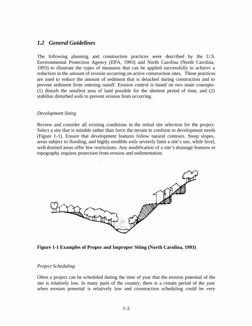


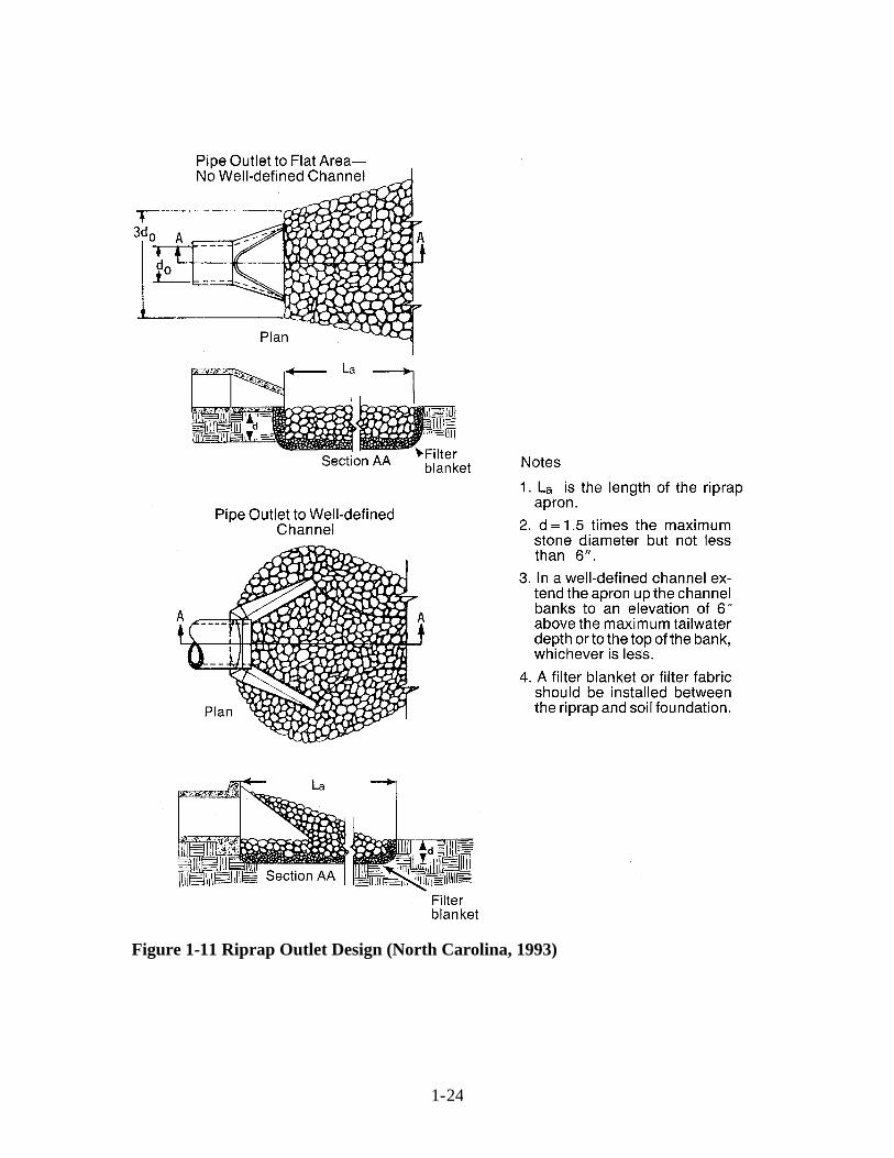


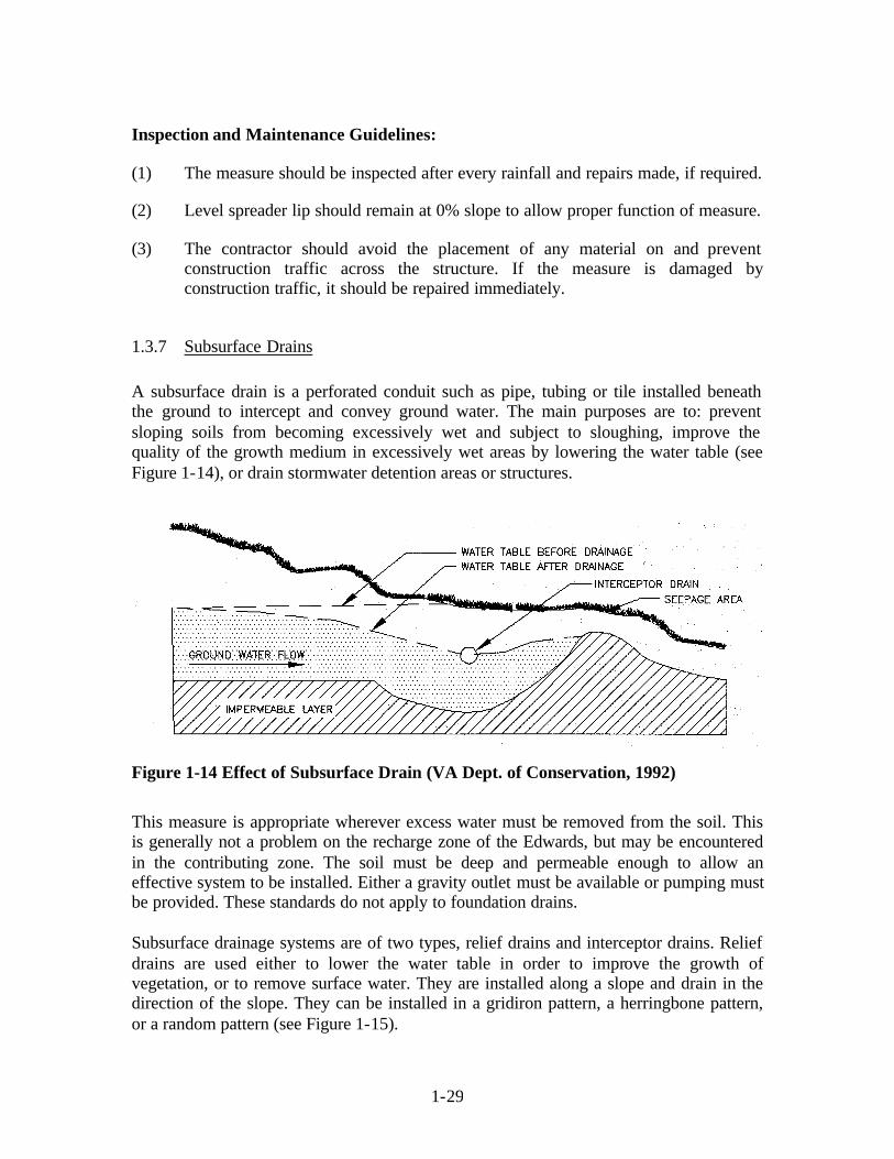


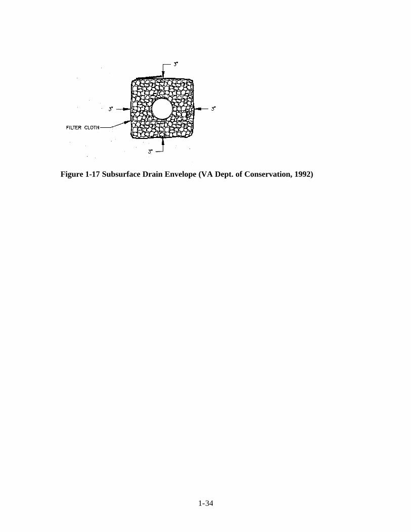


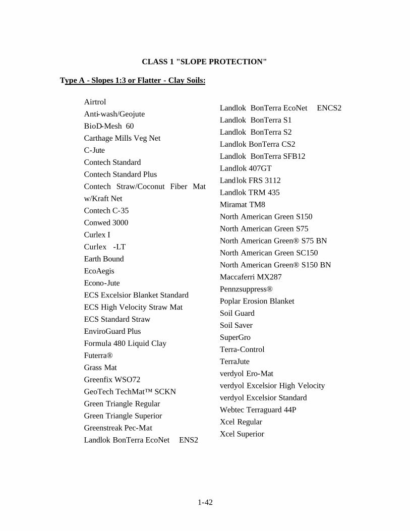


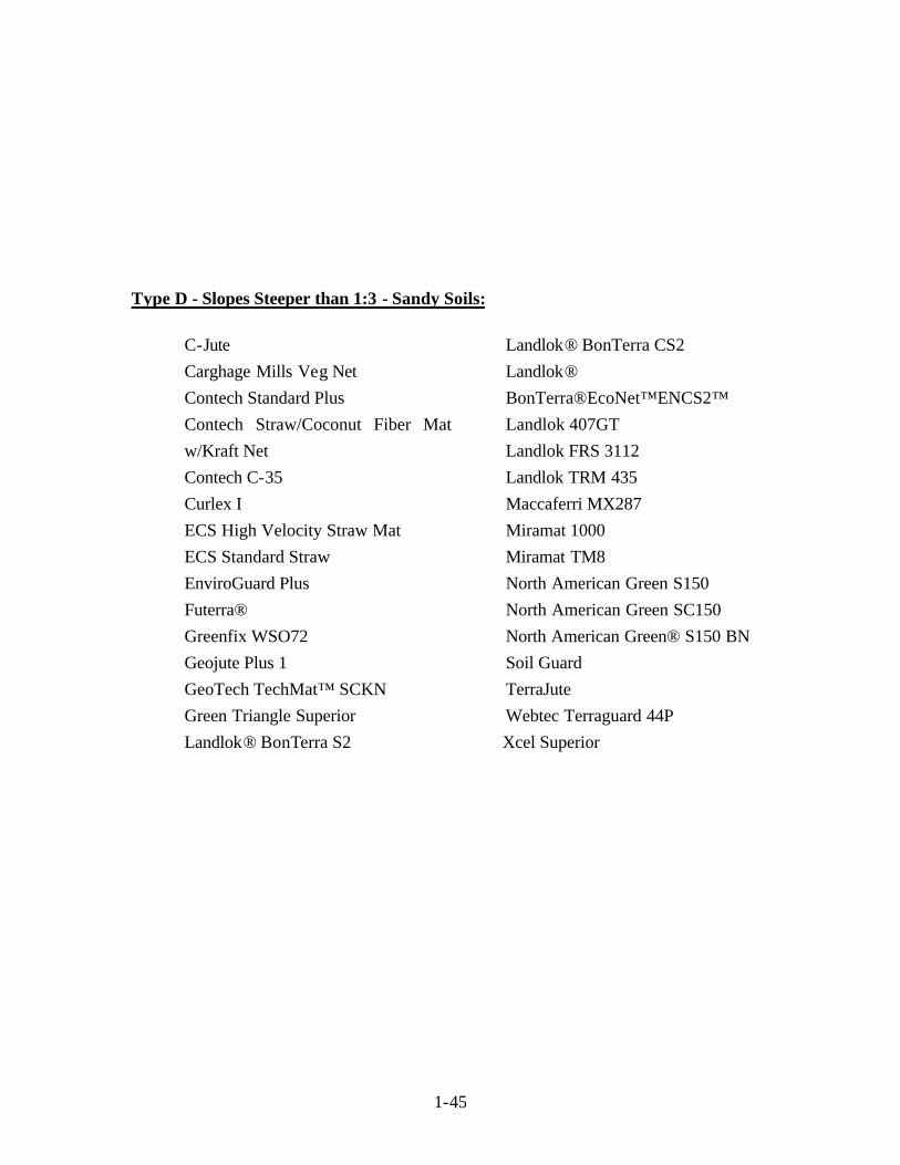
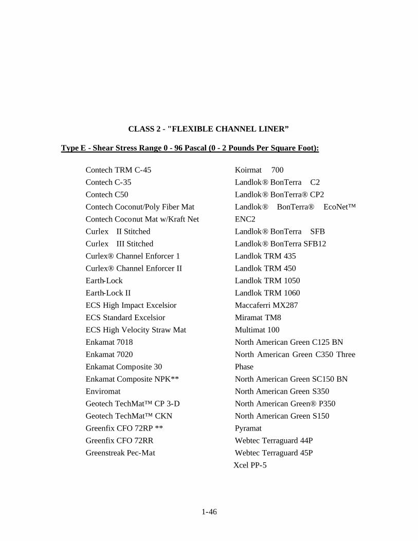
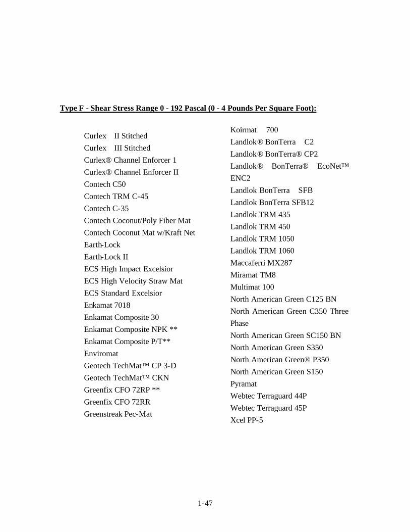


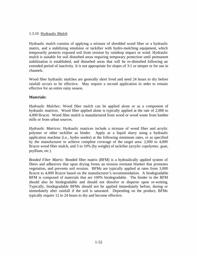


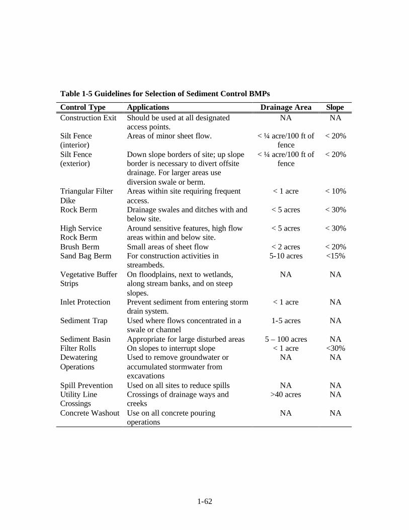
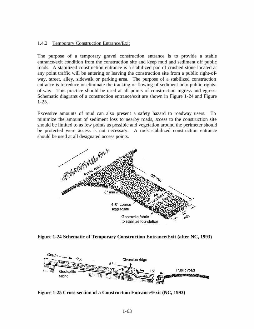

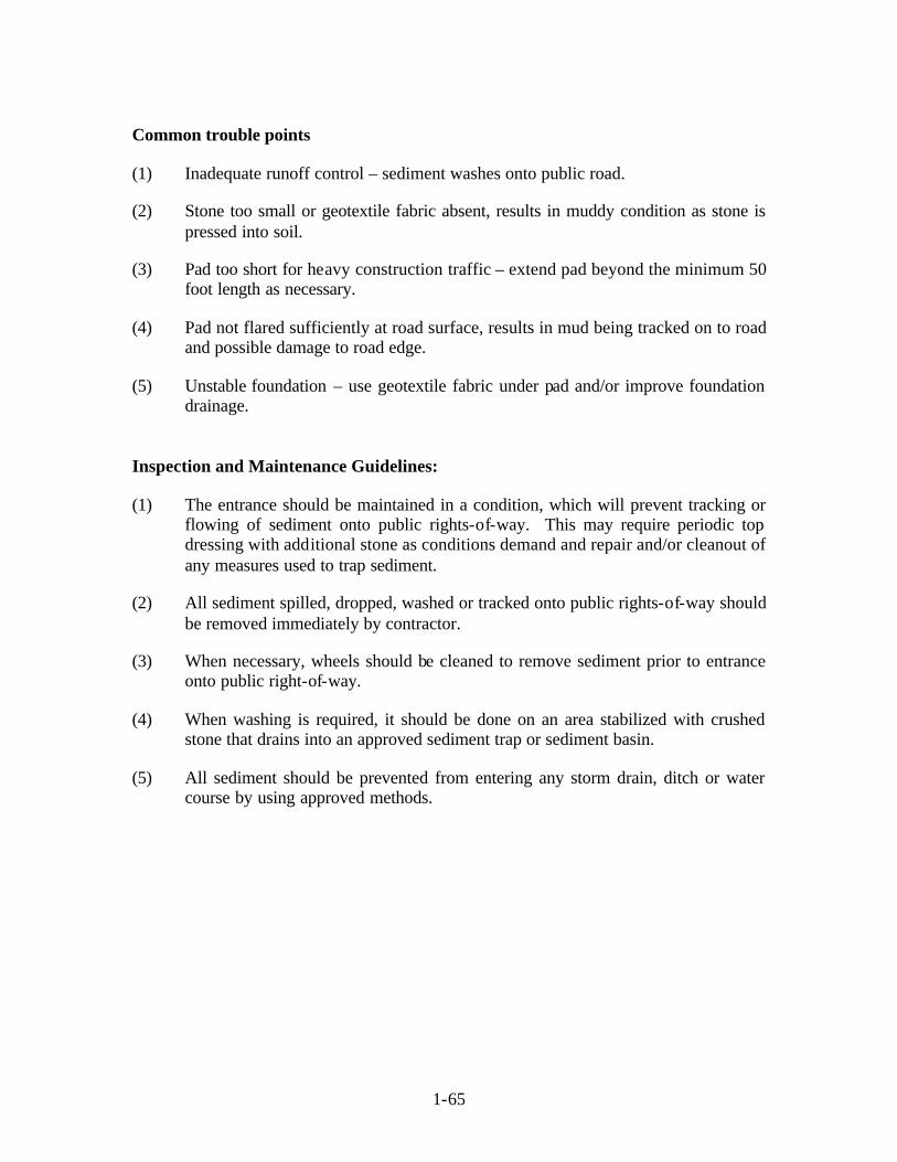


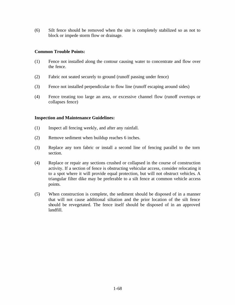


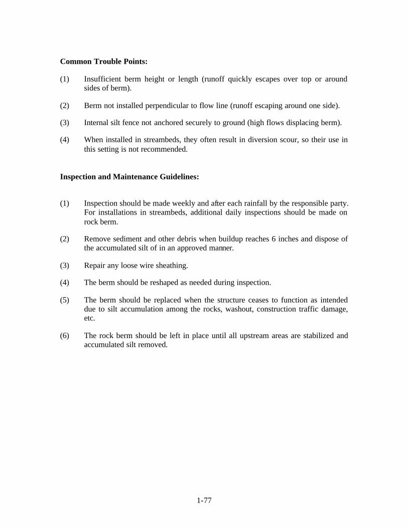


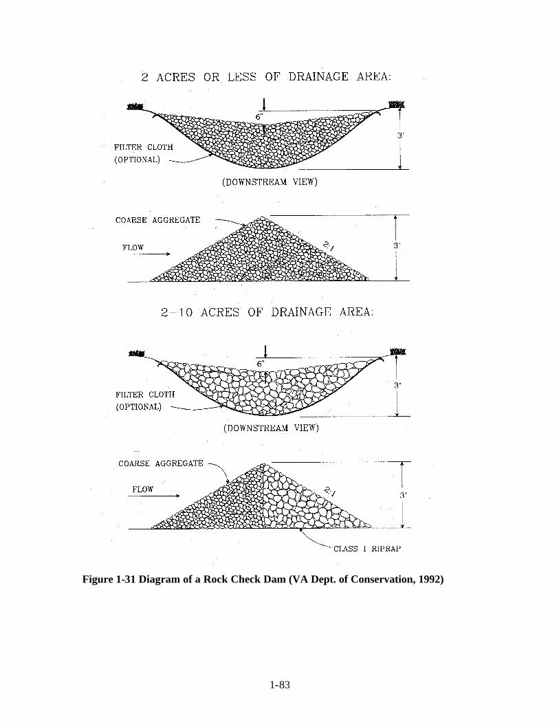


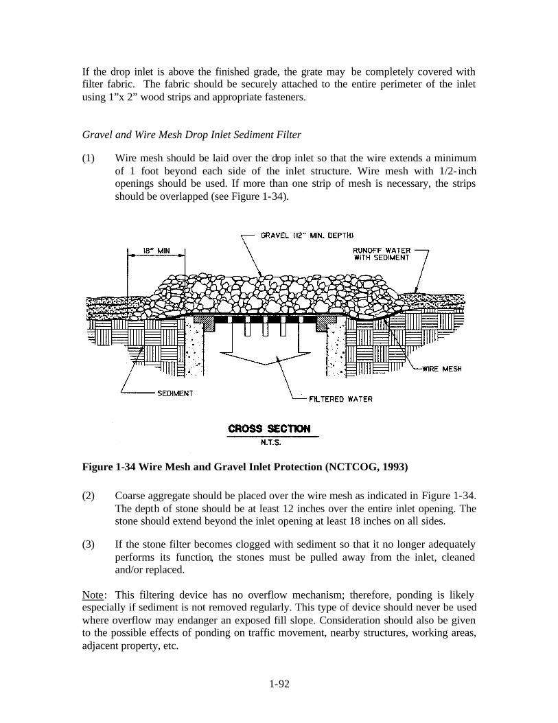

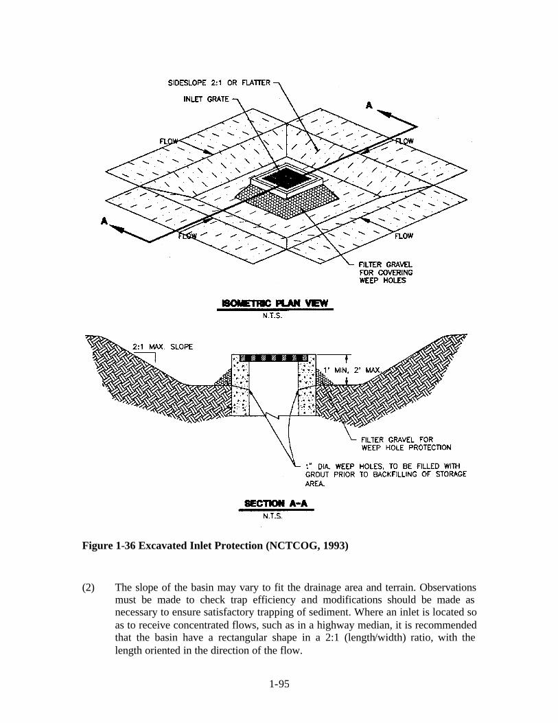
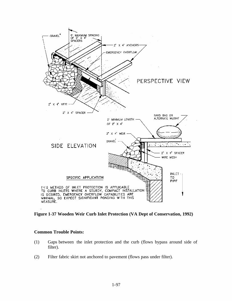


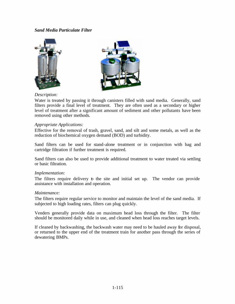
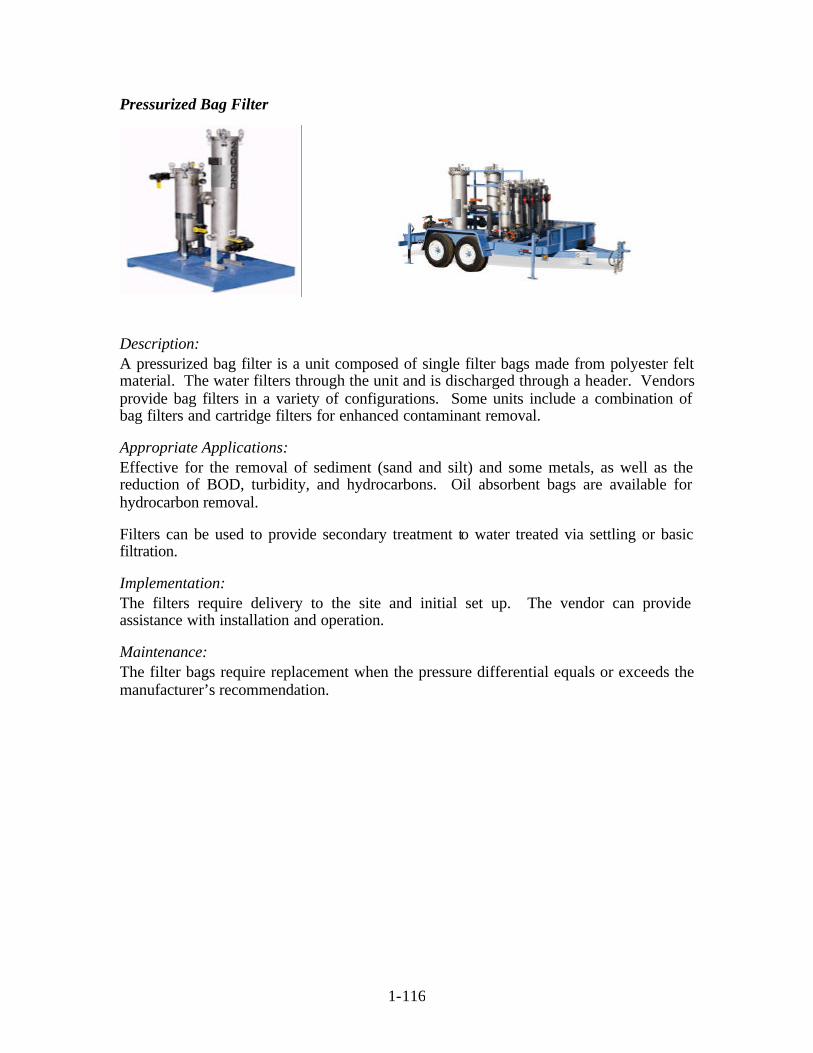


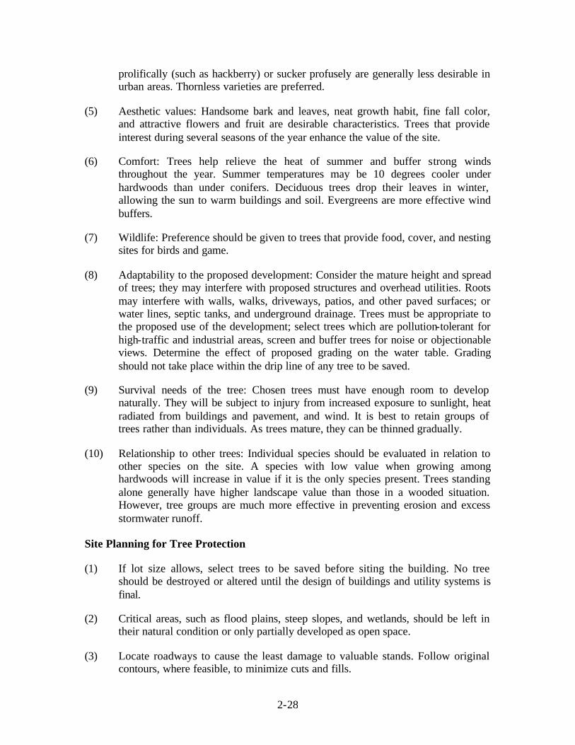


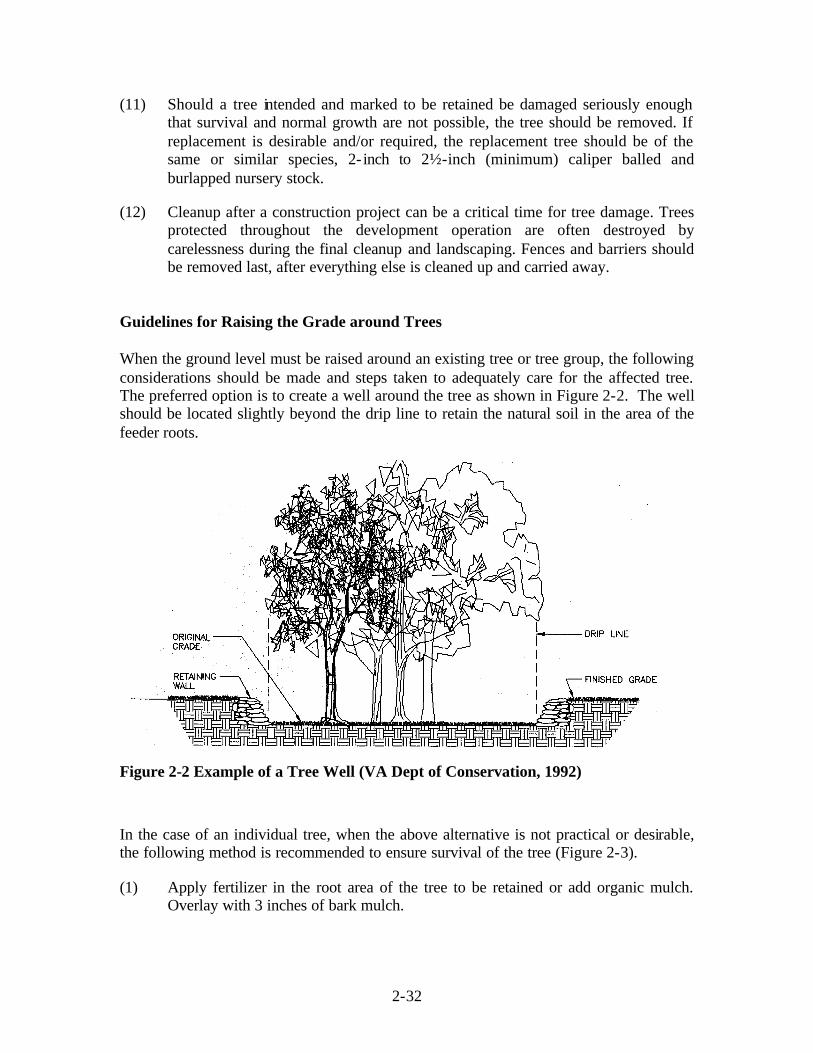


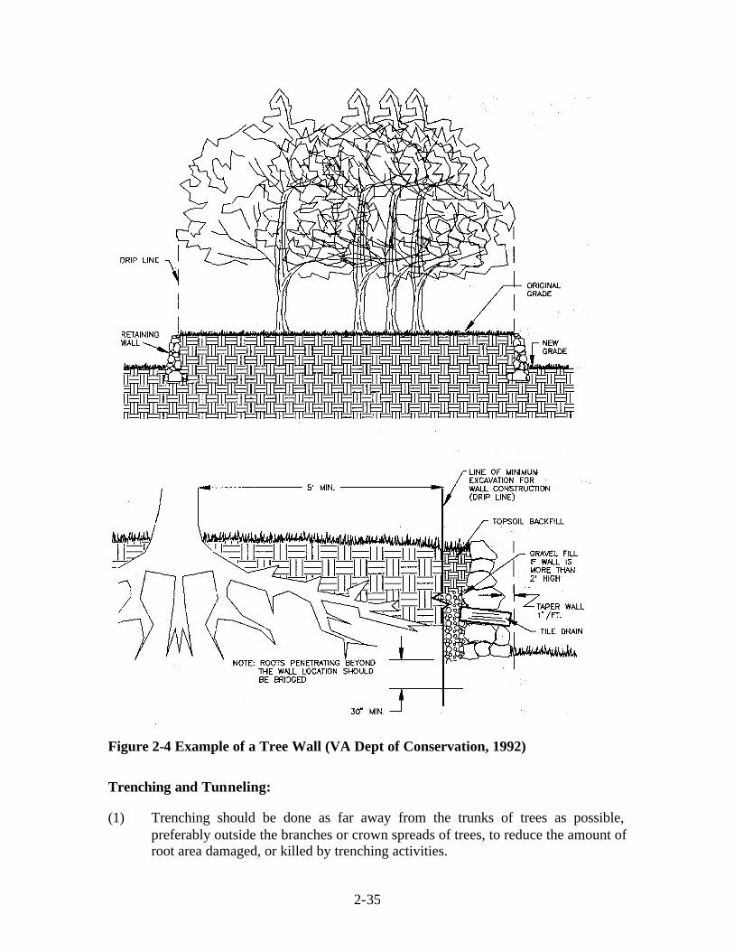


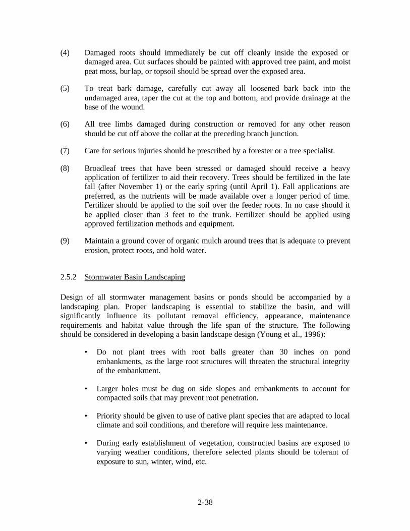


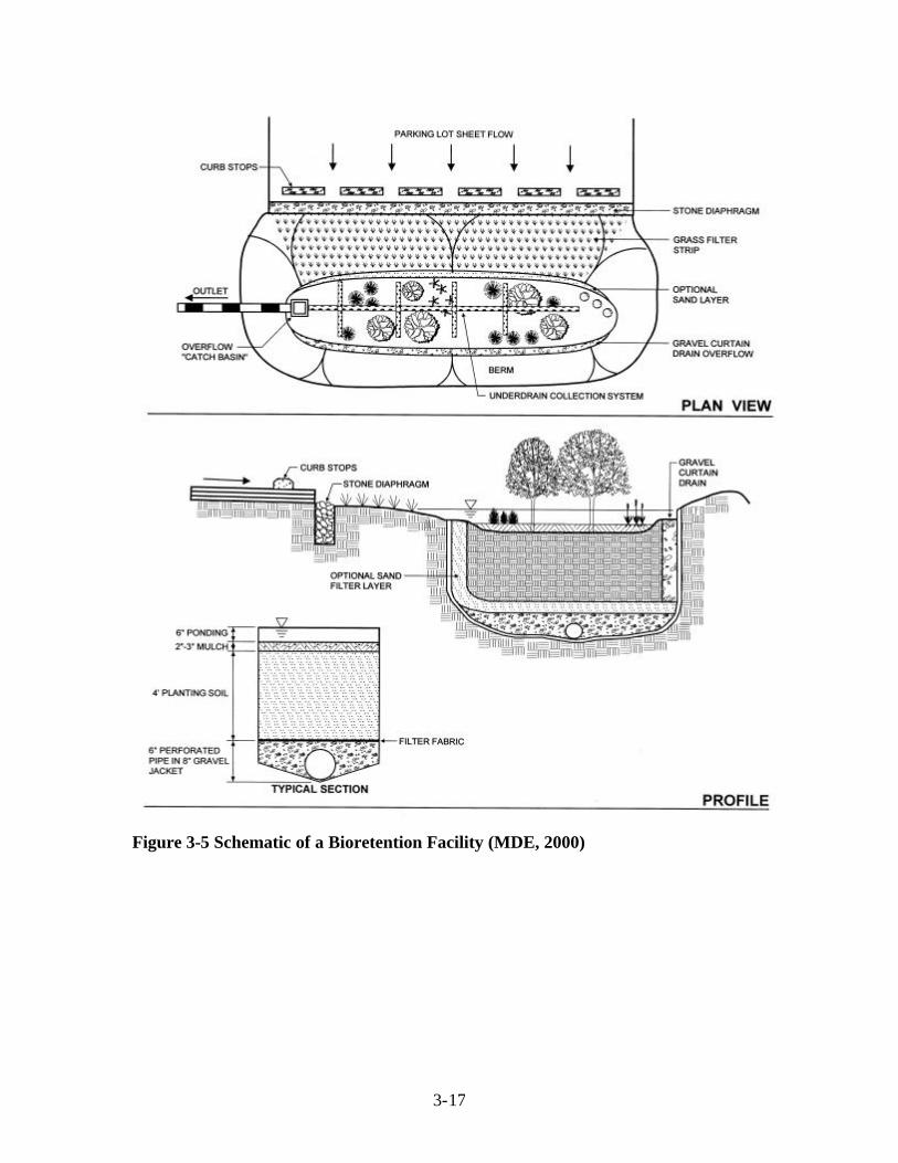


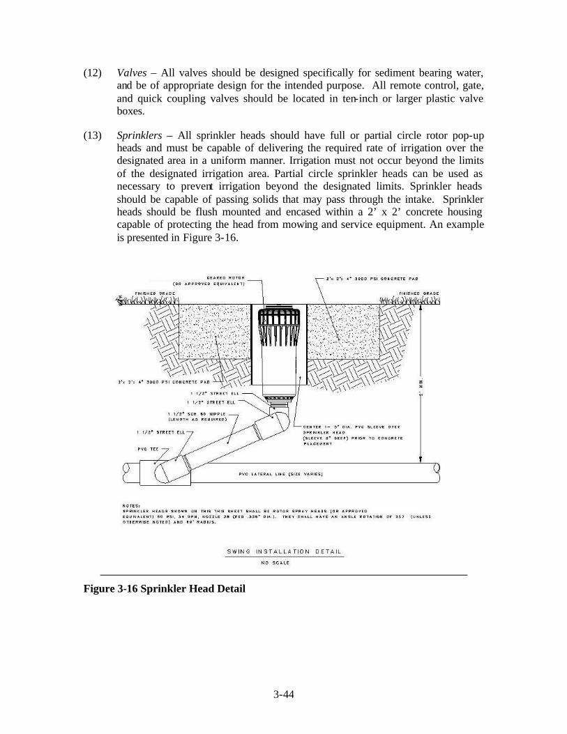


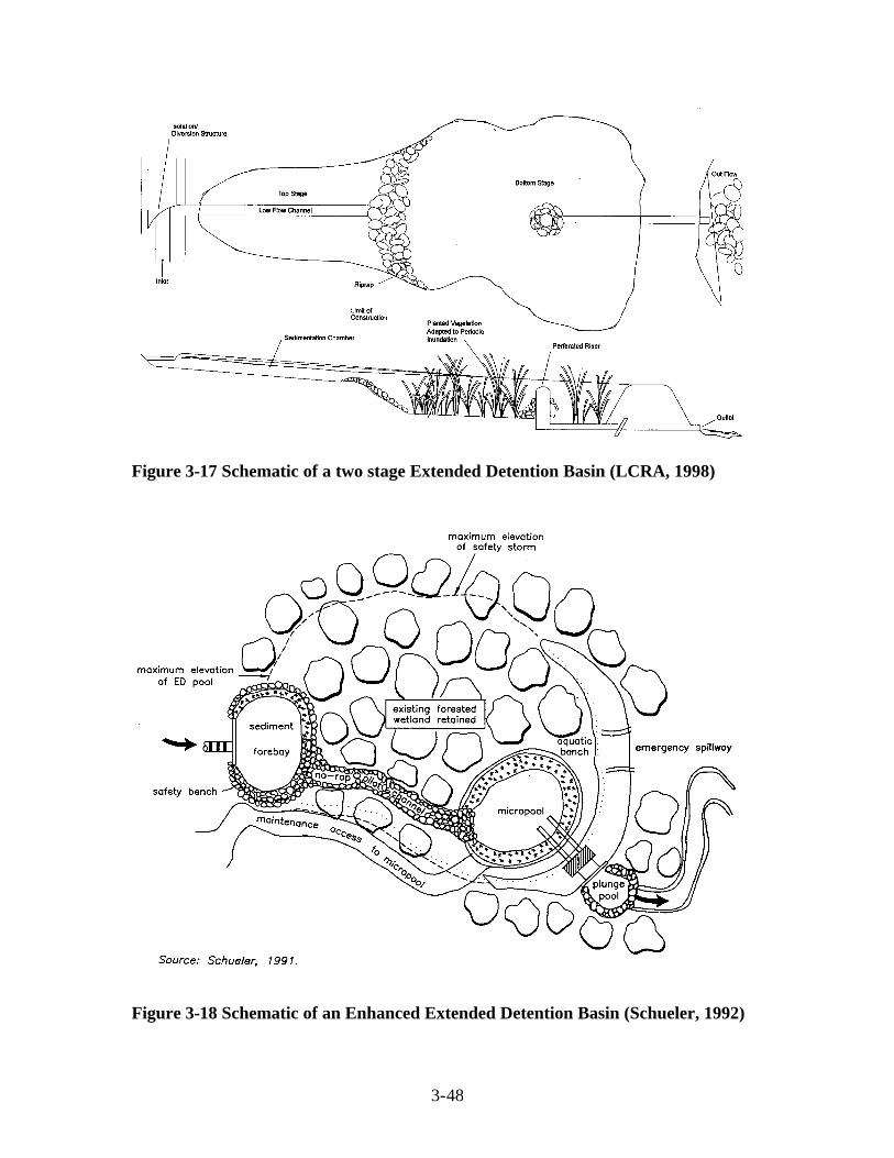


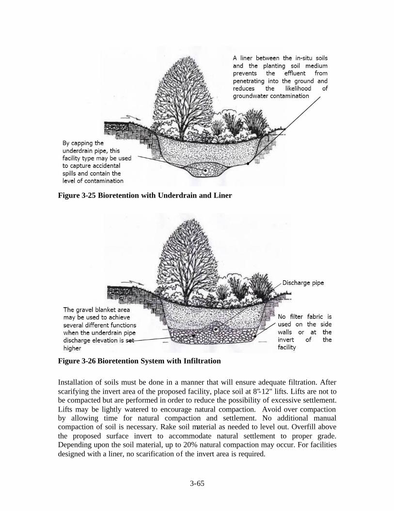


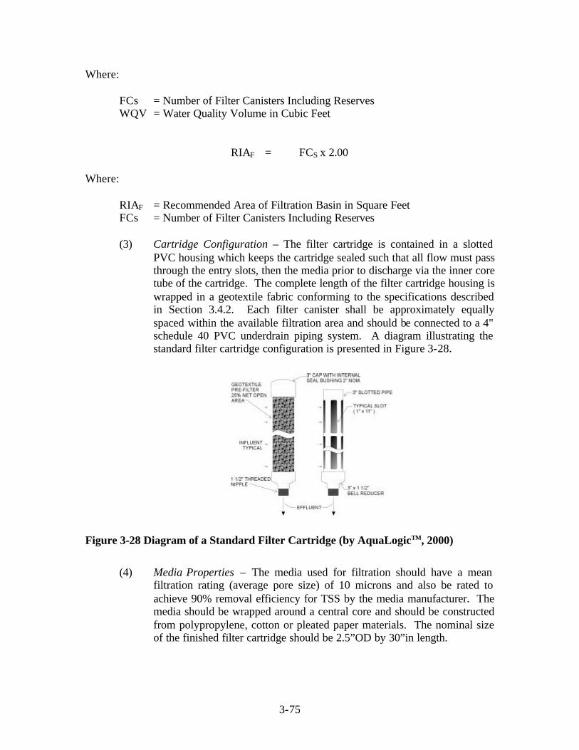

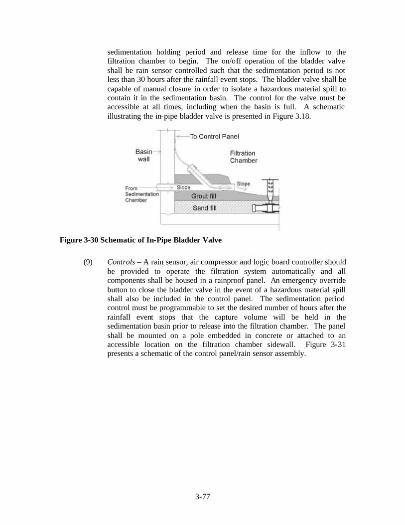
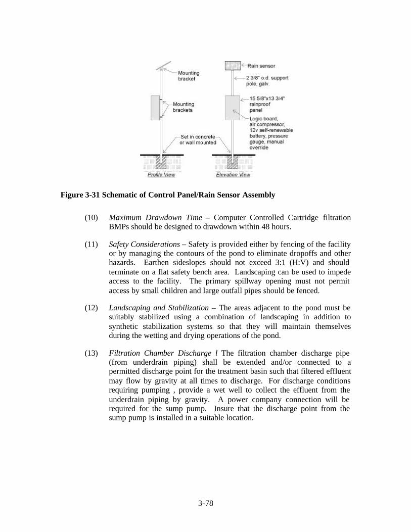


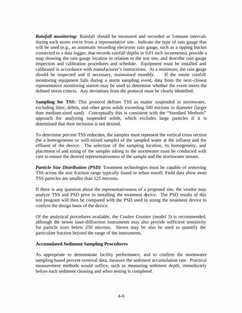


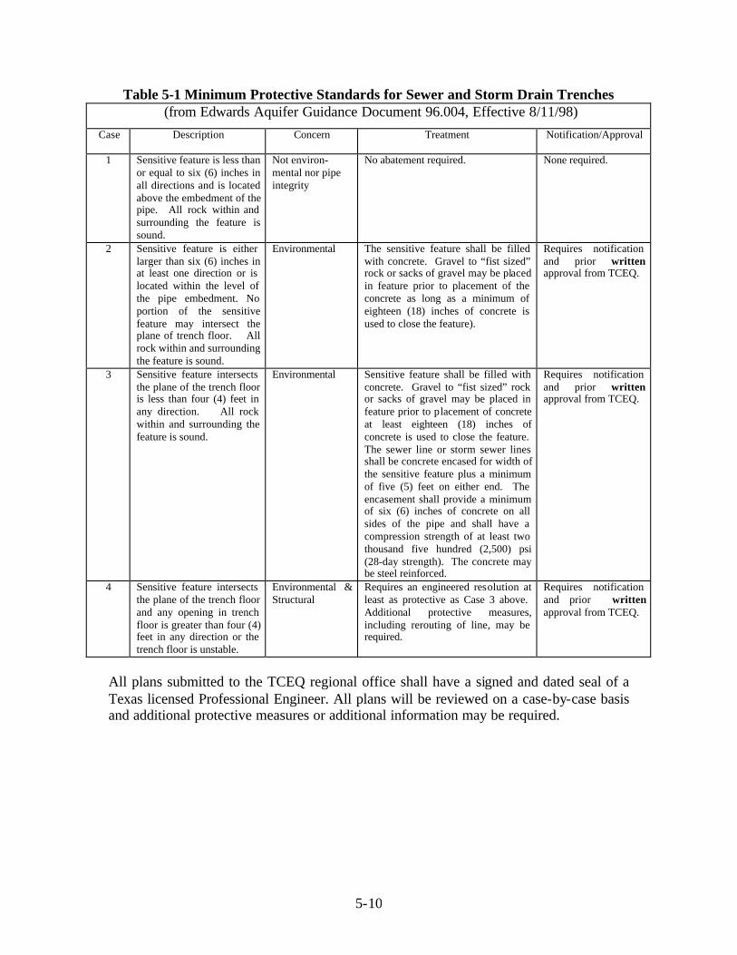


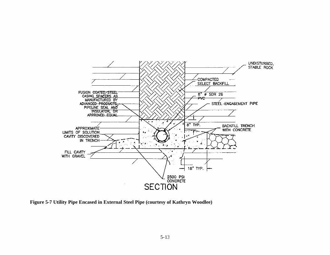
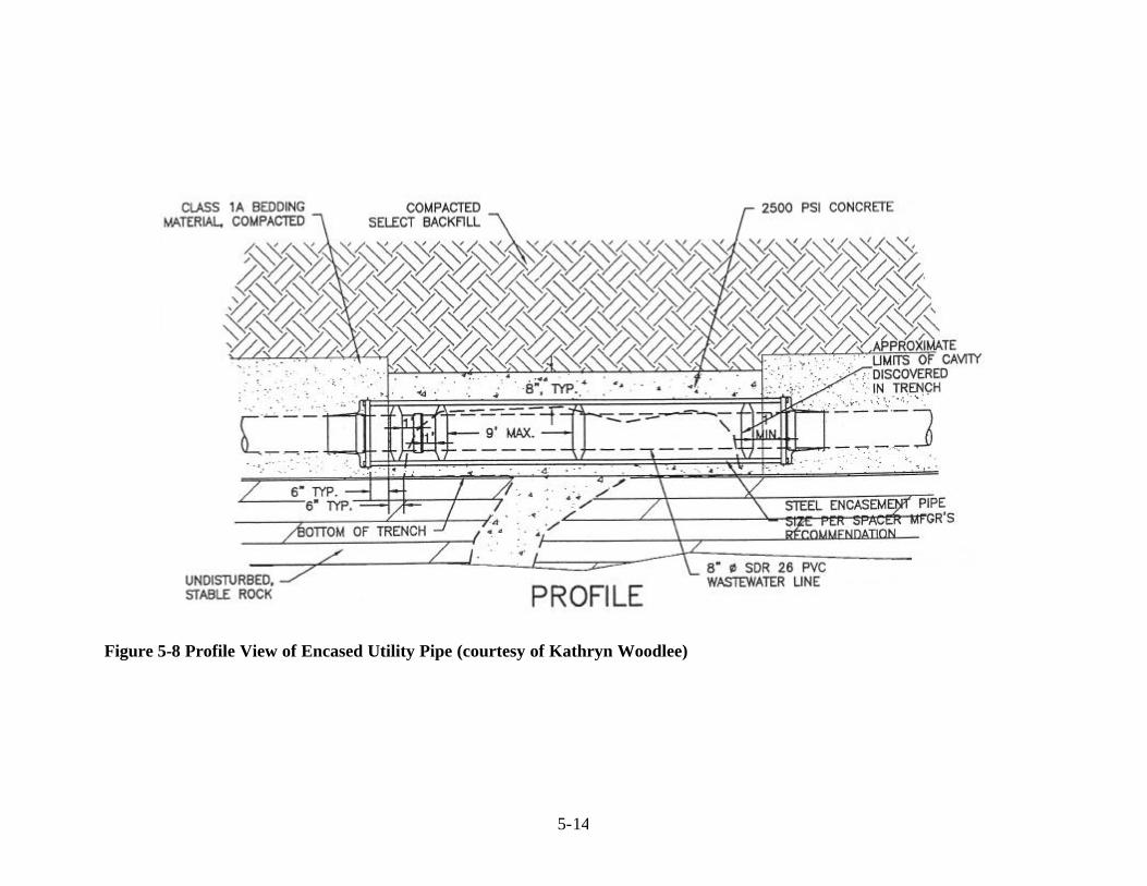


![[PPT]Vulernability map of the Edwards Aquifer - University of … · Web viewVulnerability map of the Edwards Aquifer Aquifer DRASTIC INDEX 84 - 90 90 - 978 97 - 104 104 – 111 111](https://static.documents.pub/doc/80x56/5aebf7d37f8b9ab24d8f7734/pptvulernability-map-of-the-edwards-aquifer-university-of-viewvulnerability.jpg)


