EE 489 Telecommunication Systems Engineering Introduction to Analog Telephony Concepts. Network Types. Trade-off Between Switching and Transmission Costs in Network Architecture. Trade-off Between Switching and Transmission Costs in Network Architecture. Network Types. - PowerPoint PPT Presentation
58
1 EE489 – Telecommunication Systems Engineering –University of Alberta, Dept. of Electrical and Computer Engineering EE 489 EE 489 Telecommunication Systems Engineering Telecommunication Systems Engineering Introduction to Analog Telephony Concepts Introduction to Analog Telephony Concepts
Transcript
1
EE489 – Telecommunication Systems Engineering –University of Alberta, Dept. of Electrical and Computer Engineering
EE 489EE 489Telecommunication Systems EngineeringTelecommunication Systems Engineering
Introduction to Analog Telephony ConceptsIntroduction to Analog Telephony Concepts
2
EE489 – Telecommunication Systems Engineering –University of Alberta, Dept. of Electrical and Computer Engineering
Network TypesNetwork Types
3
EE489 – Telecommunication Systems Engineering –University of Alberta, Dept. of Electrical and Computer Engineering
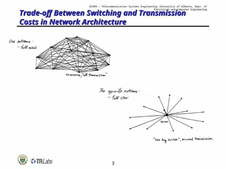
Trade-off Between Switching and Trade-off Between Switching and Transmission Costs in Network ArchitectureTransmission Costs in Network Architecture
4
EE489 – Telecommunication Systems Engineering –University of Alberta, Dept. of Electrical and Computer Engineering
Trade-off Between Switching and Trade-off Between Switching and Transmission Costs in Network ArchitectureTransmission Costs in Network Architecture
5
EE489 – Telecommunication Systems Engineering –University of Alberta, Dept. of Electrical and Computer Engineering
Network TypesNetwork Types
6
EE489 – Telecommunication Systems Engineering –University of Alberta, Dept. of Electrical and Computer Engineering
Concept of a “Homing Plan”Concept of a “Homing Plan”
7
EE489 – Telecommunication Systems Engineering –University of Alberta, Dept. of Electrical and Computer Engineering
PSTN HierarchyPSTN Hierarchy
Local Exchanges, orCentral Offices (C.O.’s)
Primary SwitchingCentres
Regional Exchanges
National Exchanges
International Exchanges
Also connected to submarine cables and
satellite links.
8
EE489 – Telecommunication Systems Engineering –University of Alberta, Dept. of Electrical and Computer Engineering
World Numbering PlanWorld Numbering Plan
• World is divided into zones, with each zone assigned a single digit zone codezone code.
• Each country within a zone is assigned a country codecountry code (usually 2-3 digits).– 1st digit is the country’s zone code.
• Regions or “numbering plan areasnumbering plan areas” (NPAs)within countries are assigned a 1-4 digit “area codearea code” or “routing coderouting code”.– NPA size and shape driven by numerous factors:
• Size and shape• Present and future numbering capacity• Political boundaries• Population demographics
• Local exchanges are assigned codes (3 digits in N.A.), followed by several digits assigned to each phone (4 digits in N.A.)
9
EE489 – Telecommunication Systems Engineering –University of Alberta, Dept. of Electrical and Computer Engineering
World Numbering Plan (2)World Numbering Plan (2)
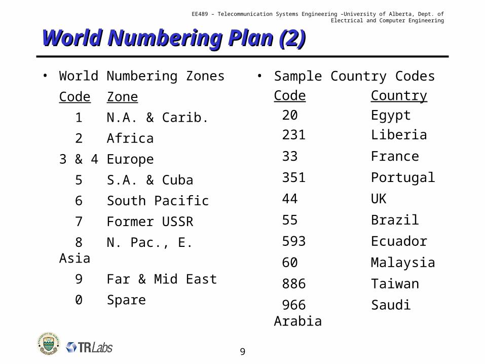
• World Numbering Zones
Code Zone
1 N.A. & Carib.
2 Africa
3 & 4 Europe
5 S.A. & Cuba
6 South Pacific
7 Former USSR
8 N. Pac., E. Asia
9 Far & Mid East
0 Spare
• Sample Country CodesCode Country
20 Egypt
231 Liberia
33 France
351 Portugal
44 UK
55 Brazil
593 Ecuador
60 Malaysia
886 Taiwan
966 Saudi Arabia
10
EE489 – Telecommunication Systems Engineering –University of Alberta, Dept. of Electrical and Computer Engineering
Network ArchitectureNetwork Architecture
Customer terminals 20%
Outside plant, cables 29%
Switching equipment 25%
Multiplexing and Transmission equipment 15%
Buildings, land, other 11%
11
EE489 – Telecommunication Systems Engineering –University of Alberta, Dept. of Electrical and Computer Engineering
Telephone SystemTelephone System
• Early telephone system– Powered by self-contained local battery– Ringing created by cranking generator
• Today’s telephone system– Powered through the line by battery at the central office (-
48V)– Circuit is closed when handset is lifted from the cradle (“off off
hookhook”)
• Transmitter – carbon granule microphone– Air pressure of sound waves impact on diaphragm, varying
pressure on carbon granules– Resistance of electrical current passing through carbon
granules varies the current (analog)
• Receiver– Varying electrical current passing through windings on
magnet, moves a diaphragm. Same as in a music loudspeaker.
12
EE489 – Telecommunication Systems Engineering –University of Alberta, Dept. of Electrical and Computer Engineering
Telephone System (2)Telephone System (2)
• “PSTNPSTN”, or “POTSPOTS” simplified circuit model of any connection:
coil (ZB)
central battery
speech current
The coil is a “transmission bridge transmission bridge coilcoil” with a high impedance (ZB) preventing the speech current from shorting out at the central battery.
13
EE489 – Telecommunication Systems Engineering –University of Alberta, Dept. of Electrical and Computer Engineering
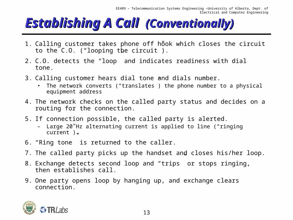
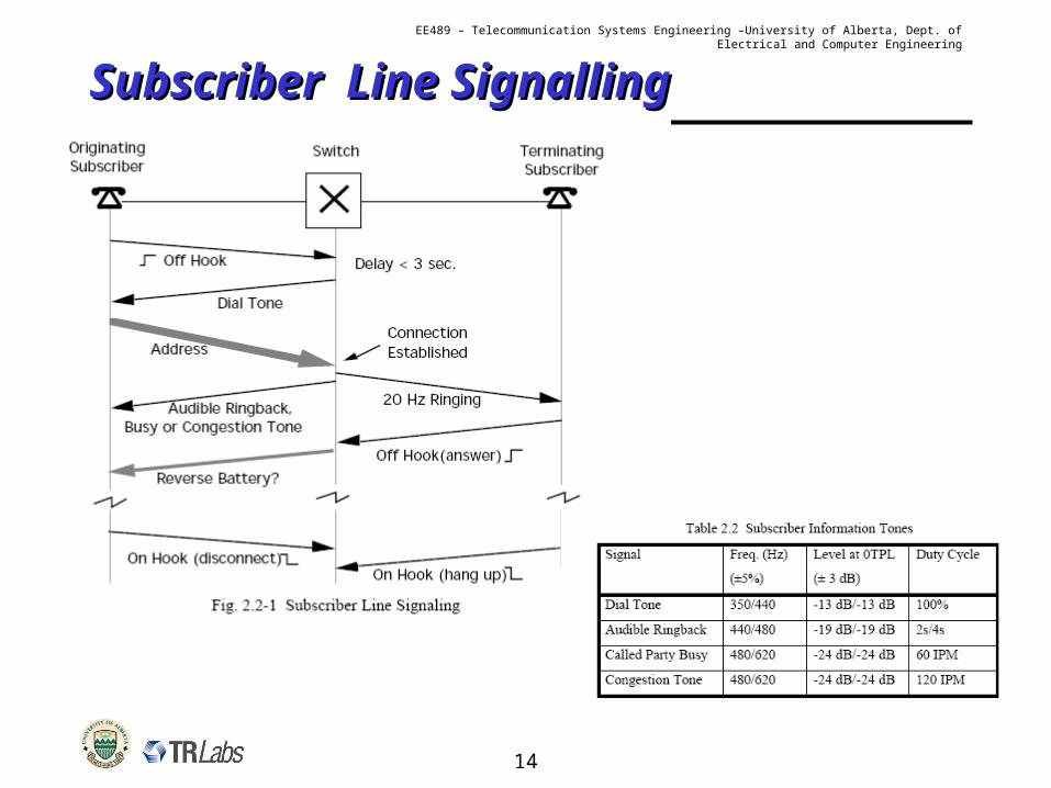
Establishing A Call Establishing A Call (Conventionally)(Conventionally)1. Calling customer takes phone off hook which closes the circuit to
the C.O. (“looping the circuit”).
2. C.O. detects the “loop” and indicates readiness with dial tone.
3. Calling customer hears dial tone and dials number.• The network converts (“translates”) the phone number to a physical
equipment address
4. The network checks on the called party status and decides on a routing for the connection.
5. If connection possible, the called party is alerted.– Large 20 Hz alternating current is applied to line (“ringing current”).
6. “Ring tone” is returned to the caller.
7. The called party picks up the handset and closes his/her loop.
8. Exchange detects second loop and “trips” or stops ringing, then establishes call.
9. One party opens loop by hanging up, and exchange clears connection.
14
EE489 – Telecommunication Systems Engineering –University of Alberta, Dept. of Electrical and Computer Engineering
Subscriber Line SignallingSubscriber Line Signalling
15
EE489 – Telecommunication Systems Engineering –University of Alberta, Dept. of Electrical and Computer Engineering
Loop and Disconnect SignallingLoop and Disconnect Signalling
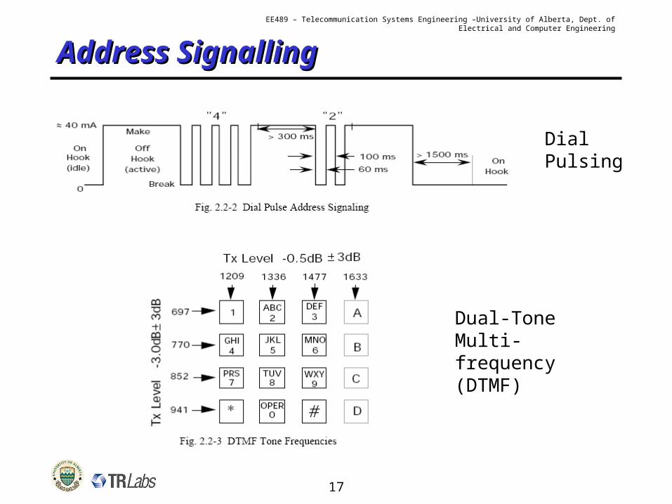
“pulse diallingpulse dialling” :
• Line is rapidly disconnected and reconnected in sequence with one pulse for digit value “1”, two pulses for digit value “2”, etc.
• Each pulse lasts 0.1 second.
• Inter-digit pause (IDP) must be >0.5 second.– If not, current digit may combine with previous digit.
• Ten digit phone number typically takes 6-15 seconds total.
• This is the kind of signalling old “rotary dial” phones produced.
16
EE489 – Telecommunication Systems Engineering –University of Alberta, Dept. of Electrical and Computer Engineering
DTMF signallingDTMF signalling” or “tone signallingtone signalling”.
• Faster than pulse dialling (1-2 seconds for ten digit number).– Reduces call set-up time.
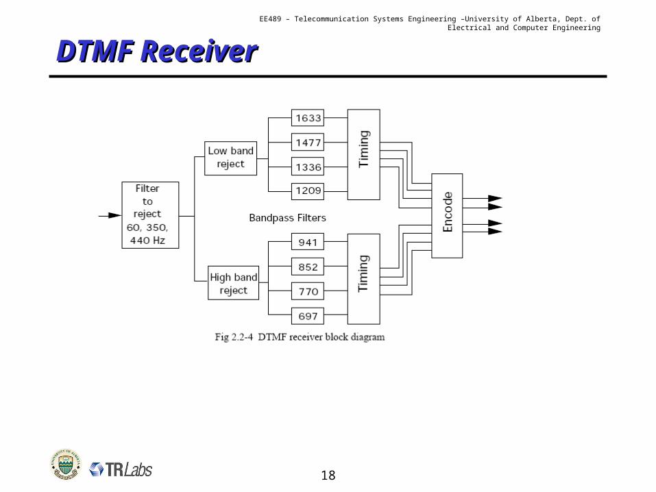
• Each digit produced by combination of 2 pure frequency tones.– Reduces chances of error or interference.
1208 Hz 1336 Hz 1477 Hz 1633 Hz
697 Hz 1 2 3 spare
770 Hz 4 5 6 spare
852 Hz 7 8 9 spare
941 Hz * 0 # spare
High Frequency Tone
Low
Fre
quen
cy T
one
17
EE489 – Telecommunication Systems Engineering –University of Alberta, Dept. of Electrical and Computer Engineering
Address SignallingAddress Signalling
Dial Pulsing
Dual-Tone Multi-frequency (DTMF)
18
EE489 – Telecommunication Systems Engineering –University of Alberta, Dept. of Electrical and Computer Engineering
DTMF ReceiverDTMF Receiver
19
EE489 – Telecommunication Systems Engineering –University of Alberta, Dept. of Electrical and Computer Engineering
The Concept and Implications of The Concept and Implications of “two-wire” (2W) to “four-wire” (4W) “two-wire” (2W) to “four-wire” (4W) conversionconversion
Or…why your phone only needs one twisted pair and why you sometimes hear an echo
20
EE489 – Telecommunication Systems Engineering –University of Alberta, Dept. of Electrical and Computer Engineering
2-W to 4-W Conversion2-W to 4-W Conversion
• For short distances, two-way communication is possible on a single pair of wires (bi-directional transmission).
• Problems occur however when amplification (in past) or digital regeneration (nowadays) is needed.– Amplifiers or regenerators in the network are uni-directional.
A Hybrid TransformerHybrid Transformer is used to convert a 2-wire circuit at the phone/terminal end to a 4-wire system in the switching network:
Balance Network (ZB)
2-W Line (ZLine)4-wire portion
Send Amplifier
Receive Amplifier
21
EE489 – Telecommunication Systems Engineering –University of Alberta, Dept. of Electrical and Computer Engineering
2-W to 4-W Conversion (2)2-W to 4-W Conversion (2)
2-wires 2-wiresHybrid Hybrid
Amplifier or Regenerator
2-wires 2-wires
receivetransmit
Amplifier
2-wires 2-wires
receive transmit
22
EE489 – Telecommunication Systems Engineering –University of Alberta, Dept. of Electrical and Computer Engineering
2-Wire to 4-Wire Conversion2-Wire to 4-Wire Conversion
•Any telephone call undergoes 2W-4W conversions:
- from the phone (4W) to the subscriber line (2W)
- from the subscriber line (2W) to the network interface (4W)
Overall structure of any phone connection
“2W”
“2W”
“4W”
“4W”
“4W”
23
EE489 – Telecommunication Systems Engineering –University of Alberta, Dept. of Electrical and Computer Engineering
2-W to 4-W Conversion (3)2-W to 4-W Conversion (3)
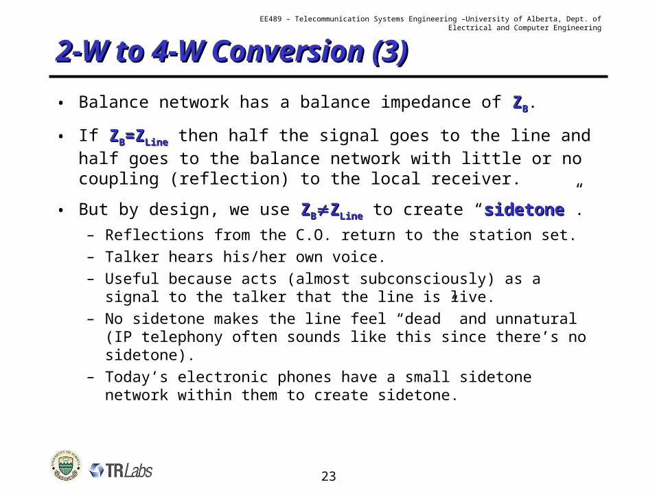
• Balance network has a balance impedance of ZZBB.
• If ZZBB=Z=ZLineLine then half the signal goes to the line and half goes to the balance network with little or no coupling (reflection) to the local receiver.
• But by design, we use ZZBBZZLineLine to create “sidetonesidetone”.– Reflections from the C.O. return to the station set.– Talker hears his/her own voice.– Useful because acts (almost subconsciously) as a signal to
the talker that the line is live.– No sidetone makes the line feel “dead” and unnatural (IP
telephony often sounds like this since there’s no sidetone).– Today’s electronic phones have a small sidetone network
within them to create sidetone.
24
EE489 – Telecommunication Systems Engineering –University of Alberta, Dept. of Electrical and Computer Engineering
2W to 4W conversion: The “Hybrid Coupler” 2W to 4W conversion: The “Hybrid Coupler”
CircuitCircuit
25
EE489 – Telecommunication Systems Engineering –University of Alberta, Dept. of Electrical and Computer Engineering
2W to 4W conversion: The “Hybrid Coupler” 2W to 4W conversion: The “Hybrid Coupler”
CircuitCircuit
26
EE489 – Telecommunication Systems Engineering –University of Alberta, Dept. of Electrical and Computer Engineering
EE489 – Telecommunication Systems Engineering –University of Alberta, Dept. of Electrical and Computer Engineering
Three Main Design Three Main Design Goals/MethodsGoals/Methods• (A) (D.C.) Resistance Limit Requirement (A) (D.C.) Resistance Limit Requirement
– Keep total line resistance below a target level by choosing the appropriate wire gauges.
– Historically 1300 limit but now ~1700 .
• (B) (A.C.) Attenuation Limit Requirement(B) (A.C.) Attenuation Limit Requirement– Keep total signal loss below a target maximum level.– North America usually uses 8 dB maximum loss at 1000 Hz.– Elsewhere usually uses 7 dB maximum loss at 800 Hz.
• ““Uni-Gauge” Design MethodUni-Gauge” Design Method– In principle could mix and match wire gauges in loop makeup
to satisfy (A) and (B) at minimum cost of the copper used.– Actual practice has been to keep to a single size wire (often
26 gauge) as much as possible (better economically) and add battery boost, range extenders, amplifiers, or “load coils” as needed.
32
EE489 – Telecommunication Systems Engineering –University of Alberta, Dept. of Electrical and Computer Engineering
More on Resistance DesignMore on Resistance Design
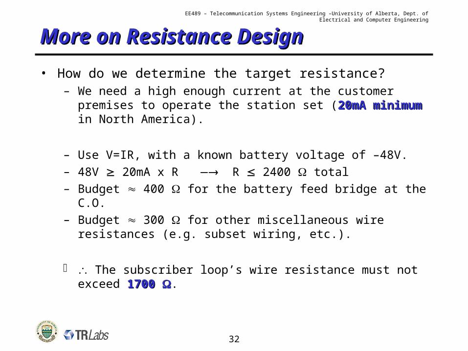
• How do we determine the target resistance?– We need a high enough current at the customer premises
to operate the station set (20mA minimum20mA minimum in North America).
– Use V=IR, with a known battery voltage of –48V.– 48V 20mA x R R 2400 total– Budget 400 for the battery feed bridge at the C.O.– Budget 300 for other miscellaneous wire resistances
(e.g. subset wiring, etc.).
The subscriber loop’s wire resistance must not exceed 1700 1700 .
33
EE489 – Telecommunication Systems Engineering –University of Alberta, Dept. of Electrical and Computer Engineering
American Wire Gauge (AWG) American Wire Gauge (AWG) DataData
•N.B.: Each change of 3 gauge numbers is a factor of 2 in wire area (cross section), this a factor of 2 in resistance / unit length
34
EE489 – Telecommunication Systems Engineering –University of Alberta, Dept. of Electrical and Computer Engineering
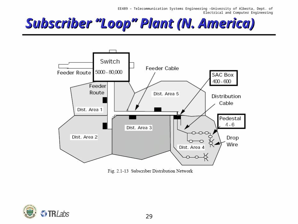
Subscriber “Loop” PlantSubscriber “Loop” Plant
35
EE489 – Telecommunication Systems Engineering –University of Alberta, Dept. of Electrical and Computer Engineering
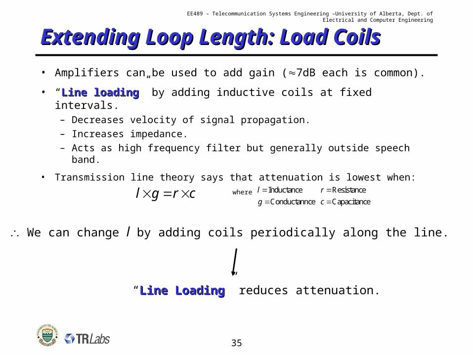
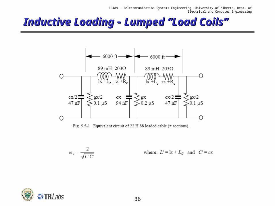
Extending Loop Length: Load Extending Loop Length: Load CoilsCoils• Amplifiers can be used to add gain (7dB each is common).
• “Line loadingLine loading” by adding inductive coils at fixed intervals.– Decreases velocity of signal propagation.– Increases impedance.– Acts as high frequency filter but generally outside speech
band.
• Transmission line theory says that attenuation is lowest when:l g r c where Inductancel
Conductannceg Resistancer Capacitancec
We can change l by adding coils periodically along the line.
“Line LoadingLine Loading” reduces attenuation.
36
EE489 – Telecommunication Systems Engineering –University of Alberta, Dept. of Electrical and Computer Engineering
EE489 – Telecommunication Systems Engineering –University of Alberta, Dept. of Electrical and Computer Engineering
Inductively Loaded Line Inductively Loaded Line Notation Notation Example #1: “19H8819H88” means 19 gauge wire loaded every 1830 m (H) with 88mH inductors.
Example #2: “26B6626B66” means 26 gauge wire loaded every 915 m (B) with 66mH inductors.
Some Cable Conductor Properties:
41
EE489 – Telecommunication Systems Engineering –University of Alberta, Dept. of Electrical and Computer Engineering
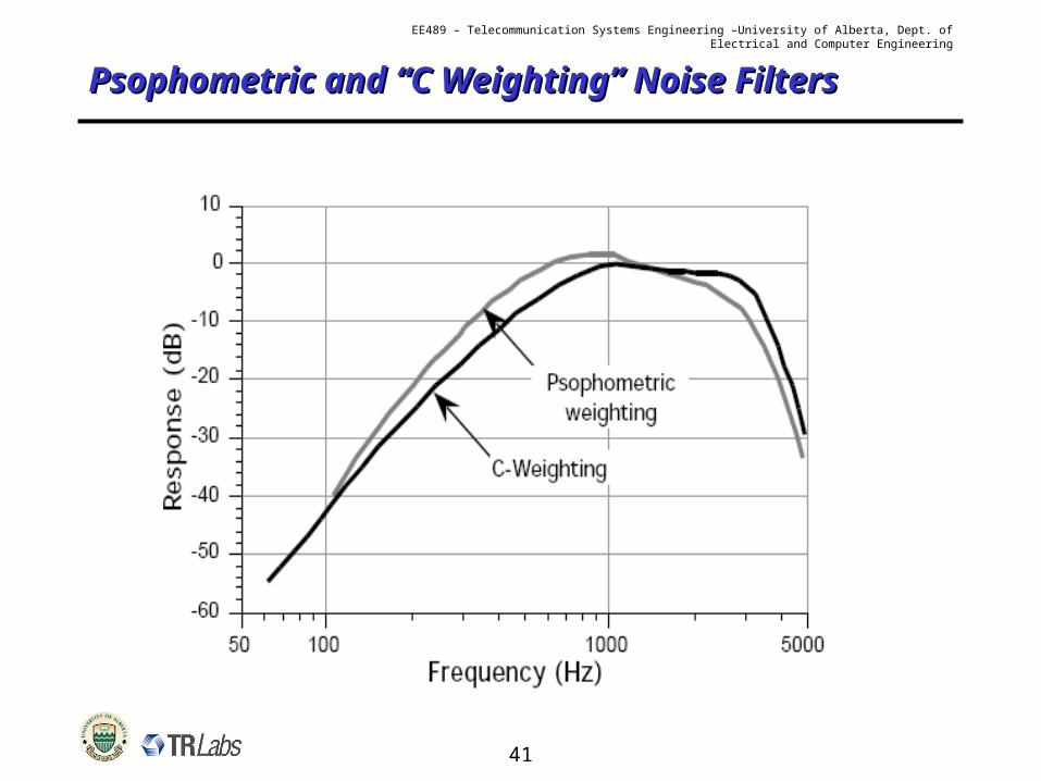
Psophometric and “C Weighting” Noise Psophometric and “C Weighting” Noise FiltersFilters
42
EE489 – Telecommunication Systems Engineering –University of Alberta, Dept. of Electrical and Computer Engineering
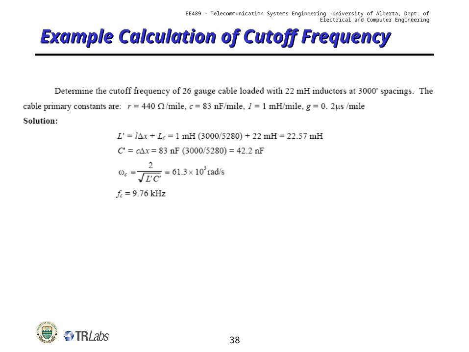
ExampleExample
43
EE489 – Telecommunication Systems Engineering –University of Alberta, Dept. of Electrical and Computer Engineering
Network Loss PlanningNetwork Loss Planning
• Received Volume Control– Subscribers must have a received signal level within an
appropriate range.– i.e. Not too loud and not to quiet.
• Stability or Oscillation Control: “Singing”– Manage reflections that can result if there’s a poor
mismatch of the 2-wire line impedance and the hybrid balance impedance.
– Singing can result.
• Talker Echo– Talker should not hear his/her own voice reflected back
(with a significant enough delay).
44
EE489 – Telecommunication Systems Engineering –University of Alberta, Dept. of Electrical and Computer Engineering
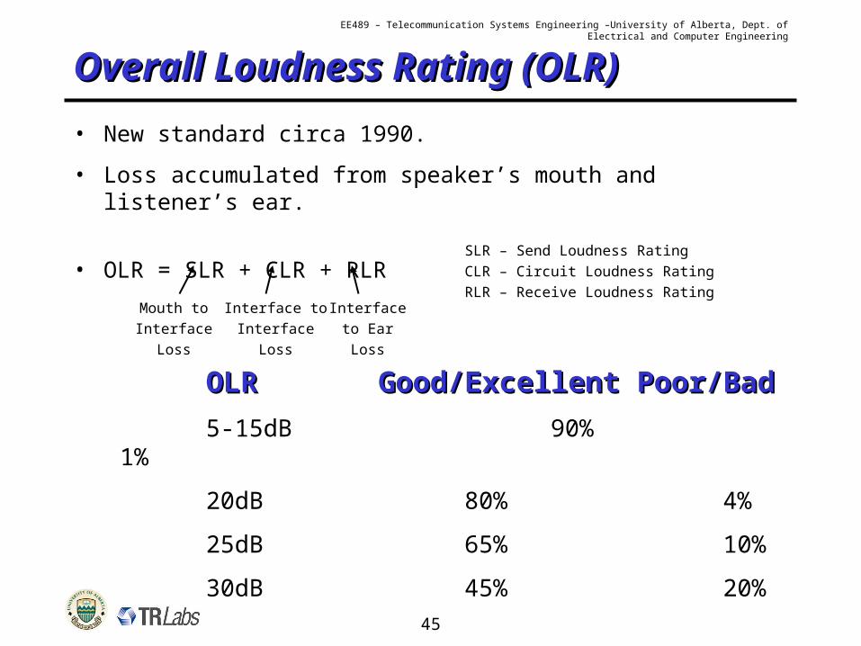
Volume ObjectivesVolume Objectives
• Reference Equivalent (RE) or Overall R. E. (ORE)– A measure of perceived loudness of the signal.– ITU in Geneva used group of telephone users to judge
loudness.– Measured by adjusting an attenuator in a simulated
network.– Rated “highest tolerable volume”, “preferred volume” and
“lowest tolerable volume”.– Results showed that attenuator settings of <6dB were too
loud and >21dB were too faint.
45
EE489 – Telecommunication Systems Engineering –University of Alberta, Dept. of Electrical and Computer Engineering
EE489 – Telecommunication Systems Engineering –University of Alberta, Dept. of Electrical and Computer Engineering
StabilityStability
• Long distance connections all have 2-W to 4-W to 2-W conversion (as do most local connections).
• If there’s a poor mismatch of the 2-W line impedance with the hybrid balance impedance, signal energy passes across the hybrid reflecting from one 4-W direction into the other.
2-wires 2-wiresHybrid Hybrid
Amplifier
2-wires 2-wires
receivetransmit
Amplifier
2-wires 2-wires
receive transmit
Reflection(ZB ZL)
47
EE489 – Telecommunication Systems Engineering –University of Alberta, Dept. of Electrical and Computer Engineering
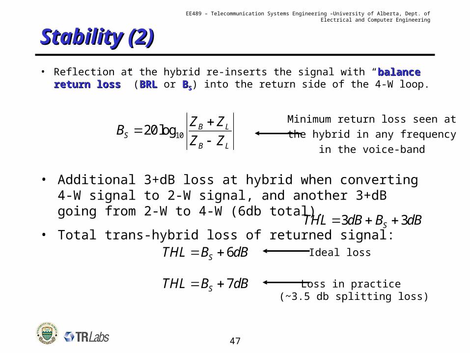
Stability (2)Stability (2)
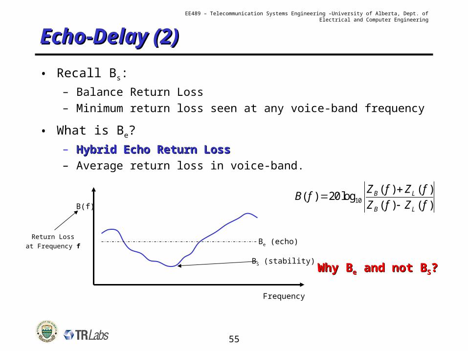
• Reflection at the hybrid re-inserts the signal with “balance balance return lossreturn loss” (BRLBRL or BBSS) into the return side of the 4-W loop.
1020log B LS
B L
Z ZB
Z Z
Minimum return loss seen atthe hybrid in any frequency
in the voice-band
• Additional 3+dB loss at hybrid when converting 4-W signal to 2-W signal, and another 3+dB going from 2-W to 4-W (6db total).
• Total trans-hybrid loss of returned signal:3 3STHL dB B dB
6STHL B dB Ideal loss
7STHL B dB Loss in practice (~3.5 db splitting loss)
48
EE489 – Telecommunication Systems Engineering –University of Alberta, Dept. of Electrical and Computer Engineering
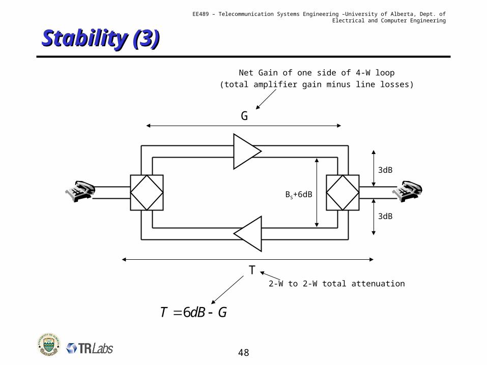
Stability (3)Stability (3)
3dB
3dB
BS+6dB
G
Net Gain of one side of 4-W loop(total amplifier gain minus line losses)
T2-W to 2-W total attenuation
6T dB G
49
EE489 – Telecommunication Systems Engineering –University of Alberta, Dept. of Electrical and Computer Engineering
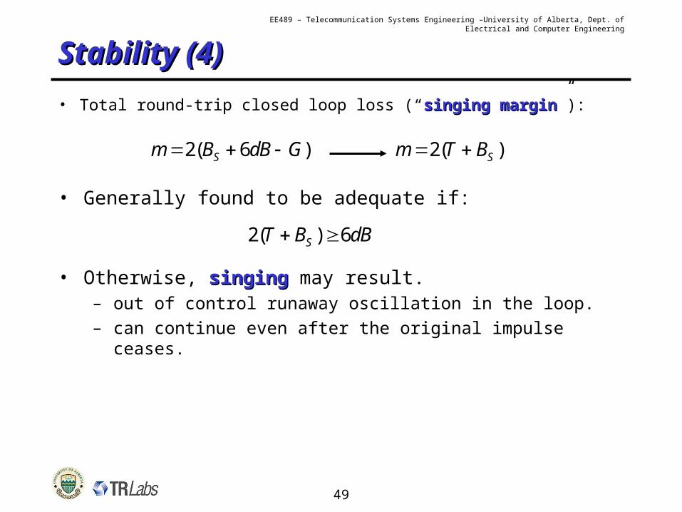
Stability (4)Stability (4)
• Total round-trip closed loop loss (“singing marginsinging margin”):
2( 6 )Sm B dB G 2( )Sm T B
• Generally found to be adequate if:
2( ) 6ST B dB
• Otherwise, singingsinging may result.– out of control runaway oscillation in the loop.– can continue even after the original impulse ceases.
50
EE489 – Telecommunication Systems Engineering –University of Alberta, Dept. of Electrical and Computer Engineering
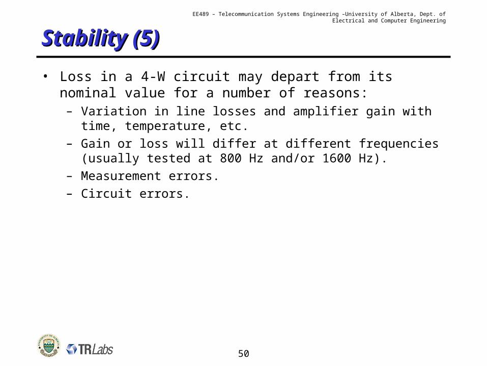
Stability (5)Stability (5)
• Loss in a 4-W circuit may depart from its nominal value for a number of reasons:– Variation in line losses and amplifier gain with time,
temperature, etc.– Gain or loss will differ at different frequencies (usually