N.P.R COLLEGE OF ENGINEERING AND TECHNOLOGY NATHAM DEPARTMENT OF ELECTRICAL AND ELECTRONICS ENGG LECTURE NOTES Electric Energy Generation, Conservation and Utilization SUB CODE : EE1452 FACULTY NAME : R SATHISH KUMAR DESIGNATION : ASSISTANT PROFESSOR YEAR/SEM :IV/VIII ACADEMIC YEAR 2012-2013
Transcript
N.P.R COLLEGE OF ENGINEERING AND TECHNOLOGY
NATHAM
DEPARTMENT OF ELECTRICAL AND ELECTRONICS ENGG
LECTURE NOTES
Electric Energy Generation, Conservation and Utilization
SUB CODE : EE1452
FACULTY NAME : R SATHISH KUMAR
DESIGNATION : ASSISTANT PROFESSOR
YEAR/SEM :IV/VIII
ACADEMIC YEAR 2012-2013
EE1452 – ELECTRIC ENERGY GENERATION, CONSERVATION AND UTILIZATION
L T P C
3 0 0 3
UNIT I GENERATION
Generation of electrical power by conventional methods: A brief review – Electrical systems in
Aircrafts and Ships – Distributed Generation (DG): Prospects and challenges – Effect of DG on
system operation.
UNIT II CONSERVATION 9
Economics of generation – Definitions – Load curves – Number and size of units – Cost of
electrical energy – Tariff – Need for electrical energy conservation – Methods – Energy efficient
equipment – Energy management – Energy auditing – Economics of power factor improvement
–Design for improvement of power factor using power capacitors – Power quality – Effect on
conservation.
UNIT III ILLUMINATION AND ELECTROLYTIC PROCESSES 9
Nature of radiation –Solid and Plane angle and its relation – Definition – Basic Laws
Photometry– Lighting Schemes – Lighting calculations – Design of illumination systems (for
residential,industrial, commercial, health care, street lighting, sports, administrative complexes)
– Types oflamps – Energy efficiency lamps – Design of choke and capacitor – Electrolytic
Process – Basicprinciples – Electro-deposition – Extraction and refining of metals methods –
Power supply for electrolytic processes.
UNIT IV ELECTRIC TRACTION 9
Basic concepts of electric Traction – Requirements of an ideal traction system – Supply systems
–Mechanics of train movement – Traction motors and control – Multiple units – Braking –
Current collection systems – Recent trends in electric traction.
UNIT V ELECTRIC HEATING AND WELDING 9
Introduction – Methods of heating – requirement of heating material – Design of heating element
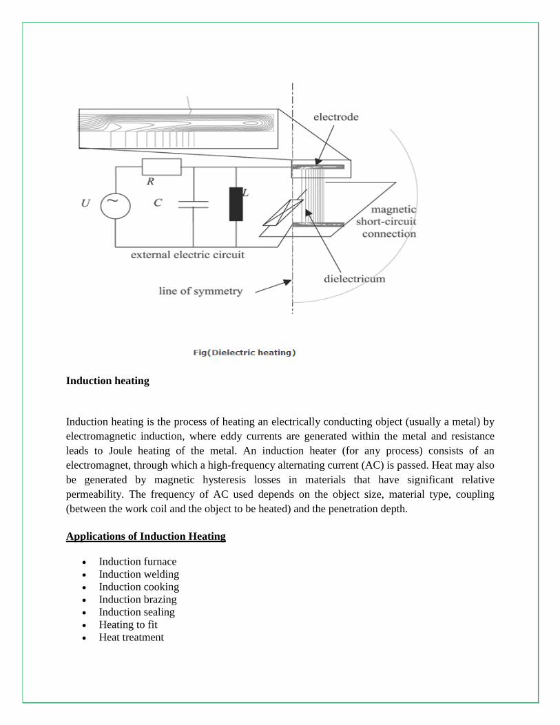
–Electric Arc Furnaces – Induction Heating – Dielectric Heating – Electric Welding –Types of
Resistance welding – Welding transformer and its characteristics – Thyristorised Control circuit
of welding – Energy storage system for welding.
Total: 45
TEXT BOOKS
1. Uppal, S.L. and Rao, S., “Electrical Power Systems”, Khanna Publishers, 2009.
2. Wadhwa, C.L., “Generation, Distribution and Utilization of Electrical Energy”, New Age
International (P) Ltd, 2003.
REFERENCES
1. Partab, H., “Art and Science of Utilisation of Electrical Energy”, Dhanpat Rai and Co,
2004.
2. Gupta, B.R., “Generation of Electrical Energy”, Eurasia Publishing House (P) Ltd, 2003.
3. Rao, S., “Testing Commissioning Operation and Maintenance of Electrical Equipments”,
Khanna Publishers, 2007.
4. Anne Marie Borbely, Anne Marie Borbely, Jan F. Kreider., “Distributed Generation: The
Power Paradigm for the New Millenium”, CRC Press, 2001
UNIT –I
GENERATION
1. Introduction
In this lesson a brief idea of a modern power system is outlined. Emphasis is given to create a clear
mental picture of a power system to a beginner of the course Electrical Technology. As consumers,
we use electricity for various purposes such as:
1. Lighting, heating, cooling and other domestic electrical appliances used in home.
2. Street lighting, flood lighting of sporting arena, office building lighting, powering PCs etc.
3. Irrigating vast agricultural lands using pumps and operating cold storages for various
agricultural products.
4. Running motors, furnaces of various kinds, in industries.
5. Running locomotives (electric trains) of railways.
1.1 Basic idea of generation
Prior to the discovery of Faraday‟s Laws of electromagnetic discussion, electrical power was
available from batteries with limited voltage and current levels. Although complicated in
construction, D.C generators were developed first to generate power in bulk. However, due to
limitation of the D.C machine to generate voltage beyond few hundred volts, it was not economical
to transmit large amount of power over a long distance. For a given amount of power, the current
magnitude (I = P/V), hence section of the copper conductor will be large. Thus generation,
transmission and distribution of d.c power were restricted to area of few kilometer radius with no
interconnections between generating plants. Therefore, area specific generating stations along with
its distribution networks had to be used.
2. Thermal, hydel & nuclear power stations
In this section we briefly outline the basics of the three most widely found generating stations –
thermal, hydel and nuclear plants in our country and elsewhere.
2.1 Thermal plant
We have seen in the previous section that to generate voltage at 50 Hz we have to run the generator
at some fixed rpm by some external agency. A turbine is used to rotate the generator. Turbine may be
of two types, namely steam turbine and water turbine. In a thermal power station coal is burnt to
produce steam which in turn, drives the steam turbine hence the generator (turbo set). In figure 2.2
the elementary features of a thermal power plant is shown.
In a thermal power plant coil is burnt to produce high temperature and high pressure steam in a
boiler. The steam is passed through a steam turbine to produce rotational motion. The generator,
mechanically coupled to the turbine, thus rotates producing electricity. Chemical energy stored in
coal after a couple of transformations produces electrical energy at the generator terminals as
depicted in the figure. Thus proximity of a generating station nearer to a coal reserve and water
sources will be most economical as the cost of transporting coal gets reduced. In our country coal is
available in abundance and naturally thermal power plants are most popular. However, these plants
pollute the atmosphere because of burning of coals.
Figure 2.1: Basic components of a thermal generating unit.
Stringent conditions (such as use of more chimney heights along with the compulsory use of
electrostatic precipitator) are put by regulatory authorities to see that the effects of pollution is
minimized. A large amount of ash is produced every day in a thermal plant and effective handling of
the ash adds to the running cost of the plant. Nonetheless 57% of the generation in out country is
from thermal plants. The speed of alternator used in thermal plants is 3000 rpm which means 2-pole
alternators are used in such plants.
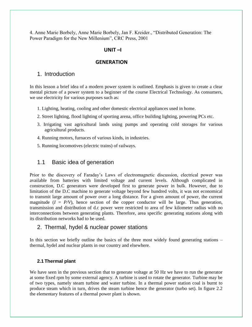
2.2 Hydel plants In a hydel power station, water head is used to drive water turbine coupled to the generator. Water
head may be available in hilly region naturally in the form of water reservoir (lakes etc.) at the hill
tops. The potential energy of water can be used to drive the turbo generator set installed at the base of
the hills through piping called pen stock. Water head may also be created artificially by constructing
dams on a suitable river. In contrast to a thermal plant, hydel power plants are eco-friendly, neat and
clean as no fuel is to be burnt to produce electricity. While running cost of such plants are low, the
initial installation cost is rather high compared to a thermal plants due to massive civil construction
necessary. Also sites to be selected for such plants depend upon natural availability of water
reservoirs at hill tops or availability of suitable rivers for constructing dams. Water turbines generally
operate at low rpm, so number of poles of the alternator are high. For example a 20-pole alternator
the rpm of the turbine is only 300 rpm.
Figure 2.2: Basic components of a hydal generating unit.
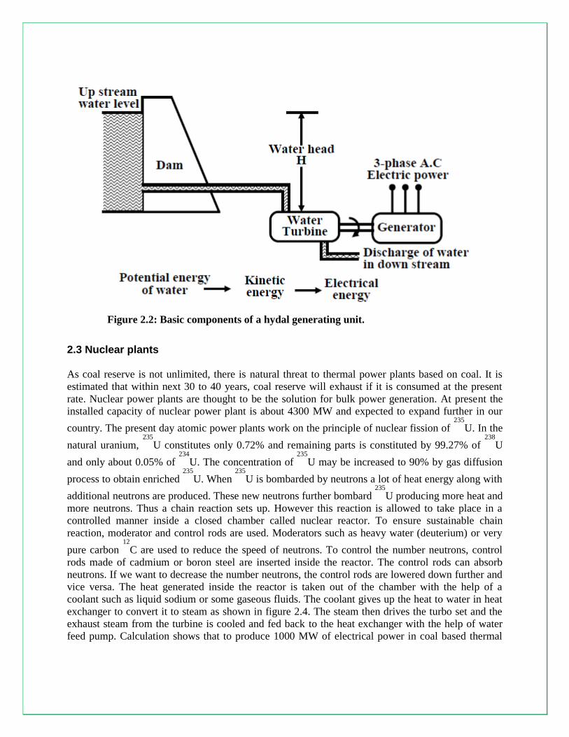
2.3 Nuclear plants As coal reserve is not unlimited, there is natural threat to thermal power plants based on coal. It is
estimated that within next 30 to 40 years, coal reserve will exhaust if it is consumed at the present
rate. Nuclear power plants are thought to be the solution for bulk power generation. At present the
installed capacity of nuclear power plant is about 4300 MW and expected to expand further in our
country. The present day atomic power plants work on the principle of nuclear fission of 235
U. In the
natural uranium, 235
U constitutes only 0.72% and remaining parts is constituted by 99.27% of 238
U
and only about 0.05% of 234
U. The concentration of 235
U may be increased to 90% by gas diffusion
process to obtain enriched 235
U. When 235
U is bombarded by neutrons a lot of heat energy along with
additional neutrons are produced. These new neutrons further bombard 235
U producing more heat and
more neutrons. Thus a chain reaction sets up. However this reaction is allowed to take place in a
controlled manner inside a closed chamber called nuclear reactor. To ensure sustainable chain
reaction, moderator and control rods are used. Moderators such as heavy water (deuterium) or very
pure carbon 12
C are used to reduce the speed of neutrons. To control the number neutrons, control
rods made of cadmium or boron steel are inserted inside the reactor. The control rods can absorb
neutrons. If we want to decrease the number neutrons, the control rods are lowered down further and
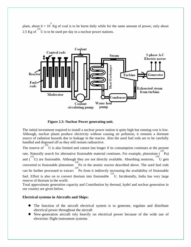
vice versa. The heat generated inside the reactor is taken out of the chamber with the help of a
coolant such as liquid sodium or some gaseous fluids. The coolant gives up the heat to water in heat
exchanger to convert it to steam as shown in figure 2.4. The steam then drives the turbo set and the
exhaust steam from the turbine is cooled and fed back to the heat exchanger with the help of water
feed pump. Calculation shows that to produce 1000 MW of electrical power in coal based thermal
plant, about 6 × 10⁶
Kg of coal is to be burnt daily while for the same amount of power, only about
2.5 Kg of 235
U is to be used per day in a nuclear power stations.
Figure 2.3: Nuclear Power generating unit.
The initial investment required to install a nuclear power station is quite high but running cost is low.
Although, nuclear plants produce electricity without causing air pollution, it remains a dormant
source of radiation hazards due to leakage in the reactor. Also the used fuel rods are to be carefully
handled and disposed off as they still remain radioactive.
The reserve of 235
U is also limited and cannot last longer if its consumption continues at the present
rate. Naturally search for alternative fissionable material continues. For example, plutonium (239
Pu)
and (233
U) are fissionable. Although they are not directly available. Absorbing neutrons, 238
U gets
converted to fissionable plutonium 239
Pu in the atomic reactor described above. The used fuel rods
can be further processed to extract 239
Pu from it indirectly increasing the availability of fissionable
fuel. Effort is also on to convert thorium into fissionable 233
U. Incidentally, India has very large
reserve of thorium in the world.
Total approximate generation capacity and Contribution by thermal, hydel and nuclear generation in
our country are given below.
Electrical systems in Aircrafts and Ships:
The function of the aircraft electrical system is to generate, regulate and distribute
electrical power throughout the aircraft
New-generation aircraft rely heavily on electrical power because of the wide use of
electronic flight instrument systems
Electrical Power Uses
Aircraft electrical power is used to operate:
Aircraft Flight Instruments
Essential Systems
Passenger Services
Essential power is power that the aircraft needs to be able to continue safe operation
Passenger services power is the power that used for:
Cabin lighting
Operation of entertainment systems
Preparation of food
Power Used
Aircraft electrical components operate on many different voltages both AC and
DC
However, most of the systems use:
– 115 VAC @ 400 Hz
– 28 VDC
26 VAC is also used in some aircraft for lighting
Power Sources
There are several different power sources on large aircraft to be able to handle excessive
loads, for redundancy, and for emergency situations.
These power sources include:
– Engine driven AC generators
– Auxiliary Power Units
– External power
– Ram Air Turbines
Most often the APUs power is used while the aircraft is on the ground during
maintenance or for engine starting
However, most aircraft can use the APU while in flight as a backup power source
– One exception to this is the B272, which only allows APU operation in the
ground
External power may only be used with the aircraft on the ground
This system utilizes a Ground Power Unit (GPU) to provide AC power through an
external plug on the nose of the aircraft
GPUs may be either portable or stationary units
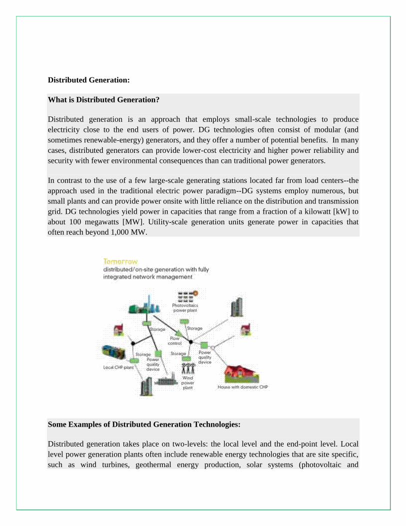
Distributed Generation:
What is Distributed Generation?
Distributed generation is an approach that employs small-scale technologies to produce
electricity close to the end users of power. DG technologies often consist of modular (and
sometimes renewable-energy) generators, and they offer a number of potential benefits. In many
cases, distributed generators can provide lower-cost electricity and higher power reliability and
security with fewer environmental consequences than can traditional power generators.
In contrast to the use of a few large-scale generating stations located far from load centers--the
approach used in the traditional electric power paradigm--DG systems employ numerous, but
small plants and can provide power onsite with little reliance on the distribution and transmission
grid. DG technologies yield power in capacities that range from a fraction of a kilowatt [kW] to
about 100 megawatts [MW]. Utility-scale generation units generate power in capacities that
often reach beyond 1,000 MW.
Some Examples of Distributed Generation Technologies:
Distributed generation takes place on two-levels: the local level and the end-point level. Local
level power generation plants often include renewable energy technologies that are site specific,
such as wind turbines, geothermal energy production, solar systems (photovoltaic and
combustion), and some hydro-thermal plants. These plants tend to be smaller and less centralized
than the traditional model plants. They also are frequently more energy and cost efficient and
more reliable. Since these local level DG producers often take into account the local context, the
usually produce less environmentally damaging or disrupting energy than the larger central
model plants.
Distributed generation–impact on the system operation:
Impact of DG on power system
• Power Quality - at each unit
– Starting and stopping
– Flicker from tower shadow effect
• Power balance - at large penetration
– Non dispatchable, ”must run” units
– Uncontrolled, negative loads
– Wind power production hard to predict
• Protection - of network and units
Distributed Generation Advantages:
• Size for Base load Capacity to Meet
Minimum Constant Loads
• Capture Intermittent and Peaking Loads
in Residential and Commercial Cogeneration
• Increased Energy Efficiency
• Reduced Emissions
UNIT –2
CONSERVATION
Economics of Power Generation:
Introduction to Economics of Power Generation:
The function of a power station is to deliver power at the lowest possible cost per kilo watt hour.
This total cost is made up of fixed charges consisting of interest on the capital, taxes, insurance,
depreciation and salary of managerial staff, the operating expenses such as cost of fuels, water,
oil, labor, repairs and maintenance etc.
The cost of power generation can be minimized by :
1. Choosing equipment that is available for operation during the largest possible % of time in a
year.
2. Reducing the amount of investment in the plant.
3. Operation through fewer men.
4. Having uniform design
5. Selecting the station as to reduce cost of fuel, labor, etc.
All the electrical energy generated in a power station must be consumed immediately as it cannot
be stored. So the electrical energy generated in a power station must be regulated according to
the demand. The demand of electrical energy or load will also vary with the time and a power
station must be capable of meeting the maximum load at any time. Certain definitions related to
power station practice are given below:
Load curve :
Load curve is plot of load in kilowatts versus time usually for a day or a year.
Load duration curve :
Load duration curve is the plot of load in kilowatts versus time duration for which it occurs.
Maximum demand :
Maximum demand is the greatest of all demands which have occurred during a given period of
time.
Average load :
Average load is is the average load on the power station in a given period (day/month or year)
Base load :
Base load is the minimum load over a given period of time.
Connected load :
Connected load of a system is the sum of the continuous ratings of the load consuming apparatus
connected to the system.
Peak load :
Peak load is the maximum load consumed or produced by a unit or group of units in a stated
period of time. It may be the maximum instantaneous load or the maximum average load over a
designated interval of time.
Demand factor :
Demand factor is the ratio of maximum demand to the connected load of a consumer.
Diversity factor :
Diversity factor is the ratio of sum of individual maximum demands to the combined maximum
demand on power stations
Load factor :
Load factor is the ratio of average load during a specified period to the maximum load occurring
during the period.
Load factor = Average Load / Maximum demand
Station load factor :
Station load factor is the ratio of net power generated to the net maximum demand on a power
station.
Plant factor :
Plant factor is the ratio of the average load on the plant for the period of time considered, to the
aggregate rating of the generating equipment installed in the plant.
Capacity factor :
Capacity factor is the ratio of the average load on the machine for a period of time considered, to
the rating of the machine.
Demand factor :
Demand factor is the ratio of maximum demand of system or part of system, to the total
connected load of the system, or part of system, under consideration.
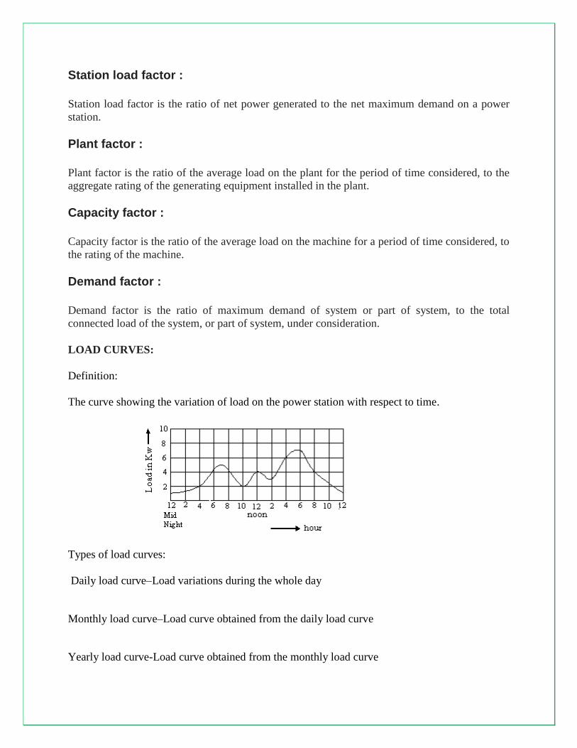
LOAD CURVES:
Definition:
The curve showing the variation of load on the power station with respect to time.
Types of load curves:
Daily load curve–Load variations during the whole day
Monthly load curve–Load curve obtained from the daily load curve
Yearly load curve-Load curve obtained from the monthly load curve
Load Characteristics:
Connected load
Maximum demand
Average load
Load factor
Diversity factor
Plant capacity factor
Plant use factor
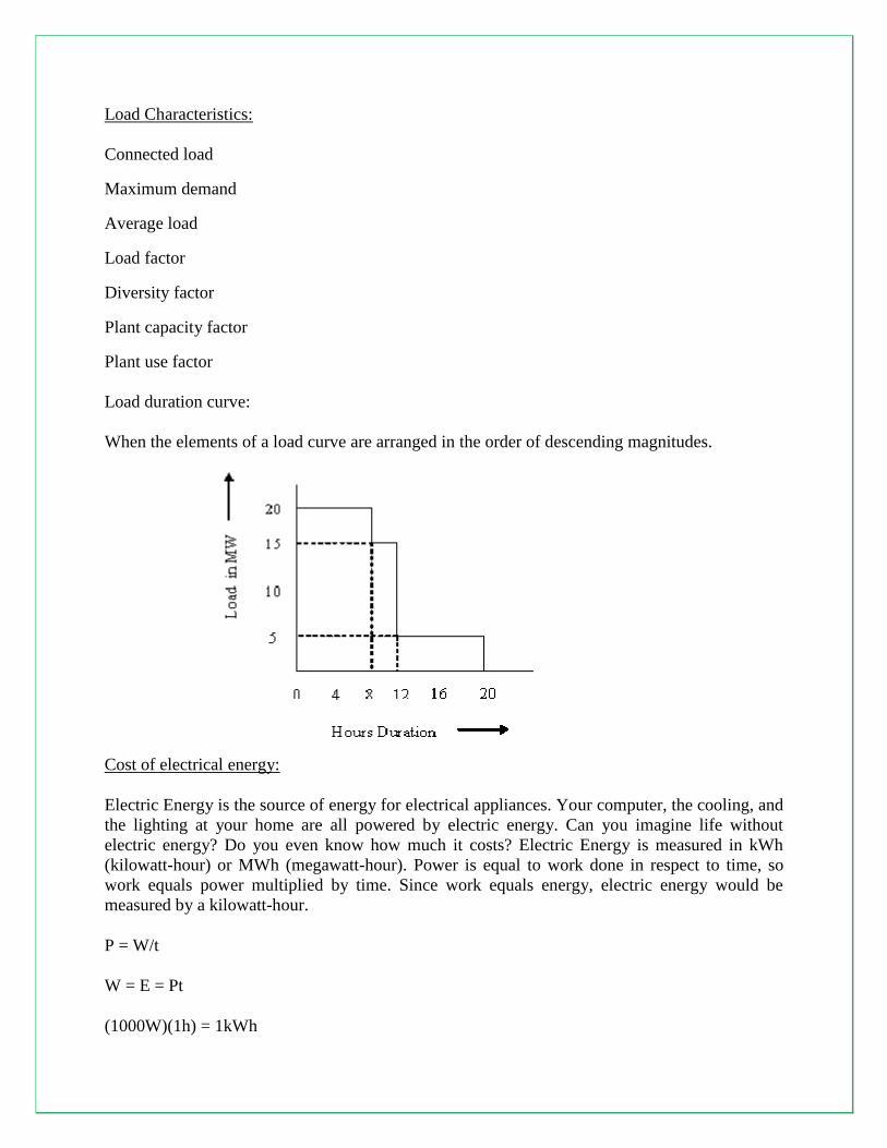
Load duration curve:
When the elements of a load curve are arranged in the order of descending magnitudes.
Cost of electrical energy:
Electric Energy is the source of energy for electrical appliances. Your computer, the cooling, and
the lighting at your home are all powered by electric energy. Can you imagine life without
electric energy? Do you even know how much it costs? Electric Energy is measured in kWh
(kilowatt-hour) or MWh (megawatt-hour). Power is equal to work done in respect to time, so
work equals power multiplied by time. Since work equals energy, electric energy would be
measured by a kilowatt-hour.
P = W/t
W = E = Pt
(1000W)(1h) = 1kWh
The cost of each kWh depends on your location and the company you use. In New York, the
average kWh costs 14.31 cents, but it can cost as high as 16.73 cents in Hawaii or as low as 5.81
cents in Kentucky. You're probably thinking that's not so expensive, but when it all adds up, the
number can become significant. Just look at your electric bill. An electric bill in New York can
come out to be $81.68, depending on which appliances are being used. But imagine your electric
bill when you're blasting your air conditioner. It can cost you a few hundred dollars. But you can
decrease that cost by using more of your fan in place of your air conditioner because a typical fan
would cost you in the teens rather than in the hundreds. This is mainly due to the amount of watts
used to power your electric appliances. An air conditioner can use up to a few thousand watts,
while a fan would only use a few hundred watts. If you want to keep your electric bill low,
substitute high watt appliances for low watt appliances.
Energy conservation:
Energy conservation refers to efforts made to reduce energy consumption. Energy conservation
can be achieved through increased efficient energy use, in conjunction with decreased energy
consumption and/or reduced consumption from conventional energy sources
Energy being an important element of the infrastructure sector has to be ensured its availability
on sustainable basis. On the other hand, the demand for energy is growing manifold and the
energy sources are becoming scarce and costlier. Among the various strategies to be evolved for
meeting energy demand, efficient use of energy and its conservation emerges out to be the least
cost option in any given strategies, apart from being environmentally benign.
The steps to create sustainable energy system begin with the wise use of resources; energy
efficiency is the mantra that leads to sustainable energy management.
Energy Demand And Supply
On the energy demand and supply side, India is facing severe shortages. 70% of the total
petroleum product demand is being met by imports, imposing a heavy burden on foreign
exchange. Country is also facing Peak power and average energy shortages of 12% and 7%
respectively. To provide power for all , additional capacity of 100,000 MW would be needed by
2012, requiring approximately Rs.8000 billion investment. Further, the per capita energy
consumption in India is too low as compared to developed countries, which is just 4% of USA
and 20% of the world average. The per capita consumption is targeted to grow to about 1000
kWh per year by 2012 , thus imposing extra demand on power system.
Importance Of Energy Conservation
In a scenario where India tries to accelerate its development process and cope with increasing
energy demands, conservation and energy efficiency measures are to play a central role in our
energy policy. A national movement for energy conservation can significantly reduce the need
for fresh investment in energy supply systems in coming years. It is imperative that all-out
efforts are made to realize this potential. Energy conservation is an objective to which all the
The sensitivity of the human eye to light varies with wavelength. A light source with a radiance
of one watt/m2
-steradian of green light, for example, appears much brighter than the same source
with a radiance of one watt/m2
-steradian of red or blue light. In photometry, we do not measure
watts of radiant energy. Rather, we attempt to measure the subjective impression produced by
stimulating the human eye-brain visual system with radiant energy.
This task is complicated immensely by the eye‟s nonlinear response to light. It varies not only
with wavelength but also with the amount of radiant flux, whether the light is constant or
flickering, the spatial complexity of the scene being perceived, the adaptation of the iris and
retina, the psychological and physiological state of the observer, and a host of other variables.
Nevertheless, the subjective impression of seeing can be quantified for “normal” viewing
conditions. In 1924, the Commission Internationale d‟Eclairage (International Commission on
Illumination, or CIE) asked over one hundred observers to visually match the “brightness” of
monochromatic light sources with different wavelengths under controlled conditions. The
statistical result -- the so-called CIE photometric curve shown ,the photopic luminous efficiency
of the human visual system as a function of wavelength. It provides a weighting function that can
be used to convert radiometric into photometric measurements.
Photometric theory does not address how we perceive colors. The light being measured can be
monochromatic or a combination or continuum of wavelengths; the eye‟s response is determined
by the CIE weighting function. This underlines a crucial point: The only difference between
radiometric and photometric theory is in their units of measurement. With this thought firmly in
mind, we can quickly review the fundamental concepts of photometry.
Luminous Flux (Luminous Power)
Luminous flux is photometrically weighted radiant flux (power). Its unit of measurement is the
lumen, defined as 1/683 watts of radiant power at a frequency of 540 x 1012
Hertz. As with
luminous intensity, the luminous flux of light with other wavelengths can be calculated using the
CIE photometric curve.
Luminous Energy
Luminous energy is photometrically weighted radiant energy. It is measured in lumen seconds.
Luminous Flux Density (Illuminance and Luminous Exitance)
Luminous flux density is photometrically weighted radiant flux density. Illuminance is the
photometric equivalent of irradiance, whereas luminous exitance is the photometric equivalent of
radiant exitance.
Luminous flux density is measured in lumens per square meter. (A footcandle is one lumen per
square foot.)
Lighting Calculations:
Inverse-square law
The skilled application of computerized point lighting calculations can optimize lighting levels in
both the task and ambient domains in order to minimize energy consumption. The lighting
professional should consider the use of point lighting calculations, both to design more energy-
efficient spaces, and to create spaces with more drama and visual interest.
Point calculations are an exceptionally accurate way to compare general lighting systems. While
the easier lumen method allows the comparison of average illuminance, point calculations permit
the comparison of uniformity of light on the work plane, the patterns of light produced on
ceilings and walls, and task contrast rendering. More specifically, point calculations allow
consideration of the effects listed below.
Effect on Room Surfaces. By evaluating the patterns of light on a wall caused by a row of
compact fluorescent down lights, an aesthetic evaluation can be made. Artwork locations
may be selected or lighting may be designed to highlight artwork. It may also be possible
to determine whether the pattern created on a wall will produce luminance extremes that
will cause glare or reflections in VDT screens.
Indirect Lighting Effects on Ceiling. When they are too close to the ceiling, indirect
lighting systems may create definite stripes or pools of light on the ceiling that are
distracting and that may image in VDT screens. Careful ceiling luminance calculations
can help identify the problem, and allow comparison of lighting products with various
optical distributions and suspension lengths to reduce the effect. Gray-scale printouts or
shaded VDT screen output of luminance make visual assessments possible.
Interior Task-Ambient Lighting. Point calculations should be used for any type of
lighting design where the task locations and types are well known and are unlikely to
move without a lighting redesign. They may also be used for lighting designs where tasks
that move end up in predefined locations.
Cautions for Point Calculations. In the case where a task light is used, or where an indirect
fixture is mounted within 12 inches of the ceiling, point calculations are not always appropriate.
In general, if the luminaire is close to the surface where lighting patterns are to be evaluated, a
near field situation exists. A shortcoming of the mathematics used in point calculations is that
these near field calculations are comparatively inaccurate unless near field photometric data is
available from the luminaire manufacturer, or the computer program is capable of adjusting the
characteristics of the luminaires to improve the accuracy of the results. Otherwise, it may be
more accurate to evaluate the light patterns from the task light or indirect fixture empirically.
The most common methods used for lighting calculations are:
(1) Watts Per Square Meter Method. This is principally a „rule of thumb‟ method very handy
for rough calculations or checking. It consists of making an allowance of watts/m2 of area
to be illuminated according to the illumination desired on the assumption of an average
figure of overall efficiency of the system.
(2) Lumen or Light Flux Method. This method is applicable to those cases where the sources
of light are such as to produce an approximate uniform illumination over the working
plane or where an average value is required. Lumens received on the working plane may
be determined from the relation.
Lumens received on the working plane = Number of lamps X wattage of each lamp X lamp
efficiency (lumens/watt) X coefficient of utilization/depreciation factor.
(3) Point-To-Point or Inverse Square Law Method. This method is applicable where the
illumination at a point due to one or more sources of light is required, the candle power of
sources in the particular direction under consideration being known. This method is not much
used because of its complicated and cumbersome applications.
Design of lighting system:
Direct lighting
Lighting provided from a source without reflection from other surfaces. In daylighting, this
means that the light has travelled on a straight path from the sky (or the sun) to the point of
interest. In electrical lighting it usually describes an installation of ceiling mounted or suspended
luminaires with mostly downward light distribution characteristics.
Indirect lighting
Lighting provided by reflection usually from wall or celiling surfaces. In daylighting, this means
that the light coming from the sky or the sun is reflected on a surface of high reflectivity like a
wall, a window sill or a special redirecting device. In electrical lighting the luminaires are
suspended from the ceiling or wall mounted and distribute light mainly upwards so it gets
reflected off the ceiling or the walls.
Types of Lighting
One of the primary functions of a luminaire is to direct the light to where it is needed. The light
distribution produced by luminaires is characterized by the Illuminating Engineering Society as
follows:
Direct Lighting ( 90 to 100 percent of the light is directed downward for maximum use.
Indirect Lighting( 90 to 100 percent of the light is directed to the ceilings and upper walls
and is reflected to all parts of a room.
Semi-Direct Lighting( 60 to 90 percent of the light is directed downward with the
remainder directed upward.
Semi-indirect Lighting ( 60 to 90 percent of the light is directed upward with the
remainder directed downward.
Highlighting Lighting( the beam projection distance and focusing ability characterize this
luminaire)
Types of lamps:
"Arc lamp" or "arc light" is the general term for a class of lamps that produce light by an electric arc (also called a voltaic arc). The lamp consists of two electrodes, first made from carbon but typically made today of tungsten, which are separated by a gas. The type of lamp is often named by the gas contained in the bulb; including neon, argon, xenon, krypton, sodium, metal halide, and mercury, or by the type of electrode as in carbon-arc lamps. The common fluorescent lamp is actually a low-pressure mercury arc lamp
High Pressure Mercury Vapour Lamp
The mercury vapour lamp in construction is similar to sodium vapour lamp. It gives greenish
blue colour light, which causes colour distortion. The efficiency is about 30-40 lumens per
watt. These lamps (MA type) are manufactured in 250 and 400 W ratings for use on 200-250 V
ac supply. Lamps of this type are used for general industrial lighting, railway yards, ports, work
areas; shopping centers etc where greenish-blue colour ligh is not objectionable. Another type,
which is manufactured in 300 and 500 W ratings for use on ac as well as dc supply mains is
MAT type. This is similar to MA type except that it does not use choke as ballast. Lower wattage
lamps, such as 80 and 125 W, are manufactured in a different design and using high vapour
pressure of about 5-10 atmospheres. These are known as MB type lamps.
Incandescent lamp:
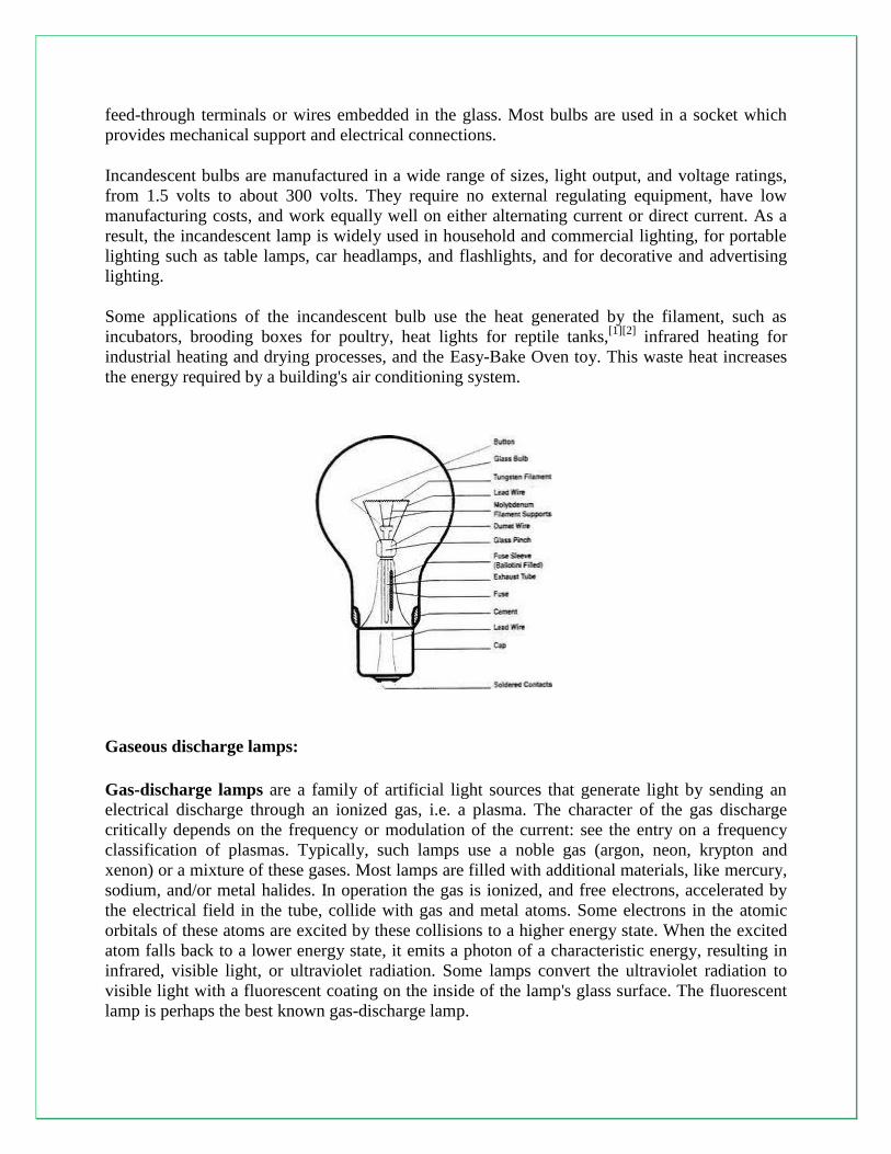
The incandescent light bulb, incandescent lamp or incandescent light globe produces light by
heating a metal filament wire to a high temperature until it glows. The hot filament is protected
from oxidation in the air with a glass enclosure that is filled with inert gas or evacuated. In a
halogen lamp, filament evaporation is prevented by a chemical process that redeposits metal
vapor onto the filament, extending its life. The light bulb is supplied with electrical current by