39
EE202 – Circuit Theory II 2017-2018, Spring Dr. Yılmaz KALKAN

EE202 – Circuit Theory II2017-2018, Spring
Dr. Yılmaz KALKAN

I. Introduction & Review of First Order Circuits (Chapter 7 of Nilsson - 3 Hrs.)
Introduction, RC and RL Circuits,
Natural and Step Responses of Series and Parallel RL/RC Circuits
II. Second Order Circuits (Chapter 8 of Nilsson - 9 Hrs.)
The Natural Response of a Parallel RLC Circuit,
The Forms of Natural Response of a Parallel RLC Circuit, The Step Response of a Parallel RLCCircuit, Natural and Step Responses of a Series RLC Circuit
III. Sinusoidal Steady-State Analysis (Chapter 9 of Nilsson - 9 Hrs.)
The Sinusoidal Source, the Sinusoidal Response, the Phasor. The Passive Circuit Elements in theFreq. Domain, Kirchhoff’s Laws in the Freq. Domain. Series, Parallel, and Delta-to-WyeSimplifications, Source Transformations Thevenin and Norton Equivalent Circuits, the Node-Voltage Method, the Mesh-Current Method. The Transformer, Mutual Coupling
IV. Sinusoidal Steady-State Power Calculations (Chapter 10 of Nilsson - 6 Hrs.)
Instantaneous Power, Average and Reactive Power, The rms Value and Power Calculations,Maximum Power Transfer
V. Balanced Three-Phase Circuits (Chapter 11 of Nilsson - 6 Hrs.)
Balanced Three-Phase Voltage, Three-Phase Voltage Sources, Analysis of the Wye-Wye and Wye-Delta Circuits, Power Calculations in Balanced Three-Phase Circuits, Measuring Average Power inThree-Phase Circuits
VI. The Laplace Transformation in Circuit Analysis (Chapter 12-13 of Nilsson - 6 Hrs.)
Circuit Elements in the s Domain, Circuit Analysis in the s Domain, The Transfer Function, TheTransfer Function in Partial Fraction Expansions, The Transfer Function and the ConvolutionIntegral, The Transfer Function and the Steady-State Sinusoidal Response, The Impulse Functionin Circuit Analysis
12.02.2018EE202 - Circuit Theory II

EE202 - Circuit Theory II

Thus far our analysis has been limited for the most part to dccircuits: those circuits excited by constant or time-invariantsources.
We have restricted the forcing function to dc sources for the sakeof simplicity, for pedagogic reasons, and also for historic reasons.
Historically, dc sources were the main means of providing electricpower up until the late 1800s. At the end of that century, thebattle of direct current versus alternating current began.
Both had their advocates among the electrical engineers of thetime. Because ac is more efficient and economical to transmit overlong distances, ac systems ended up the winner.
We now begin the analysis of circuits in which the source voltageor current is time-varying.
EE202 - Circuit Theory II

In this chapter, we are particularly interested in sinusoidally time-varying excitation, or simply, excitation by a sinusoid.
A sinusoid is a signal that has the form of the sine or cosine function.
A sinusoidal current is usually referred to as alternating current(ac). Circuits driven by sinusoidal current or voltage sources are calledac circuits. We are interested in sinusoids for a number of reasons.
Nature itself is characteristically sinusoidal. A sinusoidal signal is easy to generate and transmit. Through Fourier analysis, any practical periodic signal canbe represented by a sum of sinusoids. A sinusoid is easy to handle mathematically.
EE202 - Circuit Theory II

Consider the sinusoidal voltage;Vm = the amplitude of the sinusoidω = the angular frequency in radians/sωt = the argument of the sinusoid
EE202 - Circuit Theory II
Sinusoids
wtVtv m sin)(
It is evident that the sinusoid repeats itself every T seconds; thus, T is called the period of the sinusoid. We observe that ωT = 2π,

EE202 - Circuit Theory II
Sinusoids
)sin()( wtVtv m
The period “T” of the periodic function is the time of one completecycle or the number of seconds per cycle. The reciprocal of this quantity is the number of cycles per second,known as the cyclic frequency “f “ of the sinusoid. Thus,
Let us now consider a more general expression for the sinusoid,

EE202 - Circuit Theory II
Sinusoids
or
byvleadsv 12
byvlagsv 21
.,0
.,0
21
21
phaseinarevandvif
phaseofoutarevandvif

We can transform a sinusoid from sine form to cosine form usingtrigonometric identities.
A graphical approach may be used to relate or compare sinusoidsas an alternative to using the trigonometric identities
EE202 - Circuit Theory II
Sinusoids

The graphical technique can also be used to add two sinusoids ofthe same frequency when one is in sine form and the other is incosine form.
EE202 - Circuit Theory II
Sinusoids

EE202 - Circuit Theory II
Sinusoids
Example:

EE202 - Circuit Theory II
Sinusoids
Solution:
Example:

EE202 - Circuit Theory II
Sinusoids
Solution:
Example:

EE202 - Circuit Theory II
Sinusoids
Solution:
Example:

EE202 - Circuit Theory II
Sinusoids
Exercise:

EE202 - Circuit Theory II
Phasors
Sinusoids are easily expressed in terms of phasors, which aremore convenient to work with than sine and cosine functions.
A phasor is a complex number that represents the amplitude and phase of a sinusoid.
Phasors provide a simple means of analyzing linear circuitsexcited by sinusoidal sources; solutions of such circuits would beintractable otherwise. The notion of solving ac circuits usingphasors was first introduced by Charles Steinmetz in 1893.

EE202 - Circuit Theory II
Phasors
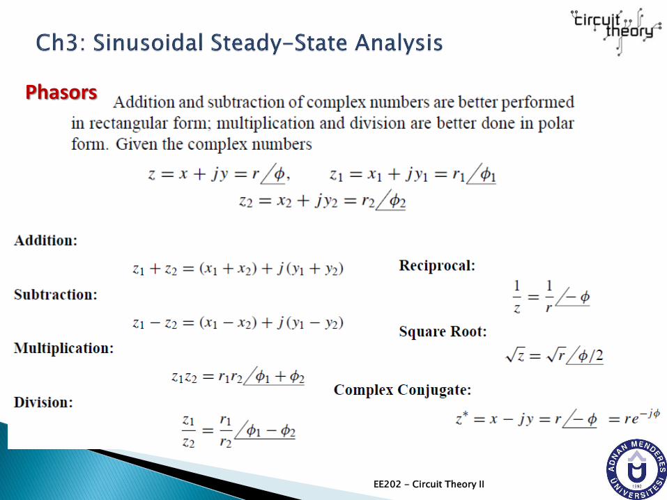
A complex number z can be written in different forms as
EE202 - Circuit Theory II
Phasors

EE202 - Circuit Theory II
Phasors
The idea of phasor representation is based on Euler’s identity. Ingeneral,
where
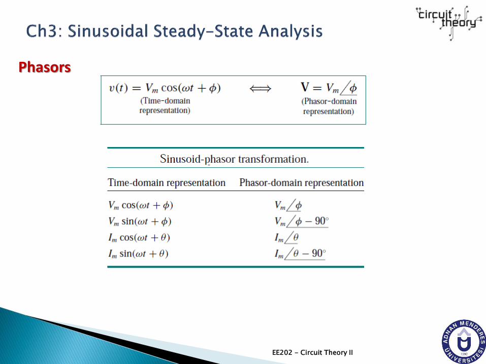
Given a sinusoid
V is the phasor representationof the sinusoid v(t). In otherwords, a phasor is a complexrepresentation of themagnitude and phase of asinusoid.

EE202 - Circuit Theory II
Phasors

EE202 - Circuit Theory II
Phasors
As a complex quantity, aphasor may be expressedin rectangular form, polarform, or exponentialform. Since a phasor hasmagnitude and phase(“direction”), it behavesas a vector and is printedin boldface.
EE202 - Circuit Theory II
Phasors

EE202 - Circuit Theory II
Example:
Phasors

EE202 - Circuit Theory II
Example:
Phasors

EE202 - Circuit Theory II
Example:
Phasors

EE202 - Circuit Theory II
Exercises:
Phasors
EE202 - Circuit Theory II
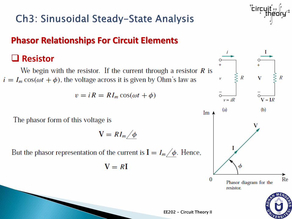
Phasor Relationships For Circuit Elements
Resistor

EE202 - Circuit Theory II
Phasor Relationships For Circuit Elements
Inductor

EE202 - Circuit Theory II
Phasor Relationships For Circuit Elements
Capacitor

EE202 - Circuit Theory II
Phasor Relationships For Circuit Elements
R, L, C Summary
EE202 - Circuit Theory II
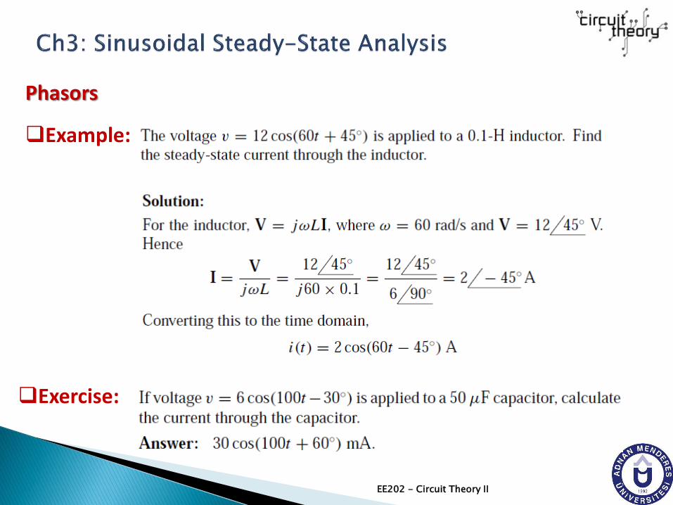
Example:
Phasors
Exercise:

EE202 - Circuit Theory II
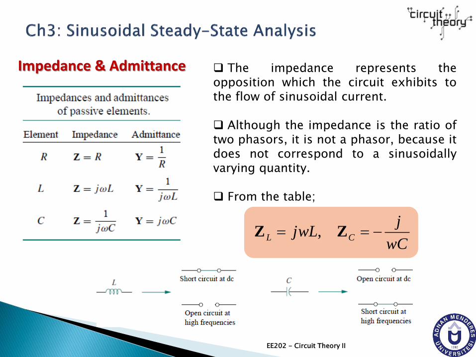
Impedance & Admittance
We obtained the voltage-current relations for the three passiveelements as
These equations may be written in terms of the ratio of thephasor voltage to the phasor current as
From these three expressions, we obtain Ohm’s law in phasorform for any type of element as
jwCjwLR
IVIVIV ,,
jwCjwLR
1,,
I
V
I
V
I
V
ZIVI
VZ or

EE202 - Circuit Theory II
Impedance & Admittance
“Z” is a frequency-dependent quantity known as impedance,measured in ohms.
ZIVI
VZ or
The impedance Z of a circuit is the ratio of the phasor voltage V to the phasor current I, measured in ohms ().
The admittance Y of a circuit is the reciprocal of Z, measured in siemens (S).
V
IY
ZY or
1
EE202 - Circuit Theory II
Impedance & Admittance The impedance represents theopposition which the circuit exhibits tothe flow of sinusoidal current.
Although the impedance is the ratio oftwo phasors, it is not a phasor, because itdoes not correspond to a sinusoidallyvarying quantity.
From the table;
wC
jjwL CL ZZ ,

EE202 - Circuit Theory II
Impedance & Admittance
As a complex quantity, the impedance may be expressed in rectangularform as
jXR Zwhere R = Re {Z} is the resistance and X = Im {Z} is the reactance.
The reactance X may be positive or negative.
We say that the impedance is inductive when X is positive or capacitivewhen X is negative.
Thus, impedance Z = R + jX is said to be inductive or lagging sincecurrent lags voltage, while impedance Z = R − jX is capacitive or leadingbecause current leads voltage.
The impedance, resistance, and reactance are all measured in ohms.The impedance may also be expressed in polar form as

EE202 - Circuit Theory II
Impedance & Admittance
As a complex quantity, the admittance may be expressed in rectangularform as
jBG Ywhere G= Re {Y} is the conductanceand B = Im {Y} is the susceptance.

EE202 - Circuit Theory II
Example:
Phasors

EE202 - Circuit Theory II
Exercise:
Phasors
END OF CHAPTER 3 (Part I)
Dr. Yılmaz KALKAN
EE202 - Circuit Theory II


