38
EE345: Introduction to Microcontrollers Register and Counters Prof. Ahmad Abu-El-Haija
| Date post: | 23-Dec-2015 |
| Category: |
Documents |
| Upload: | sheryl-horton |
| View: | 222 times |
| Download: | 2 times |

EE345: Introduction to Microcontrollers
Register and Counters
Prof. Ahmad Abu-El-Haija

April 19, 2023Digital System Design 2
Acknowledgement
This presentation is a modified version of lecture notes prepared by Dr. M. Sachdev, University of Waterloo, other slides from unidentified authors, and original slides from the publisher.
April 19, 2023EE345 - Introduction to Microcontrollers 3
Contents
Registers Shift Registers Ripple Counters Synchronous Counters Other Counters
4
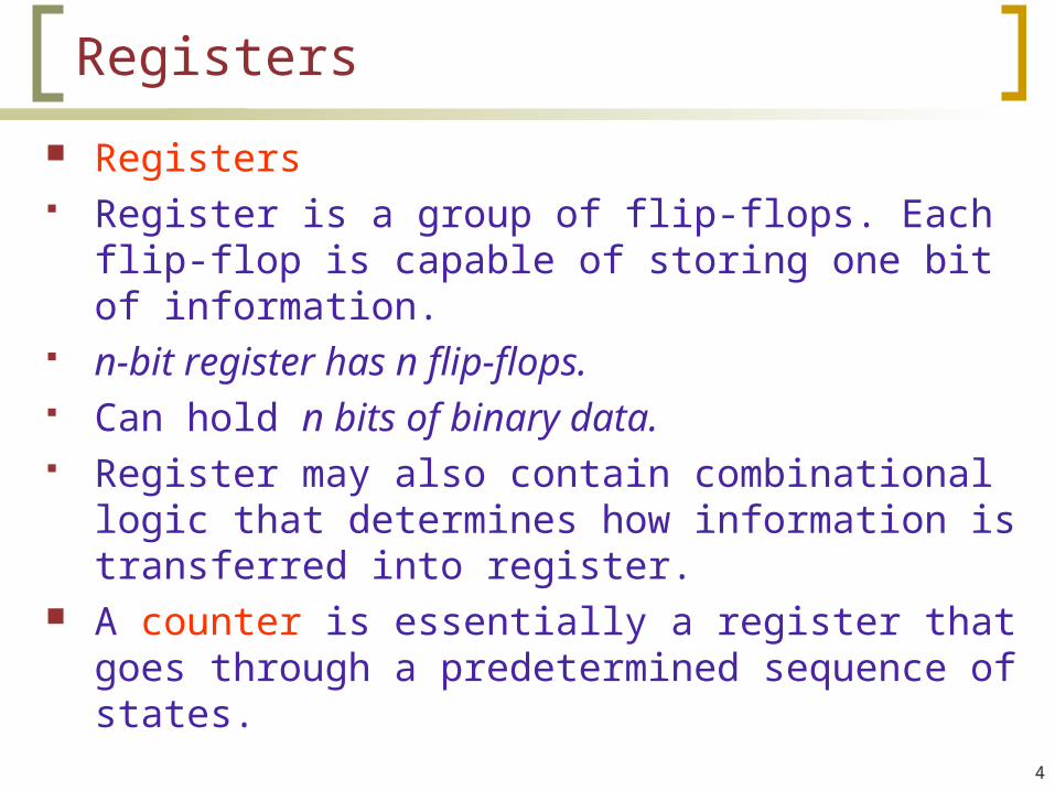
Registers
Registers Register is a group of flip-flops. Each flip-flop is
capable of storing one bit of information. n-bit register has n flip-flops. Can hold n bits of binary data. Register may also contain combinational logic that
determines how information is transferred into register.
A counter is essentially a register that goes through a predetermined sequence of states.

5
4-Bit Register
• Common clock input triggers all ff’s on positive edge of each pulse, and binary data available at inputs are transferred into register.
• Clear input is asynchronous

6
Register with Parallel Load
Specific control signal to load n-bit data
• Load =0, register retains the data
• Load = 1, register accepts new data.

7
Shift Register
Capable of shifting data in one or both directions• Clock controls the shift operation Figure shows a simple shift register with left to
right data shifting capability

8
Serial Data Transfer
Serial mode Data is transferred one bit at a time

Serial Transfer Example
April 19, 2023EE345 - Introduction to Microcontrollers 9

10
Serial Addition
Parallel adders• Faster,• cost more logic Serial adders• Slower• n-bit addition →
n clock cycles• Less hardware
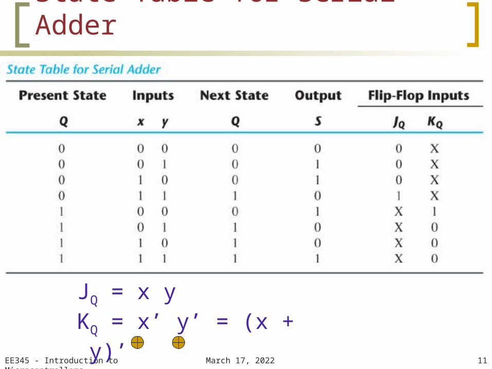
State Table for Serial Adder
April 19, 2023EE345 - Introduction to Microcontrollers 11
JQ = x yKQ = x’ y’ = (x + y)’S = x y Q
12
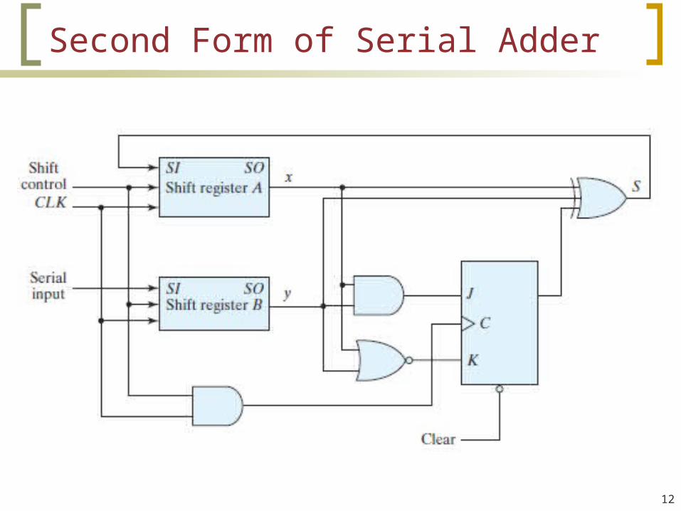
Second Form of Serial Adder

13
Universal Shift Register

14
Ripple Counters
Counters are available in two categories: ripple counters and synchronous counters.
In a ripple counter, the flip-flop output transition serves as a source for triggering other flip-flops.
In a synchronous counter, the C inputs of all flip-flops receives the common clock.
Binary and BCD ripple counters

15
Ripple (Asynchronous) Counter
Counts the binary sequence
• Negative edge triggered
• Output of one flipflop → clock to the next
• Clock skew adds up

Binary Count Sequence
April 19, 2023EE345 - Introduction to Microcontrollers 16

17
BCD Ripple Counter
A decimal counter follows a sequence of ten states and returns to 0 after the count of 9. Counter must reset itself after counting the terminal count.
A decimal counter follows a sequence of ten states and returns to 0 after the count of 9. Counter must reset itself after counting the terminal count.

18
Q1 changes state after each clock pulse.
Q2 complements every time Q1 goes from 1 to 0 as long as Q8 = 0. When Q8 becomes 1, Q2 remains at 0.
Q4 complements every time Q2 goes from 1 to 0.
Q8 remains at 0 as long as Q2 or Q4 is 0. Q8 is cleared on the next transition of Q1.
BCD Ripple Counter

19
Three-Decade Decimal BCD Counter

20
Synchronous Counter
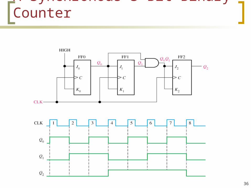
Common clock is applied to all ff’s.
Clock skew does not add up. Faster than ripple counters. Design of synchronous binary
counter is so simple that there is no need to go through sequential logic design process, but can be used.
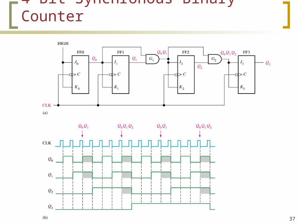
FF in least significant position is complemented with every pulse. A ff in any other position is complemented when all the bits in lower significant positions = 1.

21
Up-Down Counter
Can count up (0000 →1111) or down (1111 → 0000) binary sequence

22
Synchronous BCD CounterDesign a synchronous BCD counter with T flip-flops

23
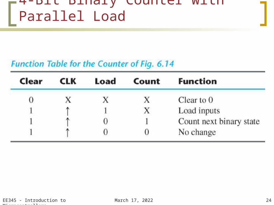
4-Bit Binary Counter with Parallel Load
Count is inhibited when is Load enabled
April 19, 2023EE345 - Introduction to Microcontrollers 24
4-Bit Binary Counter with Parallel Load

25
BCD Counter with Parallel Load

April 19, 2023EE345 - Introduction to Microcontrollers 26
A circuit with n flip-flops has 2n states• We may have to design a counter with a given sequence (unused states)• Unused states may be treated as don’t care or assigned specific next state• Outside noise may cause the counter to enter unused stateMust ensure counter eventually goes to the valid state
Counter with Unused States

27
Counter with Unused States

28
Ring Counter
A ring counter is a circular shift register with only one flip-flop being set at any particular time, all others are cleared.
The single bit is shifted from one flip-flop to the next to produce the sequence of timing signals.
The timing signals can be generated also by a 2-bit counter that goes through four distinct states.
To generate 2n timing signals, we need either a shift register with 2n flip-flops or an n-bit binary counter together with an n-to-2n-line decoder.

29
Generation of Timing Signals

30
Johnson Counter
A k-bit ring counter circulates a single bit among the flip-flops to provide k distinguishable states.
The number of states can be doubled if the shift register is connected as a switch-tail ring counter.
A switch-tail ring counter is a circular shift register with the complement output of the last flip-flop connected to the input of the first flip-flop.
In general, a k-bit switch-tail ring counter will go through a sequence of 2k states.

31
Construction of a Johnson Counter
Number of states of a ring counter can be doubled

Other Counters
April 19, 2023EE345 - Introduction to Microcontrollers 32

33
A 2-Bit Asynchronous Counter

34
3-Bit Asynchronous Counter

35
Clocked Asynchronous Decade Counter
36
A Synchronous 3-Bit Binary Counter
37
4-Bit Synchronous Binary Counter

38
3-Bit Counter


