53
1 EE373-Electrical Machines Topic 4: Three-Phase Induction (Asynchronous)

1
EE373-Electrical Machines Topic 4: Three-Phase Induction
(Asynchronous)

2
Contents
Introduction
Rotating Magnetic field
Construction and Principle of Operation
Equivalent Circuit
Performance Characteristics
Starting Methods
Speed Control

3
Introduction: Induction Motors
An induction motor is a singly-fed motor. Therefore, it
does not require a commutator, slip-rings, or brushes. In
fact, there are no moving contacts between the stator
and the rotor. This results in a motor that is rugged,
reliable, and almost maintenance free (Squirrel Cage type).
The absence of brushes eliminates the electrical loss
due to the brush voltage drop and the mechanical loss
due to friction between the brushes and commutator
or the
slip-rings (Squirrel Cage type).. Thus, an induction motor has a
relatively high efficiency.
An induction motor carries alternating current in both
the stator and the rotor windings.
An induction motor is a rotating transformer in which
the secondary winding receives energy by induction
while it rotates.

4
Application
Small single-phase induction motors are
used in many household appliances, such as
blenders, juice mixtures, washing machines,
refrigerators, etc.
Large three-phase induction motors are
used in pumps, fans, compressors, paper
mills, and so forth
In the industrial sector alone, about 75% is consumed by motors and over 90% of them are induction machines.
Simple construction, Robust, Cheap

5
Induction Motor
Induction MotorTransportation Prime-mover

Application Of Slip Ring Motor
compressorconditoiningCentral air
6
rotrWound
7
StatorRotor

8
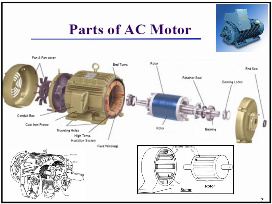
Construction
1- STATORA three-phase windings is put in slots cut on the inner surface of the stationary part. The ends of these windings can be connected in star or delta to form a three phase connection. These windings are fed from a three-phase ac supply.
Construction

9
2- Rotorit can be either:a- Squirrel-cage (brushless) (SCIM)
The squirrel-cage winding consists of bars embedded in the rotor slots and shorted at both ends by end rings.
The squirrel-cage rotor is the most common type because it is more rugged, more economical, and simpler.
Construction
/rotor winding/rotor winding
Short circuits allShort circuits allrotor bars.rotor bars.

b- Slip ring (wound-rotor) (WRIM)The wound-rotor winding has the same form as the stator winding. The windings are connected in star. The terminals of the rotor windings are connected to three slip rings. Using stationary brushes pressing against the slip rings, the rotor terminals can be connected to an external circuit.
10
Construction

Construction-Wound Rotor Induction Motor (WRIM)
Cutaway in a typical wound-
rotor IM. Notice the brushes and the slip rings
Brushes
Slip rings
11

Advantages of Slip Ring and Squirrel Cage Motor
SQUIRREL CAGE SLIP RINGcheaper and more robustslightly
the starting torque is much higher and the starting current much lower
higher efficiency and power factor
the speed can be varied by means of external rotor resistors
explosion proof, since the absence of slip-rings and brushes eliminates risk of sparking.

Type Of Asynchrounous Motor
13

14
a
b
ci
i
i
StatorStator
Stator WindingsStator Windings
RotorRotor
Rotor WindingsRotor Windings
Three-Phase Induction Motor
15
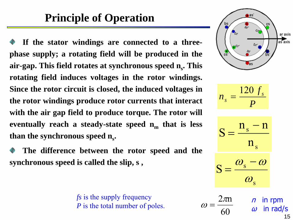
Principle of Operation
If the stator windings are connected to a three- phase supply; a rotating field will be produced in the air-gap. This field rotates at synchronous speed ns . This rotating field induces voltages in the rotor windings. Since the rotor circuit is closed, the induced voltages in the rotor windings produce rotor currents that interact with the air gap field to produce torque. The rotor will eventually reach a steady-state speed nm that is less than the synchronous speed ns .
The difference between the rotor speed and the synchronous speed is called the slip, s ,
s
s
nnn
S
s
sS
60n2 n
in rpm
ω
in rad/s
Pfn s
s120
fs is the supply frequency P is the total number of poles.

16
Rotating Magnetic Field
Currents in different phases of AC Machine
1 Cycle
Amp
timet0 t1 t2 t3 t4
t01 t12

17
MMF due to ac current in phase “a”
Axis of phase a
a’a’
-90 -40 10 60 110 160 210 260-1-0.8-0.6-0.4-0.2
00. 2
0.40.60.81
Fa
Space angle (
) in degrees
t0
t01
t12
t2
at1
a
a’
Fa
+
.
Axis of
phase a
Pulsating mmf

18
a
a’
c’ b’
b c
Fc
Fb
Fa F
t = t0
a
a’
c’ b’
b c
Fc
F
Fb
t = t1
F
a
a’
c’ b’
b c
Fb
Fa
Fc
t = t2
a
a’
c’ b’
b cFc Fb
F t = t3
-93 10 113 216-1.5
-1
-0.5
0
0.5
1
1.5
Space angle () in degrees
FFa Fc
Fb
t = t0
MMF due to three-phase currents in 3-ph winding
MMF’s
at various instant (Rotating mmf)

19
ba c
Time
t1 t3t2
Rotating Magnetic Field

20
ba c
Time
t1 t3t2 ia
ic
ib
b
c
aa
c
b
Rotating Magnetic Field
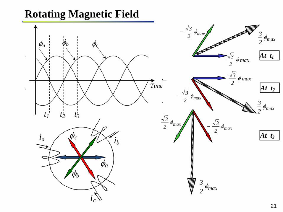
21
ba c
Time
t1 t3t2
ia
ic
ib
b
c
a
max23
max23
max23
max23
max23 max2
3
max23
max23
max23
At t1
At t2
At t3
Rotating Magnetic Field
22
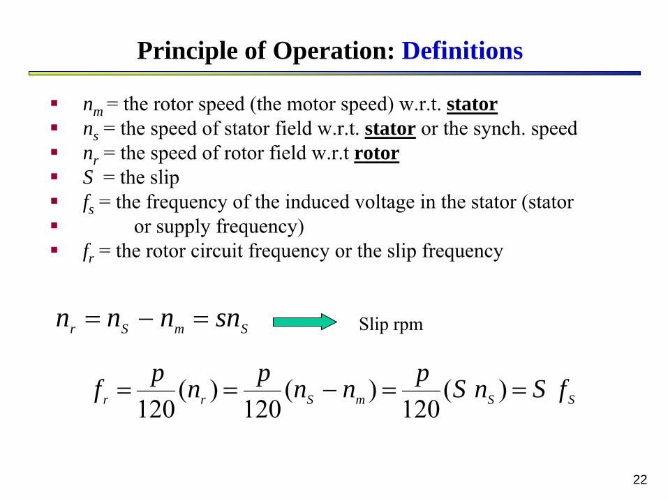
Principle of Operation: Definitions
nm = the rotor speed (the motor speed) w.r.t. stator
ns = the speed of stator field w.r.t. stator or the synch. speed
nr = the speed of rotor field w.r.t
rotor
S = the slip
fs = the frequency of the induced voltage in the stator (stator
or supply frequency)
fr = the rotor circuit frequency or the slip frequency
SmSr snnnn Slip rpm
SSmSrr fSnSpnnpnpf )(120
)(120
)(120

23
Induced EMF
wpphrms KNfE 44.4
The instantaneous value of the induced voltage in N turns coil is given by:
)90sin(2)cos(
)sin(
tfNtNe
tLetdtdNe
mm
m
The r.m.s. value of the induced voltage per phase is
whereNph is the number of turns in series per phasef is the frequencyp is the flux per pole Kw is the winding factor
phase voltage is 1/√3 of the normal voltage
phase voltage is equal to the line voltage.

241
2
1
2
NN
EE
I1
X1 R1
N1
I
E1 V
Ic
Xc Rc
Ir I2
X2 R2
N2 E2
1
2
2
12
II
NN
II
•
At standstill
(nm = 0 , S = 1)The equivalent circuit of an induction motor at standstill is the same as that of a transformer with secondary short circuited.
Equivalent Circuit Per Phase

25
•
At standstill
(nm = 0 , S = 1)The equivalent circuit of an induction motor at standstill is the same as that of a transformer with secondary short circuited.
V1
I2’
R1 R2’X1 X2
’
XcRc
IcI1
I2’
E1
=E2’ All values are
per phase
WhereE2
= per-phase induced voltage in the rotor at standstillX2 = per-phase rotor leakage reactance at standstill
Equivalent Circuit Per Phase
26
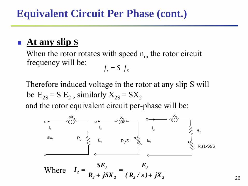
Equivalent Circuit Per Phase (cont.)
At any slip SWhen the rotor rotates with speed nm
the rotor circuit frequency will be:
Therefore induced voltage in the rotor at any slip S will be
E2S = S E2
, similarly X2S = SX2and the rotor equivalent circuit per-phase will be:
Sr fSf
sX2 X2 X2
R2
(1-S)/S
I2
sE2 R2
I2
E2 R2
/S
I2
E2
R2
22
2
22
22 jX)s/R(
EjSXR
SEI
Where
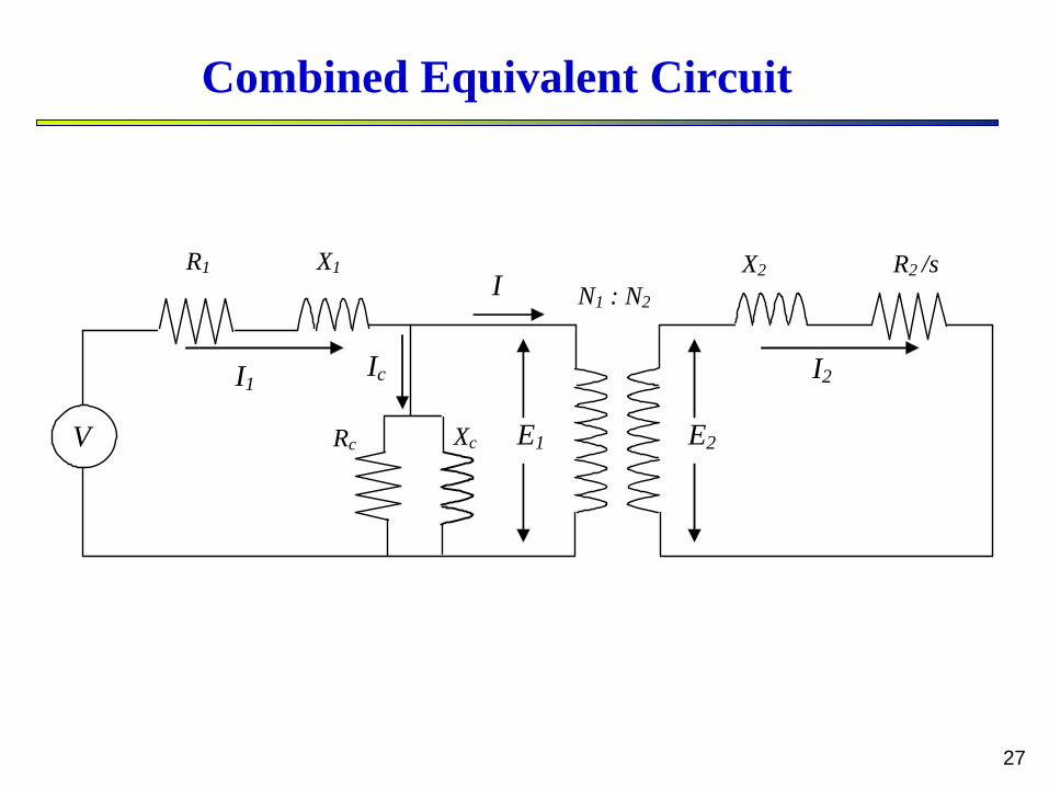
27
I2I1
X2 X1 R1 R2 /s N1 : N2
E2
I
E1
Ic
Xc Rc V
Combined Equivalent Circuit
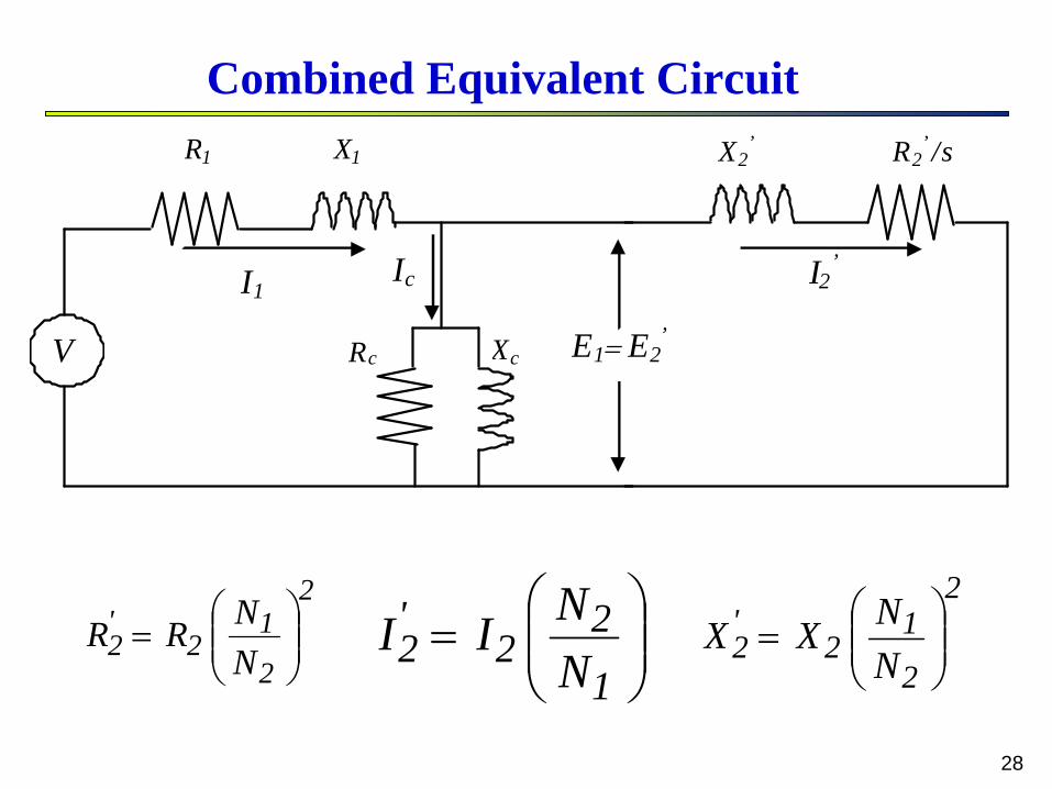
28
I2’I1
X2’X1 R1 R2
’ /s
E1 E2’
Ic
Xc Rc V
2
2
12
'2 N
NRR
2
2
12
'2 N
NXX
1
22
'2 N
NII
Combined Equivalent Circuit

29
I2’I1
X2’X1 R1 R2
’
E1 E2’
Ic
Xc Rc V )s1(s
R'2
)s1(s
RRs
R '2'
2'2
I2’I1
X2’X1 R1 R2
’ /s
E1 E2’
Ic
Xc Rc V
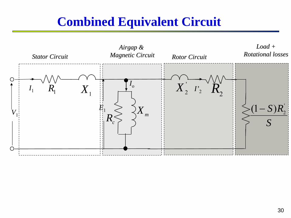
30
Io
V1
I1
E1
'2R
SRS '
2)1(
Stator Circuit Stator Circuit Rotor Circuit Rotor Circuit AirgapAirgap & &
Magnetic CircuitMagnetic Circuit
1X '2X
mX
I’2
cR
Load +Load +Rotational lossesRotational losses
1R
Combined Equivalent Circuit

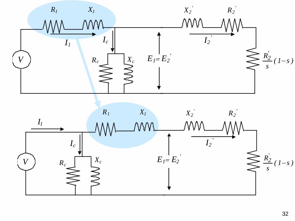
31
Equivalent to transformer’sload
Equivalent to transformer’ssecondary windings
Equivalent to transformer’sprimary windings
I2’I1
X2’X1 R1 R2
’
E1 E2’
Ic
Xc Rc V )s1(s
R'2
32
I2’
I1
X2’ R2
’
E1 E2’
X1 R1
Xc
Ic
Rc V )s1(s
R'2
I2’I1
X2’X1 R1 R2
’
E1 E2’
Ic
Xc Rc V )s1(s
R'2

33
I2’
I1 Xeq Req
Xc
Ic
Rc V )s1(s
R'2
'21eq
'21eq
XXX
RRR
Approximate Equivalent Circuit

34
1. No-Load Test ( S = 0 )
Measured values VoL = V1L , IL , and Pot = W1 ± W2
Calculate the per phase values V0 , I
and P0 = Pot
/3
)sin()cos()cos(0
omoco
o IIIIIV
P
mm
cc I
VXIVR 00
V0
Im
XmRc
Ic
IV
W1A
W2
I.M.
No Load
Determination of the Equivalent Circuit ParametersDetermination of the Equivalent Circuit Parameters

35
2. Blocked rotor Test (S =1)
Measured values VbL < V1L , IbL , and Pbt= W1
± W2
Calculate the per phase values Vb , Ib and Pb = Pot /3
V
W1A
W2
I.M.
R1
+R’2 X1
+X’2
ZbVb
Ib
Blocked
2&
,,
2112
2221221
bb
bbbb
bb
b
bb
XXXRRR
RZXXXIVZ
IPRRR
Determination of the Equivalent Circuit Parameters

36
Power Flow In Induction Motors
= 3V1 I1 cos
dev

37
Power Flow In Induction Motors
SSRIP
RIPSRIP
dev
RCL
AG
)1()(3
)(3
)(3
222
22
2
222
)1(::1:: SSPPP devRCLGA
PAG
ImV1
I2’
R1 R2’X1 X2
’
XmRc
Ic
II1
I2’
R2’(1-S)S

38
Input Power (Pin)
Stator Losses: Copper losses (Pcu 1) Core losses (Piron)
Airgap Power (Pg)
Developed Power (Pd) Rotor Copper Losses (Pcu 2)
Rotational Losses (Protational) Output Power (Pout)
Power Flow In Induction Motor
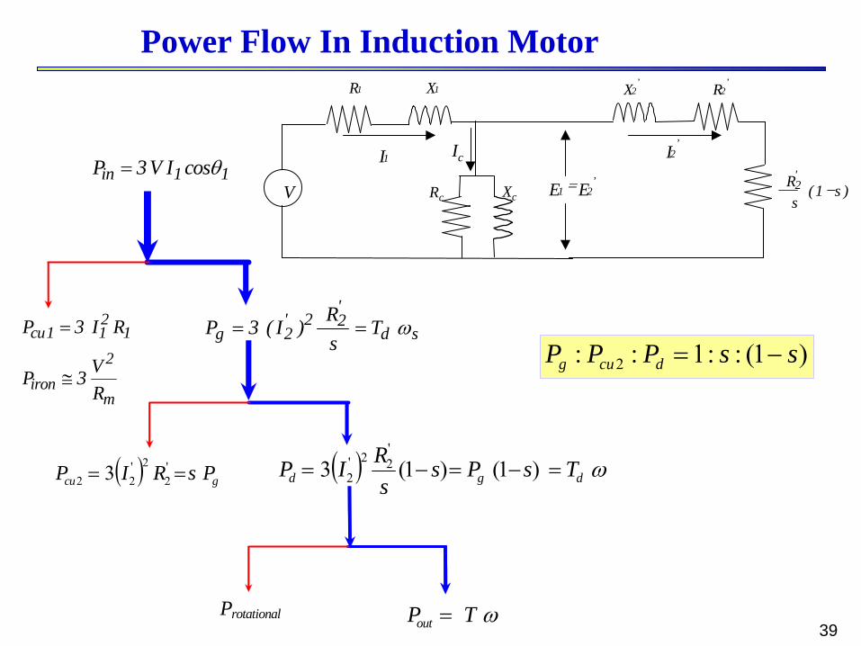
39
11in cosIV3P
m
2iron
1211cu
RV3P
RI3P
sd'22'
2g TsR)I(3P
gcu PsRIP '2
2'22 3
Protational TPout
dgd TsPss
RIP )1()1(3'22'
2
)1(::1:: 2 ssPPP dcug
I2’I1
X2’X1R1 R2
’
E1 E2’
Ic
XcRcV )s1(s
R'2
Power Flow In Induction Motor

40
Torque Characteristics
22'
21
'2
eqX
sRR
VI
I2’
I1 Xeq Req
Xc
Ic
Rc V )s1(s
R'2
d
dPT )1()(3 '
22'2 s
sRI
22'
21
'2
2 )1(3
eqXs
RRs
sRV
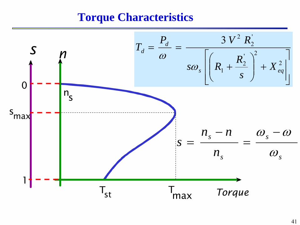
41
Torque
ns
1
0ns
Tst Tmax
smax
s
s
s
s
nnn
s
2
2'2
1
'2
23
eqs
dd
Xs
RRs
RVPT
Torque Characteristics

42
smax
TmaxT Torque
s
1
0
st
Small Slip
Large Slip
Maximum Torque
Torque Characteristics

43
2
2'2
1
'2
23
eqs
dd
Xs
RRs
RVPT
2eq
21
'2
maxXR
Rs
2eq
211s
2max
XRR2
V3T
0s
Td
Set
Maximum Torque

44
•
Problems:–
High starting current
–
Low starting torque
Starting of Induction MotorStarting of Induction Motor
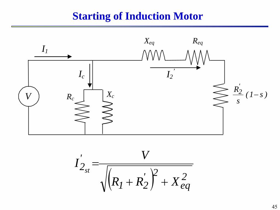
45
2eq
2'21
'2
XRR
VIst
I2’
I1 Xeq Req
Xc
Ic
Rc V )s1(s
R'2
Starting of Induction Motor

46
Starting by Reducing Voltage
Torque
n
n s
s max
Tst 1
T max Tst 2
V2 < V1
V1
2eq
2'21
'2
XRR
VIst
2eq
21
'2
maxXR
Rs
2eq
211s
2max
XRR2
V3T
2221
223
eq'
s
'
stXRR
RVT
Starting by Reducing Voltage
47
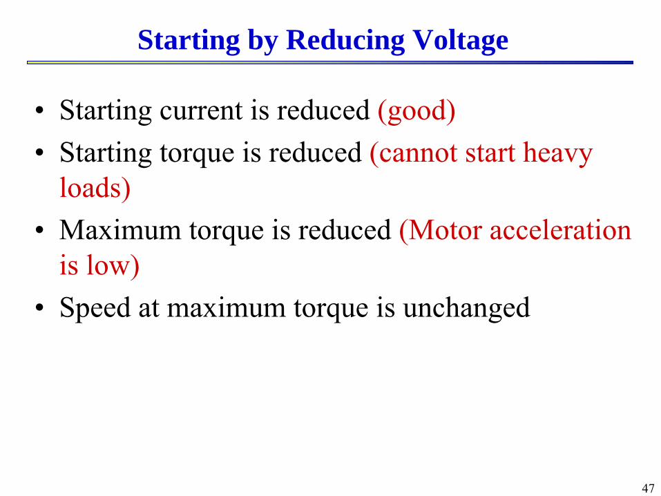
•
Starting current is reduced (good)•
Starting torque is reduced (cannot start heavy loads)
•
Maximum torque is reduced (Motor acceleration is low)
•
Speed at maximum torque is unchanged
Starting by Reducing Voltage

48
Torque
n
n s
s max
Tst1
Tst3=Tmax Tst2
Radd3 Radd2
Radd1
Radd3 > Radd2 > Radd1
2eq
2'21
'2
XRR
VIst
2eq
21
'2
maxXR
Rs
2eq
211s
2max
XRR2
V3T
2221
223
eq'
s
'
stXRR
RVT
Starting by Adding Rotor ResistanceStarting by Adding Rotor Resistance

49
Torque/Speed Curve for varying R2
•
The maximum torque is independent of the rotor resistance. However, the value of the rotor resistance determines the slip at which the maximum torque will occur. The torque-slip characteristics for various values of are shown.
•
To get maximum torque at starting ::
)(
)(23
'2
'2
max
'2
2
max
XXRS
XXVT
thT
th
th
S
)(..1 22max XXReiS thT
T
NL ~ns n
T
r1 nr2 nr3 n n
r3 n< r2 n<r1 n
1 R2 R
3 R
3 R<2 R<1 R

50
•
Starting current is reduced (good)•
Starting torque is increased (good)
•
Maximum torque is unchanged (Motor acceleration is high)
•
Speed at maximum torque is reduced
Starting by Adding Rotor Resistance

51
pfns 120
pf120n s Changing
Change f
Change p
Continuous variation
Step variation
Speed Control of IM by Changing Frequency

52
ns1
ns3
f1
f3
f2
f1 > f2 > f3
Speed
Torque
ns2
2
2
21
223
eq
'
s
'
d
Xs
RRs
RVT
2eq
211s
2max
XRR2
V3T
2221
223
eq'
s
'
stXRR
RVT
Speed Control of IM by Changing Frequency

53
Classes of squirrel-cage motors
According to the National Electrical Manufacturing Association (NEMA) criteria, squirrel-cage motors are classified into class A, B, C or D. The torque-speed curves and the design characteristics for these classes are :
Rated Load Slip
Starting Torque
Starting Current
Class
< 5%NormalNormalA< 5%NormalLowB< 5%HighLowC
8-13 %Very HighLowD
AD
C
B


