1 SM EECE 251, Set 1 EECE251 Circuit Analysis I Set 1: Basic Concepts and Resistive Circuits Shahriar Mirabbasi Department of Electrical and Computer Engineering University of British Columbia [email protected]
“The complete path of an electric current including usually the source of electric energy.”
• According to Encyclopedia Britannica:
“Path that transmits electric current.”
“A circuit includes a battery or a generator that gives energy to the charged particles; devices that use current, such as lamps, motors, or electronic computers; and connecting wires or transmission lines. Circuits can be classified according to the type of current they carry (see alternating current, direct current) or according to whether the current remains whole (series) or divides to flow through several branches simultaneously (parallel). Two basic laws that describe the performance of electric circuits are Ohm's law and Kirchhoff's circuit rules."
8 SM
EECE 251, Set 1
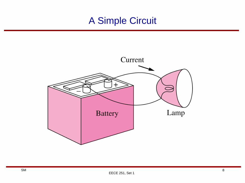
A Simple Circuit
9 SM
EECE 251, Set 1
A More Complicated Circuit
A Radio Receiver
10 SM
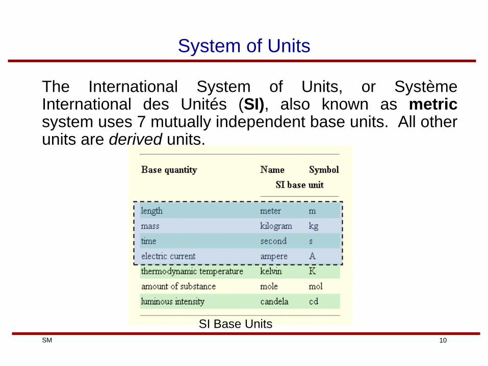
System of Units
The International System of Units, or Système International des Unités (SI), also known as metric system uses 7 mutually independent base units. All other units are derived units.
SI Base Units
11 SM
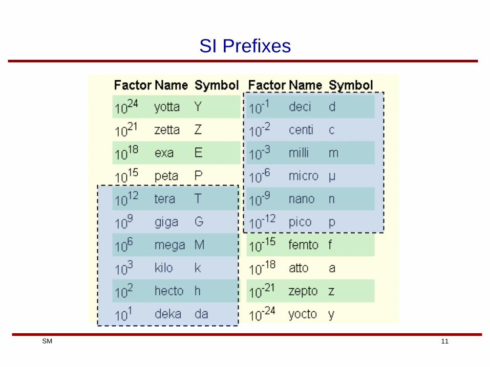
SI Prefixes
12 SM
EECE 251, Set 1
Review of Basic Circuit Concepts
• Electric Charge is the basis for describing all electrical phenomena .
• Charge is an electrical property of the atomic particles of which matter consists and is measured in coulombs (Charles Augustin de Coulomb (1736-1806) a French Scientist)
• Inside an atom, there is negative charge on electrons, positive charge on protons and no charge on neutrons.
• The charge of an electron is equal to that of an proton and is:
e =1.602 10 -19 C
13 SM
EECE 251, Set 1
Charge
• Note that in 1C of charge there are:
1/ 1.602 10 -19 = 6.24 10 18 electrons
• Laboratory values of charges are more likely to be a fraction of a
Coulumb (e.g., pC, nC, mC, or mC).
• Law of conservation of charge: charge can neither be created
nor destroyed, only transferred. (This is a law in classical
physics and may not be true in some odd cases!. We are not
dealing with those cases anyway.)
• Electrical effects are attributed to both separation of charges
and/or charges in motion!
14 SM
EECE 251, Set 1
A Material Classification
• Conductor: a material in which charges can move to
neighboring atoms with relative ease.
– One measure of this relative ease of charge movement is
the electric resistance of the material
– Example conductor material: metals and carbon
– In metals the only charged particles that can move are
electrons
• Insulator: a material that opposes the charge movement
(ideally infinite opposition, i.e., no charge movement)
– Example insulators: Dry air and glass
• Semi-conductor: a material whose conductive properties are
somewhat in between those of conductor and insulator
– Example semi-conductor material: Silicon with some added
impurities
15 SM
EECE 251, Set 1
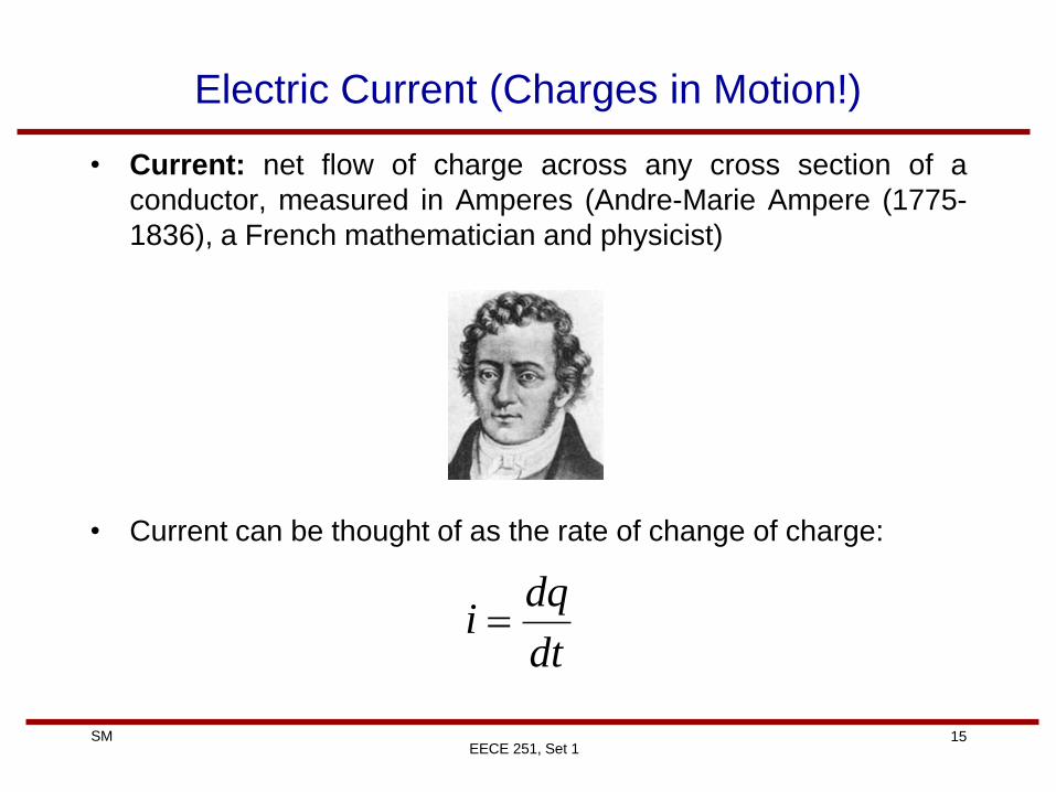
Electric Current (Charges in Motion!)
• Current: net flow of charge across any cross section of a
conductor, measured in Amperes (Andre-Marie Ampere (1775-
1836), a French mathematician and physicist)
• Current can be thought of as the rate of change of charge:
dt
dqi
16 SM
EECE 251, Set 1
Electric Current
• Originally scientists (in particular Benjamin Franklin (1706-1790)
an American scientist and inventor) thought that current is only
due to the movement of positive charges.
• Thus the direction of the current was considered the direction of
movement of positive charges.
current
17 SM
EECE 251, Set 1
Electric Current
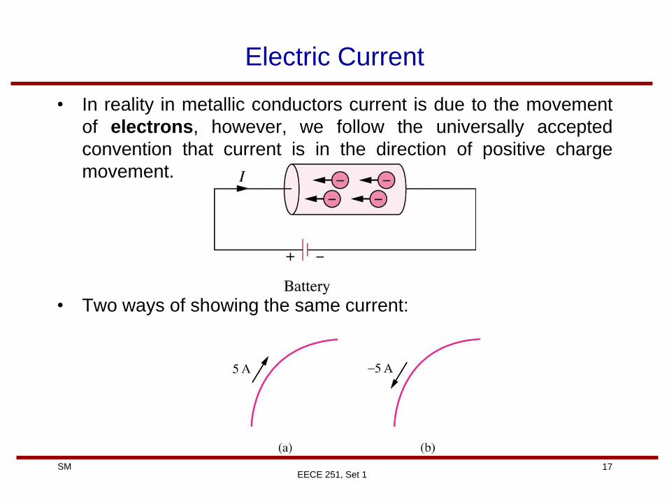
• In reality in metallic conductors current is due to the movement
of electrons, however, we follow the universally accepted
convention that current is in the direction of positive charge
movement.
• Two ways of showing the same current:
18 SM
EECE 251, Set 1
Two Important Types of Current
• Direct current (DC) is a current that remains constant with time.
• Alternating current (AC) is a current that varies sinusoidally with
time.
19 SM
Magnitude of Some Typical Currents
EECE 251, Set 1
20 SM
EECE 251, Set 1
Voltage (Separation of Charge)
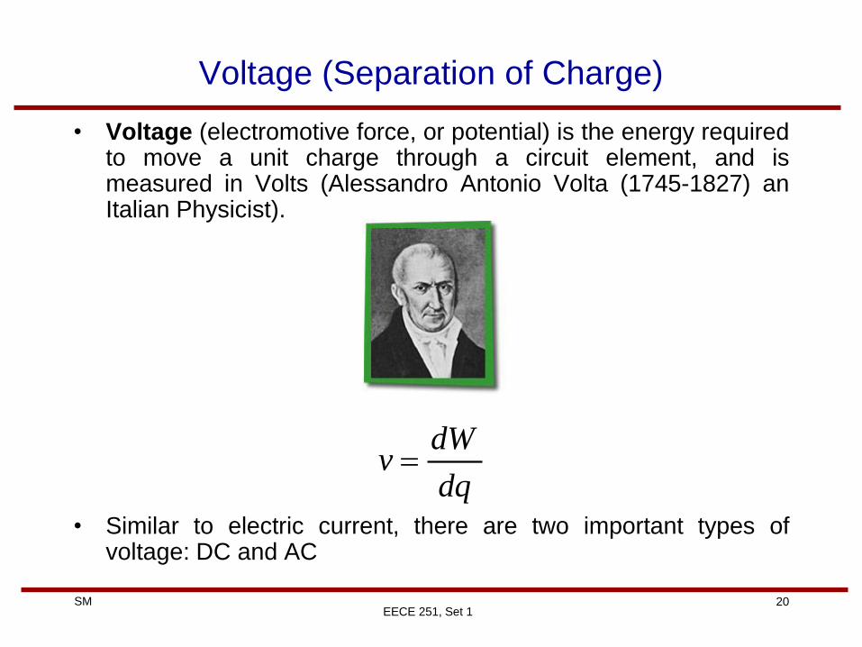
• Voltage (electromotive force, or potential) is the energy required to move a unit charge through a circuit element, and is measured in Volts (Alessandro Antonio Volta (1745-1827) an Italian Physicist).
• Similar to electric current, there are two important types of voltage: DC and AC
dq
dWv
21 SM
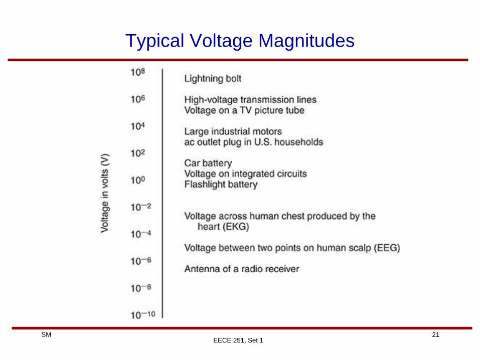
Typical Voltage Magnitudes
EECE 251, Set 1
22 SM
Voltage
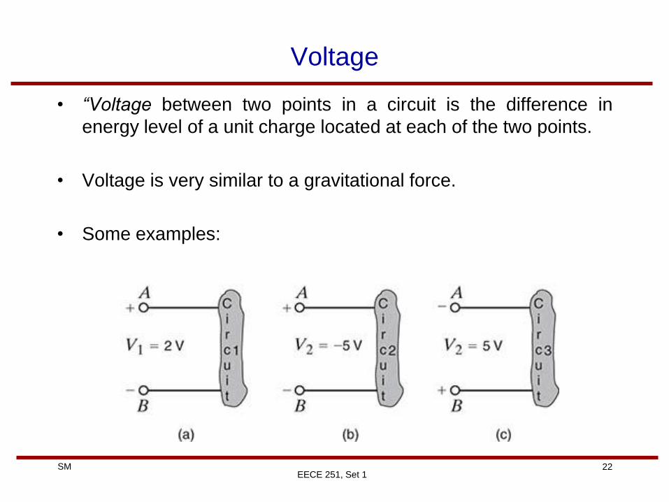
• “Voltage between two points in a circuit is the difference in
energy level of a unit charge located at each of the two points.
• Voltage is very similar to a gravitational force.
• Some examples:
EECE 251, Set 1
23 SM
EECE 251, Set 1
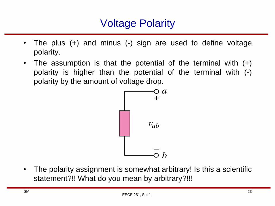
Voltage Polarity
• The plus (+) and minus (-) sign are used to define voltage
polarity.
• The assumption is that the potential of the terminal with (+)
polarity is higher than the potential of the terminal with (-)
polarity by the amount of voltage drop.
• The polarity assignment is somewhat arbitrary! Is this a scientific
statement?!! What do you mean by arbitrary?!!!
24 SM
EECE 251, Set 1
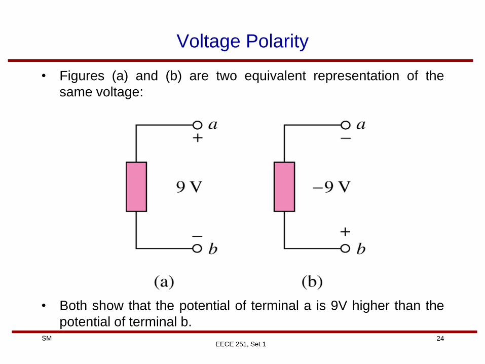
Voltage Polarity
• Figures (a) and (b) are two equivalent representation of the
same voltage:
• Both show that the potential of terminal a is 9V higher than the
potential of terminal b.
25 SM
EECE 251, Set 1
Power
• The rate of change of (expending or absorbing) energy per unit
time, measured in Watts (James Watt (1736-1819) a Scottish
inventor and mechanical engineer)
vidt
dq
dq
dW
dt
dWp
26 SM
A Classification of Circuit Components
• One common classification for circuit components is to group
them in two major groups:
1) Passive components or passive elements
Components or elements that absorb power.
2) Active components or active elements
Components that are not passive! that is, components that
deliver power.
EECE 251, Set 1
27 SM
EECE 251, Set 1
Passive Sign Convention
• For calculating absorbed power: The power absorbed by any
circuit element with terminals A and B is equal to the voltage
drop from A to B multiplied by the current through the element
from A to B, i.e.,
• With this convention if , then the element is absorbing
(consuming) power. Otherwise (i.e., ) is absorbing negative
power or actually generating (delivering) power.
abab IVP
0P0P
a b + -
abV
abI
28 SM
Tellegan’s Theorem
EECE 251, Set 1
• Principle of Conservation of the Power: The algebraic sum of
the powers absorbed by all elements in a circuit is zero at any
instance of time (ΣP=0). That is, the sum of absorbed powers is
equal to the sum of generated powers at each instance of time.
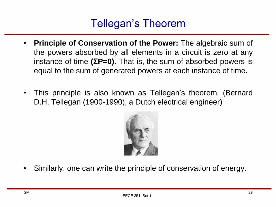
• This principle is also known as Tellegan’s theorem. (Bernard
D.H. Tellegan (1900-1990), a Dutch electrical engineer)
• Similarly, one can write the principle of conservation of energy.
29 SM
EECE 251, Set 1
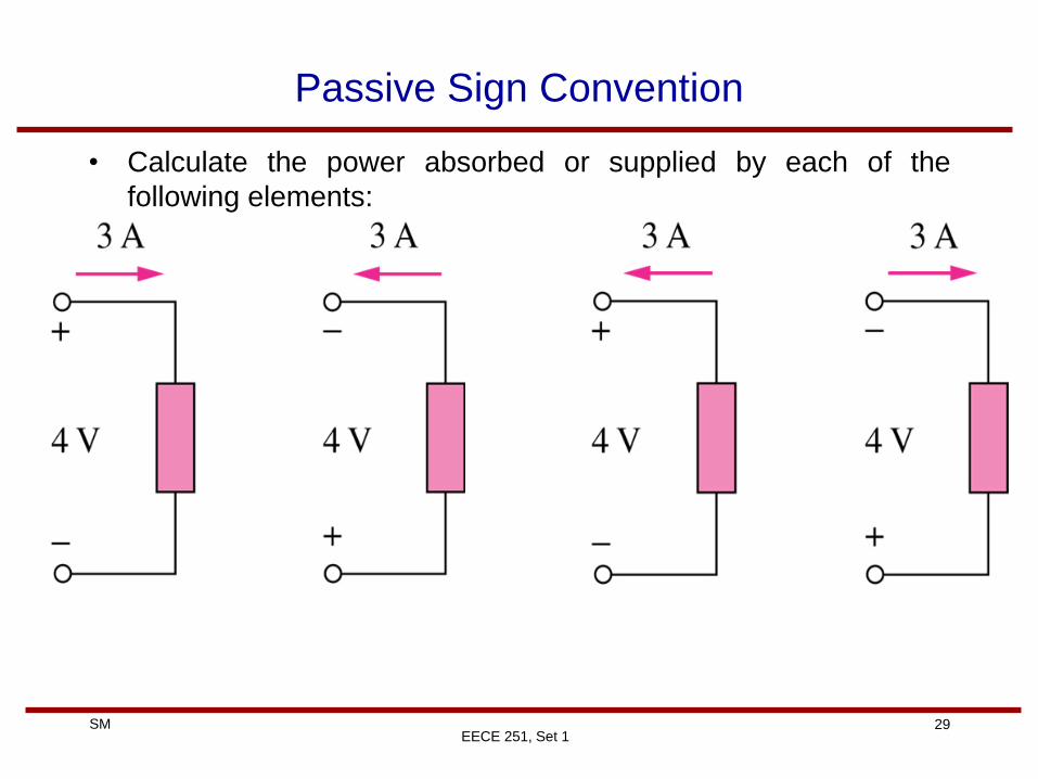
Passive Sign Convention
• Calculate the power absorbed or supplied by each of the
following elements:
30 SM
Example
• Given the two diagrams shown below, determine whether the
element is absorbing or supplying power and how much.
EECE 251, Set 1
31 SM
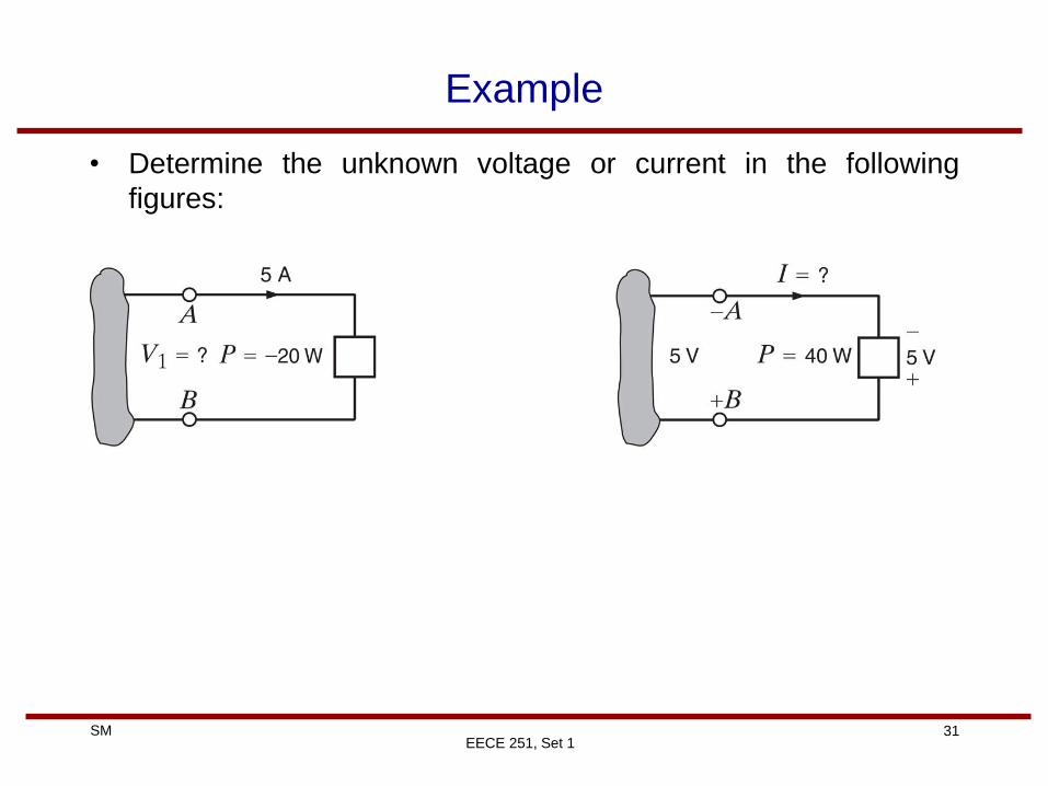
Example
• Determine the unknown voltage or current in the following
figures:
EECE 251, Set 1
32 SM
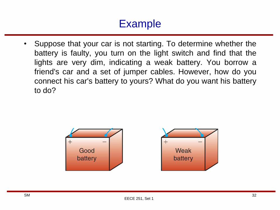
Example
• Suppose that your car is not starting. To determine whether the
battery is faulty, you turn on the light switch and find that the
lights are very dim, indicating a weak battery. You borrow a
friend's car and a set of jumper cables. However, how do you
connect his car's battery to yours? What do you want his battery
to do?
EECE 251, Set 1
33 SM
EECE 251, Set 1
Energy Calculation
• Instantaneous power:
• Energy absorbed or supplied by an element from time t0 to time
t>t0
)()()( titvtp
t
t
t
tdivdpttWW
0 0
)()()(),( 0
Remainder
of Circuit
Circuit element
consuming/generating
power p(t)
+
-
)(tv
)(ti
34 SM
Circuit Elements
• Circuit components can be broadly classified as being either
active or passive.
• An active element is capable of generating energy.
– Example: current or voltage sources
• A passive element is an element that does not generate energy,
however, they can either consume or store energy.
– Example: resistors, capacitors, and inductors
EECE 251, Set 1
35 SM
EECE 251, Set 1
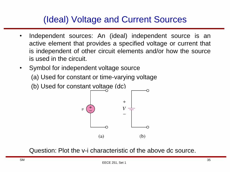
(Ideal) Voltage and Current Sources
• Independent sources: An (ideal) independent source is an
active element that provides a specified voltage or current that
is independent of other circuit elements and/or how the source
is used in the circuit.
• Symbol for independent voltage source
(a) Used for constant or time-varying voltage
(b) Used for constant voltage (dc)
Question: Plot the v-i characteristic of the above dc source.
36 SM
EECE 251, Set 1
Ideal Voltage and Current Sources
• Equivalent representation of ideal independent current sources
whose current i(t) is maintained under all voltage requirements
of the attached circuit:
• What is the equivalent of the ideal voltage source shown on the
previous slide (Figure (a))?
37 SM
EECE 251, Set 1
Common Voltage and Current Source Labeling
• Is this different from passive sign convention?
• Can we use the passive convention for sources
38 SM
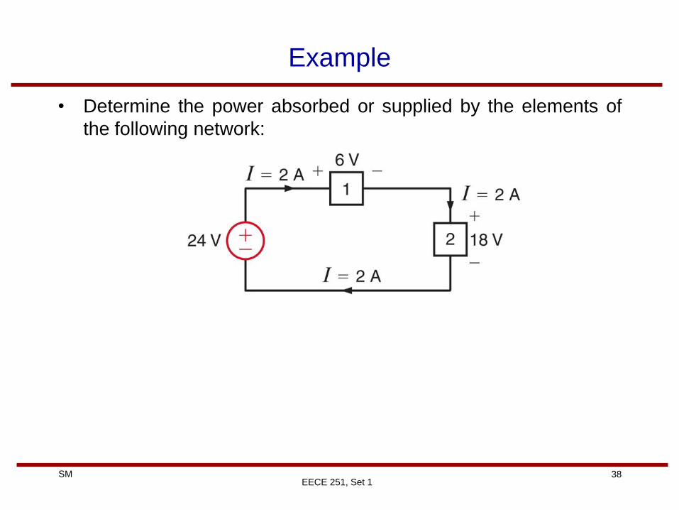
Example
• Determine the power absorbed or supplied by the elements of
the following network:
EECE 251, Set 1
39 SM
EECE 251, Set 1
Ideal Dependent (Controlled) Source
• An ideal dependent (controlled) source is an active element
whose quantity is controlled by a voltage or current of another
circuit element.
• Dependent sources are usually presented by diamond-shaped
symbols:
40 SM
EECE 251, Set 1
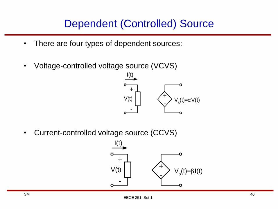
Dependent (Controlled) Source
• There are four types of dependent sources:
• Voltage-controlled voltage source (VCVS)
• Current-controlled voltage source (CCVS)
+-
Vs(t)=V(t)
+
-
V(t)
I(t)
+-
Vs(t)=I(t)
+
-
V(t)
I(t)
41 SM
EECE 251, Set 1
Dependent (Controlled) Source
• Voltage-controlled current source (VCCS)
• Current-controlled current source (CCCS)
Is(t)=V(t)
+
-
V(t)
I(t)
Is(t)=I(t)
+
-
V(t)
I(t)
42 SM
EECE 251, Set 1
Example: Dependent Source
• In the following circuits, identify the type of dependent sources:
43 SM
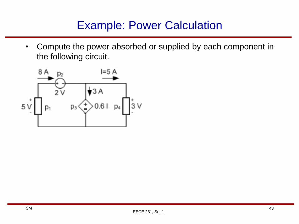
Example: Power Calculation
• Compute the power absorbed or supplied by each component in
the following circuit.
EECE 251, Set 1
44 SM
Example
• Use Tellegan’s theorem to find the current I0 in the following
circuit:
EECE 251, Set 1
45 SM
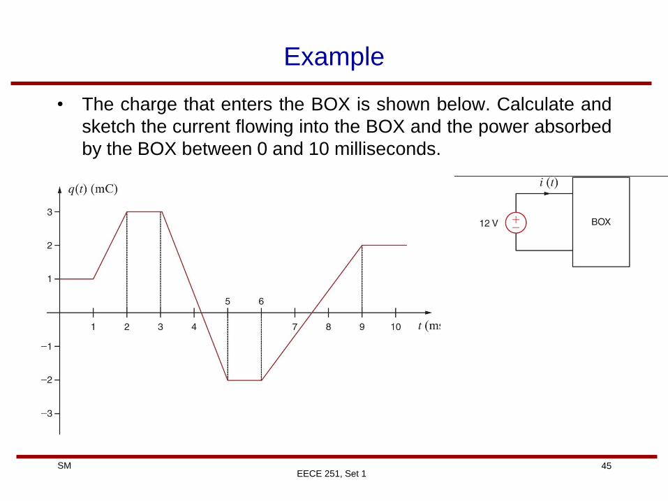
Example
• The charge that enters the BOX is shown below. Calculate and
sketch the current flowing into the BOX and the power absorbed
by the BOX between 0 and 10 milliseconds.
EECE 251, Set 1
46 SM
Notes
EECE 251, Set 1
47 SM
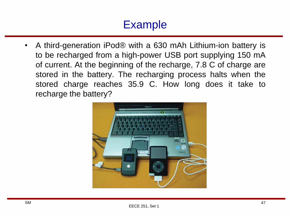
Example
• A third-generation iPod® with a 630 mAh Lithium-ion battery is
to be recharged from a high-power USB port supplying 150 mA
of current. At the beginning of the recharge, 7.8 C of charge are
stored in the battery. The recharging process halts when the
stored charge reaches 35.9 C. How long does it take to
recharge the battery?
EECE 251, Set 1
48 SM
EECE 251, Set 1
Resistance
• Different material allow charges to move within them with
different levels of ease. This physical property or ability to resist
current is known as resistance.
• The resistance of any material with a uniform cross-sectional
area A and length l is inversely proportional to A and directly
proportional to l.
49 SM
EECE 251, Set 1
Resistance
• The constant of the proportionality is the resistivity of the
material, i.e., r
A
lR
A
lR r
50 SM
EECE 251, Set 1
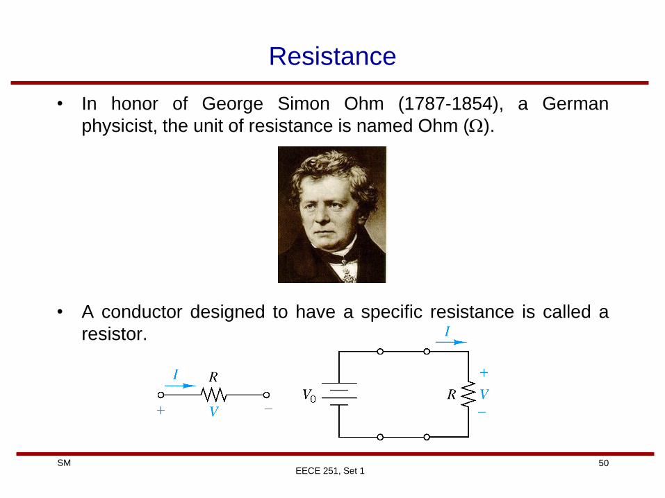
Resistance
• In honor of George Simon Ohm (1787-1854), a German
physicist, the unit of resistance is named Ohm (W).
• A conductor designed to have a specific resistance is called a
resistor.
51 SM
EECE 251, Set 1
Ohm’s Law
• The voltage v across a resistor is directly proportional to the
current i flowing through the resistor. The proportionality
constant is the resistance of the resistor, i.e.,
• One can also write:
• Instantaneous power dissipated in a resistor
)()( tRitv
)()()(1
)( tGvtitvR
ti
)()(
)()()( 22
tRiR
tvtitvtp
52 SM
EECE 251, Set 1
Linear and Nonlinear Resistors
• Linear resistor Nonlinear resistor
• In this course, we assume that all the elements that are
designated as resistors are linear (unless mentioned otherwise)
53 SM
EECE 251, Set 1
Resistors (Fixed and Variable)
• Fixed resistors have a resistance that remains constants.
• Two common type of fixed resistors are:
(a) wirewound
(b) composition (carbon film type)
54 SM
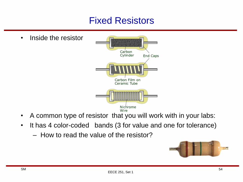
Fixed Resistors
• Inside the resistor
• A common type of resistor that you will work with in your labs:
• It has 4 color-coded bands (3 for value and one for tolerance)
– How to read the value of the resistor?
EECE 251, Set 1
55 SM
EECE 251, Set 1
Variable Resistors
• Variable resistors have adjustable resistance and are typically
called potentiometer (or pot for short).
• Potentiometers have three terminals one of which is a sliding
contact or wiper.
56 SM
EECE 251, Set 1
Conductance
• G=1/R is called the conductance of the element and is
measured in siemens (S) or mho ( ) .
German inventor
Ernst Werner von Siemens
(1816-1892)
• Conductance is the ability of an element to conduct current..
• A device with zero (no) resistance has infinite conductance and
a device with infinite resistance has zero conductance.
W
57 SM
EECE 251, Set 1
Short and Open Circuits
• A device with zero resistance is called short circuit and a device
with zero conductance (i.e., infinite resistance) is called open-
circuit.
58 SM
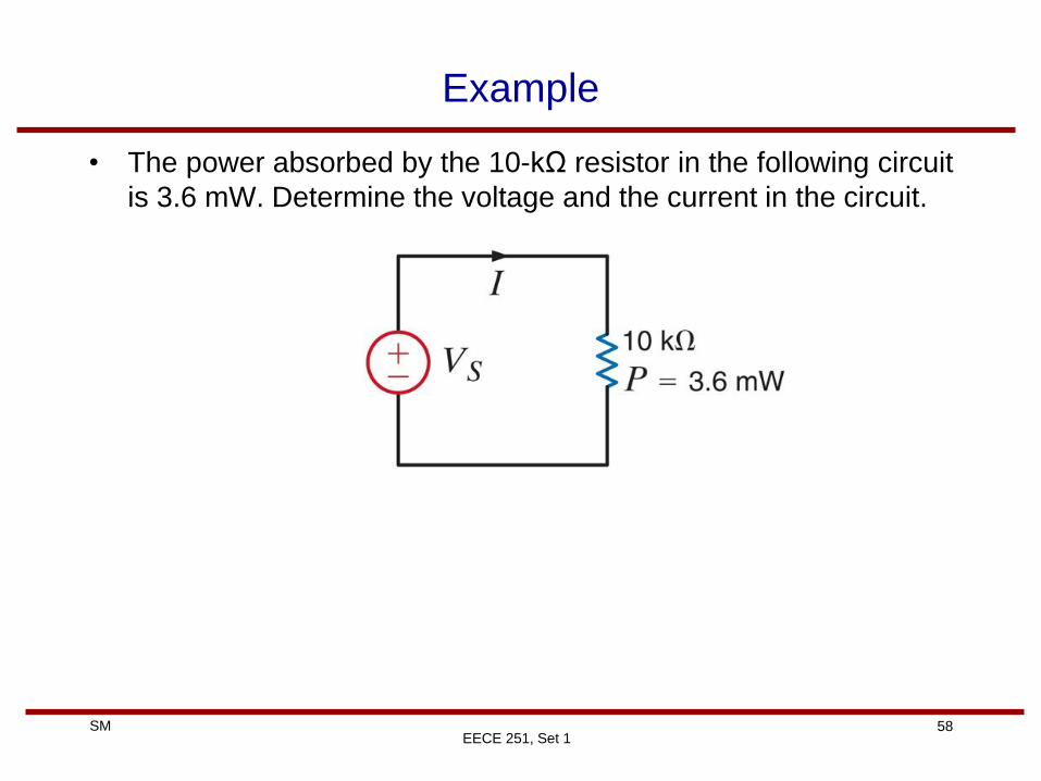
Example
• The power absorbed by the 10-kΩ resistor in the following circuit
is 3.6 mW. Determine the voltage and the current in the circuit.
EECE 251, Set 1
59 SM
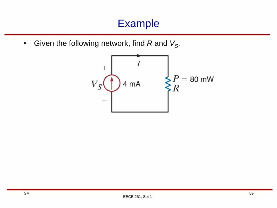
Example
• Given the following network, find R and VS.
EECE 251, Set 1
60 SM
Example
• Given the following circuit, find the value of the voltage source
and the power absorbed by the resistance.
EECE 251, Set 1
61 SM
Wheatstone Bridge
• A Wheatstone Bridge circuit is an accurate device for measuring
resistance. The circuit, shown below, is used to measure the
unknown resistor Rx. The center leg of the circuit contains a
galvanometer (a very sensitive device used to measure current).
When the unknown resistor is connected to the bridge, R3 is
adjusted until the current in the galvanometer is zero, at which
point the bridge is balanced.
EECE 251, Set 1
62 SM
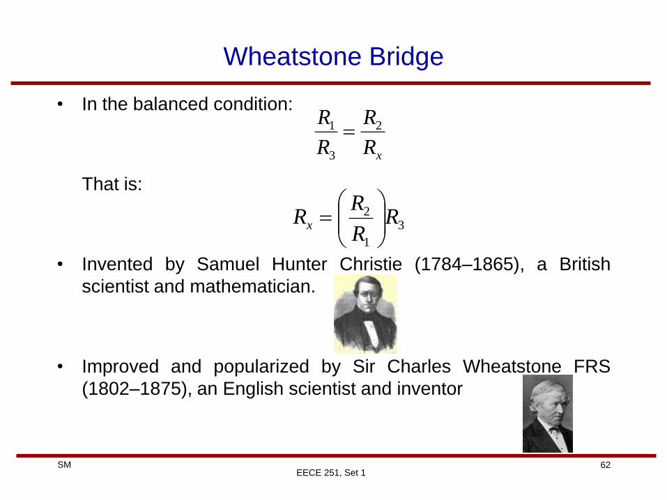
Wheatstone Bridge
• In the balanced condition:
That is:
• Invented by Samuel Hunter Christie (1784–1865), a British
scientist and mathematician.
• Improved and popularized by Sir Charles Wheatstone FRS
(1802–1875), an English scientist and inventor
EECE 251, Set 1
xR
R
R
R 2
3
1
3
1
2 RR
RRx
63 SM
Wheatstone Bridge
• Engineers use the Wheatstone bridge circuit to measure strain
in solid material. For example, in a system used to determine
the weight of a truck (shown below). The platform is supported
by cylinders on which strain gauges are mounted. The strain
gauges, which measure strain when the cylinder deflects under
load, are connected to a Wheatstone bridge.
EECE 251, Set 1
64 SM
Wheatstone Bridge
• Typically, the strain gauge has a resistance of 120Ω under
no-load conditions and changes value under load. The variable
resistor in the bridge is a calibrated precision device.
EECE 251, Set 1
65 SM
Terminology (Nodes and Branches)
• Note: our definition of nodes (and branches) is slightly different
from traditional definitions used in the textbooks!
• Please note that almost all components that we deal with in this
course are two-terminal components (resistors, sources, …)
• A “true node” (or node for short) is the point of connection of
three or more circuit elements. (The node includes the
interconnection wires.)
• A “binary node” (or b-node for short) has only two components
connected to it.
EECE 251, Set 1
66 SM
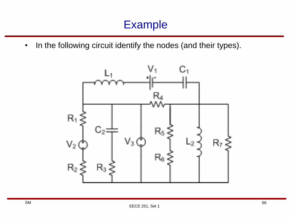
Example
• In the following circuit identify the nodes (and their types).
EECE 251, Set 1
67 SM
Example
• Are the following two circuits different? Identify the nodes (and
their types) in each circuit.
EECE 251, Set 1
68 SM
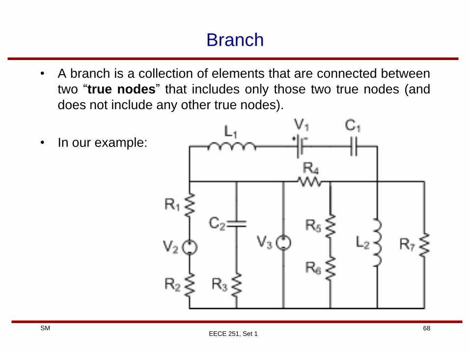
Branch
• A branch is a collection of elements that are connected between
two “true nodes” that includes only those two true nodes (and
does not include any other true nodes).
• In our example:
EECE 251, Set 1
69 SM
Loop
• A “loop” is any closed path in the circuit that does not cross any
true node but once.
• A “window pane loop” is a loop that does not contain any other
loops inside it.
• An “independent loop” is a loop that contains at least one
branch that is not part of any other independent loop.
EECE 251, Set 1
70 SM
EECE 251, Set 1
Example
• In the following circuit, find the number of branches, nodes, and
window pane loops. Are the window pane loops independent?
71 SM
EECE 251, Set 1
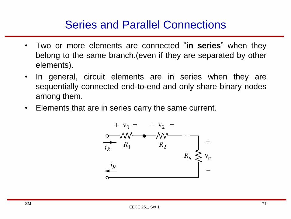
Series and Parallel Connections
• Two or more elements are connected “in series” when they
belong to the same branch.(even if they are separated by other
elements).
• In general, circuit elements are in series when they are
sequentially connected end-to-end and only share binary nodes
among them.
• Elements that are in series carry the same current.
72 SM
EECE 251, Set 1
Series and Parallel Circuits
• Two or more circuit elements are “in parallel” if they are
connected between the same two “true nodes”.
• Consequently, parallel elements have the same voltage
73 SM
EECE 251, Set 1
Kirchhoff’s Current Law (KCL)
• Gustav Robert Kirchhoff (1824-1887), a German physicist,
stated two basic laws concerning the relationship between the
currents and voltages in an electrical circuit.
• KCL: The algebraic sum of the currents entering a node (or a
closed boundary) is zero.
• The current entering a node may be regarded as positive while
the currents leaving the node may be taken as negative or vice
versa.
74 SM
EECE 251, Set 1
KCL
• KCL is based on the law of conservation of charge.
• Example: Write the KCL for the node A inside this black box
circuit:
i4
i3 i2
i1
Black box circuit
A
75 SM
EECE 251, Set 1
KCL
• Alternative statement of KCL: For lumped circuits, the
algebraic sum of the currents leaving a node (or a closed
boundary) is zero.
•
The sum of the currents entering a node is equal to the sum of
the currents leaving that node.
Σiin=Σiout
Can you think of another statement for KCL?
76 SM
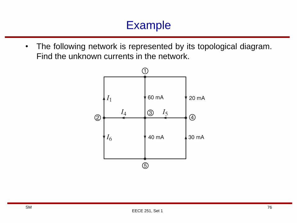
Example
• The following network is represented by its topological diagram.
Find the unknown currents in the network.
EECE 251, Set 1
77 SM
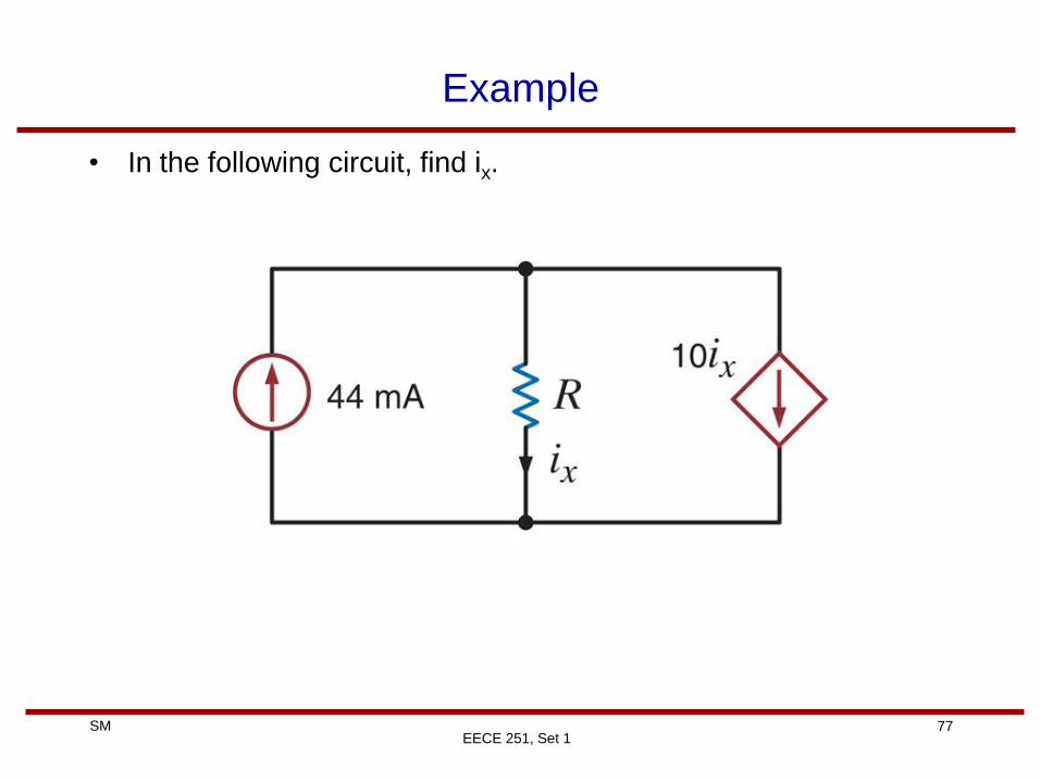
Example
• In the following circuit, find ix.
EECE 251, Set 1
78 SM
EECE 251, Set 1
Closed Boundary
• A closed boundary is a closed curve (or surface), such as a
circle in a plane (or a sphere in three dimensional space) that
has a well-defined inside and outside.
• This closed boundary is sometimes called supernode or more
formally a Gauss surface.
• Johann Carl Friedrich Gauss
(1777-1855)
German mathematician
79 SM
EECE 251, Set 1
KCL Example
• Draw an appropriate closed boundary to find I in the following
graphical circuit representation.
2A
3A
I
80 SM
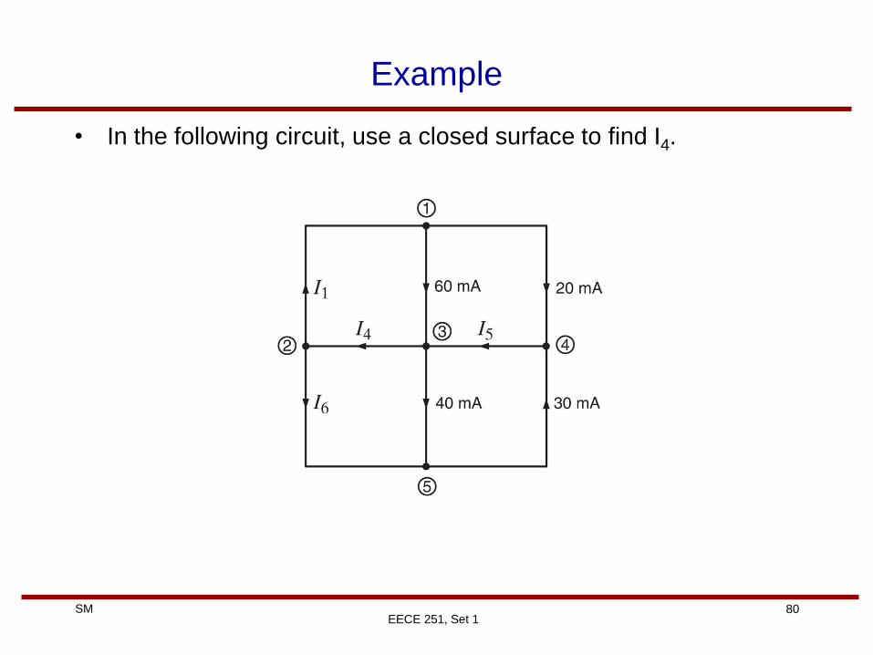
Example
• In the following circuit, use a closed surface to find I4.
EECE 251, Set 1
81 SM
EECE 251, Set 1
Kirchhoff’s Voltage Law (KVL)
• KVL: The algebraic sum of the voltage drops around any closed path (or loop) is zero at any instance of time.
• Write KVL for the above circuit.
Sum of voltage drops=Sum of voltage rises
82 SM
EECE 251, Set 1
KVL Example
• Find VAC and VCH in the following circuit.
-2V
A
B
C
D E
G
F
H
+
+
+
-
-
-
-
2V
1V
+
4V
83 SM
EECE 251, Set 1
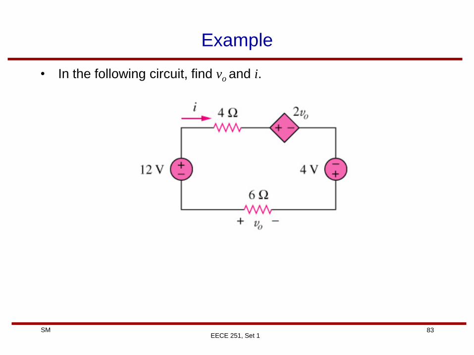
Example
• In the following circuit, find vo and i.
84 SM
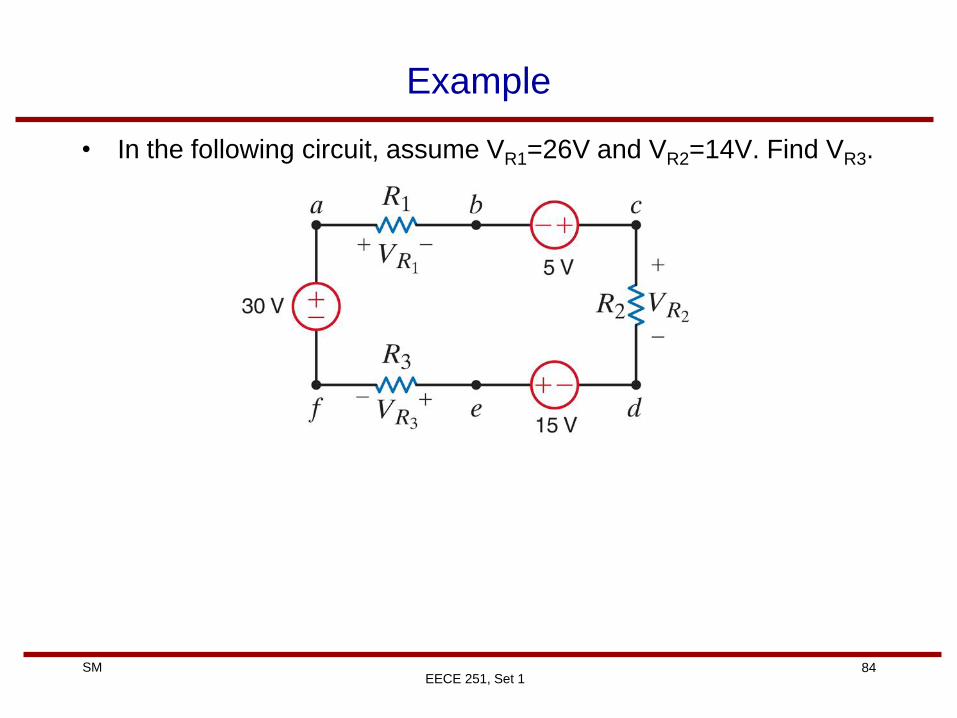
Example
• In the following circuit, assume VR1=26V and VR2=14V. Find VR3.
EECE 251, Set 1
85 SM
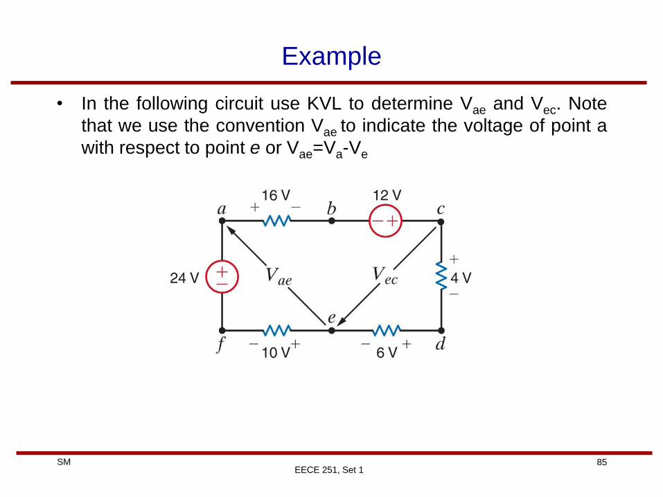
Example
• In the following circuit use KVL to determine Vae and Vec. Note
that we use the convention Vae to indicate the voltage of point a
with respect to point e or Vae=Va-Ve
EECE 251, Set 1
86 SM
EECE 251, Set 1
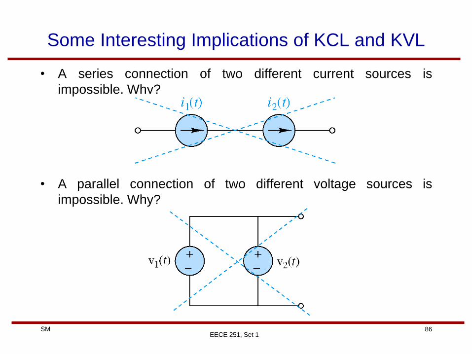
Some Interesting Implications of KCL and KVL
• A series connection of two different current sources is
impossible. Why?
• A parallel connection of two different voltage sources is
impossible. Why?
87 SM
EECE 251, Set 1
More Interesting Implicationsz
• A current source supplying zero current is equivalent to an open
circuit:
• A voltage source supplying 0V is equivalent to a short circuit:
88 SM
EECE 251, Set 1
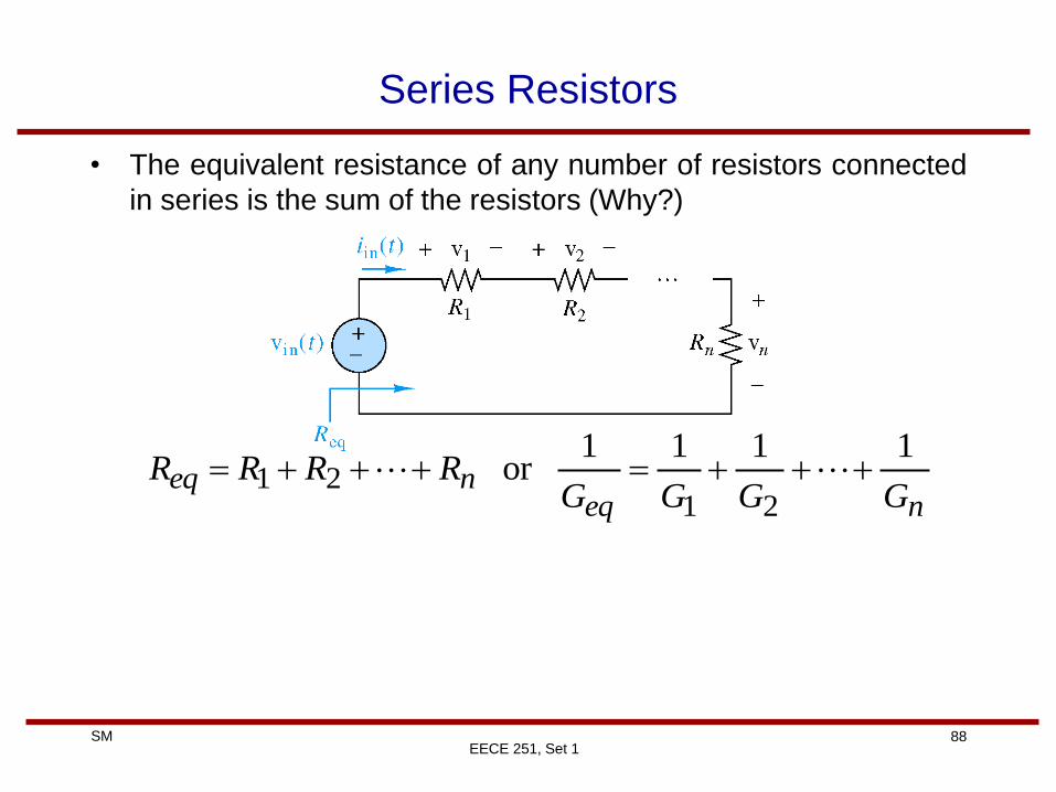
Series Resistors
• The equivalent resistance of any number of resistors connected
in series is the sum of the resistors (Why?)
neqneq
GGGGRRRR
1111or
2121
89 SM
EECE 251, Set 1
Voltage Division
• In a series combination of n resistors, the voltage drop across
the resistor Rj for j=1,2, …, n is:
• What is the formula for two series resistors?!
)()(21
tvRRR
Rtv in
n
j
j
90 SM
EECE 251, Set 1
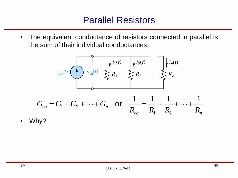
Parallel Resistors
• The equivalent conductance of resistors connected in parallel is
the sum of their individual conductances:
• Why?
neq
neqRRRR
GGGG1111
21
21 or
91 SM
EECE 251, Set 1
Current Division
• In a parallel combination of n resistors, the current through the
resistor Rj for j=1,2, …, n is:
• Why?
)()(21
tiGGG
Gti in
n
j
j
92 SM
EECE 251, Set 1
Parallel Resistors and Current Division Example
• For the special case of two parallel resistors
• Why?
)()(),()(,21
12
21
21
21
21 tiRR
Rtiti
RR
Rti
RR
RRReq
and
93 SM
EECE 251, Set 1
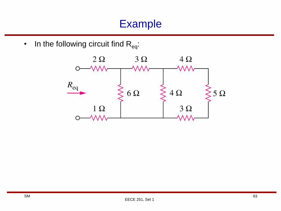
Example
• In the following circuit find Req:
94 SM
Example
• In the following circuit find the resistance seen between the two
terminal s A and B, i.e., RAB
•
EECE 251, Set 1
95 SM
EECE 251, Set 1
Example
• In the following circuit find the current i.
20W
12V
30
W
30
W
30
W
10
W
i
96 SM
Example
• In the following circuit find I1, I2, I3, Va, and Vb.
EECE 251, Set 1
97 SM
EECE 251, Set 1
Tricky Example!
• In the following circuit, find the equivalent resistance Req.
Assume gm=0.5S.
2W
W
1W
Req
+ v1 -
gmv1
98 SM
Standard Resistor Values for 5% and 10% Tolerances
EECE 251, Set 1
99 SM
Example
• Given the network shown in Fig. 2.31: (a) find the required value
for the resistor R; (b) use Table 2.1 to select a standard 10%
tolerance resistor for R; (c) using the resistor selected in (b),
determine the voltage across the 3.9-kΩ resistor; (d) calculate
the percent error in the voltage V1, if the standard resistor
selected in (b) is used; and (e) determine the power rating for
this standard component.
EECE 251, Set 1
100 SM
Board Notes
EECE 251, Set 1
101 SM
EECE 251, Set 1
Wye-Delta Transformations
• In some circuits the resistors are neither in series nor in parallel.
• For example consider the following bridge circuit:
how can we combine the resistors R1 through R6?
102 SM
EECE 251, Set 1
Wye and Delta Networks
• A useful technique that can be used to simply many such
circuits is transformation from wye (Y) to delta (D) network.
• A wye (Y) or tee (T) network is a three-terminal network with the
following general form:
103 SM
EECE 251, Set 1
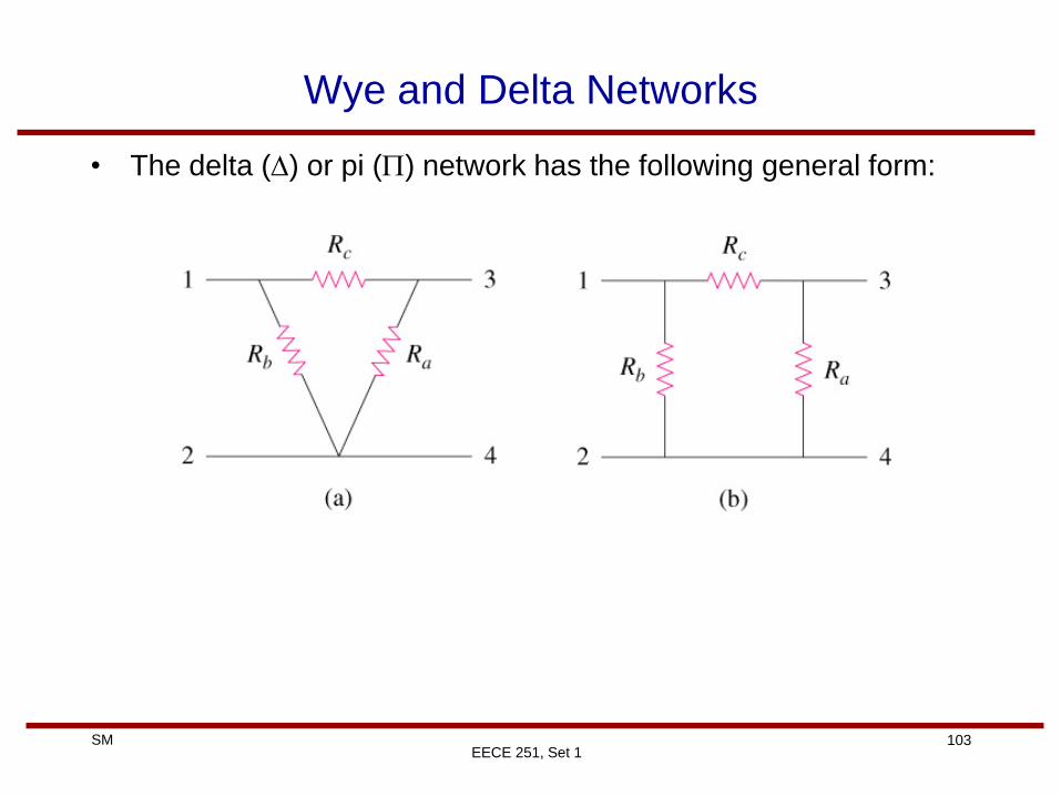
Wye and Delta Networks
• The delta (D) or pi (P) network has the following general form:
104 SM
EECE 251, Set 1
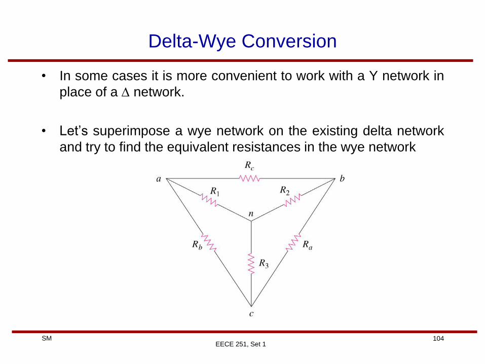
Delta-Wye Conversion
• In some cases it is more convenient to work with a Y network in
place of a D network.
• Let’s superimpose a wye network on the existing delta network
and try to find the equivalent resistances in the wye network
105 SM
EECE 251, Set 1
Delta-Wye Conversion
• We calculate the equivalent resistance between terminals a and
c while terminal b is open in both cases:
Similarly:
cba
cabacac
cabac
ac
RRR
RRRRRRYR
RRRR
RRYR
D
D
)()()(
)()(
)(
31
31
cba
cba
cba
bac
RRR
RRRRR
RRR
RRRRR
)(
)(
32
21
106 SM
EECE 251, Set 1
Delta-Wye Conversion
• Solving for R1, R2, and R3 we have:
• Each resistor in the Y network is the product if the resistors in
the two adjacent D branches, divided by the sum of the three D
resistors.
cba
ba
cba
ac
cba
cb
RRR
RRR
RRR
RRR
RRR
RRR
3
2
1
107 SM
EECE 251, Set 1
Wye-Delta Conversion
• From the previous page equations, we have:
• Dividing this equation by each of the previous slide equations:
• Each resistor in the D network is the sum of all the possible products of Y resistors taken two at a time, divided by the opposite Y resistor
cba
cba
cba
cbacba
RRR
RRR
RRR
RRRRRRRRRRRR
2133221)(
)(
3
133221
2
133221
1
133221 ,,R
RRRRRRR
R
RRRRRRR
R
RRRRRRR cba
and
108 SM
EECE 251, Set 1
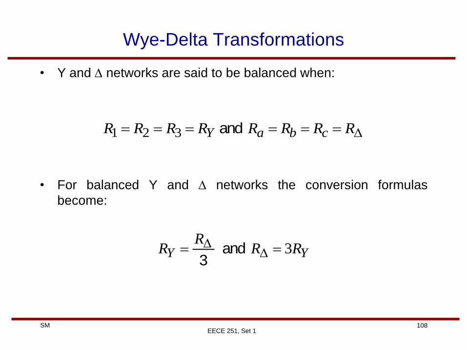
Wye-Delta Transformations
• Y and D networks are said to be balanced when:
• For balanced Y and D networks the conversion formulas
become:
D RRRRRRRR cbaY and 321
YY RRR
R 3 DD and 3
109 SM
EECE 251, Set 1
Example
• For the following bridge network find Rab and i.