Page 1
1 SM
EECE 251, Set 5
EECE251
Circuit Analysis I
Set 5: Operational Amplifiers
Shahriar Mirabbasi
Department of Electrical and Computer Engineering
University of British Columbia
[email protected]
Page 2
2 SM
EECE 251, Set 5
Amplifiers
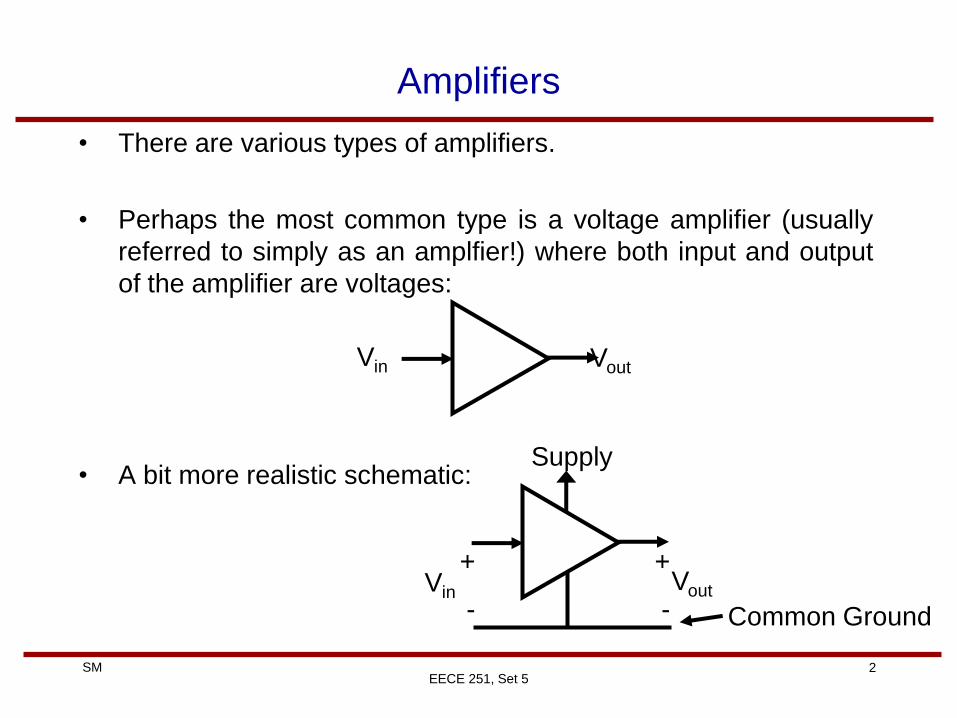
• There are various types of amplifiers.
• Perhaps the most common type is a voltage amplifier (usually
referred to simply as an amplfier!) where both input and output
of the amplifier are voltages:
• A bit more realistic schematic:
Vin Vout
Vin Vout
Supply
+
-
+
-
Common Ground
Page 3
3 SM
Amplifiers
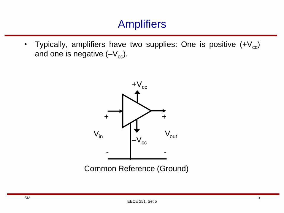
• Typically, amplifiers have two supplies: One is positive (+Vcc)
and one is negative (–Vcc).
EECE 251, Set 5
Vin Vout
+Vcc
+
-
+
-
Common Reference (Ground)
–Vcc
Page 4
4 SM
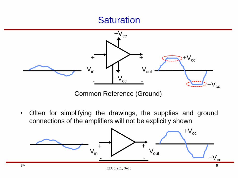
Saturation
• A practical limitation for amplifiers (at least the ones that we will
see in this course) is that the magnitude of their output voltage
cannot exceed the supply, that is:
–Vcc ≤ Vout ≤ +Vcc
• If the output wants to go beyond the supplies (for example when
the input is positive and large) then it will be clipped at +Vcc :
Vout = +Vcc
• If the output is so negative then it will be limited by –Vcc:
Vout = –Vcc
• In these cases we say that the amplifier is saturated
EECE 251, Set 5
Page 5
5 SM
Saturation
• Often for simplifying the drawings, the supplies and ground
connections of the amplifiers will not be explicitly shown
EECE 251, Set 5
Vin Vout
+Vcc
+
-
+
-
Common Reference (Ground)
–Vcc
Vin Vout
+
-
+
-
+Vcc
–Vcc
+Vcc
–Vcc
Page 6
6 SM
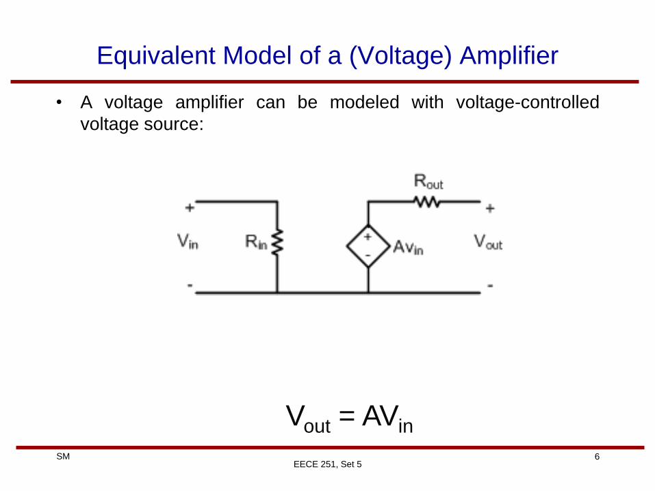
Equivalent Model of a (Voltage) Amplifier
• A voltage amplifier can be modeled with voltage-controlled
voltage source:
EECE 251, Set 5
Vout = AVin
Page 7
7 SM
EECE 251, Set 5
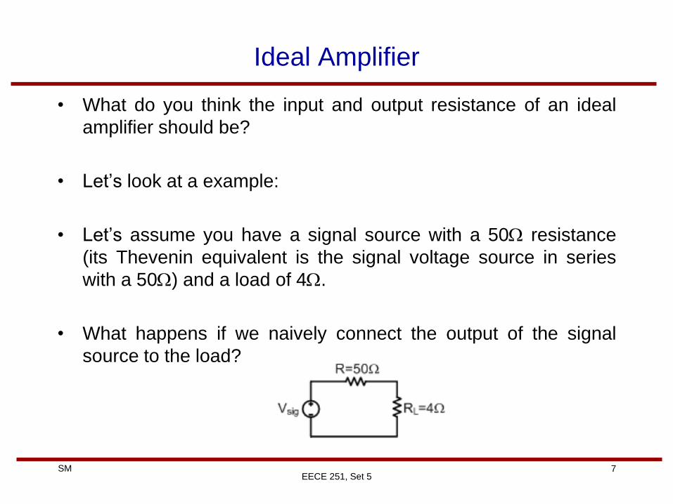
Ideal Amplifier
• What do you think the input and output resistance of an ideal
amplifier should be?
• Let’s look at a example:
• Let’s assume you have a signal source with a 50 resistance
(its Thevenin equivalent is the signal voltage source in series
with a 50) and a load of 4.
• What happens if we naively connect the output of the signal
source to the load?
Page 8
8 SM
EECE 251, Set 5
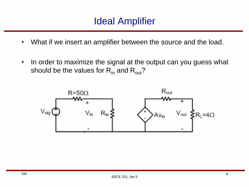
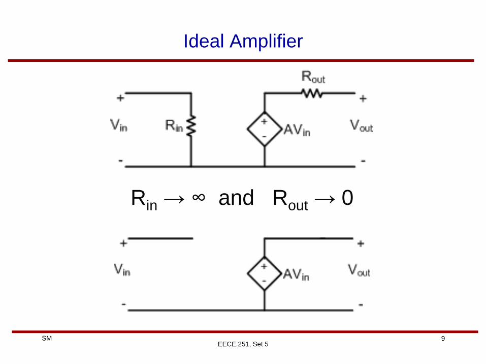
Ideal Amplifier
• What if we insert an amplifier between the source and the load.
• In order to maximize the signal at the output can you guess what
should be the values for Rin and Rout?
Page 9
9 SM
EECE 251, Set 5
Ideal Amplifier
Rin → ∞ and Rout → 0
Page 10
10 SM
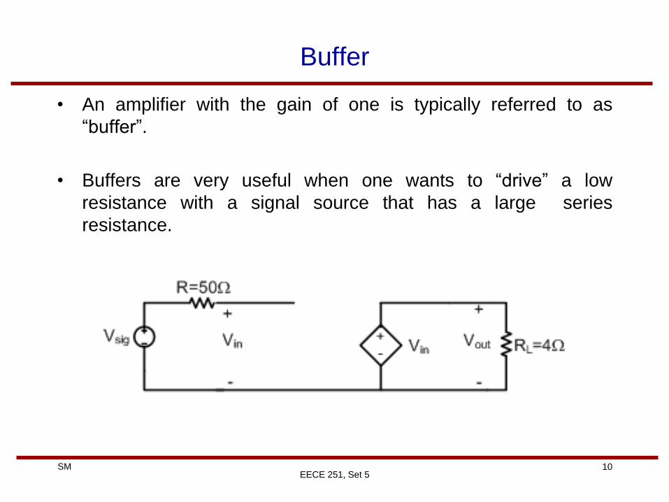
Buffer
• An amplifier with the gain of one is typically referred to as
“buffer”.
• Buffers are very useful when one wants to “drive” a low
resistance with a signal source that has a large series
resistance.
EECE 251, Set 5
Page 11
11 SM
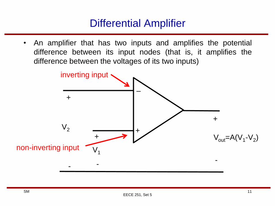
Differential Amplifier
• An amplifier that has two inputs and amplifies the potential
difference between its input nodes (that is, it amplifies the
difference between the voltages of its two inputs)
EECE 251, Set 5
–
+ Vout=A(V1-V2)
+
-
+
-
V2
+
-
V1
inverting input
non-inverting input
Page 12
12 SM
EECE 251, Set 5
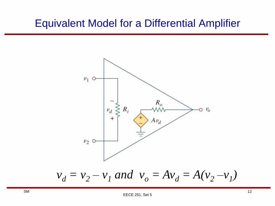
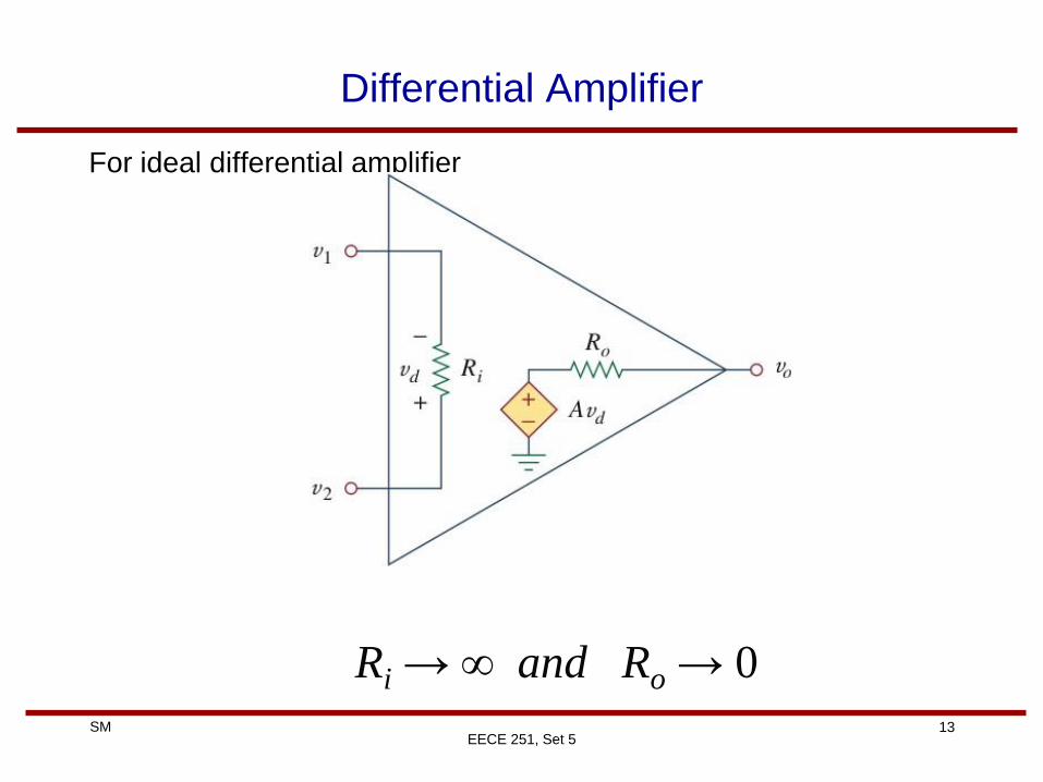
Equivalent Model for a Differential Amplifier
vd = v2 – v1 and vo = Avd = A(v2 –v1)
Page 13
13 SM
EECE 251, Set 5
Differential Amplifier
For ideal differential amplifier
Ri → ∞ and Ro → 0
Page 14
14 SM
EECE 251, Set 5
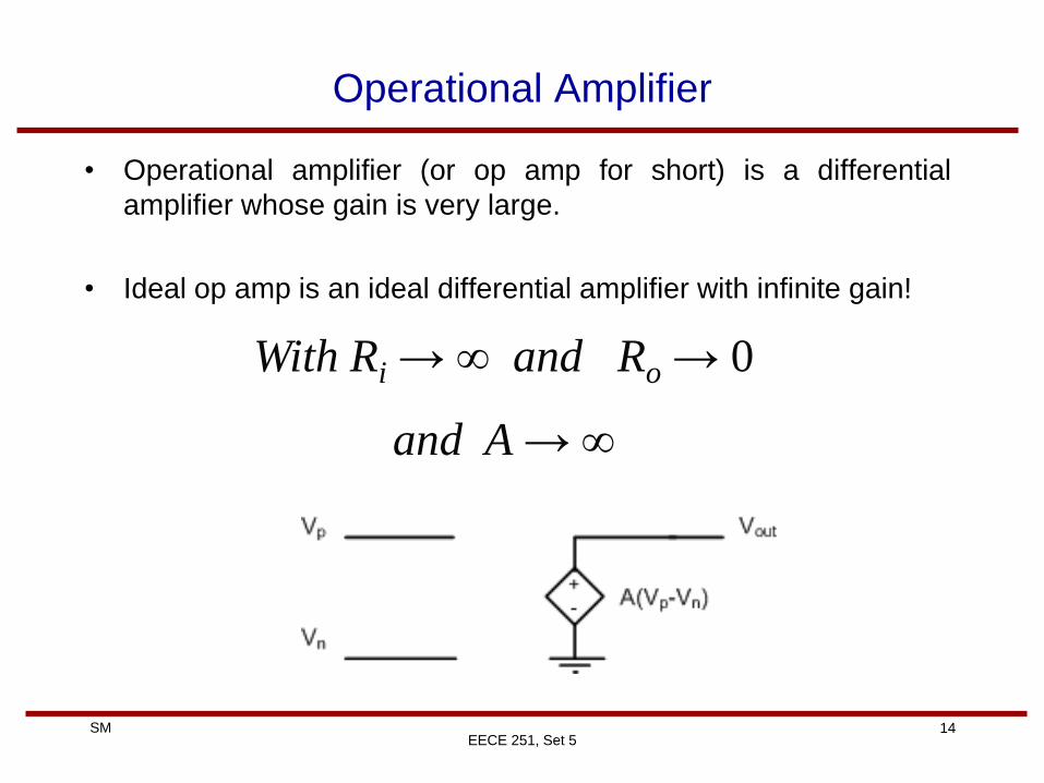
Operational Amplifier
• Operational amplifier (or op amp for short) is a differential
amplifier whose gain is very large.
• Ideal op amp is an ideal differential amplifier with infinite gain!
With Ri → ∞ and Ro → 0
and A → ∞
Page 15
15 SM
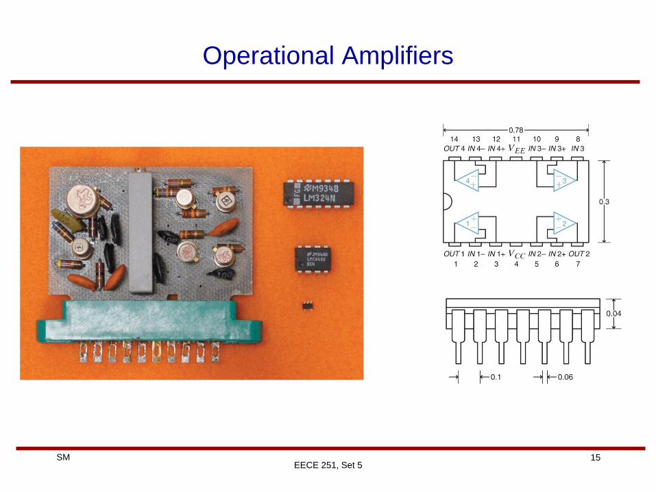
Operational Amplifiers
EECE 251, Set 5
Page 16
16 SM
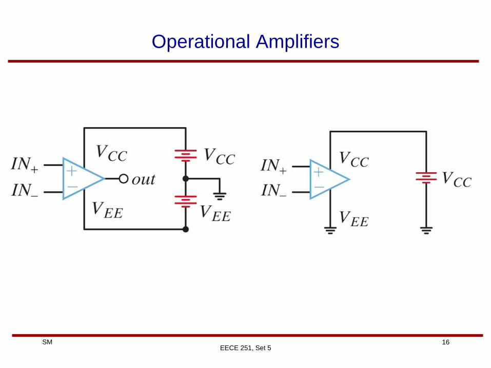
Operational Amplifiers
EECE 251, Set 5
Page 17
17 SM
EECE 251, Set 5
Operational Amplifiers (Op Amps)
• In light of their large gain, op amps are usually used in a
negative feedback configuration where their output is somehow
(usually through a passive component) is connected to their
negative (inverting) input.
• If there is no feedback, what do you expect the output will be?
• In practice, If Vp > Vn then the output will be saturated to the
positive supply. Why?
• And, if Vp < Vn then the output will be saturated to the negative
supply
Page 18
18 SM
EECE 251, Set 5
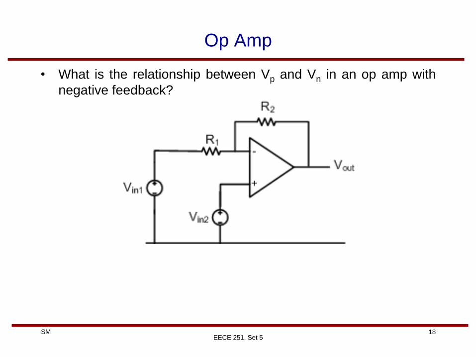
Op Amp
• What is the relationship between Vp and Vn in an op amp with
negative feedback?
Page 19
19 SM
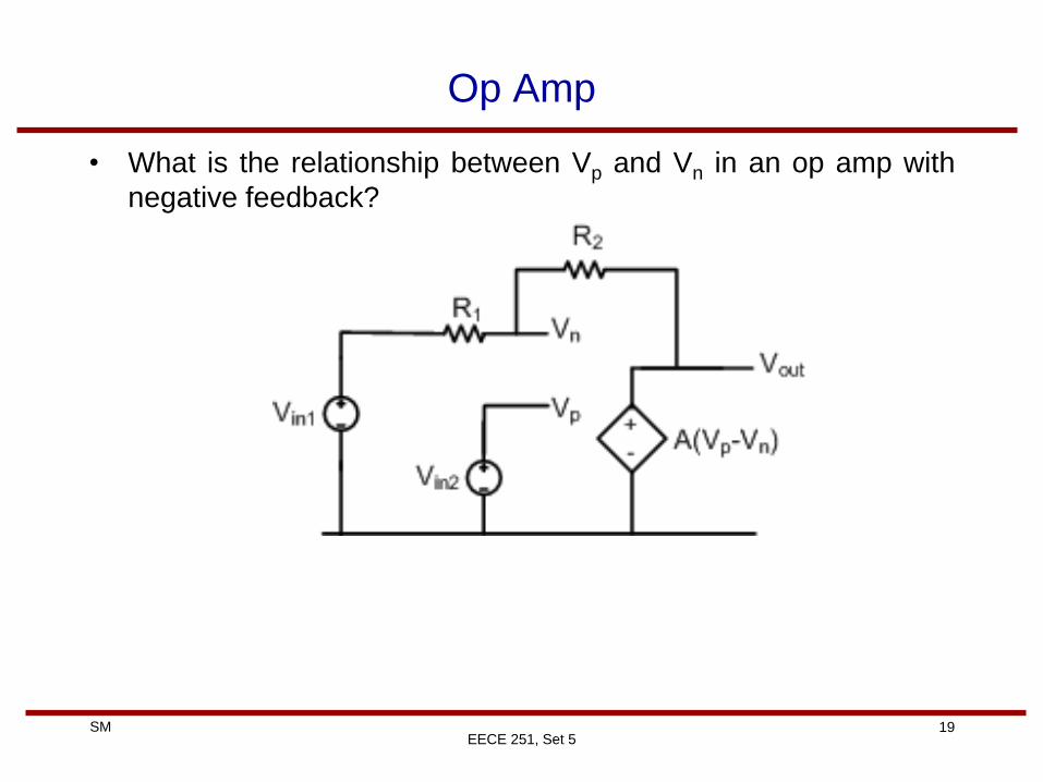
Op Amp
• What is the relationship between Vp and Vn in an op amp with
negative feedback?
EECE 251, Set 5
Page 20
20 SM
Op Amps
• Op amps were designed to performed mathematical operations
such as subtraction, addition, multiplication, division, integration,
and differentiation (therefore the name operational amplifier!).
• So let’s have a look at how we can perform these operations
using op amps.
• Note that in all these cases we should make sure that we have a
negative feedback. Why?
EECE 251, Set 5
Page 21
21 SM
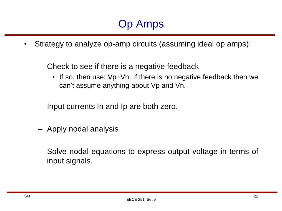
Op Amps
• Strategy to analyze op-amp circuits (assuming ideal op amps):
– Check to see if there is a negative feedback
• If so, then use: Vp=Vn. If there is no negative feedback then we
can’t assume anything about Vp and Vn.
– Input currents In and Ip are both zero.
– Apply nodal analysis
– Solve nodal equations to express output voltage in terms of
input signals.
EECE 251, Set 5
Page 22
22 SM
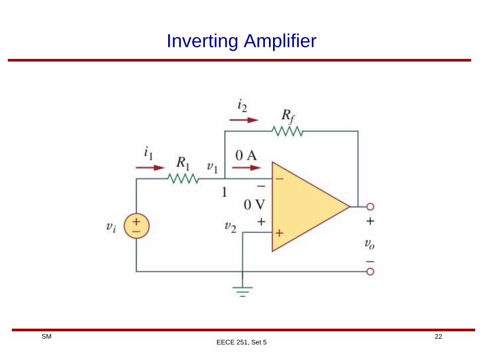
Inverting Amplifier
EECE 251, Set 5
Page 23
23 SM
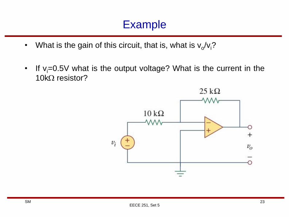
Example
• What is the gain of this circuit, that is, what is vo/vi?
• If vi=0.5V what is the output voltage? What is the current in the
10k resistor?
EECE 251, Set 5
Page 24
24 SM
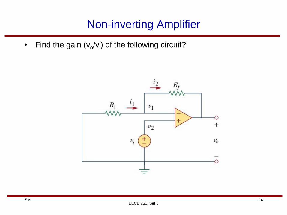
Non-inverting Amplifier
• Find the gain (vo/vi) of the following circuit?
EECE 251, Set 5
Page 25
25 SM
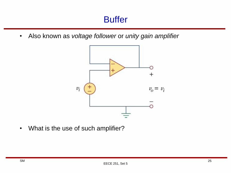
Buffer
• Also known as voltage follower or unity gain amplifier
• What is the use of such amplifier?
EECE 251, Set 5
Page 26
26 SM
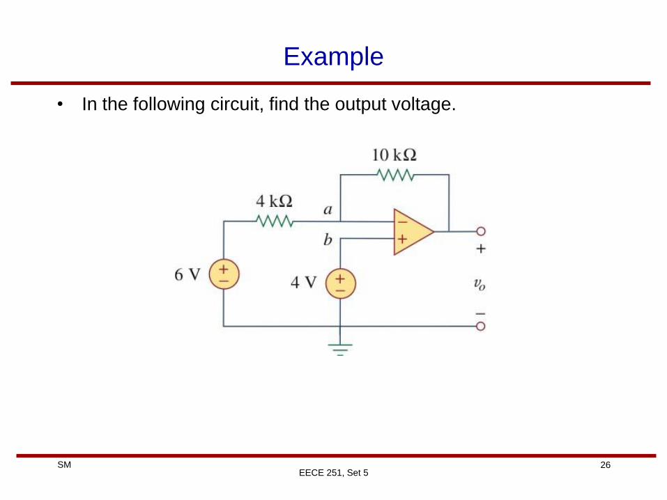
Example
• In the following circuit, find the output voltage.
EECE 251, Set 5
Page 27
27 SM
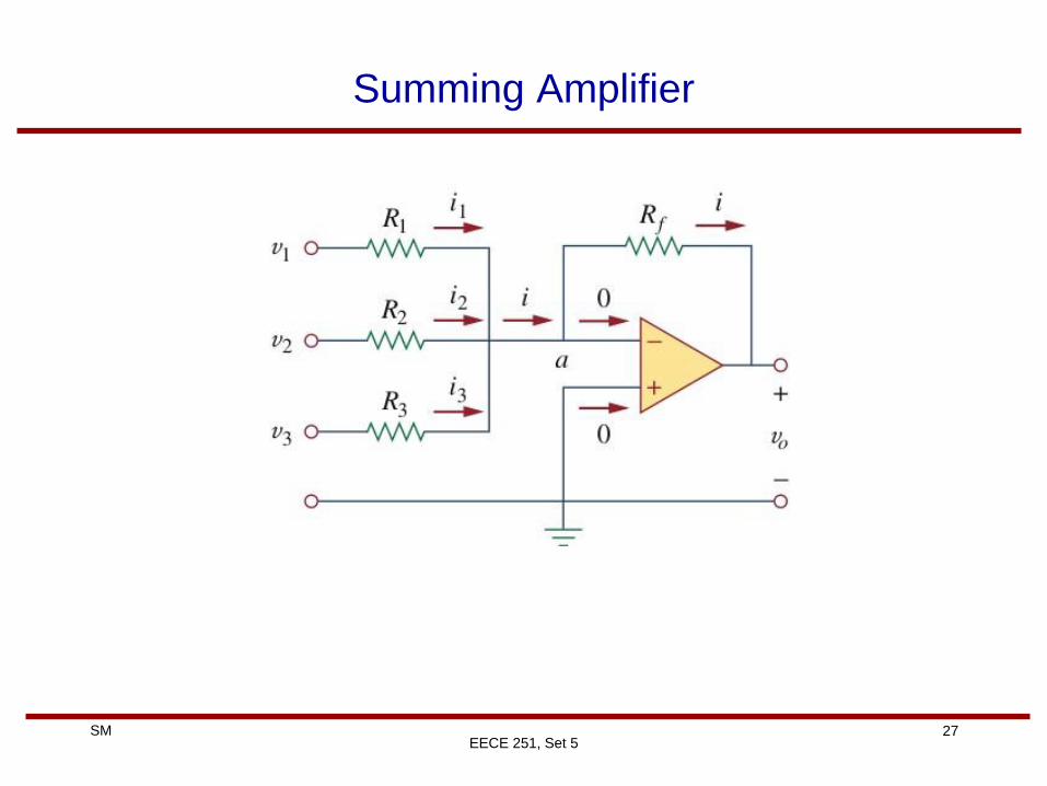
Summing Amplifier
EECE 251, Set 5
Page 28
28 SM
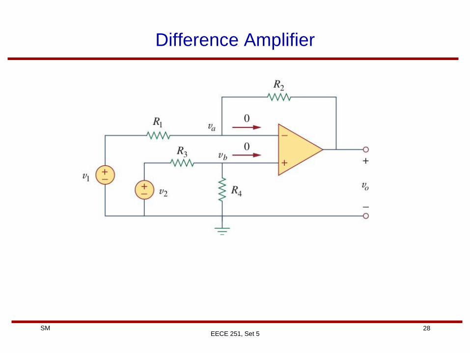
Difference Amplifier
EECE 251, Set 5
Page 29
29 SM
Example
• Design an op amp circuit with inputs v1 and v2 such that
vo= – 2v1+1.5v2
EECE 251, Set 5
Page 30
30 SM
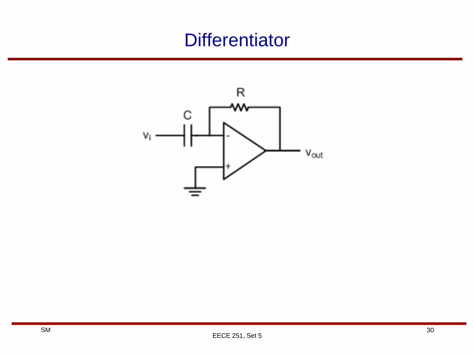
Differentiator
EECE 251, Set 5
Page 31
31 SM
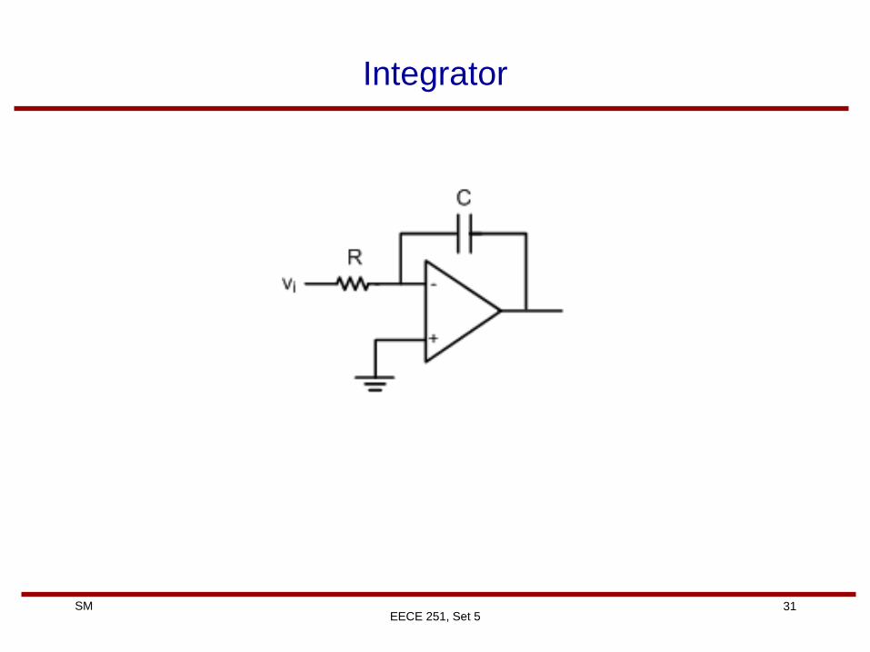
Integrator
EECE 251, Set 5
Page 32
32 SM
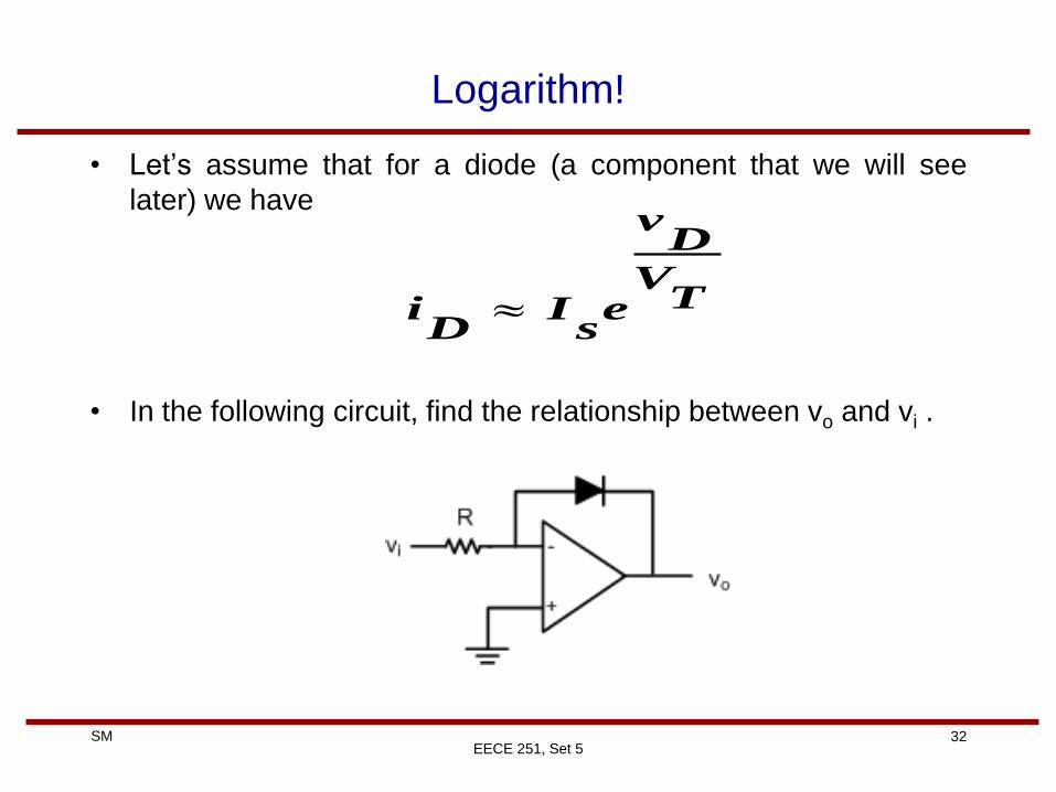
Logarithm!
• Let’s assume that for a diode (a component that we will see
later) we have
• In the following circuit, find the relationship between vo and vi .
EECE 251, Set 5
TV
Dv
es
ID
i
Page 33
33 SM
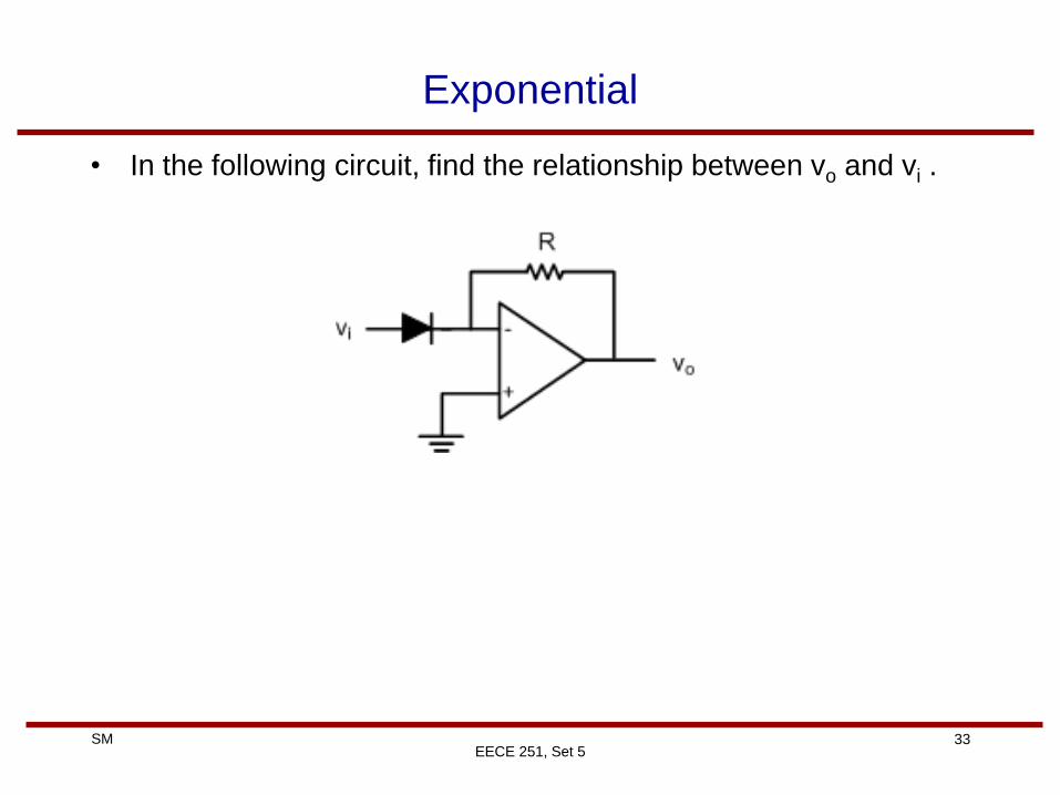
Exponential
• In the following circuit, find the relationship between vo and vi .
EECE 251, Set 5
Page 34
34 SM
Multiplication and Division
• Can you think of a circuit that can be used to multiply two
voltages?
• How about a circuit that can be used to divide two voltages?
EECE 251, Set 5
Page 35
35 SM
Example
EECE 251, Set 5
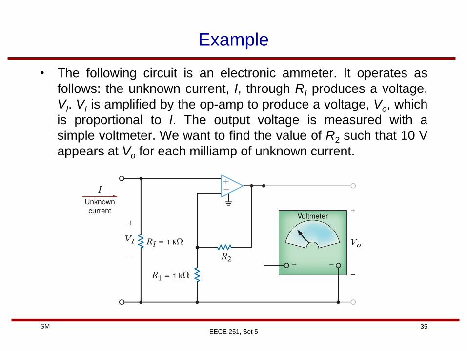
• The following circuit is an electronic ammeter. It operates as
follows: the unknown current, I, through RI produces a voltage,
VI. VI is amplified by the op-amp to produce a voltage, Vo, which
is proportional to I. The output voltage is measured with a
simple voltmeter. We want to find the value of R2 such that 10 V
appears at Vo for each milliamp of unknown current.
Page 36
36 SM
Example
EECE 251, Set 5
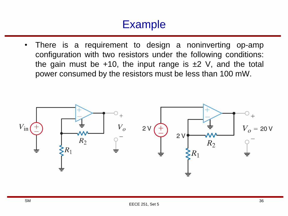
• There is a requirement to design a noninverting op-amp
configuration with two resistors under the following conditions:
the gain must be +10, the input range is ±2 V, and the total
power consumed by the resistors must be less than 100 mW.
Page 37
37 SM
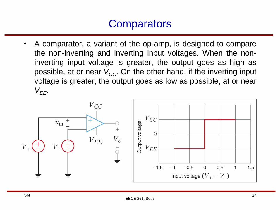
Comparators
EECE 251, Set 5
• A comparator, a variant of the op-amp, is designed to compare
the non-inverting and inverting input voltages. When the non-
inverting input voltage is greater, the output goes as high as
possible, at or near VCC. On the other hand, if the inverting input
voltage is greater, the output goes as low as possible, at or near
VEE.
Page 38
38 SM
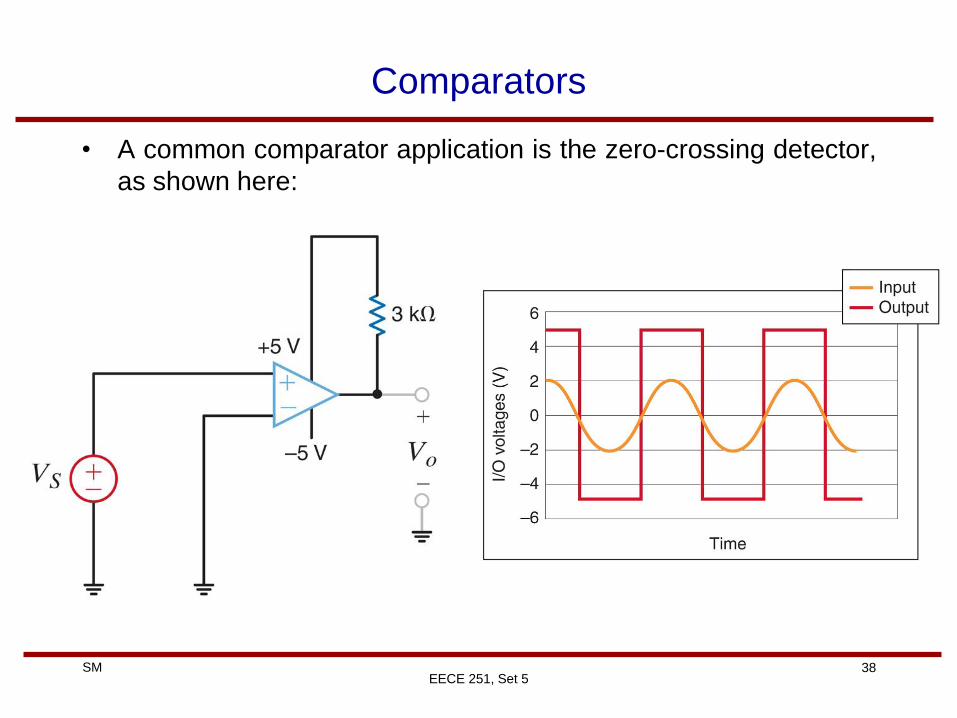
Comparators
• A common comparator application is the zero-crossing detector,
as shown here:
EECE 251, Set 5
Page 39
39 SM
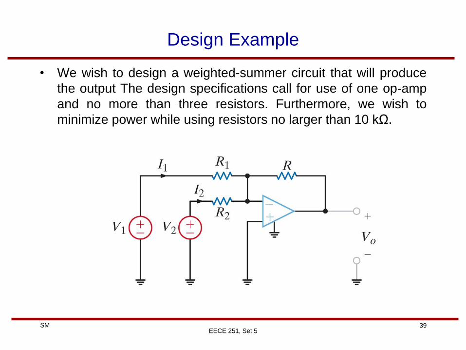
Design Example
• We wish to design a weighted-summer circuit that will produce
the output The design specifications call for use of one op-amp
and no more than three resistors. Furthermore, we wish to
minimize power while using resistors no larger than 10 kΩ.
EECE 251, Set 5
Page 40
40 SM
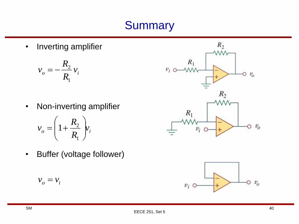
Summary
• Inverting amplifier
• Non-inverting amplifier
• Buffer (voltage follower)
EECE 251, Set 5
io vR
Rv
1
2
io vR
Rv
1
21
io vv
Page 41
41 SM
Summary
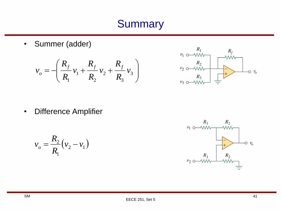
• Summer (adder)
• Difference Amplifier
EECE 251, Set 5
3
3
2
2
1
1
vR
Rv
R
Rv
R
Rv
fff
o
12
1
2 vvR
Rvo
Page 42
42 SM
Summary
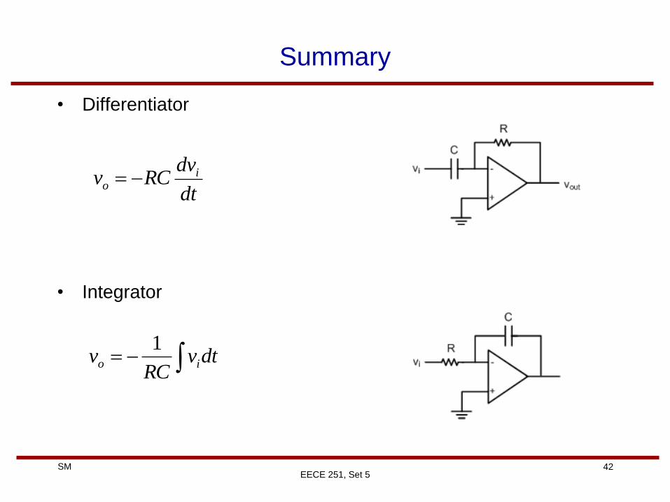
• Differentiator
• Integrator
EECE 251, Set 5
dt
dvRCv i
o
dtvRC
v io
1
Page 43
43 SM
Summary
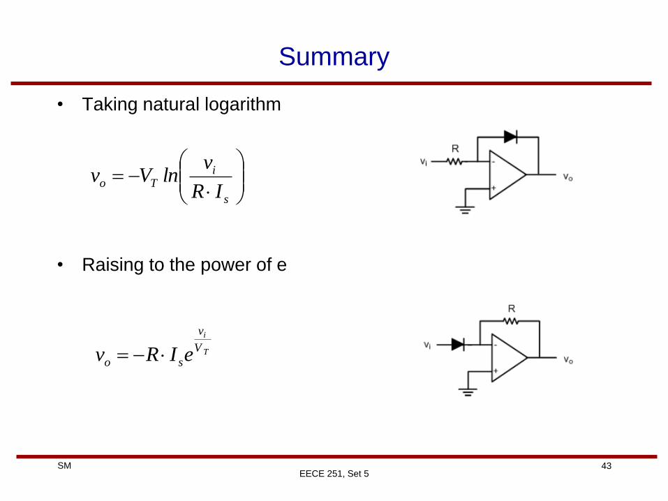
• Taking natural logarithm
• Raising to the power of e
EECE 251, Set 5
s
iTo
IR
vlnVv
T
i
V
v
so eIRv
Page 44
44 SM
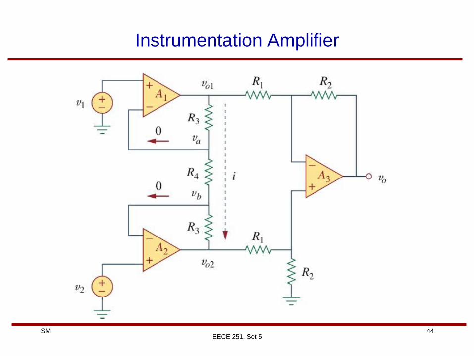
Instrumentation Amplifier
EECE 251, Set 5