16
EEE130 Digital Electronics I Lecture #1 By Dr. Shahrel A. Suandi Email: [email protected] or ext. 5814
EEE130 Digital Electronics I
Lecture #1
By
Dr. Shahrel A. Suandi
Email: [email protected] or ext. 5814

About this lecture (1)
• My part:
– Chapter 1 until Chapter 6 (including subtractor)
• Grading scheme:
– 30:70
– 10% assignment, 20% test and 70% exam
• Consultation hour:
– Wednesday 14:00 to 16:00 hours
• URL:
– http://ee.eng.usm.my/eeacad/shahrel/index.html

About this lecture (2)
• Text book:
– “Digital Fundamentals”, Thomas L. Floyd, 9th
Edition, Pearson Education International,
Prentice Hall.
• Other references:
– Check our homepage for this

Lecture schedule
• Our lecture schedule can be found at
EEE130 website.
• Changes, teaching materials, questions,
solutions, announcements and etc. will be
made/given in the given URL, so please
CHECK!!!!

Chapter 1 – Digital Concepts
• What we will learn in this chapter?
– Digital and analog quantities
– Binary digits, logic levels, digital waveforms
– Basic logic operation
– Overview of basic logic functions
– Fixed-function integrated circuits
– Introduction to programmable logic
– Test and measurement instruments
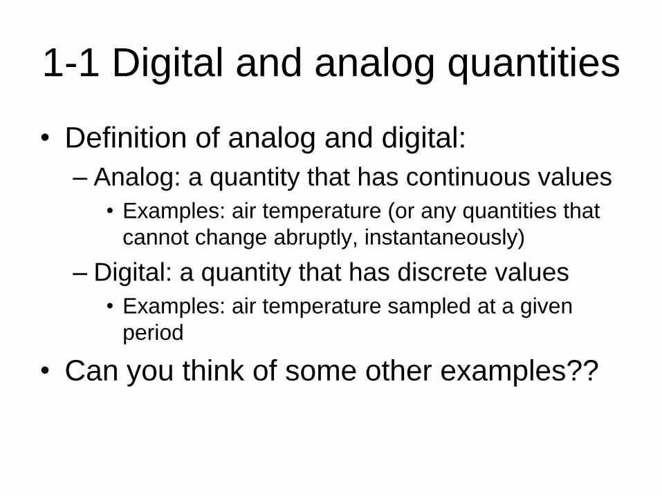
1-1 Digital and analog quantities
• Definition of analog and digital:
– Analog: a quantity that has continuous values
• Examples: air temperature (or any quantities that
cannot change abruptly, instantaneously)
– Digital: a quantity that has discrete values
• Examples: air temperature sampled at a given
period
• Can you think of some other examples??

The advantage of digital
• Digital data can be processed and
transmitted more efficiently and reliably
than analog data
• Digital data requires less space
• Digital data reduces noise

How to get digital signals?
• Through „digitizing‟ process
– Analog signals as input
– Sampling (at certain frequency rates)
– Quantization
– Digital signals
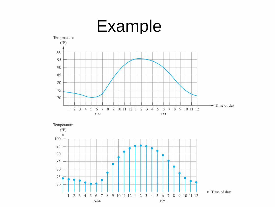
Example

An analog electronic system
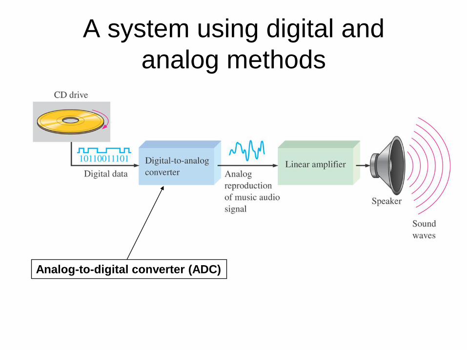
A system using digital and
analog methods
Analog-to-digital converter (ADC)
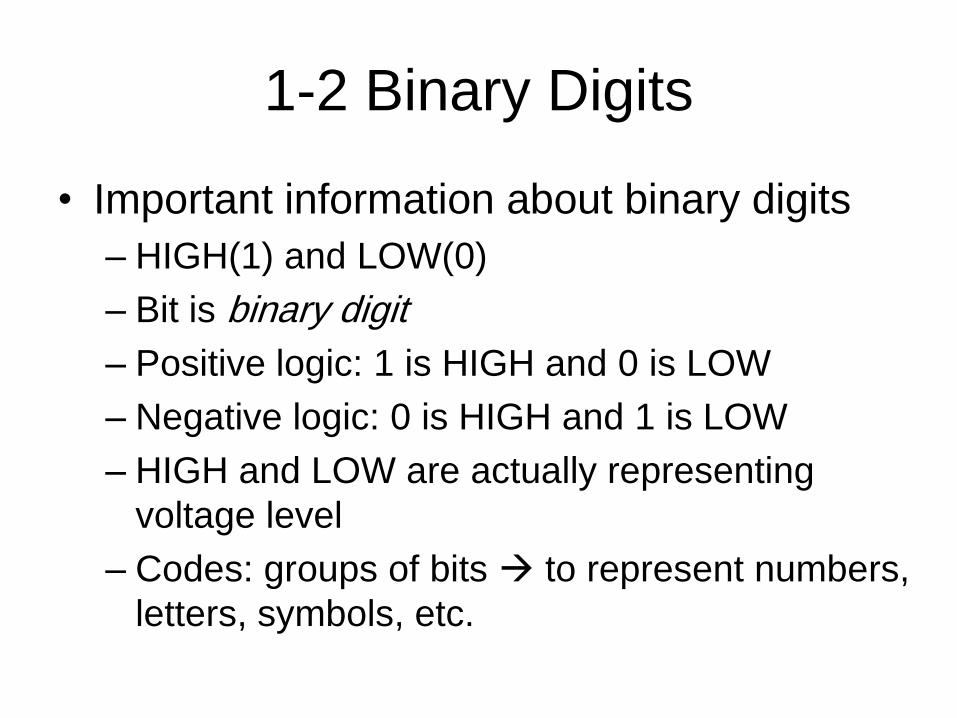
1-2 Binary Digits
• Important information about binary digits
– HIGH(1) and LOW(0)
– Bit is binary digit
– Positive logic: 1 is HIGH and 0 is LOW
– Negative logic: 0 is HIGH and 1 is LOW
– HIGH and LOW are actually representing
voltage level
– Codes: groups of bits to represent numbers,
letters, symbols, etc.

1-2 Logic Levels
• The meaning of logic levels:– The voltages to represent a
1 and 0
• HIGH:– within a specified minimum
and maximum high voltage value
• LOW: – within a specified minimum
and maximum low voltage value
• Examples: – CMOS type IC – HIGH:
(2,3.3)V, LOW: (0,0.8)V

1-2 Digital Waveforms
• Consists of voltage level that are changing
back and forth between HIGH and LOW
levels or states
• There are positive-going, and negative
going pulses
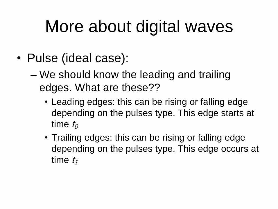
More about digital waves
• Pulse (ideal case):
– We should know the leading and trailing
edges. What are these??
• Leading edges: this can be rising or falling edge
depending on the pulses type. This edge starts at
time t0
• Trailing edges: this can be rising or falling edge
depending on the pulses type. This edge occurs at
time t1

More about digital waves
• Pulse (non ideal case):


